EP3750510B1 - Medizinisches implantat zum gasaustausch - Google Patents
Medizinisches implantat zum gasaustausch Download PDFInfo
- Publication number
- EP3750510B1 EP3750510B1 EP20176847.0A EP20176847A EP3750510B1 EP 3750510 B1 EP3750510 B1 EP 3750510B1 EP 20176847 A EP20176847 A EP 20176847A EP 3750510 B1 EP3750510 B1 EP 3750510B1
- Authority
- EP
- European Patent Office
- Prior art keywords
- hollow body
- fluid
- oxygen
- medical implant
- carbon dioxide
- Prior art date
- Legal status (The legal status is an assumption and is not a legal conclusion. Google has not performed a legal analysis and makes no representation as to the accuracy of the status listed.)
- Active
Links
Images


Classifications
-
- A—HUMAN NECESSITIES
- A61—MEDICAL OR VETERINARY SCIENCE; HYGIENE
- A61F—FILTERS IMPLANTABLE INTO BLOOD VESSELS; PROSTHESES; DEVICES PROVIDING PATENCY TO, OR PREVENTING COLLAPSING OF, TUBULAR STRUCTURES OF THE BODY, e.g. STENTS; ORTHOPAEDIC, NURSING OR CONTRACEPTIVE DEVICES; FOMENTATION; TREATMENT OR PROTECTION OF EYES OR EARS; BANDAGES, DRESSINGS OR ABSORBENT PADS; FIRST-AID KITS
- A61F2/00—Filters implantable into blood vessels; Prostheses, i.e. artificial substitutes or replacements for parts of the body; Appliances for connecting them with the body; Devices providing patency to, or preventing collapsing of, tubular structures of the body, e.g. stents
- A61F2/02—Prostheses implantable into the body
- A61F2/30—Joints
- A61F2/46—Special tools for implanting artificial joints
- A61F2/4675—Special tools for implanting artificial joints for cleaning or coating bones, e.g. bone cavities, prior to endoprosthesis implantation or bone cement introduction
-
- A—HUMAN NECESSITIES
- A61—MEDICAL OR VETERINARY SCIENCE; HYGIENE
- A61B—DIAGNOSIS; SURGERY; IDENTIFICATION
- A61B17/00—Surgical instruments, devices or methods
- A61B17/56—Surgical instruments or methods for treatment of bones or joints; Devices specially adapted therefor
- A61B17/58—Surgical instruments or methods for treatment of bones or joints; Devices specially adapted therefor for osteosynthesis, e.g. bone plates, screws or setting implements
- A61B17/68—Internal fixation devices, including fasteners and spinal fixators, even if a part thereof projects from the skin
- A61B17/70—Spinal positioners or stabilisers, e.g. stabilisers comprising fluid filler in an implant
- A61B17/7097—Stabilisers comprising fluid filler in an implant, e.g. balloon; devices for inserting or filling such implants
- A61B17/7098—Stabilisers comprising fluid filler in an implant, e.g. balloon; devices for inserting or filling such implants wherein the implant is permeable or has openings, e.g. fenestrated screw
-
- A—HUMAN NECESSITIES
- A61—MEDICAL OR VETERINARY SCIENCE; HYGIENE
- A61F—FILTERS IMPLANTABLE INTO BLOOD VESSELS; PROSTHESES; DEVICES PROVIDING PATENCY TO, OR PREVENTING COLLAPSING OF, TUBULAR STRUCTURES OF THE BODY, e.g. STENTS; ORTHOPAEDIC, NURSING OR CONTRACEPTIVE DEVICES; FOMENTATION; TREATMENT OR PROTECTION OF EYES OR EARS; BANDAGES, DRESSINGS OR ABSORBENT PADS; FIRST-AID KITS
- A61F2/00—Filters implantable into blood vessels; Prostheses, i.e. artificial substitutes or replacements for parts of the body; Appliances for connecting them with the body; Devices providing patency to, or preventing collapsing of, tubular structures of the body, e.g. stents
- A61F2/02—Prostheses implantable into the body
- A61F2/28—Bones
-
- A—HUMAN NECESSITIES
- A61—MEDICAL OR VETERINARY SCIENCE; HYGIENE
- A61F—FILTERS IMPLANTABLE INTO BLOOD VESSELS; PROSTHESES; DEVICES PROVIDING PATENCY TO, OR PREVENTING COLLAPSING OF, TUBULAR STRUCTURES OF THE BODY, e.g. STENTS; ORTHOPAEDIC, NURSING OR CONTRACEPTIVE DEVICES; FOMENTATION; TREATMENT OR PROTECTION OF EYES OR EARS; BANDAGES, DRESSINGS OR ABSORBENT PADS; FIRST-AID KITS
- A61F2/00—Filters implantable into blood vessels; Prostheses, i.e. artificial substitutes or replacements for parts of the body; Appliances for connecting them with the body; Devices providing patency to, or preventing collapsing of, tubular structures of the body, e.g. stents
- A61F2/0077—Special surfaces of prostheses, e.g. for improving ingrowth
-
- A—HUMAN NECESSITIES
- A61—MEDICAL OR VETERINARY SCIENCE; HYGIENE
- A61F—FILTERS IMPLANTABLE INTO BLOOD VESSELS; PROSTHESES; DEVICES PROVIDING PATENCY TO, OR PREVENTING COLLAPSING OF, TUBULAR STRUCTURES OF THE BODY, e.g. STENTS; ORTHOPAEDIC, NURSING OR CONTRACEPTIVE DEVICES; FOMENTATION; TREATMENT OR PROTECTION OF EYES OR EARS; BANDAGES, DRESSINGS OR ABSORBENT PADS; FIRST-AID KITS
- A61F2/00—Filters implantable into blood vessels; Prostheses, i.e. artificial substitutes or replacements for parts of the body; Appliances for connecting them with the body; Devices providing patency to, or preventing collapsing of, tubular structures of the body, e.g. stents
- A61F2/02—Prostheses implantable into the body
- A61F2/04—Hollow or tubular parts of organs, e.g. bladders, tracheae, bronchi or bile ducts
- A61F2/06—Blood vessels
-
- A—HUMAN NECESSITIES
- A61—MEDICAL OR VETERINARY SCIENCE; HYGIENE
- A61F—FILTERS IMPLANTABLE INTO BLOOD VESSELS; PROSTHESES; DEVICES PROVIDING PATENCY TO, OR PREVENTING COLLAPSING OF, TUBULAR STRUCTURES OF THE BODY, e.g. STENTS; ORTHOPAEDIC, NURSING OR CONTRACEPTIVE DEVICES; FOMENTATION; TREATMENT OR PROTECTION OF EYES OR EARS; BANDAGES, DRESSINGS OR ABSORBENT PADS; FIRST-AID KITS
- A61F2/00—Filters implantable into blood vessels; Prostheses, i.e. artificial substitutes or replacements for parts of the body; Appliances for connecting them with the body; Devices providing patency to, or preventing collapsing of, tubular structures of the body, e.g. stents
- A61F2/02—Prostheses implantable into the body
- A61F2/30—Joints
- A61F2/30767—Special external or bone-contacting surface, e.g. coating for improving bone ingrowth
-
- A—HUMAN NECESSITIES
- A61—MEDICAL OR VETERINARY SCIENCE; HYGIENE
- A61F—FILTERS IMPLANTABLE INTO BLOOD VESSELS; PROSTHESES; DEVICES PROVIDING PATENCY TO, OR PREVENTING COLLAPSING OF, TUBULAR STRUCTURES OF THE BODY, e.g. STENTS; ORTHOPAEDIC, NURSING OR CONTRACEPTIVE DEVICES; FOMENTATION; TREATMENT OR PROTECTION OF EYES OR EARS; BANDAGES, DRESSINGS OR ABSORBENT PADS; FIRST-AID KITS
- A61F2/00—Filters implantable into blood vessels; Prostheses, i.e. artificial substitutes or replacements for parts of the body; Appliances for connecting them with the body; Devices providing patency to, or preventing collapsing of, tubular structures of the body, e.g. stents
- A61F2/0077—Special surfaces of prostheses, e.g. for improving ingrowth
- A61F2002/0086—Special surfaces of prostheses, e.g. for improving ingrowth for preferentially controlling or promoting the growth of specific types of cells or tissues
-
- A—HUMAN NECESSITIES
- A61—MEDICAL OR VETERINARY SCIENCE; HYGIENE
- A61F—FILTERS IMPLANTABLE INTO BLOOD VESSELS; PROSTHESES; DEVICES PROVIDING PATENCY TO, OR PREVENTING COLLAPSING OF, TUBULAR STRUCTURES OF THE BODY, e.g. STENTS; ORTHOPAEDIC, NURSING OR CONTRACEPTIVE DEVICES; FOMENTATION; TREATMENT OR PROTECTION OF EYES OR EARS; BANDAGES, DRESSINGS OR ABSORBENT PADS; FIRST-AID KITS
- A61F2/00—Filters implantable into blood vessels; Prostheses, i.e. artificial substitutes or replacements for parts of the body; Appliances for connecting them with the body; Devices providing patency to, or preventing collapsing of, tubular structures of the body, e.g. stents
- A61F2/02—Prostheses implantable into the body
- A61F2/28—Bones
- A61F2002/2825—Femur
-
- A—HUMAN NECESSITIES
- A61—MEDICAL OR VETERINARY SCIENCE; HYGIENE
- A61F—FILTERS IMPLANTABLE INTO BLOOD VESSELS; PROSTHESES; DEVICES PROVIDING PATENCY TO, OR PREVENTING COLLAPSING OF, TUBULAR STRUCTURES OF THE BODY, e.g. STENTS; ORTHOPAEDIC, NURSING OR CONTRACEPTIVE DEVICES; FOMENTATION; TREATMENT OR PROTECTION OF EYES OR EARS; BANDAGES, DRESSINGS OR ABSORBENT PADS; FIRST-AID KITS
- A61F2/00—Filters implantable into blood vessels; Prostheses, i.e. artificial substitutes or replacements for parts of the body; Appliances for connecting them with the body; Devices providing patency to, or preventing collapsing of, tubular structures of the body, e.g. stents
- A61F2/02—Prostheses implantable into the body
- A61F2/28—Bones
- A61F2002/2835—Bone graft implants for filling a bony defect or an endoprosthesis cavity, e.g. by synthetic material or biological material
-
- A—HUMAN NECESSITIES
- A61—MEDICAL OR VETERINARY SCIENCE; HYGIENE
- A61F—FILTERS IMPLANTABLE INTO BLOOD VESSELS; PROSTHESES; DEVICES PROVIDING PATENCY TO, OR PREVENTING COLLAPSING OF, TUBULAR STRUCTURES OF THE BODY, e.g. STENTS; ORTHOPAEDIC, NURSING OR CONTRACEPTIVE DEVICES; FOMENTATION; TREATMENT OR PROTECTION OF EYES OR EARS; BANDAGES, DRESSINGS OR ABSORBENT PADS; FIRST-AID KITS
- A61F2/00—Filters implantable into blood vessels; Prostheses, i.e. artificial substitutes or replacements for parts of the body; Appliances for connecting them with the body; Devices providing patency to, or preventing collapsing of, tubular structures of the body, e.g. stents
- A61F2/02—Prostheses implantable into the body
- A61F2/30—Joints
- A61F2002/30001—Additional features of subject-matter classified in A61F2/28, A61F2/30 and subgroups thereof
- A61F2002/30003—Material related properties of the prosthesis or of a coating on the prosthesis
- A61F2002/3006—Properties of materials and coating materials
- A61F2002/30062—(bio)absorbable, biodegradable, bioerodable, (bio)resorbable, resorptive
-
- A—HUMAN NECESSITIES
- A61—MEDICAL OR VETERINARY SCIENCE; HYGIENE
- A61F—FILTERS IMPLANTABLE INTO BLOOD VESSELS; PROSTHESES; DEVICES PROVIDING PATENCY TO, OR PREVENTING COLLAPSING OF, TUBULAR STRUCTURES OF THE BODY, e.g. STENTS; ORTHOPAEDIC, NURSING OR CONTRACEPTIVE DEVICES; FOMENTATION; TREATMENT OR PROTECTION OF EYES OR EARS; BANDAGES, DRESSINGS OR ABSORBENT PADS; FIRST-AID KITS
- A61F2/00—Filters implantable into blood vessels; Prostheses, i.e. artificial substitutes or replacements for parts of the body; Appliances for connecting them with the body; Devices providing patency to, or preventing collapsing of, tubular structures of the body, e.g. stents
- A61F2/02—Prostheses implantable into the body
- A61F2/30—Joints
- A61F2002/30001—Additional features of subject-matter classified in A61F2/28, A61F2/30 and subgroups thereof
- A61F2002/30667—Features concerning an interaction with the environment or a particular use of the prosthesis
- A61F2002/30677—Means for introducing or releasing pharmaceutical products, e.g. antibiotics, into the body
-
- A—HUMAN NECESSITIES
- A61—MEDICAL OR VETERINARY SCIENCE; HYGIENE
- A61F—FILTERS IMPLANTABLE INTO BLOOD VESSELS; PROSTHESES; DEVICES PROVIDING PATENCY TO, OR PREVENTING COLLAPSING OF, TUBULAR STRUCTURES OF THE BODY, e.g. STENTS; ORTHOPAEDIC, NURSING OR CONTRACEPTIVE DEVICES; FOMENTATION; TREATMENT OR PROTECTION OF EYES OR EARS; BANDAGES, DRESSINGS OR ABSORBENT PADS; FIRST-AID KITS
- A61F2250/00—Special features of prostheses classified in groups A61F2/00 - A61F2/26 or A61F2/82 or A61F9/00 or A61F11/00 or subgroups thereof
-
- A—HUMAN NECESSITIES
- A61—MEDICAL OR VETERINARY SCIENCE; HYGIENE
- A61F—FILTERS IMPLANTABLE INTO BLOOD VESSELS; PROSTHESES; DEVICES PROVIDING PATENCY TO, OR PREVENTING COLLAPSING OF, TUBULAR STRUCTURES OF THE BODY, e.g. STENTS; ORTHOPAEDIC, NURSING OR CONTRACEPTIVE DEVICES; FOMENTATION; TREATMENT OR PROTECTION OF EYES OR EARS; BANDAGES, DRESSINGS OR ABSORBENT PADS; FIRST-AID KITS
- A61F2310/00—Prostheses classified in A61F2/28 or A61F2/30 - A61F2/44 being constructed from or coated with a particular material
- A61F2310/00005—The prosthesis being constructed from a particular material
- A61F2310/00179—Ceramics or ceramic-like structures
- A61F2310/00293—Ceramics or ceramic-like structures containing a phosphorus-containing compound, e.g. apatite
-
- A—HUMAN NECESSITIES
- A61—MEDICAL OR VETERINARY SCIENCE; HYGIENE
- A61F—FILTERS IMPLANTABLE INTO BLOOD VESSELS; PROSTHESES; DEVICES PROVIDING PATENCY TO, OR PREVENTING COLLAPSING OF, TUBULAR STRUCTURES OF THE BODY, e.g. STENTS; ORTHOPAEDIC, NURSING OR CONTRACEPTIVE DEVICES; FOMENTATION; TREATMENT OR PROTECTION OF EYES OR EARS; BANDAGES, DRESSINGS OR ABSORBENT PADS; FIRST-AID KITS
- A61F2310/00—Prostheses classified in A61F2/28 or A61F2/30 - A61F2/44 being constructed from or coated with a particular material
- A61F2310/00005—The prosthesis being constructed from a particular material
- A61F2310/00359—Bone or bony tissue
-
- A—HUMAN NECESSITIES
- A61—MEDICAL OR VETERINARY SCIENCE; HYGIENE
- A61F—FILTERS IMPLANTABLE INTO BLOOD VESSELS; PROSTHESES; DEVICES PROVIDING PATENCY TO, OR PREVENTING COLLAPSING OF, TUBULAR STRUCTURES OF THE BODY, e.g. STENTS; ORTHOPAEDIC, NURSING OR CONTRACEPTIVE DEVICES; FOMENTATION; TREATMENT OR PROTECTION OF EYES OR EARS; BANDAGES, DRESSINGS OR ABSORBENT PADS; FIRST-AID KITS
- A61F2310/00—Prostheses classified in A61F2/28 or A61F2/30 - A61F2/44 being constructed from or coated with a particular material
- A61F2310/00005—The prosthesis being constructed from a particular material
- A61F2310/00365—Proteins; Polypeptides; Degradation products thereof
- A61F2310/00371—Collagen
-
- A—HUMAN NECESSITIES
- A61—MEDICAL OR VETERINARY SCIENCE; HYGIENE
- A61F—FILTERS IMPLANTABLE INTO BLOOD VESSELS; PROSTHESES; DEVICES PROVIDING PATENCY TO, OR PREVENTING COLLAPSING OF, TUBULAR STRUCTURES OF THE BODY, e.g. STENTS; ORTHOPAEDIC, NURSING OR CONTRACEPTIVE DEVICES; FOMENTATION; TREATMENT OR PROTECTION OF EYES OR EARS; BANDAGES, DRESSINGS OR ABSORBENT PADS; FIRST-AID KITS
- A61F2310/00—Prostheses classified in A61F2/28 or A61F2/30 - A61F2/44 being constructed from or coated with a particular material
- A61F2310/00005—The prosthesis being constructed from a particular material
- A61F2310/00365—Proteins; Polypeptides; Degradation products thereof
- A61F2310/00383—Gelatin
-
- A—HUMAN NECESSITIES
- A61—MEDICAL OR VETERINARY SCIENCE; HYGIENE
- A61M—DEVICES FOR INTRODUCING MEDIA INTO, OR ONTO, THE BODY; DEVICES FOR TRANSDUCING BODY MEDIA OR FOR TAKING MEDIA FROM THE BODY; DEVICES FOR PRODUCING OR ENDING SLEEP OR STUPOR
- A61M27/00—Drainage appliance for wounds or the like, i.e. wound drains, implanted drains
Definitions
- the invention relates to a medical implant for the treatment of bone defects and a bone defect treatment system having such an implant.
- the invention also relates to a method for gassing a surface of a medical implant.
- the subject of the invention is therefore a medical implant for temporary implantation in bone cavities.
- Bone defects can have a variety of causes in humans. Common causes include trauma and infection. Bone defects do not heal spontaneously if they exceed a critical size. There is then a so-called “critical size defect”. To treat bone defects, bone replacement materials of various structures and compositions, as well as allogeneic bone tissue and autologous bone tissue, are used clinically.
- Bone replacement materials have been known for decades and can be made from a wide variety of materials. Typical inorganic bone replacement materials are calcium sulfate ( H. Dreesmann: About bone sealing. Clinical Surgery (1892) 804-810 ), carbonatapatite ( MV Vallet-Regi, JM Gonzalez-Cabbet: Calcium phosphates as substitution of bone tissues. Progress in Solid State Chemistry 32 (1-2) (2004)1-31 ), hydroxyapatite, ⁇ -tricalcium phosphate ( RW Bucholz, A. Carlton, RE Holmes: Hydroxyapatite and tricalcium phosphate bone graft substitutes. The Orthopedic Clinics of North America 18(2) (1987) 323-334 ), organic glasses ( H.
- the US 2001/0004710 A1 discloses a spacer for treating a cavity of a patient in which a balloon can be inflated and a curable biomaterial can be fed into the balloon. Gas exchange is not planned.
- Gas Permeability of Thermoplastic Polyurethane Elastomers by Katuji Matsunaga et al. in Polymer Jounal Vol. 37, No. 6, pages 413-417 (2205) is a known plastic that is permeable to oxygen and CO 2 .
- bone replacement materials are successfully used for relatively small bone defects.
- the bone tissue In the case of larger bone defects in the extremity area, it is often clinically observed that even when porous bone replacement materials are used, the bone tissue only grows superficially into the bone replacement material. Similar problems occur with the transplantation of autologous bone tissue and also with combinations of autologous bone material and inorganic bone replacement materials.
- the autologous tissue which is located furthest away from the well-supplied bone tissue, is often damaged and often dies.
- the object on which the present invention is based can therefore be seen as finding a way and, if necessary, providing a medical implant with which the chances of recovery are improved. Stabilization and ossification of the bone defect should be achieved as quickly and as easily as possible. Other aids can also be used that have a positive effect on the healing process.
- the object of the invention is therefore to develop a temporary medical implant that is intended to enable gas exchange with its environment.
- the implant should be able to release oxygen into the environment on its surface and to absorb and transport carbon dioxide from the environment. The release of oxygen and the uptake should be possible continuously or discontinuously.
- the gas exchange and gas transport should be achieved by a fluid which should flow through the medical implant.
- the medical implant should be explantable and should not be able to grow with human or animal tissue.
- the temporary medical implant is intended to enable gas exchange with surrounding bone replacement materials and in particular with autologous bone tissue and also bone replacement materials populated with cells, such as osteoblasts.
- a further object of the invention is the development of a bone replacement material system which contains the temporary medical implant to be developed as a component.
- An additional object of the present invention is also to develop a non-medical method with which oxygen can be delivered into a cavity and carbon dioxide can be absorbed from the cavity at the same time.
- the method should be feasible with the medical implant according to the invention and should be used in cavities that are not part of a human or animal body.
- the medical implant is also intended for gas exchange with the surrounding tissue, with oxygen or a flushing gas mixture containing oxygen or an oxygen-enriched flushing liquid flowing as a fluid continuously or discontinuously through the interior of the spacer and supplying oxygen to the tissue via the permeable outer wall of the implant and carbon dioxide can be removed at the same time.
- a medical implant for the treatment of bone defects having at least one hollow body which delimits an interior space inside the hollow body, a fluid supply line which is connected in a fluid-permeable manner to the interior space of the hollow body, and a fluid discharge line which is connected to the interior space of the hollow body is connected in a fluid-permeable manner
- the hollow body consists at least partially or completely of at least one plastic, wherein the at least one plastic is impermeable to liquids and is permeable to oxygen and carbon dioxide, so that oxygen from a fluid passed through the hollow body to the environment of the hollow body can be released and carbon dioxide can be absorbed into the fluid from the environment of the hollow body
- the hollow body or the at least one plastic of the hollow body has a permeability coefficient for oxygen of greater than or equal to 0.5 cm 3 / (m 2 *d*bar) and a permeability coefficient for carbon dioxide of greater than or equal to 0.5 cm 3 /(m 2 *d*bar).
- the medical implant is preferably a temporary medical implant.
- the fluid passed through the hollow body must be suitable for releasing oxygen and absorbing carbon dioxide.
- the medical implant is suitable for temporary implantation in bone cavities.
- the hollow body is made of a plastic that is permeable to oxygen and carbon dioxide.
- the interior is closed off from the surroundings of the medical implant.
- the at least one plastic preferably forms, at least in some areas, a continuous wall of the hollow body. This means that there are areas of the wall of the hollow body in which there is no other additional material apart from the at least one plastic. Well-permeable nets and wires, especially those made of metal, do not cause any problems. This is intended to ensure that the permeability of the plastic to oxygen and carbon dioxide can be used to ensure that the wall of the hollow body is also permeable to oxygen and carbon dioxide, at least in these areas.
- a wall delimiting the interior of the hollow body is permeable to oxygen and carbon dioxide.
- the hollow body is tubular, wherein the fluid supply line and the fluid discharge line are preferably connected to the hollow body on one end face of the hollow body or are connected to the interior of the hollow body on two opposite end faces of the hollow body .
- Tubular hollow bodies are particularly suitable as spacers, particularly in the case of bone defects in long bones.
- the hollow body can also have any other shape, depending on the size and shape of the bone defect to be temporarily filled.
- the fluid can be gaseous or liquid. Mixtures of liquids and gases are also possible. Air, oxygen, saline solution saturated with oxygen, Ringer's solution saturated with oxygen, Ringer's lactate solution saturated with oxygen, phosphate buffer solution saturated with oxygen and perfluorodecalin saturated with oxygen and mixtures thereof are preferred as fluids. It is essential that the fluid contains oxygen and that the fluid can absorb carbon dioxide. All fluids that can transport oxygen and carbon dioxide and can exchange these substances with the environment via the permeable wall of the hollow body are therefore suitable.
- the hollow body or the at least one plastic of the hollow body has a permeability coefficient for oxygen of greater than or equal to 0.5 cm 3 / (m 2 *d*bar) and a permeability coefficient for carbon dioxide of greater than or equal to 0.5 cm 3 /(m 2 *d*bar), preferably a permeability coefficient for oxygen of greater than or equal to 1 cm 3 /(m 2 *d*bar) and a permeability coefficient for carbon dioxide of greater than or equal to 1 cm 3 /(m 2 * d*bar).
- the permeability coefficient is determined according to DIN 53380-4 (11/2006). This applies in particular to the testing of plastics, here the determination of gas permeability, whereby part 4 of DIN 53380 standardizes a carbon dioxide-specific infrared absorption method for measuring plastic films and plastic molded parts, which can also be transferred to oxygen. Such measurements are carried out and offered, for example, by the company Mecadi GmbH (Bexbach, Germany).
- the hollow body or the at least one plastic of the hollow body has a permeability coefficient for oxygen of greater than or equal to 0.5 cm 3 / (m 2 *d*bar) and a permeability coefficient for carbon dioxide of equal to/greater than 0, 5 cm 3 / (m 2 *d*bar) according to DIN 53380-4 (11/2006), preferably a permeability coefficient for oxygen of greater than or equal to 1 cm 3 / (m 2 *d*bar) and a permeability coefficient for carbon dioxide of greater than or equal to 1 cm 3 /(m 2 *d*bar) according to DIN 53380-4 (11/2006).
- Permeability generally refers to the property of solids to allow gases and/or liquids to pass through. In the present case, this refers to the permeability of the walls of the hollow body and this relates to molecular oxygen and molecular carbon dioxide in gaseous form.
- the permeability coefficient is a material-specific constant and is a measure of the permeability for liquids and gases.
- the unit d stands for a day (day).
- the fluid supply line and the fluid discharge line open into the hollow body in such a way that when the fluid flows through the fluid supply line through the hollow body into the fluid discharge line, the fluid flows over an entire inner surface of the hollow body or at least over 50% of the entire inner surface of the hollow body flows.
- the branches are also considered to be part of the surface over which flow occurs, even if the main part of the flow of the fluid moves along the main strand past the branches. What is important here is that the inner surfaces of the branches are accessible from the main flow of the fluid.
- an inflow opening of the fluid supply line with which the fluid supply line opens into the interior, is arranged spatially separated from an outflow opening of the fluid drainage line, the outflow opening forming the opening of the interior space into the fluid drainage line.
- the inflow opening is the opening of the fluid supply line through which the fluid flows from the fluid supply line into the interior of the hollow body.
- the outflow opening is the opening of the fluid drain through which the fluid flows out of the interior of the hollow body into the fluid drain.
- the inflow opening of the fluid supply line is arranged at a first end of the hollow body and the outflow opening is arranged at a second end of the hollow body opposite the first end.
- This increases the residence time of the fluid flowing through on the inner wall of the hollow body or on the inner wall of the at least one plastic and improves the gas exchange through the hollow body or the at least one plastic.
- the fluid supply line and the fluid discharge line are both connected to the hollow body on one side of the hollow body.
- a sterile filter that is impermeable to germs but permeable to gases is arranged in the fluid supply line and/or the fluid discharge line.
- a valve is arranged in the fluid supply line and/or the fluid discharge line, in particular a one-way valve is arranged, the one-way valve preferably being a check valve.
- the pressure inside the hollow body can be adjusted using a suitable adjustable valve, thus achieving a specific shape or a specific rigidity of the medical implant.
- the valve is arranged in the fluid discharge line and is designed as a pressure relief valve, the opening pressure of the pressure relief valve preferably being adjustable.
- the expanded state of the hollow body can be safely achieved and maintained.
- a one-way valve in the fluid drain can ensure that a pressure can be built up inside the hollow body with the fluid and that the fluid used cannot get back into the hollow body. It can therefore be particularly preferably provided that a one-way valve is arranged in the fluid discharge line.
- the fluid supply line and the fluid discharge line consist of a material that is not permeable to oxygen and carbon dioxide, preferably made of a plastic that is not permeable to oxygen and carbon dioxide.
- the fluid supply line and the fluid discharge line can be made from a more cost-effective plastic.
- the hollow body or the at least one plastic of the hollow body contains at least one antiseptic active ingredient or is coated with at least one antiseptic active ingredient.
- the surface of the medical implant and the surroundings of the medical implant in the patient's body can be disinfected with the at least one antiseptic active ingredient. This avoids complications during treatment.
- the hollow body is a hollow cylinder or that the hollow body has a main strand in the form of a hollow cylinder, the fluid supply line and the fluid discharge line opening into the hollow cylinder in the area of opposite base surfaces of the hollow cylinder, the hollow cylinder preferably being a part of the fluid supply line or the Fluid drainage coaxially surrounds.
- the implant Due to its cylindrical shape, the implant can be inserted into bone defects in long bones. In addition, it can be ensured that the fluid flows over as large a surface as possible on the wall of the hollow body, so that the gas exchange is supported.
- the hollow body is designed as a perforated metal body or plastic body, the outside of which is covered with a plastic layer that is permeable to oxygen and carbon dioxide.
- the hollow body has a plastic jacket that is permeable to oxygen and carbon dioxide and can be plastically deformed, the plastic jacket preferably containing spiral-shaped and / or net-like metal wires.
- a line with several openings for dispensing an active ingredient is arranged on the hollow body, the line being connected to an active ingredient supply line, the sum of the free cross-sectional areas of the openings preferably being smaller than the free cross-section of the line and the active ingredient supply.
- Possible pharmaceutical active ingredients include antibiotics, antiseptics, anti-inflammatory drugs, bisphosphonates, growth factors, bacteriophages, lysostaphin and muramidases.
- the line with the openings it is also possible to force antiseptic or antibiotic solutions through the openings to the surroundings of the medical implant.
- the line also enables antimicrobial protection of the surface of the medical implant. It is also possible to introduce liquid or gel-like antibiotic or antiseptic pharmaceutical preparations through the line, which can migrate into the environment by diffusion and can thus be used to treat the patient in the area of the medical implant.
- the at least one plastic is an elastic and/or plastic, non-biodegradable plastic, with the at least one plastic preferably being selected from polyurethane, ethylene-propylene-diene rubber EPDM and silicone, or the at least one plastic is an elastic and/or plastic, biodegradable plastic, with the at least one plastic preferably being selected from gelatin, cross-linked collagen and cross-linked albumin.
- an easily removable medical implant can be provided (non-biodegradable plastic) or the medical implant can be partially or completely broken down in the body (biodegradable plastic) and does not have to be removed again or not completely.
- the hollow body can be expanded and/or contracted relative to the surrounding atmosphere by changing the pressure in its interior.
- the selected shape of the hollow body can be ensured by a suitable internal pressure of the hollow body.
- the insertion and removal of the medical implant can be simplified in this way.
- the hollow body has a main strand and several branches extending laterally therefrom, the interior of the hollow body extending in the main strand and in the branches and the fluid supply line and the fluid discharge line being connected to the main strand, wherein preferably at least the branches or walls of the branches consist of the plastic or are constructed with the plastic.
- the interior space in the branches preferably has a smaller cross section than in the main strand.
- the surface of the hollow body can be enlarged and a larger number of cells can be supplied, in particular supplied extracorporeally.
- the hollow body consists of at least one resorbable and/or biodegradable material.
- the fluid supply line and the fluid discharge line can be easily separated for this purpose.
- growth-promoting substances include tricalcium phosphate or similar substances.
- the cells multiplied in this way can then be implanted together with the medical implant or without the medical implant.
- the hollow body is made from a cross-linked gelatin or biopolymers, the medical implant can be degradable down to the connections. The same is also possible if the hollow body is made of degradable hollow fibers.
- the hollow body or the entire medical implant can be folded as a three-dimensional structure. This allows the medical implant to be designed to be adaptable to the shape of the cavity to be treated.
- the medical implant can be used as a ventilable scaffold for cell cultivation.
- tissue engineering TE
- a "scaffold" is an umbrella term for the artificial production of biological tissue through the directed cultivation of cells in order to replace or regenerate diseased tissue in a patient. No medical treatment of a patient is necessary for this, as this only takes place later with the help of the artificially produced cells.
- the medical implant can then be used as a support structure for cell cultures.
- the objects on which the present invention is based are also achieved by a bone defect treatment system comprising such a medical implant according to the invention and the fluid, the fluid containing oxygen and being suitable for absorbing carbon dioxide.
- This provides a complete system (bone defect treatment system) in which the fluid can already be tailored to the medical implant or both to the treatment situation.
- the fluid is selected from air, oxygen, saline solution saturated with oxygen, Ringer's solution saturated with oxygen, Ringer's lactate solution saturated with oxygen, phosphate buffer solution saturated with oxygen and perfluorodecalin saturated with oxygen or a mixture of at least two of the gases or liquids mentioned.
- the bone defect treatment system has a bone replacement material, wherein the bone replacement material is applied to the outer surface of the hollow body or can be applied to the outer surface of the hollow body.
- a further completed bone defect treatment system is hereby provided which contains all components necessary and helpful for treating a bone defect.
- the bone replacement material is selected from a non-biodegradable, a partially degradable, a completely biodegradable bone replacement material and mixtures thereof.
- the bone replacement material is selected from autologous bone tissue, allogeneic bone tissue, hydroxyapatite, carbonatapatite, ⁇ -tricalcium phosphate, ⁇ -tricalcium phosphate, calcium dihydrate, brushite, monetite and mixtures thereof, or the bone replacement material contains living cells and/or is populated with living cells on its surface.
- These bone replacement materials can be used particularly well with the medical implant according to the invention. Supplying these bone replacement materials with oxygen and deacidification through carbon dioxide absorption have a particularly good effect on the treatment situation with these bone replacement materials.
- the medical implant is combined with autologous bone tissue and particularly preferably with autologous cancellous bone.
- the cells of the autologous bone tissue are supplied with oxygen and at the same time the carbon dioxide released during the metabolism of the cells is removed. Lack of oxygen can hinder the cells from breathing, so that they first begin to ferment and then die. Fermentation processes can cause local acidification. Furthermore, local hyperacidification is prevented by the removal of the carbon dioxide formed.
- Steps B) and C) preferably take place simultaneously.
- the gas exchange in steps B) and C) preferably also takes place during step A) and the entire time during step D).
- Air or oxygen can be used as fluid. It is also within the scope of the invention if, instead of air or oxygen as the fluid, rinsing liquids saturated with oxygen, such as physiological saline solution, Ringer's solution or Ringer's lactate solution, are introduced into the medical implant, in particular through the fluid supply line. It is also possible to use perfluorinated decalin as the oxygen carrier or other perfluorinated liquids in which oxygen is soluble as the fluid. Through the fluid drainage, these fluids can be drained out of the hollow body again.
- the method is not carried out for the medical treatment of a human or animal body.
- the method is carried out outside a human or animal body.
- the method according to the invention is not carried out by a doctor or a medical professional.
- medical implants according to the invention also allow extracorporeal proliferation of cells.
- cells and nutrients can be applied to the outer surface of the plastic or the hollow body. These are then supplied with oxygen via the fluid, while carbon dioxide is removed from the growing cell cultures.
- step A) the hollow body is introduced into a cavity and a bone replacement material is applied to the surface of the medical implant and / or is introduced into the cavity between the medical implant and the inner walls delimiting the cavity.
- the cavity is preferably not a cavity of a human or animal body.
- the method is used for the extracorporeal proliferation of cells, in particular bone cells, with the cells being applied to the outer surface of the hollow body before step A), preferably together with a nutrient solution and/or growth-promoting substances on the outer surface of the hollow body are applied.
- the medical implant can thus be used extracorporeally to ventilate and multiply a cell culture for bone cells on the surface of the hollow body. Provided with the grown cell culture, the medical implant can then be implanted and then ventilated further inside the body in order to promote further proliferation and growth of the cells in the bone defect.
- the medical implant does not have to be removed if the hollow body is biodegradable or can be broken down by the body.
- the connections or the fluid supply line and the fluid discharge line can then simply be cut off at a desired time and the hollow body and the growing cells remain in the body and are reabsorbed.
- the invention is based on the surprising finding that the medical implant makes it possible to support the development of the surrounding bone structure by supplying the surroundings of the medical implant with oxygen and avoiding hyperacidification of the surroundings of the medical implant by carbon dioxide or carbonic acid. For these reasons, faster and more effective ossification can be achieved, so that healing can occur more quickly.
- the particular advantage can be seen in particular in the fact that the inside of the bone facing away from the blood circulation, which is normally only poorly supplied with oxygen by the blood circulation, can be better supplied with the medical implant according to the invention, since this is directly adjacent to the inside of the treatment situation can be positioned.
- oxygen can be released reliably and evenly from a fluid flowing through the hollow body to the environment of the hollow body and at the same time carbon dioxide can be absorbed from the environment of the hollow body in order to create a climate suitable for the healing of the bone defect .
- the volume of the hollow body can be reduced by applying negative pressure and thereby the removal of the Hollow body can be done through a small opening.
- the removal of carbon dioxide prevents the cells from acidifying.
- the temporary implant is removed.
- the prerequisite for this is that sufficient neovascularization has occurred so that the transport of oxygen and nutrients as well as the removal of carbon dioxide is guaranteed.
- the cavity remaining after the removal of the temporary implant is either so small in diameter that spontaneous ingrowth of the bone tissue is possible or the cavity is filled with bone replacement material, preferably granular bone replacement material.
- An exemplary bone replacement material system according to the invention can be composed of such a medical implant and a non-biodegradable and/or a partially degradable and/or fully biodegradable bone replacement material, and mixtures thereof.
- FIGs 2 to 4 and 6 to 9 The front of the respective medical implant is oriented downwards and the back is oriented upwards.
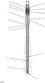
- Figure 1 is the front of the first exemplary medical implant aligned to the bottom right and the back to the top left.
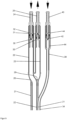
- FIG 5 The front of the second exemplary medical implant is oriented to the bottom left and the back is oriented to the top right.
- the first medical implant according to the invention can have a hollow body 1 made of an elastically or plastically deformable plastic or can have a hollow body 1 whose walls are made of a plastic at least in some areas.
- the hollow body 1 can be a cylinder tube closed on one side.
- the hollow body 1 can, for example, consist of a biocompatible plastic.
- the hollow body 1 can be impermeable to liquids.
- An interior space can be arranged inside the hollow body 1.
- the material used at least in some areas for the hollow body 1 can be permeable to molecular oxygen and carbon dioxide.
- the hollow body 1 or the material from which the hollow body 1 is made can have a permeability coefficient for oxygen of greater than or equal to 0.5 cm 3 / (m 2 *d*bar) and a permeability coefficient for carbon dioxide of greater than or equal to 0. 5 cm 3 /(m 2 *d*bar).
- the permeability coefficient is determined according to DIN 53380-4 (11/2006).
- an interior of the hollow body 1 can be connected to a fluid supply line 2 made of plastic.
- a fluid drain 3 made of plastic.
- the fluid supply line 2 and the fluid discharge line 3 can be flexible and movable at least in some areas.
- the fluid supply line 2 can be on its back (in Figure 1 top left, in the Figures 2 to 4 above) have a connection 4 with which the fluid supply line 2 can be connected to a fluid source (not shown).
- the fluid drain 3 can have a connection 5 on its back, with which the fluid drain 3 can be connected to a receptacle or a drain for used fluid.
- the fluid supply line 2 and the fluid discharge line 3 can be brought together in a connection 6, in which the fluid supply line 2 can be guided coaxially into the fluid discharge line 3 or into the hollow body 1.
- the fluid supply line 2 can be arranged coaxially in the hollow body 1.
- the fluid supply line 2 can be guided in the hollow body 1 almost to the front closed end of the hollow body 1 and there open into the hollow body 1 through an inflow opening 8.
- the fluid supply line 2 can open into the front part of the interior of the hollow body 1 via the inflow opening 8.
- the fluid discharge 3 can be via an outflow opening 9 on the opposite back of the interior of the hollow body 1 be connected to the interior of the hollow body 1. This ensures that the fluid can flow along the surface of the wall of the entire hollow body 1 and thereby a gas exchange of oxygen and carbon dioxide can take place through the wall over the entire length of the hollow body 1.
- the outflow opening 9 can be limited by the connection 6.
- a valve 10 in the form of a lip valve can be arranged in the fluid supply line 2, which allows the fluid to flow in the direction of the hollow body 1 but prevents the fluid from flowing in the direction away from the hollow body 1.
- the valve 10 then acts as a one-way valve.
- a valve 11 in the form of a lip valve can be arranged in the fluid discharge line 3, which prevents the fluid from flowing in the direction of the hollow body 1 but allows the fluid to flow in the direction away from the hollow body 1.
- the valve 11 then acts as a one-way valve.
- the valve 11 in the fluid discharge line 3 can be designed to open from a minimum pressure of the fluid.
- the minimum pressure at the valve 11 in the fluid discharge line 3 is preferably adjustable. The minimum pressure can be chosen so that the pressure of the fluid is sufficient to bring the hollow body 1 into a desired external shape.
- valves 10, 11 can be connected to the fluid supply line 2 and the fluid discharge line 3 via valve housings 12, 13.
- the fluid supply line 2 can be plugged onto the valve housing 12 and, if necessary, additionally fastened.
- the fluid discharge line 3 can be plugged into the valve housing 13 and, if necessary, additionally fastened there.
- connection 4 can be in the form of a Luer lock adapter.
- connection 5 can have the shape of a Luer lock adapter on its back.
- the fluid can be fed in and drained away through the connections 4, 5.
- the connections 4, 5 can be screwed into the valve housings 12, 13.
- the valve housing 12 can be constructed in two parts to fix the valve 10.
- the valve housing 12 can be connected to an external thread of the connection 4 via an internal thread.
- the valve housing 13 can be constructed in two parts to fix the valve 11.
- the valve housing 13 can be connected to an external thread of the connection 5 via an internal thread. All connections can be gas-tight and pressure-tight.
- the fluid supply line 2 can be plugged onto the valve housing 12. It can be provided that the fluid supply line 2 is fastened there in a pressure-tight and gas-tight manner using a crimp sleeve (not shown).
- the fluid discharge line 3 can be plugged onto the valve housing 13. It can be provided that the fluid discharge line 3 is fastened there in a pressure-tight and gas-tight manner using a crimp sleeve (not shown).
- the hollow body 1 can be placed in a cavity.
- the hollow body 1, or the medical implant can thus mechanically support the cavity and stabilize.
- the hollow body 1 can be compressed by applying a negative pressure, for example by evacuating it.
- the hollow body 1 can then be easily removed from the cavity again.
- the cavity is a cavity in a bone, this bone defect can be treated gently.
- the hollow body 1 can also be degraded within the body if it is made of a biodegradable material.
- the fluid can be fed into the medical implant through connection 4 (as in the Figures 1 , 2 and 4 indicated by the pointed arrow pointing into connection 4).
- the fluid can flow through the fluid supply line 2 and open the valve 10 if there is sufficient pressure.
- the fluid can flow through the inflow opening 8 into the hollow body 1 and through the hollow body 1.
- the fluid can flow through the fluid discharge line 3 to the initially closed valve 11. Pressure can build up inside the hollow body 1.
- the valve 11 opens and the fluid can flow out through the fluid discharge line 3 and the connection 5 (as in the Figures 1 , 2 and 4 indicated by the pointed arrow pointing away from connection 5).
- Oxygen is contained in the fluid.
- the fluid can release oxygen into the environment of the hollow body 1 through the wall of the hollow body 1.
- the flowing fluid can absorb carbon dioxide from the environment of the hollow body 1, which diffuses through the wall of the hollow body 1 into the interior, and discharge it from the medical implant through the connection 5.
- the surroundings of the hollow body 1 can be supplied with oxygen and the absorption of carbon dioxide prevents the surroundings of the hollow body 1 from becoming too acidic.
- Sterile filters that are impermeable to germs but permeable to the fluid can be arranged in the fluid supply line 2 and/or in the fluid discharge line 3. This measure can be used without any problems, particularly if the fluid is gaseous. If the fluid is liquid, care must be taken to ensure that the sterile filters do not inhibit the flow of the fluid too much. The fluid can be freed from germs using the sterile filter, which could otherwise get into the hollow body 1 and/or which could be diverted from the hollow body 1 through the connection 5. This reduces the risk of infection of the patient being treated and the treating staff.
- the sterile filter can preferably be arranged in the fluid supply line 2 or the fluid discharge line 3 in the flow direction behind the valve 10 or the valve 11 or the sterile filters can be arranged in the fluid supply line 2 and in the fluid discharge line 3 behind the valves 10, 11.
- Other methods and options for sterilizing the fluid are also possible.
- the fluid can be sterilized with radiation.
- the hollow body 1 and the adjacent areas of the fluid supply line 2 and the fluid discharge line 3 are coated with an antiseptic substance or that a soluble antiseptic substance is contained in the material of the hollow body 1 in order to prevent infection.
- the pointed arrows in Figure 4 inside the cavity 1, the fluid supply line 2 and the fluid discharge line 3 indicate the flow direction of the fluid during operation. Furthermore, the pointed arrows in the area around the cavity 1 indicate the release of oxygen from the fluid.
- the second medical implant according to the invention can have a hollow body 21 made of an elastically or plastically deformable plastic or can have a hollow body 21 whose walls are made of a plastic at least in some areas.
- the hollow body 21 can be a cylinder tube closed on one side.
- the hollow body 21 can consist, for example, of a biocompatible plastic.
- the hollow body 21 can be impermeable to liquids.
- An interior space can be arranged inside the hollow body 21.
- the material used at least in some areas for the hollow body 21 can be permeable to molecular oxygen and carbon dioxide.
- the hollow body 21 or the material from which the hollow body 21 is made can have a permeability coefficient for oxygen of greater than or equal to 0.5 cm 3 / (m 2 *d*bar) and a permeability coefficient for carbon dioxide of greater than or equal to 0. 5 cm 3 /(m 2 *d*bar).
- the permeability coefficient is determined according to DIN 53380-4 (11/2006).
- an interior of the hollow body 21 can be connected to a fluid supply line 22 made of plastic.
- a fluid drain 23 made of plastic.
- the fluid supply line 22 and the fluid discharge line 23 can be flexible and movable at least in some areas.
- the fluid supply line 22 can be on its back (in Figure 5 top right, in the Figures 6 , 7 and 9 above) have a connection 24 with which the fluid supply line 22 can be connected to a fluid source (not shown).
- the fluid drain 23 can have a connection 25 on its back, with which the fluid drain 23 can be connected to a receptacle or a drain for used fluid.
- the fluid supply line 22 and the fluid discharge line 23 can be brought together in a connection 26, in which the fluid supply line 22 can be guided coaxially into the fluid discharge line 23 or into the hollow body 21.
- the fluid supply line 22 can be arranged coaxially in the hollow body 21.
- the fluid supply line 22 can be in the hollow body 21 to be guided almost to the front closed end of the hollow body 21 and open there through an inflow opening 28 into the hollow body 21.
- the fluid supply line 22 can open into the front part of the interior of the hollow body 21 via the inflow opening 28.
- the fluid discharge line 23 can be connected to the interior of the hollow body 21 via an outflow opening 29 on the opposite back of the interior of the hollow body 21. This ensures that the fluid can flow along the surface of the wall of the entire hollow body 21 and thereby a gas exchange of oxygen and carbon dioxide can take place through the wall over the entire length of the hollow body 21.
- the outflow opening 29 can be limited by the connection 26.
- a valve 30 in the form of a lip valve can be arranged in the fluid supply line 22, which allows the fluid to flow in the direction of the hollow body 21 but prevents the fluid from flowing in the direction away from the hollow body 21.
- the valve 30 then acts as a one-way valve.
- a valve 31 in the form of a lip valve can be arranged in the fluid discharge line 23, which prevents the fluid from flowing in the direction of the hollow body 21 but allows the fluid to flow in the direction away from the hollow body 21.
- the valve 31 then acts as a one-way valve.
- the valve 31 in the fluid discharge line 23 can be designed to open from a minimum pressure of the fluid.
- the minimum pressure at the valve 31 in the fluid discharge line 23 is preferably adjustable. The minimum pressure can be selected so that the pressure of the fluid is sufficient to bring the hollow body 21 into a desired external shape.
- valves 30, 31 can be connected to the fluid supply line 22 and the fluid discharge line 23 via valve housings 32, 33.
- the fluid supply line 22 can be plugged onto the valve housing 32 and, if necessary, additionally fastened.
- the fluid discharge line 23 can be plugged into the valve housing 33 and, if necessary, additionally fastened there.
- connection 24 can have the form of a Luer lock adapter on its back.
- connection 25 can have the shape of a Luer lock adapter on its back.
- the fluid can be fed in and drained away through the connections 24, 25.
- the connections 24, 25 can be screwed into the valve housings 32, 33.
- the valve housing 32 can be constructed in two parts to fix the valve 30.
- the valve housing 32 can be connected to an external thread of the connection 24 via an internal thread.
- the valve housing 33 can be constructed in two parts to fix the valve 31.
- the valve housing 33 can be connected to an external thread of the connection 25 via an internal thread. All connections can be gas-tight and pressure-tight.
- the fluid supply line 22 can be plugged onto the valve housing 32. It can be provided that the fluid supply line 22 is pressure-tight there with a crimp sleeve (not shown). is attached gas-tight.
- the fluid discharge line 23 can be plugged onto the valve housing 33. It can be provided that the fluid discharge line 23 is attached there in a pressure-tight and gas-tight manner using a crimp sleeve (not shown).
- the hollow body 21 can be inserted into a cavity.
- the hollow body 21, or the medical implant can thus mechanically support and stabilize the cavity.
- the hollow body 21 can be compressed by applying a negative pressure, for example by evacuating it.
- the hollow body 21 can then be removed from the cavity again.
- the cavity is a cavity in a bone, this bone defect can be treated gently.
- the hollow body 21 can also be degraded within the body if it is made of a biodegradable material.
- the fluid can be fed into the medical implant through the connection 24 (as in the Figures 5 , 6 , 7 and 9 indicated by the pointed arrow pointing into connection 24).
- the fluid can flow through the fluid supply line 22 and open the valve 30 if there is sufficient pressure.
- the fluid can then flow through the inflow opening 28 into the hollow body 21 and through the hollow body 21.
- the fluid can flow through the fluid discharge line 23 to the initially closed valve 31. Pressure can build up inside the hollow body 21.
- the valve 31 opens and the fluid can flow out through the fluid drain line 23 and the connection 25 (as in the Figures 5 , 6 , 7 and 9 indicated by the pointed arrow pointing away from connection 25).
- Oxygen is contained in the fluid.
- the fluid can release oxygen into the environment of the hollow body 21 through the wall of the hollow body 21.
- the flowing fluid can absorb carbon dioxide from the environment of the hollow body 21, which diffuses through the wall of the hollow body 21 into the interior, and discharge it from the medical implant through the connection 25.
- the surroundings of the hollow body 21 can be supplied with oxygen and the absorption of carbon dioxide prevents the surroundings of the hollow body 21 from becoming too acidic.
- Sterile filters that are impermeable to germs but permeable to the fluid can be arranged in the fluid supply line 22 and/or in the fluid discharge line 23. This measure can be used without any problems, particularly if the fluid is gaseous. If the fluid is liquid, care must be taken to ensure that the sterile filters do not inhibit the flow of the fluid too much. The fluid can be freed from germs using the sterile filter, which could otherwise get into the hollow body 21 and/or which could be diverted from the hollow body 21 through the connection 25. This reduces the risk of infection of the patient being treated and the treating staff.
- the sterile filter can preferably be in the Fluid supply line 22 or the fluid discharge line 23 can be arranged behind the valve 30 or the valve 31 in the flow direction or the sterile filters can be arranged in the fluid supply line 22 and in the fluid discharge line 23 behind the valves 30, 31.
- Other methods and options for sterilizing the fluid are also possible.
- the fluid can be sterilized with radiation.
- the hollow body 21 and the adjacent areas of the fluid supply line 22 and the fluid discharge line 23 are coated with an antiseptic substance or a soluble antiseptic substance is contained in the material of the hollow body 21 in order to prevent infection.
- a line 34 with several through openings 36 is attached to the outside of the hollow body 21.
- the line 34 can be connected to an active ingredient supply line 38 that is impermeable to liquids.
- the line 34 and the active ingredient supply line 38 can be provided for introducing liquids to the openings 36.
- the active ingredient supply line 38 can be connected to a source for pharmaceutical active ingredient solutions via a connection 40. As a result, a pharmaceutical active ingredient solution can be delivered to the surface of the line 34 or the hollow body 21.
- a valve 42 can be arranged between the active ingredient supply line 38 and the connection 40.
- Valve 42 is preferably a one-way valve, such as a lip valve.
- the valve 42 can be connected to the active ingredient supply line 38 via a valve housing 44.
- the active ingredient supply line 38 can be plugged onto the valve housing 44 and, if necessary, additionally fastened.
- the connection 40 can have the form of a Luer lock adapter on its back.
- the valve housing 44 can be constructed in two parts to fix the valve 42.
- the valve housing 44 can be connected to an external thread of the connection 40 via an internal thread.
- the active ingredient supply line 38 can be plugged onto the valve housing 44.
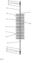
- FIGS. 10 to 13 show illustrations of a third exemplary embodiment of a medical implant according to the invention.
- the third medical implant according to the invention can be a hollow body 51 made of a plastically deformable plastic with incorporated metal wires or a have an incorporated metal grid matrix.
- the hollow body 51 can have a main strand 64 and several branches 66 that are opposite each other in pairs and extend vertically away from the main strand 64.
- the side branches 66 can protrude from the main strand 64 by approximately 2 mm.
- the hollow body 51 can consist, for example, of a biocompatible plastic.
- the hollow body 51 can be impermeable to liquids.
- An interior space can be arranged in the hollow body 51 inside the hollow body 51 and thus also inside the main strand 64 and the branches 66.
- the material used at least in some areas for the hollow body 51 can be permeable to molecular oxygen and carbon dioxide.
- the hollow body 51 or the material from which the hollow body 51 is made can have a permeability coefficient for oxygen of greater than or equal to 0.5 cm 3 / (m 2 *d*bar) and a permeability coefficient for carbon dioxide of greater than or equal to 0. 5 cm 3 /(m 2 *d*bar).
- the permeability coefficient is determined according to DIN 53380-4 (11/2006).
- an interior of the hollow body 51 can be connected to a fluid supply line 52 made of plastic.
- a fluid drain 53 made of plastic.
- the fluid supply line 52 and the fluid discharge line 53 can be flexible and movable at least in some areas.
- the fluid supply line 52 can have a connection 54 with which the fluid supply line 52 can be connected to a fluid source (not shown).
- the fluid discharge line 53 can have a connection 55 with which the fluid discharge line 53 can be connected to a receptacle or a drain for used fluid.
- the fluid supply line 52 and the fluid discharge line 53 can open into the hollow body 51 or the main strand 64 on opposite sides of the hollow body 51.
- the fluid supply line 52 can open into the interior of the hollow body 51 via the inflow opening 58.
- the fluid discharge line 53 can be connected to the interior of the hollow body 51 via an outflow opening 59 on the opposite side of the interior of the hollow body 51. This ensures that the fluid can flow along the surface of the wall of the entire hollow body 51 and thereby a gas exchange of oxygen and carbon dioxide can take place through the wall over the entire length of the hollow body 51 and also in its branches 66.
- a valve 60 in the form of a lip valve can be arranged in the fluid supply line 52, which allows the fluid to flow in the direction of the hollow body 51 but prevents the fluid from flowing in the direction away from the hollow body 51.
- the valve 60 then acts as a one-way valve.
- a valve 61 in the form of a lip valve can be arranged in the fluid discharge line 53, which prevents the fluid from flowing in the direction of the hollow body 51 but allows the fluid to flow in the direction away from the hollow body 51.
- the valve 61 then acts as a one-way valve.
- the valve 61 in the fluid discharge line 53 can be designed to open from a minimum pressure of the fluid.
- the minimum pressure at the valve 61 in the fluid discharge line 53 is preferably adjustable. The minimum pressure can be set so that the pressure of the fluid is sufficient to bring the hollow body 51 into a desired external shape.
- valves 60, 61 can be connected to the fluid supply line 52 and the fluid discharge line 53 via valve housings 62, 63.
- the fluid supply line 52 can be plugged onto the valve housing 62 and, if necessary, additionally fastened.
- the fluid discharge line 53 can be plugged into the valve housing 63 and, if necessary, additionally fastened there.
- connection 54 can have the form of a Luer lock adapter on its back.
- connection 55 can have the shape of a Luer lock adapter on its back.
- the fluid can be fed in and drained through the connections 54, 55.
- the connections 54, 55 can be screwed into the valve housings 62, 63.
- the valve housing 62 can be constructed in two parts to fix the valve 60.
- the valve housing 62 can be connected to an external thread of the connection 54 via an internal thread.
- the valve housing 63 can be constructed in two parts to fix the valve 61.
- the valve housing 63 can be connected to an external thread of the connection 55 via an internal thread. All connections can be gas-tight and pressure-tight.
- the fluid supply line 52 can be plugged onto the valve housing 62. It can be provided that the fluid supply line 52 is fastened there in a pressure-tight and gas-tight manner using a crimp sleeve (not shown).
- the fluid discharge line 53 can be plugged onto the valve housing 13. It can be provided that the fluid discharge line 53 is attached there in a pressure-tight and gas-tight manner using a crimp sleeve (not shown).
- the hollow body 51 can be folded to create a three-dimensional structure (see Figure 11 ). Furthermore, the hollow body 51 can be used to supply and grow cell cultures of bone cells which are arranged on the surface of the hollow body 51. The hollow body 51 prepared in this way can then be introduced into a cavity. The hollow body 51, or the medical implant, can thus mechanically support and stabilize the cavity. When the medical implant is no longer needed, the hollow body 51 can be compressed by applying a negative pressure, for example by evacuating it. The hollow body 51 can then be easily removed from the cavity again. Especially if the cavity is a cavity in a bone, this bone defect can be treated gently.
- the hollow body 51 can also be degraded within the body if it is made of a biodegradable material.
- the fluid can be fed into the medical implant through port 54 (as in the Figures 10 to 13 indicated by the pointed arrow pointing into connection 54).
- the fluid can flow through the fluid supply line 52 and open the valve 60 if there is sufficient pressure.
- the fluid can then flow through the inflow opening 58 into the hollow body 51 and through the main strand 64 and the branches 66 of the hollow body 51.
- the fluid can flow through the fluid discharge line 53 to the initially closed valve 61. Pressure can build up inside the hollow body 51.
- the valve 61 opens and the fluid can flow out through the fluid drain line 53 and the connection 55 (as in the Figures 10 to 13 indicated by the pointed arrow pointing away from connection 55).
- Oxygen is contained in the fluid.
- the fluid can release oxygen into the environment of the hollow body 51 through the wall of the hollow body 51.
- the flowing fluid can absorb carbon dioxide from the environment of the hollow body 51, which diffuses through the wall of the hollow body 51 into the interior, and discharge it from the medical implant through the connection 55.
- the surroundings of the hollow body 51 can be supplied with oxygen and the absorption of carbon dioxide prevents the surroundings of the hollow body 51 from becoming too acidic.
- Sterile filters that are impermeable to germs but permeable to the fluid can be arranged in the fluid supply line 52 and/or in the fluid discharge line 53. This measure can be used without any problems, particularly if the fluid is gaseous. If the fluid is liquid, care must be taken to ensure that the sterile filters do not inhibit the flow of the fluid too much. The fluid can be freed from germs using the sterile filter, which could otherwise get into the hollow body 51 and/or which could be diverted from the hollow body 51 through the connection 55. This reduces the risk of infection of the patient being treated and the treating staff.
- the sterile filter can preferably be arranged in the fluid supply line 52 or the fluid discharge line 53 in the flow direction behind the valve 60 or the valve 61 or the sterile filters can be arranged in the fluid supply line 52 and in the fluid discharge line 53 behind the valves 60, 61.
- Other methods and options for sterilizing the fluid are also possible.
- the fluid can be sterilized with radiation.
- the hollow body 51 and, if appropriate, the adjacent areas of the fluid supply line 52 and the fluid discharge line 53 are coated with an antiseptic substance or a soluble antiseptic substance is contained in the material of the hollow body 51 in order to prevent infection.
- the pointed arrows in Figure 12 inside the cavity 51, the fluid supply line 52 and the fluid discharge line 53 indicate the flow direction of the fluid during operation. Furthermore, the pointed arrows in the area around the cavity 51 indicate the release of oxygen from the fluid.
- the medical implant can be used extracorporeally to ventilate and multiply a cell culture for bone cells on the surface of the hollow body 1, 21, 51. Provided with the grown cell culture, the medical implant can then be implanted and then ventilated further inside the body in order to promote further proliferation and growth of the cells in the bone defect.
Landscapes
- Health & Medical Sciences (AREA)
- Orthopedic Medicine & Surgery (AREA)
- Life Sciences & Earth Sciences (AREA)
- Transplantation (AREA)
- Public Health (AREA)
- General Health & Medical Sciences (AREA)
- Biomedical Technology (AREA)
- Heart & Thoracic Surgery (AREA)
- Veterinary Medicine (AREA)
- Engineering & Computer Science (AREA)
- Animal Behavior & Ethology (AREA)
- Oral & Maxillofacial Surgery (AREA)
- Cardiology (AREA)
- Vascular Medicine (AREA)
- Neurology (AREA)
- Surgery (AREA)
- Physical Education & Sports Medicine (AREA)
- Gastroenterology & Hepatology (AREA)
- Pulmonology (AREA)
- Nuclear Medicine, Radiotherapy & Molecular Imaging (AREA)
- Medical Informatics (AREA)
- Molecular Biology (AREA)
- Prostheses (AREA)
- Materials For Medical Uses (AREA)
Description
- Die Erfindung betrifft ein medizinisches Implantat zur Behandlung von Knochendefekten sowie ein Knochendefektbehandlungssystem aufweisend ein solches Implantat. Die Erfindung betrifft auch ein Verfahren zum Begasen einer Oberfläche eines medizinischen Implantats. Gegenstand der Erfindung ist somit ein medizinisches Implantat zur temporären Implantation in Knochenkavitäten.
- Knochendefekte können beim Menschen vielfältige Ursachen haben. Häufige Ursachen sind Traumata und Infektionen. Knochendefekte heilen spontan nicht aus, wenn sie eine kritische Größe überschreiten. Es liegt dann ein sogenannter "critical-size-defect" vor. Zur Behandlung von Knochendefekten werden Knochenersatzmaterialien unterschiedlichster Struktur und Zusammensetzung, sowie allogenes Knochengewebe und autologes Knochengewebe klinisch eingesetzt.
- Knochenersatzmaterialien sind seit Jahrzehnten bekannt und können aus unterschiedlichsten Materialien gefertigt sein. Typische anorganische Knochenersatzmaterialien sind Calciumsulfat (H. Dreesmann: Über Knochenplombierung. Klinische Chirurgie (1892) 804-810), Carbonatapatit (M. V. Vallet-Regi, J. M. Gonzalez-Cabbet: Calciumphosphates as substitution of bone tissues. Progress in Solid State Chemistry 32 (1-2) (2004)1-31), Hydroxylapatit, β-Tricalciumphosphat (R.W. Bucholz, A. Carlton, R. E. Holmes: Hydroxyapatite and tricalciumphosphate bone graft substitutes. The Orthopedic Clinics of North America 18(2) (1987) 323-334), Biogläser (H. Oonishi et al.: Particulate bioglass compared with hydroxyapatite as bone graft substitute. Clinical Orthopaedics and Related Research 334(1997) 316-325) und demineralisierte Knochenmatrix (M. E. Bolander, G. Balian: The use of demineralized bone matrix in the repair of segmental defects. Augmentation with extracted matrix proteins and comparison with autologous grafts. The Journal of bone and Joint Surgery Amercian Volume 68(8) 1986) 1264-1274). Daneben wurden auch Knochenersatzwerkstoffe auf organischer Basis, wie zum Beispiel Polyester, und auch Kombinationen aus anorganischen und organischen Werkstoffen für die Herstellung von Knochenersatzmaterialein eingesetzt (S. Higashi et al.: Polymer-hydroxyapatite composites for biodegradable bone fillers. Biomaterials 7(3) (1986) 183-187)
- Die
US 2001/0004710 A1 offenbart einen Platzhalter zum Behandeln einer Kavität eines Patienten, bei dem ein Ballon aufgeblasen werden kann und in den Ballon ein härtbares Biomaterial eingespeist werden kann. Ein Gasaustausch ist nicht vorgesehen. In dem Artikel "Gas Permeability of Thermoplastic Polyurethane Elastomers" von Katuji Matsunaga et a. in Polymer Jounal Vol. 37, No. 6, Seiten 413-417 (2205) ist ein Kunststoff bekannt, der für Sauerstoff und CO2 durchlässig ist. - Im Dentalbereich werden Knochenersatzmaterialien mit Erfolg bei relativ kleinvolumigen Knochendefekten eingesetzt. Bei größeren Knochendefekten im Bereich der Extremitäten wird sehr häufig klinisch beobachtet, dass auch bei Verwendung von porösen Knochenersatzmaterialien das Knochengewebe nur oberflächlich in das Knochenersatzmaterial einwächst. Ähnliche Probleme treten bei der Transplantation von autologem Knochengewebe und auch bei Kombinationen von autologem Knochenmaterial und anorganischen Knochenersatzmaterialien auf. Das autologe Gewebe, das sich am weitesten vom gut durchbluteten Knochengewebe entfernt befindet, ist häufig geschädigt und stirbt vielfach ab.
- Die der vorliegenden Erfindung zugrundeliegende Aufgabe kann also darin gesehen werden, eine Möglichkeit zu finden und gegebenenfalls ein medizinisches Implantat bereitzustellen, mit dem die Heilungschancen verbessert werden. Die Stabilisation und die Ossifikation des Knochendefekts sollen so schnell wie möglich und so unkompliziert wie möglich erreicht werden. Dabei können auch weitere Hilfsmittel eingesetzt, die den Heilungsprozess positiv beeinflussen.
- Es wurde im Rahmen der vorliegenden Erfindung gefunden, dass ein wesentlicher Grund für die Beobachtung, dass autologes Gewebe, das sich am weitesten vom gut durchbluteten Knochengewebe entfernt befindet, häufig geschädigt ist und vielfach abstirbt, sehr wahrscheinlich darin begründet ist, dass diese Bereiche nicht mehr ausreichend mit Sauerstoff versorgt werden können und dass ein Abtransport des beim Stoffwechsel entstehenden Kohlendioxids und weiterer Stoffwechselprodukte nur erschwert möglich ist, weil keine Blutgefäße im Inneren des Knochenersatzmaterials vorhanden sind, bei denen das strömende Blut den Sauerstoff-Transport und den Abtransport des gebildeten Kohlendioxids gewährleistet.
- Die Aufgabe der Erfindung besteht somit in der Entwicklung eines temporären medizinischen Implantats, das einen Gasaustausch mit seiner Umgebung ermöglichen soll. Das Implantat soll in der Lage sein, Sauerstoff an seiner Oberfläche an die Umgebung abzugeben und Kohlendioxid aus der Umgebung aufzunehmen und abzutransportieren. Die Abgabe des Sauerstoffs und die Aufnahme sollen kontinuierlich oder auch diskontinuierlich möglich sein. Der Gasaustausch und der Gastransport sollen durch ein Fluid erreicht werden, welches durch das medizinische Implantat strömen soll. Das medizinische Implantat soll explantierbar sein und soll nicht mit humanem oder tierischem Gewebe verwachsen können. Das temporäre medizinische Implantat soll einen Gasaustausch mit umgebenden Knochenersatzmaterialien und insbesondere mit autologem Knochengewebe und auch mit Zellen, wie Osteoblasten, besiedelten Knochenersatzmaterialien ermöglichen. Dadurch sollen die Zellen, insbesondere die Osteoblasten, nach ihrer Implantation in einen größeren Knochendefekt so lange am Leben erhalten werden, bis eine Versorgung der Zellen mit Sauerstoff durch neu gebildete Blutgefäße möglich ist. Sobald diese vom Organismus ausgebildet sind, soll das temporäre Implantat entfernt werden können.
- Eine weitere Aufgabe der Erfindung ist die Entwicklung eines Knochenersatzmaterialsystems, das das zu entwickelnde temporäre medizinische Implantat als Bestandteil enthält.
- Eine zusätzliche Aufgabe der vorliegenden Erfindung ist es auch, ein nicht medizinisches Verfahren zu entwickeln, mit dem Sauerstoff in einen Hohlraum abgegeben werden kann und gleichzeitig Kohlendioxid aus dem Hohlraum aufgenommen werden kann. Das Verfahren soll mit dem erfindungsgemäßen medizinischen Implantat durchführbar sein und in Hohlräumen angewendet werden, die kein Teil eines menschlichen oder tierischen Körpers sind.
- Das medizinische Implantat ist neben seiner Platzhaltungsfunktion auch zum Gasaustausch mit dem umliegenden Gewebe bestimmt, wobei Sauerstoff oder ein Sauerstoff enthaltendes Spülgasgemisch oder eine mit Sauerstoff angereicherte Spülflüssigkeit als Fluid den Innenraum des Abstandhalters kontinuierlich oder diskontinuierlich durchströmt und über die permeable Außenwand des Implantats dem Gewebe Sauerstoff zugeführt und gleichzeitig Kohlendioxid abgeführt werden kann.
- Die Aufgaben der Erfindung werden gelöst durch ein medizinisches Implantat zur Behandlung von Knochendefekten aufweisend mindestens einen Hohlkörper, der einen Innenraum im Inneren des Hohlkörpers begrenzt, eine Fluidzuleitung, die mit dem Innenraum des Hohlkörpers fluiddurchlässig verbunden ist, eine Fluidableitung, die mit dem Innenraum des Hohlkörpers fluiddurchlässig verbunden ist, wobei der Hohlkörper zumindest bereichsweise oder vollständig aus zumindest einem Kunststoff besteht, wobei der zumindest eine Kunststoff für Flüssigkeiten undurchlässig ist und für Sauerstoff und für Kohlendioxid durchlässig ist, so dass Sauerstoff aus einem durch den Hohlkörper geleiteten Fluid an die Umgebung des Hohlkörpers abgebbar ist und Kohlendioxid aus der Umgebung des Hohlkörpers in das Fluid aufnehmbar ist, wobei der Hohlkörper oder der zumindest eine Kunststoff des Hohlkörpers einen Permeabilitätskoeffizienten für Sauerstoff von größer oder gleich 0,5 cm3/(m2*d*bar) und einen Permeabilitätskoeffizienten für Kohlendioxid von größer oder gleich 0,5 cm3/(m2*d*bar) aufweist.
- Bevorzugt ist das medizinische Implantat ein temporäres medizinisches Implantat.
- Das durch den Hohlkörper geleitete Fluid muss zur Abgabe von Sauerstoff und zur Aufnahme von Kohlendioxid geeignet sein.
- Bevorzugt kann vorgesehen sein, dass das medizinische Implantat zur temporären Implantation in Knochenkavitäten geeignet ist.
- Bevorzugt kann auch vorgesehen sein, dass der Hohlkörper aus einem für Sauerstoff und Kohlendioxid permeablen Kunststoff gefertigt ist.
- Bevorzugt kann ferner vorgesehen sein, dass der Innenraum zur Umgebung des medizinischen Implantats abgeschlossen ist.
- Der zumindest eine Kunststoff bildet bevorzugt zumindest bereichsweise eine durchgehende Wandung des Hohlkörpers. Das heißt, dass es Bereiche der Wandung des Hohlkörpers gibt, in denen außer dem zumindest einen Kunststoff aus keinem anderen zusätzlichen Material besteht. Gut durchlässige Netze und Drähte, insbesondere aus Metall, stören dabei nicht. Hierdurch soll sichergestellt werden, dass die Durchlässigkeit des Kunststoffs für Sauerstoff und Kohlendioxid dazu genutzt werden kann, dass die Wandung des Hohlkörpers zumindest in diesen Bereichen ebenfalls für Sauerstoff und Kohlendioxid durchlässig ist.
- Bevorzugt kann also vorgesehen sein, dass eine den Innenraum des Hohlkörpers begrenzende Wandung für Sauerstoff und Kohlendioxid durchlässig ist.
- Gemäß einer bevorzugten Ausführung der vorliegenden Erfindung kann vorgesehen sein, dass der Hohlkörper röhrenförmig ausgebildet ist, wobei die Fluidzuleitung und die Fluidableitung bevorzugt an einer Stirnseite des Hohlkörpers mit dem Hohlkörper verbunden sind oder an zwei einander gegenüberliegenden Stirnseiten des Hohlkörpers mit dem Innenraum des Hohlkörpers verbunden sind. Röhrenförmige Hohlkörper sind als Abstandshalter insbesondere bei Knochendefekten der langen Röhrenknochen besonders gut geeignet.
- Der Hohlkörper kann auch jede andere beliebige Gestalt aufweisen, je nach der Größe und Gestalt des temporär auszufüllenden Knochendefekts.
- Das Fluid kann gasförmig oder auch flüssig sein. Es sind auch Gemische aus Flüssigkeiten und Gasen möglich. Als Fluide werden Luft, Sauerstoff, mit Sauerstoff gesättigte Kochsalzlösung, mit Sauerstoff gesättigte Ringer-Lösung, mit Sauerstoff gesättigte Ringer-Lactat-Lösung, mit Sauerstoff gesättigte Phosphatpufferlösung und mit Sauerstoff gesättigtes Perfluordecalin sowie deren Gemische bevorzugt. Wesentlich ist, dass das Fluid Sauerstoff enthält und dass das Fluid Kohlendioxid aufnehmen kann. Es sind daher alle Fluide geeignet, die Sauerstoff und Kohlendioxid transportieren können und diese Stoffe über die permeable Wand des Hohlkörpers mit der Umgebung austauschen können.
- Es ist erfindungsgemäß vorgesehen, dass der Hohlkörper oder der zumindest eine Kunststoff des Hohlkörpers einen Permeabilitätskoeffizienten für Sauerstoff von größer oder gleich 0,5 cm3/(m2*d*bar) und einen Permeabilitätskoeffizienten für Kohlendioxid von größer oder gleich 0,5 cm3/(m2*d*bar) aufweist, bevorzugt einen Permeabilitätskoeffizienten für Sauerstoff von größer oder gleich 1 cm3/(m2*d*bar) und einen Permeabilitätskoeffizienten für Kohlendioxid von größer oder gleich 1 cm3/(m2*d*bar) aufweist.
- Hierdurch kann eine gute Versorgung der Umgebung des medizinischen Implantats mit Sauerstoff und ein guter Abtransport von Kohlendioxid von der Umgebung des medizinischen Implantats erfolgen und dabei von der Innenseite der Behandlungssituation aus erfolgen.
- Der Permeabilitätskoeffizient wird nach DIN 53380-4 (11/2006) bestimmt. Diese betrifft insbesondere die Prüfung von Kunststoffen, hier die Bestimmung der Gasdurchlässigkeit, wobei im Teil 4 der DIN 53380 ein Kohlenstoffdioxid-spezifisches Infrarotabsorptions-Verfahren zur Messung an Kunststoff-Folien und Kunststoff-Formteilen standardisiert wird, das auch auf Sauerstoff übertragbar ist. Derartige Messungen werden beispielsweise von der Firma Mecadi GmbH (Bexbach, Deutschland) durchgeführt und angeboten.
- Es kann also bevorzugt vorgesehen sein, dass der Hohlkörper oder der zumindest eine Kunststoff des Hohlkörpers einen Permeabilitätskoeffizienten für Sauerstoff von größer oder gleich 0,5 cm3/(m2*d*bar) und einen Permeabilitätskoeffizienten für Kohlendioxid von gleich/größer 0,5 cm3/(m2*d*bar) gemäß DIN 53380-4 (11/2006) aufweist, bevorzugt einen Permeabilitätskoeffizienten für Sauerstoff von größer oder gleich 1 cm3/(m2*d*bar) und einen Permeabilitätskoeffizienten für Kohlendioxid von größer oder gleich 1 cm3/(m2*d*bar) gemäß DIN 53380-4 (11/2006) aufweist.
- Permeabilität bezeichnet allgemein bei Festkörpern die Eigenschaft, Gase und/oder Flüssigkeiten passieren zu lassen. Vorliegend bezieht sich dies auf die Permeabilität der Wandungen des Hohlkörpers und dies bezogen auf molekularen Sauerstoff und molekulares Kohlendioxid in gasförmiger Form. Der Permeabilitätskoeffizient ist eine materialspezifische Konstante und ist ein Maß der Durchlässigkeit für Flüssigkeiten und Gase.
- Die Einheit d steht für einen Tag (day).
- Es kann ferner vorgesehen sein, dass die Fluidzuleitung und die Fluidableitung derart in den Hohlkörper münden, dass bei einem Durchströmen des Fluids aus der Fluidzuleitung durch den Hohlkörper in die Fluidableitung das Fluid über eine gesamte Innenfläche des Hohlkörpers strömt oder zumindest über 50% der gesamten Innenfläche des Hohlkörpers strömt.
- Hierdurch wird beim Durchströmen des Hohlkörpers ein ausreichend langer Kontakt des durchströmenden Fluids mit der Innenwand des Hohlkörpers beziehungsweise des zumindest einen Kunststoffs erreicht, wodurch ein Gasaustausch von Sauerstoff und Kohlendioxid durch die Wand des Hohlkörpers oder des zumindest einen Kunststoffs begünstigt wird.
- Wenn der Hohlkörper mit einem Hauptstrang und mit mehreren sich vom Hauptstrang weg erstreckenden Ästen aufgebaut ist, so gelten auch die Äste als Teil der überströmten Oberfläche, auch wenn sich der Hauptteil der Strömung des Fluids entlang des Hauptstrangs an den Ästen vorbei bewegt. Maßgeblich ist hier, dass die inneren Oberflächen der Äste ausgehend vom Hauptstrom des Fluids aus zugänglich sind.
- Des Weiteren kann vorgesehen sein, dass eine Einströmöffnung der Fluidzuleitung, mit der die Fluidzuleitung in den Innenraum mündet, räumlich getrennt von einer Ausströmöffnung der Fluidableitung angeordnet ist, wobei die Ausströmöffnung die Einmündung des Innenraums in die Fluidableitung bildet.
- Dadurch wird ein Gasaustausch über die gesamte Wandung des Hohlkörpers oder über große Bereiche der Wandung des Hohlkörpers gewährleistet. Die Einströmöffnung ist die Öffnung der Fluidzuleitung, durch die das Fluid aus der Fluidzuleitung in den Innenraum des Hohlkörpers einströmt. Dementsprechend ist die Ausströmöffnung die Öffnung der Fluidableitung, durch die das Fluid in den Fluidableitung aus dem Innenraum des Hohlkörpers ausströmt.
- Dabei kann vorgesehen sein, dass die Einströmöffnung der Fluidzuleitung an einem ersten Ende des Hohlkörpers angeordnet ist und die Ausströmöffnung an einem dem ersten Ende gegenüberliegenden zweiten Ende des Hohlkörpers angeordnet ist.
- Dadurch wird die Verweilzeit des durchströmenden Fluids an der Innenwand des Hohlkörpers beziehungsweise an der Innenwand des zumindest einen Kunststoffs vergrößert und der Gasaustausch durch den Hohlkörper oder den zumindest einen Kunststoff verbessert.
- Ferner kann vorgesehen sein, dass die Fluidzuleitung und die Fluidableitung beide gemeinsam auf einer Seite des Hohlkörpers mit dem Hohlkörper verbunden sind.
- Dadurch wird das Einsetzen des Implantats in die Kavität im Knochen des Patienten vereinfacht. Zudem gibt es im Idealfall nur dicht beieinander liegende Zugänge zum Hohlkörper und zur Behandlungssituation, wodurch die Gefahr der mikrobiellen Verkeimung vermindert wird.
- Gemäß einer weiteren Ausführung der vorliegenden Erfindung kann vorgesehen sein, dass in der Fluidzuleitung und/oder der Fluidableitung ein keimundurchlässiger aber für Gase durchlässiger Sterilfilter angeordnet ist.
- Hierdurch wird die Gefahr einer Infektion des behandelten Patienten und des behandelnden Personals reduziert.
- Gemäß einer bevorzugten Ausführung der vorliegenden Erfindung kann vorgesehen sein, dass in der Fluidzuleitung und/oder der Fluidableitung ein Ventil angeordnet ist, insbesondere ein Einwegventil angeordnet ist, wobei das Einwegventil vorzugsweise ein Rückschlagventil ist.
- Durch die Verwendung eines Einwegventils oder eines Rückschlagventils ist ein Rückstrom des Fluids sicher ausgeschlossen. Zudem kann mit einem geeigneten einstellbaren Ventil der Druck im Inneren des Hohlkörpers eingestellt werden und so eine bestimmte Form oder eine bestimmte Steifigkeit des medizinischen Implantats erreicht werden.
- Gemäß einer bevorzugten Weiterbildung kann vorgesehen sein, dass das Ventil in der Fluidableitung angeordnet ist und als Überdruckventil ausgebildet ist, wobei vorzugsweise der Öffnungsdruck des Überdruckventils einstellbar ist.
- Dadurch kann der expandierte Zustand des Hohlkörpers sicher erreicht und auch gehalten werden.
- Durch ein Einwegventil in der Fluidableitung kann erreicht werden, dass mit dem Fluid ein Druck im Inneren des Hohlkörpers aufgebaut werden kann und dass das verwendete Fluid nicht in den Hohlkörper zurück gelangen kann. Es kann demzufolge besonders bevorzugt vorgesehen sein, dass in der Fluidableitung ein Einwegventil angeordnet ist.
- Es kann auch vorgesehen sein, dass die Fluidzuleitung und die Fluidableitung aus einem für Sauerstoff und Kohlendioxid nicht durchlässigen Material bestehen, vorzugsweise aus einem für Sauerstoff und Kohlendioxid nicht durchlässigen Kunststoff bestehen.
- Hierdurch wird verhindert, dass der Sauerstoff zu früh aus dem Fluid austritt. Zudem können die Fluidzuleitung und die Fluidableitung so aus einem kostengünstigeren Kunststoff gefertigt werden.
- Ferner kann vorgesehen sein, dass der Hohlkörper oder der zumindest eine Kunststoff des Hohlkörpers mindestens einen antiseptischen Wirkstoff enthält oder mit mindestens einem antiseptischen Wirkstoff beschichtet ist.
- Hierdurch können die Oberfläche des medizinischen Implantats und die Umgebung des medizinischen Implantats im Körper des Patienten mit dem mindestens einen antiseptischen Wirkstoff desinfiziert werden. Hierdurch werden Komplikationen bei der Behandlung vermieden.
- Des Weiteren kann vorgesehen sein, dass der Hohlkörper ein Hohlzylinder ist oder der Hohlkörper einen Hauptstrang in Form eines Hohlzylinders aufweist, wobei die Fluidzuleitung und die Fluidableitung im Bereich gegenüberliegender Grundflächen des Hohlzylinders in den Hohlzylinder münden, wobei vorzugsweise der Hohlzylinder einen Teil der Fluidzuleitung oder der Fluidableitung koaxial umgibt.
- Durch die zylindrische Form kann das Implantat in Knochendefekte von Röhrenknochen eingebracht werden. Zudem kann so sichergestellt werden, dass das Fluid über eine möglichst große Oberfläche der Wandung des Hohlkörpers fließt, so dass der Gasaustausch unterstütz wird.
- Bevorzugt kann ferner vorgesehen sein, dass der Hohlkörper als perforierter Metallkörper oder Kunststoffkörper ausgeführt ist, dessen Außenseite mit einer für Sauerstoff und für Kohlendioxid permeablen Kunststoffschicht überdeckt ist.
- Dadurch ist es möglich, ein mechanisch belastbares medizinisches Implantat herzustellen und gleichzeitig den Gasaustausch durch die Wandung des Hohlkörpers zu gewährleisten.
- Zur Verbesserung der Formbarkeit des Hohlkörpers kann vorgesehen sein, dass der Hohlkörper einen für Sauerstoff und Kohlendioxid permeablen und plastisch verformbaren Kunststoffmantel aufweist, wobei vorzugsweise der Kunststoffmantel spiralförmige und/oder netzartig angeordnete Metalldrähte enthält.
- Dadurch kann das medizinische Implantat je nach anatomischen Gegebenheiten geformt werden und behält gegebenenfalls auf Grund der Steifheit der Metalldrähte die gewählte Form bei.
- Um zusätzliche Behandlungsmöglichkeiten zu eröffnen kann vorgesehen sein, dass am Hohlkörper eine Leitung mit mehreren Öffnungen zur Abgabe eines Wirkstoffs angeordnet ist, wobei die Leitung mit einer Wirkstoffzuleitung verbunden ist, wobei bevorzugt die Summe der freien Querschnittsflächen der Öffnungen kleiner ist als der freie Querschnitt der Leitung und der Wirkstoffzuleitung.
- Mit dieser Ausgestaltungsform ist es möglich, lokal pharmazeutische Wirkstofflösungen zu applizieren. Als pharmazeutische Wirkstoffe kommen hierbei Antibiotika, Antiseptika, Antiphlogistika, Bisphosphonate, Wachstumsfaktoren, Bakteriophagen, Lysostaphin und Muramidasen in Betracht. Daneben ist es auch möglich, Zellsuspensionen durch die Wirkstoffzuleitung in die Umgebung des Implantats einzubringen und eine Besiedlung der das medizinische Implantat umgebenen Strukturen zu ermöglichen.
- Durch die Leitung mit den Öffnungen ist es auch möglich, antiseptische oder antibiotische Lösungen durch die Öffnungen zur Umgebung des medizinischen Implantats zu pressen. Durch die Leitung ist auch ein antimikrobieller Schutz der Oberfläche des medizinischen Implantats möglich. Es ist auch möglich, durch die Leitung flüssige oder gelartige antibiotische oder antiseptische pharmazeutische Zubereitungen einzubringen, die durch Diffusion in die Umgebung migrieren können und so zur Behandlung des Patienten im Bereich des medizinischen Implantats verwendet werden können.
- Es kann auch vorgesehen sein, dass der zumindest eine Kunststoff ein elastischer und/oder plastischer, nicht biodegradierbaren Kunststoff ist, wobei bevorzugt der zumindest eine Kunststoff ausgewählt ist aus Polyurethan, Ethylen-Propylen-Dien-Kautschuk EPDM und Silikon, oder der zumindest eine Kunststoff ein elastischer und/oder plastischer, biodegradierbaren Kunststoff ist, wobei bevorzugt der zumindest eine Kunststoff ausgewählt ist aus Gelatine, vernetztem Kollagen und vernetztem Albumin.
- Durch diese beiden Möglichkeiten kann ein gut wieder entfernbares medizinisches Implantat bereitgestellt werden (nicht biodegradierbarer Kunststoff) oder das medizinische Implantat kann teilweise oder vollständig im Körper abgebaut werden (biodegradierbarer Kunststoff) und muss nicht oder nicht vollständig wieder entfernt werden.
- Des Weiteren kann vorgesehen sein, dass der Hohlkörper durch Änderung des Drucks in seinem Innenraum gegenüber der umgebenden Atmosphäre expandierbar und/oder zusammenziehbar ist.
- Bei der Verwendung von eines nicht formstabilen, elastischen Implantatmaterials kann die gewählte Gestalt des Hohlkörpers durch einen geeigneten Innendruck des Hohlkörpers gewährleistet werden. Zudem können das Einsetzen und das Entfernen des medizinischen Implantats so vereinfacht werden.
- Gemäß einer bevorzugten Variante der vorliegenden Erfindung kann auch vorgesehen sein, dass der Hohlkörper einen Hauptstrang und mehrere seitlich davon abgehende Äste aufweist, wobei der Innenraum des Hohlkörpers sich im Hauptstrang und in den Ästen erstreckt und die Fluidzuleitung und die Fluidableitung mit dem Hauptstrang verbunden sind, wobei vorzugsweise zumindest die Äste oder Wandungen der Äste aus dem Kunststoff bestehen oder mit dem Kunststoff aufgebaut sind.
- Bevorzugt weist der Innenraum in den Ästen einen geringeren Querschnitt auf als in dem Hauptstrang.
- Hierdurch kann die Oberfläche des Hohlkörpers vergrößert werden und so eine größere Menge von Zellen versorgt werden, insbesondere extrakorporal versorgt werden.
- Ferner kann vorgesehen sein, dass der Hohlkörper aus zumindest einem resorbierbaren und/oder biodegradierbaren Material besteht.
- Hierdurch kann der Hohlkörper im Körper verbleiben und dort abgebaut werden, ohne dass er wieder aus dem Körper entfernt werden muss. Die Fluidzuleitung und die Fluidableitung können hierzu einfach abgetrennt werden.
- Diese Varianten ermöglichen die extrakorporale Vermehrung von Zellen in Hohlräumen von Zellkulturgefäßen. Als wachstumsfördernde Substanzen kommt beispielsweise Tricalciumphosphat oder ähnlich wirkende Substanzen in Frage. Die so vermehrten Zellen können dann zusammen mit dem medizinischen Implantat oder auch ohne das medizinische Implantat implantiert werden. Wenn der Hohlkörper aus einer vernetzten Gelatine oder Biopolymeren aufgebaut wird, kann das medizinische Implantat bis auf die Anschlüsse abbaubar sein. Das Gleiche ist auch möglich, wenn der Hohlkörper aus abbaubaren Hohlfasern aufgebaut ist.
- Es kann vorgesehen sein, dass der Hohlkörper oder das gesamte medizinische Implantat als dreidimensionale Struktur faltbar ist. Hierdurch kann das medizinische Implantat an die Form der zu behandelnden Kavität anpassbar gestaltet werden.
- Das medizinische Implantat kann als belüftbares Scaffold zur Zellkultivierung verwendet werden. Ein "Scaffold" bezeichnet im Tissue Engineering (TE) (engl. für Gewebekonstruktion bzw. Gewebezüchtung) einen Überbegriff für die künstliche Herstellung von biologischem Gewebe durch eine gerichtete Kultivierung von Zellen, um damit kranke Gewebe bei einem Patienten zu ersetzen oder zu regenerieren. Hierfür ist keine medizinische Behandlung eines Patienten erforderlich, da diese erst später erfolgt mit Hilfe der künstlich hergestellten Zellen. Das medizinische Implantat kann dann als Trägerstruktur für Zellkulturen verwendet werden. Die der vorliegenden Erfindung zugrundeliegenden Aufgaben werden auch gelöst durch ein Knochendefektbehandlungssystem aufweisend ein solches erfindungsgemäßes medizinisches Implantat und das Fluid, wobei das Fluid Sauerstoff enthält und zur Aufnahme von Kohlendioxid geeignet ist.
- Hierdurch wird ein vollständiges System (Knochendefektbehandlungssystem) bereitgestellt, bei dem das Fluid bereits auf das medizinische Implantat beziehungsweise beide auf die Behandlungssituation abgestimmt sein kann.
- Dabei kann vorgesehen sein, dass das Fluid ausgewählt ist aus Luft, Sauerstoff, mit Sauerstoff gesättigter Kochsalzlösung, mit Sauerstoff gesättigter Ringer-Lösung, mit Sauerstoff gesättigter Ringer-Lactat-Lösung, mit Sauerstoff gesättigter Phosphatpufferlösung und mit Sauerstoff gesättigtem Perfluordecalin oder einem Gemisch aus zumindest zwei der genannten Gase oder Flüssigkeiten.
- Diese Fluide sind gut zur Abgabe von Sauerstoff und zur Aufnahme von Kohlendioxid geeignet. Zudem sind viele dieser Fluide gesundheitlich unbedenklich.
- Es ist vorgesehen, dass das Knochendefektbehandlungssystem ein Knochenersatzmaterial aufweist, wobei das Knochenersatzmaterial auf der äußeren Oberfläche des Hohlkörpers aufgetragen ist oder auf die äußere Oberfläche des Hohlkörpers aufbringbar ist.
- Hiermit wird ein weiter vervollständigtes Knochendefektbehandlungssystem bereitgestellt, das alle Bestandteile enthält, die zur Behandlung eines Knochendefekts notwendig und hilfreich sind.
- Dabei kann wiederum vorgesehen sein, dass das Knochenersatzmaterial ausgewählt ist aus einem nicht biodegradierbaren, einem teildegradierbaren, einem vollständig biodegradierbaren Knochenersatzmaterial und deren Mischungen.
- Diese Mischungen sind besonders gut mit dem erfindungsgemäßen medizinischen Implantat einsetzbar.
- Des Weiteren kann vorgesehen sein, dass das Knochenersatzmaterial ausgewählt ist aus autologem Knochengewebe, allogenem Knochengewebe, Hydroxylapatit, Carbonatapatit, β-Tricalciumphosphat, α-Tricalciumphosphat, Calcium-Dihydrat, Brushit, Monetit und deren Mischungen, oder das Knochenersatzmaterial lebende Zellen enthält und/oder mit lebenden Zellen auf seiner Oberfläche besiedelt ist.
- Diese Knochenersatzmaterialien lassen sich besonders gut mit dem erfindungsgemäßen medizinischen Implantat verwenden. Eine Versorgung dieser Knochenersatzmaterialien mit Sauerstoff und eine Entsäuerung durch Kohlendioxidaufnahme wirken sich bei diesen Knochenersatzmaterialien besonders gut für die Behandlungssituation aus.
- Es ist besonders vorteilhaft, wenn das medizinische Implantat mit autologem Knochengewebe und besonders bevorzugt mit autologer Spongiosa kombiniert wird. Durch den Sauerstoffeintrag über den Hohlkörper werden die Zellen des autologen Knochengewebes mit Sauerstoff versorgt und gleichzeitig wird das beim Stoffwechsel der Zellen freigesetzte Kohlendioxid abgeführt. Sauerstoffmangel kann zur Behinderung der Atmung der Zellen führen, so dass diese zuerst beginnen zu gären und dann abzusterben. Gärungsprozesse können eine lokale Übersäuerung bewirken. Weiterhin wird eine lokale Übersäuerung durch den Abtransport des gebildeten Kohlendioxids verhindert.
- Die der vorliegenden Erfindung zugrundeliegenden Aufgaben bezüglich eines nicht medizinischen Verfahrens werden gelöst durch ein Verfahren zum Begasen einer Oberfläche eines medizinischen Implantats, insbesondere eines erfindungsgemäßen medizinischen Implantats, bevorzugt mit einem erfindungsgemäßen Knochendefektbehandlungssystem, gekennzeichnet durch die folgenden Schritte:
- A) Einleiten eines Fluids enthaltend Sauerstoff in einen Innenraum eines Hohlkörpers des medizinischen Implantats;
- B) Abgeben von Sauerstoff aus dem Fluid durch einen den Innenraum des Hohlkörpers begrenzenden Kunststoff hindurch an die Umgebung des Hohlkörpers;
- C) Aufnehmen von Kohlendioxid aus der Umgebung des Hohlkörpers durch den, den Innenraum begrenzenden Kunststoff hindurch in das Fluid;
- D) Hindurchleiten des Fluids durch den Innenraum des Hohlkörpers und Ableiten des Fluids aus dem Innenraum des Hohlkörpers, wobei das Verfahren nicht zur medizinischen Behandlung eines menschlichen oder tierischen Körpers durchgeführt wird.
- Die Schritte B) und C) laufen vorzugsweise gleichzeitig ab. Zudem erfolgt der Gasaustausch in den Schritten B) und C) bevorzugt auch schon während Schritt A) ab und die ganze Zeit während Schritt D).
- Als Fluid können Luft oder Sauerstoff verwendet werden. Im Rahmen der Erfindung ist es auch, wenn anstelle von Luft oder Sauerstoff als das Fluid mit Sauerstoff gesättigte Spülflüssigkeiten, wie zum Beispiel physiologische Kochsalzlösung, Ringer-Lösung oder Ringer-Lactat-Lösung, in das medizinische Implantat eingebracht werden, insbesondere durch die Fluidzuleitung. Es ist weiterhin auch möglich, als Sauerstoffträger perfluoriertes Decalin oder andere perfluorierte Flüssigkeiten als das Fluid zu verwenden, in denen Sauerstoff löslich ist. Durch die Fluidableitung können diese Fluide wieder aus dem Hohlkörper ausgeleitet werden.
- Bei erfindungsgemäßen Verfahren ist vorgesehen, dass das Verfahren nicht zur medizinischen Behandlung eines menschlichen oder tierischen Körpers durchgeführt wird.
- Es kann bevorzugt vorgesehen sein, dass das Verfahren außerhalb eines menschlichen oder eines tierischen Körpers durchgeführt wird.
- Es kann auch vorgesehen sein, dass das erfindungsgemäße Verfahren nicht von einem Arzt oder einem Mediziner durchgeführt wird.
- Erfindungsgemäße medizinische Implantate erlauben neben der Behandlung von Knochendefekten auch eine extrakorporale Vermehrung von Zellen. Hierzu können Zellen und Nährstoffe auf die äußere Oberfläche des Kunststoffs oder des Hohlkörpers aufgebracht werden. Diese werden dann über das Fluid mit Sauerstoff versorgt, während Kohlendioxid aus den wachsenden Zellkulturen entfernt wird.
- Ferner kann vorgesehen sein, dass vor Schritt A) der Hohlkörper in einen Hohlraum eingeführt wird und ein Knochenersatzmaterial auf die Oberfläche des medizinischen Implantats aufgebracht wird und/oder in den Hohlraum zwischen das medizinische Implantat und den Hohlraum begrenzende Innenwände eingebracht wird.
- Der Hohlraum ist bevorzugt keine Kavität eines menschlichen oder tierischen Körpers.
- Durch das Einführen in den Hohlraum werden die Vorteile des Verfahrens voll zu Geltung gebracht. Der Gasaustausch zwischen dem Hohlraum und dem Innenraum des Hohlkörpers bewirkt die erfindungsgemäßen Vorteile.
- Schließlich kann auch vorgesehen sein, dass das Verfahren zur extrakorporalen Vermehrung von Zellen, insbesondere von Knochenzellen, angewendet wird, wobei vor Schritt A) die Zellen auf der äußeren Oberfläche des Hohlkörpers aufgebracht werden, bevorzugt zusammen mit einer Nährstofflösung und/oder wachstumsfördernden Substanzen auf der äußeren Oberfläche des Hohlkörpers aufgebracht werden.
- Hierdurch können bereits versorgte Zellen mit dem medizinischen Implantat zusammen in den Knochendefekt eingebracht werden, um die Heilung zu beschleunigen und den Heilungserfolg zu verbessern.
- Das medizinische Implantat kann so zum Belüften und Vermehren einer Zellkultur für Knochenzellen an der Oberfläche des Hohlkörpers extrakorporal verwendet werden. Mit der gewachsenen Zellkultur versehen kann das medizinische Implantat anschließend implantiert werden und dann noch weiter im Inneren des Körpers belüftet werden, um ein weiteres Vermehren und Anwachse der Zellen im Knochendefekt zu fördern.
- Das medizinische Implantat muss nicht entfernt werden, wenn der Hohlkörper biodegradierbar beziehungsweise vom Körper abbaubar ist. Die Anschlüsse beziehungsweise die Fluidzuleitung und die Fluidableitung können dann einfach zu einem gewünschten Zeitpunkt abgeschnitten werden und der Hohlkörper und die wachsenden Zellen verbleiben im Körper und werden resorbiert.
- Der Erfindung liegt die überraschende Erkenntnis zugrunde, dass es durch das medizinische Implantat gelingt, den Aufbau der umgebenden Knochenstruktur zu unterstützen, indem eine Versorgung der Umgebung des medizinischen Implantats mit Sauerstoff erfolgt und eine Übersäuerung der Umgebung des medizinischen Implantats durch Kohlendioxid beziehungsweise Kohlensäure vermieden wird. Aus diesen Gründen kann eine schnellere und wirkungsvollere Ossifikation gelingen, so dass der Heilungserfolg schneller eintreten kann. Der besondere Vorteil ist dabei insbesondere auch darin zu sehen, dass die vom Blutkreislauf abgewandte Innenseite des Knochens, die normalerweise vom Blutkreislauf nur schlecht mit Sauerstoff versorgt werden kann, mit dem erfindungsgemäßen medizinischen Implantat besser versorgt werden kann, da dieses direkt an Innenseite der Behandlungssituation angrenzend positionierbar ist. Durch die Verwendung des für Sauerstoff und Kohlendioxid durchlässigen Kunststoffs kann zuverlässig und gleichmäßig Sauerstoff aus einem den Hohlkörper durchströmenden Fluid an die Umgebung des Hohlkörpers abgegeben werden und gleichzeitig Kohlendioxid aus der Umgebung des Hohlkörpers aufgenommen werden, um ein für die Heilung des Knochendefekts geeignetes Klima zu schaffen.
- Weiterhin ist vorteilhaft, dass nach Beendigung der Implantationsphase der Hohlkörper durch Anlegen von Unterdruck sein Volumen verringern kann und dadurch die Entfernung des Hohlkörpers durch eine kleine Öffnung erfolgen kann. Der Abtransport des Kohlendioxids verhindert eine Versäuerung der Zellen.
- Nach erfolgtem Einwachsen von Osteoblasten in das Knochenersatzmaterial oder Anwachsen von Osteoblasten des Knochenersatzmaterials, wird das temporäre Implantat entfernt. Voraussetzung ist dafür, dass eine ausreichende Neovaskularisierung erfolgt ist, so dass der Transport von Sauerstoff und Nährstoffen sowie der Abtransport von Kohlendioxid gewährleistet sind. Das bedeutet, das temporäre Implantat hatte nur die Versorgung mit Sauerstoff und den Abtransport von Kohlendioxid temporär übernommen, bis die patienteneigenen Blutgefäße nachgebildet waren. Der nach der Entfernung des temporären Implantats ist verbliebene Hohlraum entweder im Durchmesser so klein, dass ein spontanes Einwachsen des Knochengewebes möglich ist oder es wird der Hohlraum mit Knochenersatzmaterial, bevorzugt granulärem Knochenersatzmaterial, aufgefüllt.
- Ein beispielhaftes erfindungsgemäßes medizinisches Implantat kann beispielsweise aufweisen:
- a) zumindest einen für Sauerstoff und Kohlendioxid permeablen Hohlkörper, der für Flüssigkeiten undurchlässig ist,
- b) mindestens eine Fluidzuleitung für Fluide, die mit dem zumindest einen permeablen Hohlkörper fluiddurchlässig verbunden ist,
- c) mindestens eine Fluidableitung für Fluide, die mit dem zumindest einen permeablen Hohlkörper fluiddurchlässig verbunden ist,
- d) mindestens ein Fluid, das Sauerstoff enthält und Kohlendioxid aufnehmen kann, wobei das Fluid durch die Fluidzuleitung in den Innenraum des zumindest einen Hohlkörpers geleitet wird und von dort durch die Fluidableitung aus dem Innenraum des zumindest einen Hohlkörpers heraus transportiert wird,
- e) wobei durch den Innenraum des zumindest einen Hohlkörpers das mindestens eine Fluid so geleitet wird, dass Sauerstoff aus dem mindestens einen Fluid durch die Wand des zumindest einen Hohlkörpers in die Umgebung des zumindest einen Hohlkörpers und Kohlendioxid von der Umgebung in das mindestens eine Fluid im Innenraum des zumindest einen Hohlkörpers gelangen beziehungsweise permeieren können.
- Ein beispielhaftes erfindungsgemäßes Knochenersatzmaterialsystem kann zusammengesetzt sein aus einem solchen medizinischen Implantat und einem nicht biodegradierbaren und/oder einem teildegradierbaren und/oder vollständig biodegradierbaren Knochenersatzmaterial, und deren Mischungen.
- Im Folgenden werden drei weitere Ausführungsbeispiele der Erfindung anhand von dreizehn schematisch dargestellten Figuren erläutert, ohne jedoch dabei die Erfindung zu beschränken. Dabei zeigt:
-
Figur 1 : eine schematische perspektivische Ansicht auf ein erstes beispielhaftes erfindungsgemäßes medizinisches Implantat; -
Figur 2 : eine schematische Querschnittansicht des ersten beispielhaften medizinischen Implantats nachFigur 1 ; -
Figur 3 : eine Ausschnittvergrößerung der Querschnittansicht nachFigur 2 , die die rückseitigen Anschlüsse zeigt; -
Figur 4 : eine schematische Querschnittansicht des ersten medizinischen Implantats nach denFiguren 1 bis 3 in der die Strömungsverhältnisse und die Abgabe von Sauerstoff durch spitze Pfeile angedeutet ist; -
Figur 5 : eine schematische perspektivische Ansicht auf ein zweites beispielhaftes erfindungsgemäßes medizinisches Implantat; -
Figur 6 : eine schematische Querschnittansicht des zweiten beispielhaften medizinischen Implantats nachFigur 5 ; -
Figur 7 : eine schematische Querschnittansicht des zweiten beispielhaften medizinischen Implantats nach denFiguren 5 und6 , wobei die Strömungsverhältnisse und die Abgabe von Sauerstoff durch spitze Pfeile angedeutet ist; -
Figur 8 : eine Ausschnittvergrößerung der Querschnittansichten nach denFiguren 6 und7 , die die Vorderseite des medizinischen Implantats zeigt, wobei die Strömungsverhältnisse sowie die Abgabe von Sauerstoff und die Aufnahme von Kohlendioxid durch spitze Pfeile angedeutet sind; -
Figur 9 : eine Ausschnittvergrößerung der Querschnittansichten nach denFiguren 6 und7 , die die rückseitigen Anschlüsse zeigt; -
Figur 10 : eine schematische perspektivische Ansicht auf ein drittes beispielhaftes erfindungsgemäßes medizinisches Implantat; -
Figur 11 : eine schematische perspektivische Ansicht das dritte beispielhafte medizinische Implantat in einem gefalteten Zustand; -
Figur 12 : eine schematische Querschnittansicht des dritten beispielhaften medizinischen Implantats nachFigur 10 , wobei die Strömungsverhältnisse sowie die Abgabe von Sauerstoff und die Aufnahme von Kohlendioxid durch spitze Pfeile angedeutet sind; und -
Figur 13 : eine Ausschnittvergrößerung der Querschnittansicht nachFigur 12 , die die Anschlüsse zeigt. - In den
Figuren 2 bis 4 und6 bis 9 ist die Vorderseite des jeweiligen medizinischen Implantats nach unten und die Rückseite nach oben ausgerichtet. InFigur 1 ist die Vorderseite des ersten beispielhaften medizinischen Implantats nach unten rechts ausgerichtet und die Rückseite nach oben links. InFigur 5 ist die Vorderseite des zweiten beispielhaften medizinischen Implantats nach unten links ausgerichtet und die Rückseite nach oben rechts. - In den
Figuren 1 bis 4 sind also Abbildungen des ersten erfindungsgemäßen medizinischen Implantats gezeigt und in denFiguren 5 bis 9 Abbildungen des zweiten erfindungsgemäßen medizinischen Implantats. - Das erste erfindungsgemäße medizinische Implantat kann einen Hohlkörper 1 aus einem elastisch oder plastisch verformbaren Kunststoff aufweisen oder einen Hohlkörper 1 aufweisen, dessen Wandungen zumindest bereichsweise aus einem Kunststoff bestehen. Der Hohlkörper 1 kann ein einseitig geschlossenes Zylinderrohr sein. Der Hohlkörper 1 kann beispielsweise aus einem biokompatiblen Kunststoff bestehen. Der Hohlkörper 1 kann für Flüssigkeiten undurchlässig sein. Im Inneren des Hohlkörpers 1 kann ein Innenraum angeordnet sein.
- Das für den Hohlkörper 1 zumindest bereichsweise verwendete Material kann für molekularen Sauerstoff und für Kohlendioxid durchlässig sein. Der Hohlkörper 1 beziehungsweise das Material, aus dem der Hohlkörper 1 gefertigt ist, kann hierzu einen Permeabilitätskoeffizienten für Sauerstoff von größer oder gleich 0,5 cm3/(m2*d*bar) und einen Permeabilitätskoeffizienten für Kohlendioxid von größer oder gleich 0,5 cm3/(m2*d*bar) aufweisen. Der Permeabilitätskoeffizient wird dabei nach DIN 53380-4 (11/2006) bestimmt.
- Zum Einleiten eines Fluids kann ein Innenraum des Hohlkörpers 1 mit einer Fluidzuleitung 2 aus Kunststoff verbunden sein. Zum Ableiten des Fluids aus dem Hohlkörper 1 heraus kann der Innenraum des Hohlkörpers 1 mit einer Fluidableitung 3 aus Kunststoff verbunden sein. Die Fluidzuleitung 2 und die Fluidableitung 3 können zumindest bereichsweise flexibel und beweglich sein. Die Fluidzuleitung 2 kann an ihrer Rückseite (in
Figur 1 links oben, in denFiguren 2 bis 4 oben) einen Anschluss 4 aufweisen, mit dem die Fluidzuleitung 2 an eine Fluidquelle (nicht gezeigt) angeschlossen werden kann. Ebenso kann die Fluidableitung 3 an ihrer Rückseite einen Anschluss 5 aufweisen, mit dem die Fluidableitung 3 an eine Aufnahme oder ein Abfluss für verbrauchtes Fluid angeschlossen werden kann. - Die Fluidzuleitung 2 und die Fluidableitung 3 können in einer Verbindung 6 zusammengeführt sein, in der die Fluidzuleitung 2 koaxial in die Fluidableitung 3 beziehungsweise in den Hohlkörper 1 geführt sein kann. Die Fluidzuleitung 2 kann koaxial in dem Hohlkörper 1 angeordnet sein. Die Fluidzuleitung 2 kann in dem Hohlkörper 1 bis fast an das vordere geschlossene Ende des Hohlkörpers 1 geführt sein und dort durch eine Einströmöffnung 8 in den Hohlkörper 1 münden. Die Fluidzuleitung 2 kann über die Einströmöffnung 8 in den vorderen Teil des Innenraums des Hohlkörpers 1 münden. Die Fluidableitung 3 kann über eine Ausströmöffnung 9 an der gegenüberliegenden Rückseite des Innenraums des Hohlkörpers 1 mit dem Innenraum des Hohlkörpers 1 verbunden sein. Hierdurch wird sichergestellt, dass das Fluid entlang der Oberfläche der Wandung des gesamten Hohlkörpers 1 strömen kann und dadurch ein Gasaustausch von Sauerstoff und Kohlendioxid durch die Wandung auf der gesamten Länge des Hohlkörpers 1 erfolgen kann. Die Ausströmöffnung 9 kann durch die Verbindung 6 begrenzt sein.
- In der Fluidzuleitung 2 kann ein Ventil 10 in Form eines Lippenventils angeordnet sein, das eine Strömung des Fluids in Richtung des Hohlkörpers 1 ermöglicht aber eine Strömung des Fluids in der Richtung vom Hohlkörper 1 weg verhindert. Das Ventil 10 wirkt dann als Einwegventil. In der Fluidableitung 3 kann ein Ventil 11 in Form eines Lippenventils angeordnet sein, das eine Strömung des Fluids in Richtung des Hohlkörpers 1 verhindert aber eine Strömung des Fluids in der Richtung vom Hohlkörper 1 weg erlaubt. Das Ventil 11 wirkt dann als Einwegventil. Das Ventil 11 in der Fluidableitung 3 kann dazu ausgelegt sein, dass es ab einem Mindestdruck des Fluids öffnet. Bevorzugt ist der Mindestdruck am Ventil 11 in der Fluidableitung 3 einstellbar. Der Mindestdruck kann dabei so gewählt werden, dass der Druck des Fluids dazu ausreicht, den Hohlkörper 1 in eine gewünschte äußere Form zu bringen.
- Die Ventile 10, 11 können über Ventilgehäuse 12, 13 mit der Fluidzuleitung 2 und der Fluidableitung 3 verbunden sein. Hierzu kann die Fluidzuleitung 2 auf das Ventilgehäuse 12 gesteckt sein und gegebenenfalls zusätzlich befestigt sein. Ebenso kann die Fluidableitung 3 auf Ventilgehäuse 13 gesteckt sein und dort gegebenenfalls zusätzlich befestigt sein.
- Der Anschluss 4 kann an seiner Rückseite die Form eines Luer-Lock-Adapters haben. Ebenso kann der Anschluss 5 an seiner Rückseite die Form eines Luer-Lock-Adapters haben. Durch die Anschlüsse 4, 5 kann das Fluid eingespeist und abgeleitet werden. Die Anschlüsse 4, 5 können in die Ventilgehäuse 12, 13 eingeschraubt sein.
- Das Ventilgehäuse 12 kann zur Fixierung des Ventils 10 zweiteilig aufgebaut sein. Das Ventilgehäuse 12 kann über ein Innengewinde mit einem Außengewinde des Anschlusses 4 verbunden sein. Das Ventilgehäuse 13 kann zur Fixierung des Ventils 11 zweiteilig aufgebaut sein. Das Ventilgehäuse 13 kann über ein Innengewinde mit einem Außengewinde des Anschlusses 5 verbunden sein. Alle Verbindungen können gasdicht und Druckdicht ausgeführt sein.
- Die Fluidzuleitung 2 kann auf das Ventilgehäuse 12 aufgesteckt sein. Es kann vorgesehen sein, dass die Fluidzuleitung 2 dort mit einer Krimphülse (nicht gezeigt) druckdicht und gasdicht befestigt wird. Die Fluidableitung 3 kann auf das Ventilgehäuse 13 aufgesteckt sein. Es kann vorgesehen sein, dass die Fluidableitung 3 dort mit einer Krimphülse (nicht gezeigt) druckdicht und gasdicht befestigt wird.
- Der Hohlkörper 1 kann in einen Hohlraum eingebracht werden. Der Hohlkörper 1, beziehungsweise das medizinische Implantat, kann so den Hohlraum mechanisch stützen und stabilisieren. Wenn das medizinische Implantat nicht mehr benötigt wird, kann der Hohlkörper 1 durch Anlegen eines Unterdrucks komprimiert werden, beispielsweise indem er evakuiert wird. Der Hohlkörper 1 kann dann wieder bequem aus dem Hohlraum entfernt werden. Insbesondere wenn der Hohlraum eine Kavität in einem Knochen ist, kann dieser Knochendefekt so schonend behandelt werden. Alternativ kann der Hohlkörper 1 auch innerhalb des Körpers abgebaut werden, wenn er aus einem biodegradierbaren Material gefertigt ist.
- Im Betrieb kann das Fluid durch den Anschluss 4 in das medizinische Implantat eingespeist werden (so wie das in den
Figuren 1 ,2 und4 durch den in den Anschluss 4 hineinweisenden spitzen Pfeil angedeutet ist). Das Fluid kann durch die Fluidzuleitung 2 strömen und bei ausreichendem Druck das Ventil 10 öffnen. Dann kann das Fluid durch die Einströmöffnung 8 in den Hohlkörper 1 und durch den Hohlkörper 1 fließen. Das Fluid kann durch die Fluidableitung 3 bis zum zunächst geschlossenen Ventil 11 strömen. Dabei kann sich im Inneren des Hohlkörpers 1 ein Druck aufbauen. Sobald der Druck am Ventil 11 in der Fluidableitung 3 ausreicht, öffnet sich das Ventil 11 und das Fluid kann durch die Fluidableitung 3 und den Anschluss 5 abfließen (so wie das in denFiguren 1 ,2 und4 durch den vom Anschluss 5 wegweisenden spitzen Pfeil angedeutet ist). - In dem Fluid ist Sauerstoff enthalten. Das Fluid kann durch die Wandung des Hohlkörpers 1 Sauerstoff an die Umgebung des Hohlkörpers 1 abgeben. Gleichzeitig kann das strömende Fluid Kohlendioxid aus der Umgebung des Hohlkörpers 1, das durch die Wandung des Hohlkörpers 1 in den Innenraum diffundiert, aufnehmen, und aus dem medizinischen Implantat durch den Anschluss 5 ableiten. Hierdurch kann die Umgebung des Hohlkörpers 1 mit Sauerstoff versorgt werden und durch die Aufnahme von Kohlendioxid eine Übersäuerung der Umgebung des Hohlkörpers 1 verhindert werden.
- In der Fluidzuleitung 2 und/oder in der Fluidableitung 3 können keimundurchlässige aber für das Fluid durchlässige Sterilfilter (nicht gezeigt) angeordnet sein. Insbesondere wenn das Fluid gasförmig ist, kann diese Maßnahme problemlos eingesetzt werden. Wenn das Fluid flüssig ist, muss darauf geachtet werden, dass die Sterilfilter den Fluss des Fluids nicht zu stark hemmen. Das Fluid kann mit dem Sterilfilter von Keimen befreit werden, die ansonsten in den Hohlkörper 1 gelangen könnten und/oder die vom Hohlkörper 1 durch den Anschluss 5 abgeleitet werden könnten. Hierdurch wird die Gefahr einer Infektion des behandelten Patienten und des behandelnden Personals reduziert. Bevorzugt kann der Sterilfilter in der Fluidzuleitung 2 oder der Fluidableitung 3 in Strömungsrichtung hinter dem Ventil 10 oder dem Ventil 11 angeordnet sein oder die Sterilfilter in der Fluidzuleitung 2 und in der Fluidableitung 3 hinter den Ventilen 10, 11 angeordnet sein. Es sind auch andere Verfahren und Möglichkeiten zur Sterilisierung des Fluids möglich. Beispielsweise kann das Fluid mit einer Strahlung sterilisiert werden.
- Es kann auch vorgesehen sein, dass der Hohlkörper 1 sowie die angrenzenden Bereiche der Fluidzuleitung 2 und der Fluidableitung 3 mit einer antiseptischen Substanz beschichtet sind oder eine lösbare antiseptische Substanz in dem Material des Hohlkörpers 1 enthalten ist, um eine Infektion zu verhindern.
- Die spitzen Pfeile in
Figur 4 im Inneren des Hohlraums 1, der Fluidzuleitung 2 und der Fluidableitung 3 deuten die Fließrichtung des Fluids während des Betriebs an. Des Weiteren deuten die spitzen Pfeile im Bereich um den Hohlraum 1 die Abgabe von Sauerstoff aus dem Fluid an. - In den
Figuren 6 bis 9 sind Abbildungen eines zweiten erfindungsgemäßen medizinischen Implantats gezeigt. - Das zweite erfindungsgemäße medizinische Implantat kann einen Hohlkörper 21 aus einem elastisch oder plastisch verformbaren Kunststoff aufweisen oder einen Hohlkörper 21 aufweisen, dessen Wandungen zumindest bereichsweise aus einem Kunststoff bestehen. Der Hohlkörper 21 kann ein einseitig geschlossenes Zylinderrohr sein. Der Hohlkörper 21 kann beispielsweise aus einem biokompatiblen Kunststoff bestehen. Der Hohlkörper 21 kann für Flüssigkeiten undurchlässig sein. Im Inneren des Hohlkörpers 21 kann ein Innenraum angeordnet sein.
- Das für den Hohlkörper 21 zumindest bereichsweise verwendete Material kann für molekularen Sauerstoff und für Kohlendioxid durchlässig sein. Der Hohlkörper 21 beziehungsweise das Material, aus dem der Hohlkörper 21 gefertigt ist, kann hierzu einen Permeabilitätskoeffizienten für Sauerstoff von größer oder gleich 0,5 cm3/(m2*d*bar) und einen Permeabilitätskoeffizienten für Kohlendioxid von größer oder gleich 0,5 cm3/(m2*d*bar) aufweisen. Der Permeabilitätskoeffizient wird dabei nach DIN 53380-4 (11/2006) bestimmt.
- Zum Einleiten eines Fluids kann ein Innenraum des Hohlkörpers 21 mit einer Fluidzuleitung 22 aus Kunststoff verbunden sein. Zum Ableiten des Fluids aus dem Hohlkörper 21 heraus kann der Innenraum des Hohlkörpers 21 mit einer Fluidableitung 23 aus Kunststoff verbunden sein. Die Fluidzuleitung 22 und die Fluidableitung 23 können zumindest bereichsweise flexibel und beweglich sein. Die Fluidzuleitung 22 kann an ihrer Rückseite (in
Figur 5 rechts oben, in denFiguren 6 ,7 und9 oben) einen Anschluss 24 aufweisen, mit dem die Fluidzuleitung 22 an eine Fluidquelle (nicht gezeigt) angeschlossen werden kann. Ebenso kann die Fluidableitung 23 an ihrer Rückseite einen Anschluss 25 aufweisen, mit dem die Fluidableitung 23 an eine Aufnahme oder ein Abfluss für verbrauchtes Fluid angeschlossen werden kann. - Die Fluidzuleitung 22 und die Fluidableitung 23 können in einer Verbindung 26 zusammengeführt sein, in der die Fluidzuleitung 22 koaxial in die Fluidableitung 23 beziehungsweise in den Hohlkörper 21 geführt sein kann. Die Fluidzuleitung 22 kann koaxial in dem Hohlkörper 21 angeordnet sein. Die Fluidzuleitung 22 kann in dem Hohlkörper 21 bis fast an das vordere geschlossene Ende des Hohlkörpers 21 geführt sein und dort durch eine Einströmöffnung 28 in den Hohlkörper 21 münden. Die Fluidzuleitung 22 kann über die Einströmöffnung 28 in den vorderen Teil des Innenraums des Hohlkörpers 21 münden. Die Fluidableitung 23 kann über eine Ausströmöffnung 29 an der gegenüberliegenden Rückseite des Innenraums des Hohlkörpers 21 mit dem Innenraum des Hohlkörpers 21 verbunden sein. Hierdurch wird sichergestellt, dass das Fluid entlang der Oberfläche der Wandung des gesamten Hohlkörpers 21 strömen kann und dadurch ein Gasaustausch von Sauerstoff und Kohlendioxid durch die Wandung auf der gesamten Länge des Hohlkörpers 21 erfolgen kann. Die Ausströmöffnung 29 kann durch die Verbindung 26 begrenzt sein.
- In der Fluidzuleitung 22 kann ein Ventil 30 in Form eines Lippenventils angeordnet sein, das eine Strömung des Fluids in Richtung des Hohlkörpers 21 ermöglicht aber eine Strömung des Fluids in der Richtung vom Hohlkörper 21 weg verhindert. Das Ventil 30 wirkt dann als Einwegventil. In der Fluidableitung 23 kann ein Ventil 31 in Form eines Lippenventils angeordnet sein, das eine Strömung des Fluids in Richtung des Hohlkörpers 21 verhindert aber eine Strömung des Fluids in der Richtung vom Hohlkörper 21 weg erlaubt. Das Ventil 31 wirkt dann als Einwegventil. Das Ventil 31 in der Fluidableitung 23 kann dazu ausgelegt sein, dass es ab einem Mindestdruck des Fluids öffnet. Bevorzugt ist der Mindestdruck am Ventil 31 in der Fluidableitung 23 einstellbar. Der Mindestdruck kann dabei so gewählt werden, dass der Druck des Fluids dazu ausreicht, den Hohlkörper 21 in eine gewünschte äußere Form zu bringen.
- Die Ventile 30, 31 können über Ventilgehäuse 32, 33 mit der Fluidzuleitung 22 und der Fluidableitung 23 verbunden sein. Hierzu kann die Fluidzuleitung 22 auf das Ventilgehäuse 32 gesteckt sein und gegebenenfalls zusätzlich befestigt sein. Ebenso kann die Fluidableitung 23 auf Ventilgehäuse 33 gesteckt sein und dort gegebenenfalls zusätzlich befestigt sein.
- Der Anschluss 24 kann an seiner Rückseite die Form eines Luer-Lock-Adapters haben. Ebenso kann der Anschluss 25 an seiner Rückseite die Form eines Luer-Lock-Adapters haben. Durch die Anschlüsse 24, 25 kann das Fluid eingespeist und abgeleitet werden. Die Anschlüsse 24, 25 können in die Ventilgehäuse 32, 33 eingeschraubt sein.
- Das Ventilgehäuse 32 kann zur Fixierung des Ventils 30 zweiteilig aufgebaut sein. Das Ventilgehäuse 32 kann über ein Innengewinde mit einem Außengewinde des Anschlusses 24 verbunden sein. Das Ventilgehäuse 33 kann zur Fixierung des Ventils 31 zweiteilig aufgebaut sein. Das Ventilgehäuse 33 kann über ein Innengewinde mit einem Außengewinde des Anschlusses 25 verbunden sein. Alle Verbindungen können gasdicht und Druckdicht ausgeführt sein.
- Die Fluidzuleitung 22 kann auf das Ventilgehäuse 32 aufgesteckt sein. Es kann vorgesehen sein, dass die Fluidzuleitung 22 dort mit einer Krimphülse (nicht gezeigt) druckdicht und gasdicht befestigt wird. Die Fluidableitung 23 kann auf das Ventilgehäuse 33 aufgesteckt sein. Es kann vorgesehen sein, dass die Fluidableitung 23 dort mit einer Krimphülse (nicht gezeigt) druckdicht und gasdicht befestigt wird.
- Der Hohlkörper 21 kann in einen Hohlraum eingebracht werden. Der Hohlkörper 21, beziehungsweise das medizinische Implantat, kann so den Hohlraum mechanisch stützen und stabilisieren. Wenn das Implantat nicht mehr benötigt wird, kann der Hohlkörper 21 durch Anlegen eines Unterdrucks komprimiert werden, beispielsweise indem er evakuiert wird. Der Hohlkörper 21 kann dann wieder aus dem Hohlraum entfernt werden. Insbesondere wenn der Hohlraum eine Kavität in einem Knochen ist, kann dieser Knochendefekt so schonend behandelt werden. Alternativ kann der Hohlkörper 21 auch innerhalb des Körpers abgebaut werden, wenn er aus einem biodegradierbaren Material gefertigt ist.
- Im Betrieb kann das Fluid durch den Anschluss 24 in das medizinische Implantat eingespeist werden (so wie das in den
Figuren 5 ,6 ,7 und9 durch den in den Anschluss 24 hineinweisenden spitzen Pfeil angedeutet ist). Das Fluid kann durch die Fluidzuleitung 22 strömen und bei ausreichendem Druck das Ventil 30 öffnen. Dann kann das Fluid durch die Einströmöffnung 28 in den Hohlkörper 21 und durch den Hohlkörper 21 fließen. Das Fluid kann durch die Fluidableitung 23 bis zum zunächst geschlossenen Ventil 31 strömen. Dabei kann sich im Inneren des Hohlkörpers 21 ein Druck aufbauen. Sobald der Druck am Ventil 31 in der Fluidableitung 23 ausreicht, öffnet sich das Ventil 31 und das Fluid kann durch die Fluidableitung 23 und den Anschluss 25 abfließen (so wie das in denFiguren 5 ,6 ,7 und9 durch den vom Anschluss 25 wegweisenden spitzen Pfeil angedeutet ist). - In dem Fluid ist Sauerstoff enthalten. Das Fluid kann durch die Wandung des Hohlkörpers 21 Sauerstoff an die Umgebung des Hohlkörpers 21 abgeben. Gleichzeitig kann das strömende Fluid Kohlendioxid aus der Umgebung des Hohlkörpers 21, das durch die Wandung des Hohlkörpers 21 in den Innenraum diffundiert, aufnehmen, und aus dem medizinischen Implantat durch den Anschluss 25 ableiten. Hierdurch kann die Umgebung des Hohlkörpers 21 mit Sauerstoff versorgt werden und durch die Aufnahme von Kohlendioxid eine Übersäuerung der Umgebung des Hohlkörpers 21 verhindert werden.
- In der Fluidzuleitung 22 und/oder in der Fluidableitung 23 können keimundurchlässige aber für das Fluid durchlässige Sterilfilter (nicht gezeigt) angeordnet sein. Insbesondere wenn das Fluid gasförmig ist, kann diese Maßnahme problemlos eingesetzt werden. Wenn das Fluid flüssig ist, muss darauf geachtet werden, dass die Sterilfilter den Fluss des Fluids nicht zu stark hemmen. Das Fluid kann mit dem Sterilfilter von Keimen befreit werden, die ansonsten in den Hohlkörper 21 gelangen könnten und/oder die vom Hohlkörper 21 durch den Anschluss 25 abgeleitet werden könnten. Hierdurch wird die Gefahr einer Infektion des behandelten Patienten und des behandelnden Personals reduziert. Bevorzugt kann der Sterilfilter in der Fluidzuleitung 22 oder der Fluidableitung 23 in Strömungsrichtung hinter dem Ventil 30 oder dem Ventil 31 angeordnet sein oder die Sterilfilter in der Fluidzuleitung 22 und in der Fluidableitung 23 hinter den Ventilen 30, 31 angeordnet sein. Es sind auch andere Verfahren und Möglichkeiten zur Sterilisierung des Fluids möglich. Beispielsweise kann das Fluid mit einer Strahlung sterilisiert werden.
- Es kann auch vorgesehen sein, dass der Hohlkörper 21 sowie die angrenzenden Bereiche der Fluidzuleitung 22 und der Fluidableitung 23 mit einer antiseptischen Substanz beschichtet sind oder eine lösbare antiseptische Substanz in dem Material des Hohlkörpers 21 enthalten ist, um eine Infektion zu verhindern.
- Zur Behandlung der Umgebung des Hohlkörpers 21 kann zudem vorgesehen sein, dass eine Leitung 34 mit mehreren durchgehenden Öffnungen 36 außen am Hohlkörper 21 befestigt ist. Die Leitung 34 kann mit einer für Flüssigkeiten undurchlässigen Wirkstoffzuleitung 38 verbunden sein. Die Leitung 34 und die Wirkstoffzuleitung 38 können zum Einleiten von Flüssigkeiten zu den Öffnungen 36 vorgesehen sein. Die Wirkstoffzuleitung 38 kann über einen Anschluss 40 mit einer Quelle für pharmazeutische Wirkstofflösungen verbunden sein. Dadurch kann eine pharmazeutische Wirkstofflösung an der Oberfläche der Leitung 34 beziehungsweise des Hohlkörpers 21 abgegeben werden.
- Um einen Rückfluss von Flüssigkeiten aus der Leitung 34 zu verhindern, kann ein Ventil 42 zwischen der Wirkstoffzuleitung 38 und dem Anschluss 40 angeordnet sein. Das Ventil 42 ist vorzugsweise ein Einwegventil, wie beispielsweise ein Lippenventil. Das Ventil 42 kann über ein Ventilgehäuse 44 mit der Wirkstoffzuleitung 38 verbunden sein. Hierzu kann die Wirkstoffzuleitung 38 auf das Ventilgehäuse 44 gesteckt sein und gegebenenfalls zusätzlich befestigt sein. Der Anschluss 40 kann an seiner Rückseite die Form eines Luer-Lock-Adapters haben. Das Ventilgehäuse 44 kann zur Fixierung des Ventils 42 zweiteilig aufgebaut sein. Das Ventilgehäuse 44 kann über ein Innengewinde mit einem Außengewinde des Anschlusses 40 verbunden sein. Die Wirkstoffzuleitung 38 kann auf das Ventilgehäuse 44 aufgesteckt sein.
- Die spitzen Pfeile in den
Figuren 7 und8 im Inneren des Hohlraums 21, der Fluidzuleitung 22 und der Fluidableitung 23 deuten die Fließrichtung des Fluids während des Betriebs an. Ebenso deuten die spitzen Pfeile in der Leitung 34 den Fluss und die Abgabe eines flüssigen medizinischen Wirkstoffs an. Des Weiteren deuten die spitzen Pfeile im Bereich um den Hohlraum 21 die Abgabe von Sauerstoff aus dem Fluid an (Figuren 7 und8 ) und einige kleinere spitze Pfeile die Aufnahme von Kohlendioxid (nur inFigur 8 ). - Die
Figuren 10 bis 13 zeigen Abbildungen eines dritten Ausführungsbeispiels eines erfindungsgemäßen medizinischen Implantats. - Das dritte erfindungsgemäße medizinische Implantat kann einen Hohlkörper 51 aus einem plastisch verformbaren Kunststoff mit eingearbeiteten Metalldrähten oder einer eingearbeiteten Metallgittermatrix aufweisen. Der Hohlkörper 51 kann einen Hauptstrang 64 und mehreren jeweils paarweise gegenüberliegende und sich senkrecht vom Hauptstrang 64 weg erstreckende Äste 66 aufweisen. Die seitlichen Äste 66 können in etwa 2 mm vom Hauptstrang 64 abstehen.
- Der Hohlkörper 51 kann beispielsweise aus einem biokompatiblen Kunststoff bestehen. Der Hohlkörper 51 kann für Flüssigkeiten undurchlässig sein. Im Inneren des Hohlkörpers 51 und damit auch im Inneren des Hauptstrangs 64 und der Äste 66 kann in dem Hohlkörper 51 ein Innenraum angeordnet sein.
- Das für den Hohlkörper 51 zumindest bereichsweise verwendete Material kann für molekularen Sauerstoff und für Kohlendioxid durchlässig sein. Der Hohlkörper 51 beziehungsweise das Material, aus dem der Hohlkörper 51 gefertigt ist, kann hierzu einen Permeabilitätskoeffizienten für Sauerstoff von größer oder gleich 0,5 cm3/(m2*d*bar) und einen Permeabilitätskoeffizienten für Kohlendioxid von größer oder gleich 0,5 cm3/(m2*d*bar) aufweisen. Der Permeabilitätskoeffizient wird dabei nach DIN 53380-4 (11/2006) bestimmt.
- Zum Einleiten eines Fluids kann ein Innenraum des Hohlkörpers 51 mit einer Fluidzuleitung 52 aus Kunststoff verbunden sein. Zum Ableiten des Fluids aus dem Hohlkörper 51 heraus kann der Innenraum des Hohlkörpers 51 mit einer Fluidableitung 53 aus Kunststoff verbunden sein. Die Fluidzuleitung 52 und die Fluidableitung 53 können zumindest bereichsweise flexibel und beweglich sein. Die Fluidzuleitung 52 kann einen Anschluss 54 aufweisen, mit dem die Fluidzuleitung 52 an eine Fluidquelle (nicht gezeigt) angeschlossen werden kann. Ebenso kann die Fluidableitung 53 einen Anschluss 55 aufweisen, mit dem die Fluidableitung 53 an eine Aufnahme oder ein Abfluss für verbrauchtes Fluid angeschlossen werden kann.
- Die Fluidzuleitung 52 und die Fluidableitung 53 können an gegenüberliegenden Seiten des Hohlkörpers 51 in den Hohlkörper 51 beziehungsweise den Hauptstrang 64 einmünden. Die Fluidzuleitung 52 kann über die Einströmöffnung 58 in den Innenraum des Hohlkörpers 51 münden. Die Fluidableitung 53 kann über eine Ausströmöffnung 59 an der gegenüberliegenden Seite des Innenraums des Hohlkörpers 51 mit dem Innenraum des Hohlkörpers 51 verbunden sein. Hierdurch wird sichergestellt, dass das Fluid entlang der Oberfläche der Wandung des gesamten Hohlkörpers 51 strömen kann und dadurch ein Gasaustausch von Sauerstoff und Kohlendioxid durch die Wandung auf der gesamten Länge des Hohlkörpers 51 und auch in dessen Ästen 66 erfolgen kann.
- In der Fluidzuleitung 52 kann ein Ventil 60 in Form eines Lippenventils angeordnet sein, das eine Strömung des Fluids in Richtung des Hohlkörpers 51 ermöglicht aber eine Strömung des Fluids in der Richtung vom Hohlkörper 51 weg verhindert. Das Ventil 60 wirkt dann als Einwegventil. In der Fluidableitung 53 kann ein Ventil 61 in Form eines Lippenventils angeordnet sein, das eine Strömung des Fluids in Richtung des Hohlkörpers 51 verhindert aber eine Strömung des Fluids in der Richtung vom Hohlkörper 51 weg erlaubt. Das Ventil 61 wirkt dann als Einwegventil. Das Ventil 61 in der Fluidableitung 53 kann dazu ausgelegt sein, dass es ab einem Mindestdruck des Fluids öffnet. Bevorzugt ist der Mindestdruck am Ventil 61 in der Fluidableitung 53 einstellbar. Der Mindestdruck kann dabei so eingestellt werden, dass der Druck des Fluids dazu ausreicht, den Hohlkörper 51 in eine gewünschte äußere Form zu bringen.
- Die Ventile 60, 61 können über Ventilgehäuse 62, 63 mit der Fluidzuleitung 52 und der Fluidableitung 53 verbunden sein. Hierzu kann die Fluidzuleitung 52 auf das Ventilgehäuse 62 gesteckt sein und gegebenenfalls zusätzlich befestigt sein. Ebenso kann die Fluidableitung 53 auf Ventilgehäuse 63 gesteckt sein und dort gegebenenfalls zusätzlich befestigt sein.
- Der Anschluss 54 kann an seiner Rückseite die Form eines Luer-Lock-Adapters haben. Ebenso kann der Anschluss 55 an seiner Rückseite die Form eines Luer-Lock-Adapters haben. Durch die Anschlüsse 54, 55 kann das Fluid eingespeist und abgeleitet werden. Die Anschlüsse 54, 55 können in die Ventilgehäuse 62, 63 eingeschraubt sein.
- Das Ventilgehäuse 62 kann zur Fixierung des Ventils 60 zweiteilig aufgebaut sein. Das Ventilgehäuse 62 kann über ein Innengewinde mit einem Außengewinde des Anschlusses 54 verbunden sein. Das Ventilgehäuse 63 kann zur Fixierung des Ventils 61 zweiteilig aufgebaut sein. Das Ventilgehäuse 63 kann über ein Innengewinde mit einem Außengewinde des Anschlusses 55 verbunden sein. Alle Verbindungen können gasdicht und Druckdicht ausgeführt sein.
- Die Fluidzuleitung 52 kann auf das Ventilgehäuse 62 aufgesteckt sein. Es kann vorgesehen sein, dass die Fluidzuleitung 52 dort mit einer Krimphülse (nicht gezeigt) druckdicht und gasdicht befestigt wird. Die Fluidableitung 53 kann auf das Ventilgehäuse 13 aufgesteckt sein. Es kann vorgesehen sein, dass die Fluidableitung 53 dort mit einer Krimphülse (nicht gezeigt) druckdicht und gasdicht befestigt wird.
- Der Hohlkörper 51 kann gefaltet werden, um eine dreidimensionale Struktur zu erzeugen (siehe
Figur 11 ). Ferner kann der Hohlkörper 51 zur Versorgung und zum Wachstum von Zellkulturen von Knochenzellen verwendet werden, die auf der Oberfläche des Hohlkörpers 51 angeordnet sind. Anschließend kann der so präparierte Hohlkörper 51 in einen Hohlraum eingebracht werden. Der Hohlkörper 51, beziehungsweise das medizinische Implantat, kann so den Hohlraum mechanisch stützen und stabilisieren. Wenn das medizinische Implantat nicht mehr benötigt wird, kann der Hohlkörper 51 durch Anlegen eines Unterdrucks komprimiert werden, beispielsweise indem er evakuiert wird. Der Hohlkörper 51 kann dann wieder bequem aus dem Hohlraum entfernt werden. Insbesondere wenn der Hohlraum eine Kavität in einem Knochen ist, kann dieser Knochendefekt so schonend behandelt werden. - Alternativ kann der Hohlkörper 51 auch innerhalb des Körpers abgebaut werden, wenn er aus einem biodegradierbaren Material gefertigt ist.
- Im Betrieb kann das Fluid durch den Anschluss 54 in das medizinische Implantat eingespeist werden (so wie das in den
Figuren 10 bis 13 durch den in den Anschluss 54 hineinweisenden spitzen Pfeil angedeutet ist). Das Fluid kann durch die Fluidzuleitung 52 strömen und bei ausreichendem Druck das Ventil 60 öffnen. Dann kann das Fluid durch die Einströmöffnung 58 in den Hohlkörper 51 und durch den Hauptstrang 64 und die Äste 66 des Hohlkörpers 51 fließen. Das Fluid kann durch die Fluidableitung 53 bis zum zunächst geschlossenen Ventil 61 strömen. Dabei kann sich im Inneren des Hohlkörpers 51 ein Druck aufbauen. Sobald der Druck am Ventil 61 in der Fluidableitung 53 ausreicht, öffnet sich das Ventil 61 und das Fluid kann durch die Fluidableitung 53 und den Anschluss 55 abfließen (so wie das in denFiguren 10 bis 13 durch den vom Anschluss 55 wegweisenden spitzen Pfeil angedeutet ist). - In dem Fluid ist Sauerstoff enthalten. Das Fluid kann durch die Wandung des Hohlkörpers 51 Sauerstoff an die Umgebung des Hohlkörpers 51 abgeben. Gleichzeitig kann das strömende Fluid Kohlendioxid aus der Umgebung des Hohlkörpers 51, das durch die Wandung des Hohlkörpers 51 in den Innenraum diffundiert, aufnehmen, und aus dem medizinischen Implantat durch den Anschluss 55 ableiten. Hierdurch kann die Umgebung des Hohlkörpers 51 mit Sauerstoff versorgt werden und durch die Aufnahme von Kohlendioxid eine Übersäuerung der Umgebung des Hohlkörpers 51 verhindert werden.
- In der Fluidzuleitung 52 und/oder in der Fluidableitung 53 können keimundurchlässige aber für das Fluid durchlässige Sterilfilter (nicht gezeigt) angeordnet sein. Insbesondere wenn das Fluid gasförmig ist, kann diese Maßnahme problemlos eingesetzt werden. Wenn das Fluid flüssig ist, muss darauf geachtet werden, dass die Sterilfilter den Fluss des Fluids nicht zu stark hemmen. Das Fluid kann mit dem Sterilfilter von Keimen befreit werden, die ansonsten in den Hohlkörper 51 gelangen könnten und/oder die vom Hohlkörper 51 durch den Anschluss 55 abgeleitet werden könnten. Hierdurch wird die Gefahr einer Infektion des behandelten Patienten und des behandelnden Personals reduziert. Bevorzugt kann der Sterilfilter in der Fluidzuleitung 52 oder der Fluidableitung 53 in Strömungsrichtung hinter dem Ventil 60 oder dem Ventil 61 angeordnet sein oder die Sterilfilter in der Fluidzuleitung 52 und in der Fluidableitung 53 hinter den Ventilen 60, 61 angeordnet sein. Es sind auch andere Verfahren und Möglichkeiten zur Sterilisierung des Fluids möglich. Beispielsweise kann das Fluid mit einer Strahlung sterilisiert werden.
- Es kann auch vorgesehen sein, dass der Hohlkörper 51 sowie gegebenenfalls die angrenzenden Bereiche der Fluidzuleitung 52 und der Fluidableitung 53 mit einer antiseptischen Substanz beschichtet sind oder eine lösbare antiseptische Substanz in dem Material des Hohlkörpers 51 enthalten ist, um eine Infektion zu verhindern.
- Die spitzen Pfeile in
Figur 12 im Inneren des Hohlraums 51, der Fluidzuleitung 52 und der Fluidableitung 53 deuten die Fließrichtung des Fluids während des Betriebs an. Des Weiteren deuten die spitzen Pfeile im Bereich um den Hohlraum 51 die Abgabe von Sauerstoff aus dem Fluid an. - Das medizinische Implantat kann zum Belüften und Vermehren einer Zellkultur für Knochenzellen an der Oberfläche des Hohlkörpers 1, 21, 51 extrakorporal verwendet werden. Mit der gewachsenen Zellkultur versehen kann das medizinische Implantat anschließend implantiert werden und dann noch weiter im Inneren des Körpers belüftet werden, um ein weiteres Vermehren und Anwachse der Zellen im Knochendefekt zu fördern.
-
- 1, 21, 51
- Hohlkörper
- 2, 22, 52
- Fluidzuleitung
- 3, 23, 53
- Fluidableitung
- 4, 24, 54
- Anschluss
- 5, 25, 55
- Anschluss
- 6, 26
- Verbindung
- 8, 28, 58
- Einströmöffnung
- 9, 29, 59
- Ausströmöffnung
- 10, 30, 60
- Ventil / Lippenventil
- 11, 31, 61
- Ventil / Lippenventil
- 12, 32, 62
- Ventilgehäuse
- 13, 33, 63
- Ventilgehäuse
- 34
- Leitung
- 36
- Öffnung
- 38
- Wirkstoffzuleitung
- 40
- Anschluss
- 42
- Ventil
- 44
- Ventilgehäuse
- 64
- Hauptstrang
- 66
- Ast
Claims (15)
- Medizinisches Implantat zur Behandlung von Knochendefekten aufweisend mindestens einen Hohlkörper (1, 21, 51), der einen Innenraum im Inneren des Hohlkörpers (1, 21, 51) begrenzt,eine Fluidzuleitung (2, 22, 52), die mit dem Innenraum des Hohlkörpers (1, 21, 51) fluiddurchlässig verbunden ist,eine Fluidableitung (3, 23, 53), die mit dem Innenraum des Hohlkörpers (1, 21, 51) fluiddurchlässig verbunden ist,wobei der Hohlkörper (1, 21, 51) zumindest bereichsweise oder vollständig aus zumindest einem Kunststoff besteht, wobei der zumindest eine Kunststoff für Flüssigkeiten undurchlässig ist und für Sauerstoff und für Kohlendioxid durchlässig ist, so dass Sauerstoff aus einem durch den Hohlkörper (1, 21, 51) geleiteten Fluid an die Umgebung des Hohlkörpers (1, 21, 51) abgebbar ist und Kohlendioxid aus der Umgebung des Hohlkörpers (1, 21, 51) in das Fluid aufnehmbar ist, dadurch gekennzeichnet, dassder Hohlkörper (1, 21, 51) oder der zumindest eine Kunststoff des Hohlkörpers (1, 21, 51) einen Permeabilitätskoeffizienten für Sauerstoff von größer oder gleich 0,5 cm3/(m2*d*bar) und einen Permeabilitätskoeffizienten für Kohlendioxid von größer oder gleich 0,5 cm3/(m2*d*bar) aufweist.
- Medizinisches Implantat nach Anspruch 1, dadurch gekennzeichnet, dass der Hohlkörper (1, 21, 51) oder der zumindest eine Kunststoff des Hohlkörpers (1, 21, 51) einen Permeabilitätskoeffizienten für Sauerstoff von größer oder gleich 1 cm3/(m2*d*bar) und einen Permeabilitätskoeffizienten für Kohlendioxid von größer oder gleich 1 cm3/(m2*d*bar) aufweist.
- Medizinisches Implantat nach Anspruch 1 oder 2, dadurch gekennzeichnet, dass die Fluidzuleitung (2, 22, 52) und die Fluidableitung (3, 23, 53) derart in den Hohlkörper (1, 21, 51) münden, dass bei einem Durchströmen des Fluids aus der Fluidzuleitung (2, 22, 52) durch den Hohlkörper (1, 21, 51) in die Fluidableitung (3, 23, 53) das Fluid über eine gesamte Innenfläche des Hohlkörpers (1, 21, 51) strömt oder zumindest über 50% der gesamten Innenfläche des Hohlkörpers (1, 21, 51) strömt.
- Medizinisches Implantat nach einem der vorangehenden Ansprüche, dadurch gekennzeichnet, dasseine Einströmöffnung (8, 28, 58) der Fluidzuleitung (2, 22, 52), mit der die Fluidzuleitung (2, 22, 52) in den Innenraum mündet, räumlich getrennt von einer Ausströmöffnung (9, 29, 59) der Fluidableitung (3, 23, 53) angeordnet ist, wobei die Ausströmöffnung (9, 29, 59) die Einmündung des Innenraums in die Fluidableitung (3, 23, 53) bildet, wobei vorzugsweisedie Einströmöffnung (8, 28, 58) der Fluidzuleitung (2, 22, 52) an einem ersten Ende des Hohlkörpers (1, 21, 51) angeordnet ist und die Ausströmöffnung (9, 29, 59) an einem dem ersten Ende gegenüberliegenden zweiten Ende des Hohlkörpers (1, 21, 51) angeordnet ist.
- Medizinisches Implantat nach einem der vorangehenden Ansprüche, dadurch gekennzeichnet, dassdie Fluidzuleitung (2, 22) und die Fluidableitung (3, 23) beide gemeinsam auf einer Seite des Hohlkörpers (1, 21) mit dem Hohlkörper (1, 21) verbunden sind, und/oderin der Fluidzuleitung (2, 22, 52) und/oder der Fluidableitung (3, 23, 53) ein Ventil (10, 11, 30, 31, 60, 61) angeordnet ist, insbesondere ein Einwegventil angeordnet ist, wobei das Einwegventil vorzugsweise ein Rückschlagventil ist.
- Medizinisches Implantat nach einem der vorangehenden Ansprüche, dadurch gekennzeichnet, dassdie Fluidzuleitung (2, 22, 52) und die Fluidableitung (3, 23, 53) aus einem für Sauerstoff und Kohlendioxid nicht durchlässigen Material bestehen, vorzugsweise aus einem für Sauerstoff und Kohlendioxid nicht durchlässigen Kunststoff bestehen, und/oderder Hohlkörper (1, 21, 51) oder der zumindest eine Kunststoff des Hohlkörpers (1, 21, 51) mindestens einen antiseptischen Wirkstoff enthält oder mit mindestens einem antiseptischen Wirkstoff beschichtet ist.
- Medizinisches Implantat nach einem der vorangehenden Ansprüche, dadurch gekennzeichnet, dass
der Hohlkörper (1, 21) ein Hohlzylinder ist oder der Hohlkörper (51) einen Hauptstrang (64) in Form eines Hohlzylinders aufweist, wobei die Fluidzuleitung (2, 22, 52) und die Fluidableitung (3, 23, 53) im Bereich gegenüberliegender Grundflächen des Hohlzylinders in den Hohlzylinder münden, wobei vorzugsweise der Hohlzylinder einen Teil der Fluidzuleitung (2, 22) oder der Fluidableitung (3, 23) koaxial umgibt, und/oder der Hohlkörper (1, 21, 51) als perforierter Metallkörper oder Kunststoffkörper ausgeführt ist, dessen Außenseite mit einer für Sauerstoff und für Kohlendioxid permeablen Kunststoffschicht überdeckt ist. - Medizinisches Implantat nach einem der vorangehenden Ansprüche, dadurch gekennzeichnet, dassder Hohlkörper (1, 21, 51) einen für Sauerstoff und Kohlendioxid permeablen und plastisch verformbaren Kunststoffmantel aufweist, wobei vorzugsweise der Kunststoffmantel spiralförmige und/oder netzartig angeordnete Metalldrähte enthält, und/oderam Hohlkörper (21) eine Leitung (34) mit mehreren Öffnungen (36) zur Abgabe eines Wirkstoffs angeordnet ist, wobei die Leitung (34) mit einer Wirkstoffzuleitung (38) verbunden ist, wobei bevorzugt die Summe der freien Querschnittsflächen der Öffnungen (36) kleiner ist als der freie Querschnitt der Leitung (34) und der Wirkstoffzuleitung (38).
- Medizinisches Implantat nach einem der vorangehenden Ansprüche, dadurch gekennzeichnet, dassder zumindest eine Kunststoff ein elastischer und/oder plastischer, nicht biodegradierbaren Kunststoff ist, wobei bevorzugt der zumindest eine Kunststoff ausgewählt ist aus Polyurethan, Ethylen-Propylen-Dien-Kautschuk EPDM und Silikon, oderder zumindest eine Kunststoff ein elastischer und/oder plastischer, biodegradierbaren Kunststoff ist, wobei bevorzugt der zumindest eine Kunststoff ausgewählt ist aus Gelatine, vernetztem Kollagen und vernetztem Albumin.
- Medizinisches Implantat nach einem der vorangehenden Ansprüche, dadurch gekennzeichnet, dassder Hohlkörper (1, 21, 51) durch Änderung des Drucks in seinem Innenraum gegenüber der umgebenden Atmosphäre expandierbar und/oder zusammenziehbar ist, und/oderder Hohlkörper (51) einen Hauptstrang (64) und mehrere seitlich vom Hauptstrang (64) abgehende Äste (66) aufweist, wobei der Innenraum des Hohlkörpers (51) sich im Hauptstrang (64) und in den Ästen (66) erstreckt und die Fluidzuleitung (52) und die Fluidableitung (53) mit dem Hauptstrang (64) verbunden sind, wobei vorzugsweise zumindest die Äste (66) oder Wandungen der Äste (66) aus dem Kunststoff bestehen oder mit dem Kunststoff aufgebaut sind, und/oderder Hohlkörper (1, 21, 51) aus zumindest einem resorbierbaren und/oder biodegradierbaren Material besteht.
- Knochendefektbehandlungssystem aufweisend ein medizinisches Implantat nach einem der vorangehenden Ansprüche und das Fluid, wobei das Fluid Sauerstoff enthält und zur Aufnahme von Kohlendioxid geeignet ist.
- Knochendefektbehandlungssystem nach Anspruch 11, dadurch gekennzeichnet, dass das Fluid ausgewählt ist aus Luft, Sauerstoff, mit Sauerstoff gesättigter Kochsalzlösung, mit Sauerstoff gesättigter Ringer-Lösung, mit Sauerstoff gesättigter Ringer-Lactat-Lösung, mit Sauerstoff gesättigter Phosphatpufferlösung und mit Sauerstoff gesättigtem Perfluordecalin oder einem Gemisch aus zumindest zwei der genannten Gase oder Flüssigkeiten, und/oder
das Knochendefektbehandlungssystem ein Knochenersatzmaterial aufweist, wobei vorzugsweise das Knochenersatzmaterial auf der äußeren Oberfläche des Hohlkörpers aufgetragen ist oder auf die äußere Oberfläche des Hohlkörpers aufbringbar ist. - Knochendefektbehandlungssystem nach Anspruch 12, dadurch gekennzeichnet, dassdas Knochenersatzmaterial ausgewählt ist aus einem nicht biodegradierbaren, einem teildegradierbaren, einem vollständig biodegradierbaren Knochenersatzmaterial und deren Mischungen, oderdas Knochenersatzmaterial ausgewählt ist aus autologem Knochengewebe, allogenem Knochengewebe, Hydroxylapatit, Carbonatapatit, β-Tricalciumphosphat, α-Tricalciumphosphat, Calcium-Dihydrat, Brushit, Monetit und deren Mischungen, oder das Knochenersatzmaterial lebende Zellen enthält und/oder mit lebenden Zellen auf seiner Oberfläche besiedelt ist.
- Verfahren zum Begasen einer Oberfläche eines medizinischen Implantats, insbesondere eines medizinischen Implantats nach einem der Ansprüche 1 bis 10, bevorzugt mit einem Knochendefektbehandlungssystem nach einem der Ansprüche 11 bis 13, aufweisend:A) Einleiten eines Fluids enthaltend Sauerstoff in einen Innenraum eines Hohlkörpers (1, 21, 51) des medizinischen Implantats; gekennzeichnet durch:B) Abgeben von gasförmigem Sauerstoff aus dem Fluid durch einen den Innenraum des Hohlkörpers (1, 21, 51) begrenzenden Kunststoff hindurch an die Umgebung des Hohlkörpers (1, 21, 51);C) Aufnehmen von gasförmigem Kohlendioxid aus der Umgebung des Hohlkörpers (1, 21, 51) durch den, den Innenraum begrenzenden Kunststoff hindurch in das Fluid;D) Hindurchleiten des Fluids durch den Innenraum des Hohlkörpers (1, 21, 51) und Ableiten des Fluids aus dem Innenraum des Hohlkörpers (1, 21, 51),
wobei das Verfahren nicht zur medizinischen Behandlung eines menschlichen oder tierischen Körpers durchgeführt wird. - Verfahren nach Anspruch 14, dadurch gekennzeichnet, dassvor Schritt A) der Hohlkörper (1, 21, 51) in einen Hohlraum eingeführt wird und ein Knochenersatzmaterial auf die Oberfläche des medizinischen Implantats aufgebracht wird und/oder in den Hohlraum zwischen das medizinische Implantat und den Hohlraum begrenzende Innenwände eingebracht wird, und/oderdas Verfahren zur extrakorporalen Vermehrung von Zellen, insbesondere von Knochenzellen, angewendet wird, wobei vor Schritt A) die Zellen auf der äußeren Oberfläche des Hohlkörpers (1, 21, 51) aufgebracht werden, bevorzugt zusammen mit einer Nährstofflösung und/oder wachstumsfördernden Substanzen auf der äußeren Oberfläche des Hohlkörpers (1, 21, 51) aufgebracht werden.
Applications Claiming Priority (1)
| Application Number | Priority Date | Filing Date | Title |
|---|---|---|---|
| DE102019115933.4A DE102019115933A1 (de) | 2019-06-12 | 2019-06-12 | Medizinisches Implantat zum Gasaustausch |
Publications (2)
| Publication Number | Publication Date |
|---|---|
| EP3750510A1 EP3750510A1 (de) | 2020-12-16 |
| EP3750510B1 true EP3750510B1 (de) | 2024-01-10 |
Family
ID=70861344
Family Applications (1)
| Application Number | Title | Priority Date | Filing Date |
|---|---|---|---|
| EP20176847.0A Active EP3750510B1 (de) | 2019-06-12 | 2020-05-27 | Medizinisches implantat zum gasaustausch |
Country Status (7)
| Country | Link |
|---|---|
| US (1) | US11510791B2 (de) |
| EP (1) | EP3750510B1 (de) |
| JP (1) | JP7399795B2 (de) |
| CN (1) | CN112076008B (de) |
| AU (1) | AU2020203504B2 (de) |
| CA (1) | CA3081241C (de) |
| DE (1) | DE102019115933A1 (de) |
Citations (1)
| Publication number | Priority date | Publication date | Assignee | Title |
|---|---|---|---|---|
| WO2007106591A2 (en) * | 2006-03-14 | 2007-09-20 | Kci Licensing Inc. | System and method for purging a reduced pressure apparatus during the administration of reduced pressure treatment |
Family Cites Families (18)
| Publication number | Priority date | Publication date | Assignee | Title |
|---|---|---|---|---|
| US4671287A (en) | 1983-12-29 | 1987-06-09 | Fiddian Green Richard G | Apparatus and method for sustaining vitality of organs of the gastrointestinal tract |
| US4631053A (en) | 1984-03-19 | 1986-12-23 | Taheri Syde A | Oxygenator |
| US5098376A (en) | 1989-12-22 | 1992-03-24 | Cardiopulmonics, Inc. | Apparatus and methods for furling and introducing an extrapulmonary blood gas exchange device |
| US5219326A (en) | 1991-03-27 | 1993-06-15 | Hattler Brack G | Inflatable percutaneous oxygenator |
| JP2653418B2 (ja) | 1994-08-19 | 1997-09-17 | 広島大学長 | 心肺機能補助装置 |
| EP0873145A2 (de) | 1996-11-15 | 1998-10-28 | Advanced Bio Surfaces, Inc. | Biomaterialsystem für in-situ gewebewiederherstellung |
| JP3931134B2 (ja) | 2002-10-31 | 2007-06-13 | 泰彦 田畑 | 生体組織再生用移植材とその製造方法 |
| US20050137579A1 (en) * | 2003-12-23 | 2005-06-23 | Medtronic, Inc. | Permeable membrane catheters, systems, and methods |
| JP2005333945A (ja) | 2004-05-31 | 2005-12-08 | Toray Ind Inc | 培養用中空糸モジュール及び培養装置及び細胞製剤の製造方法 |
| US20060264810A1 (en) | 2005-04-21 | 2006-11-23 | Hattler Brack G | Percutaneous respiratory assist catheter incorporating a spinning fiber bundle |
| US7699894B2 (en) * | 2005-12-22 | 2010-04-20 | Depuy Spine, Inc. | Nucleus pulposus trial device and technique |
| US20080033324A1 (en) * | 2006-03-14 | 2008-02-07 | Cornet Douglas A | System for administering reduced pressure treatment having a manifold with a primary flow passage and a blockage prevention member |
| JP2010510817A (ja) * | 2006-11-27 | 2010-04-08 | ニース・ベルトホルト | 骨インプラントおよび骨インプラントを製造するためのセット |
| WO2008079997A2 (en) * | 2006-12-22 | 2008-07-03 | Medtronic, Inc. | Implantable device, angiogenesis mechanism and methods |
| US20090024107A1 (en) * | 2007-05-14 | 2009-01-22 | Promethean Surgical Devices, Llc | Disc annulus closure |
| US10232101B2 (en) | 2015-02-12 | 2019-03-19 | Boston Scientific Scimed, Inc. | Gas exchange devices and related methods of use |
| US10610394B2 (en) * | 2015-08-11 | 2020-04-07 | Mokita Medical Gmbh | Systems and methods for using perfluorocarbons to remove gases from medical devices |
| DE102015226063A1 (de) * | 2015-12-18 | 2017-06-22 | Aesculap Ag | Medizinisches Produkt sowie medizinisches Kit zur Anwendung bei der Behandlung, insbesondere zur Anwendung beim Auffüllen und/oder Verschluss, einer Knochenkavität |
-
2019
- 2019-06-12 DE DE102019115933.4A patent/DE102019115933A1/de active Pending
-
2020
- 2020-05-21 US US16/880,366 patent/US11510791B2/en active Active
- 2020-05-25 CA CA3081241A patent/CA3081241C/en active Active
- 2020-05-27 EP EP20176847.0A patent/EP3750510B1/de active Active
- 2020-05-28 AU AU2020203504A patent/AU2020203504B2/en active Active
- 2020-06-08 JP JP2020099464A patent/JP7399795B2/ja active Active
- 2020-06-12 CN CN202010535683.6A patent/CN112076008B/zh active Active
Patent Citations (1)
| Publication number | Priority date | Publication date | Assignee | Title |
|---|---|---|---|---|
| WO2007106591A2 (en) * | 2006-03-14 | 2007-09-20 | Kci Licensing Inc. | System and method for purging a reduced pressure apparatus during the administration of reduced pressure treatment |
Also Published As
| Publication number | Publication date |
|---|---|
| AU2020203504B2 (en) | 2021-10-28 |
| CA3081241A1 (en) | 2020-12-12 |
| JP2020199261A (ja) | 2020-12-17 |
| AU2020203504A1 (en) | 2021-01-07 |
| DE102019115933A1 (de) | 2020-12-17 |
| US11510791B2 (en) | 2022-11-29 |
| EP3750510A1 (de) | 2020-12-16 |
| CN112076008A (zh) | 2020-12-15 |
| CN112076008B (zh) | 2024-04-26 |
| US20200390567A1 (en) | 2020-12-17 |
| CA3081241C (en) | 2023-03-07 |
| JP7399795B2 (ja) | 2023-12-18 |
Similar Documents
| Publication | Publication Date | Title |
|---|---|---|
| EP1112095B1 (de) | Biologisch aktive implantate | |
| US20250387544A1 (en) | Nerve repair scaffolds having high microchannel volume and methods for making the same | |
| DE69725592T2 (de) | Verfahren zur gewinnung einer gereignigten matrix auf kollagenbasis aus submukosa gewebe | |
| DE60038721T2 (de) | Weichgewebe-Ersatz und Weichgewebe-Wiederherstellung | |
| WO2003096932A1 (de) | MEDIZINISCHE VORRICHTUNG ZUR BEHANDLUNG EINES KÖRPERGEFÄssES ODER EINES SONSTIGEN KÖRPERLICHEN RÖHRENSTRUKTUR | |
| EP1642551A1 (de) | Implantat mit geringer Radialfestigkeit | |
| EP1083984B1 (de) | Verfahren zur mehrschichtigen besiedlung von substraten mit biologischen zellen und dafur verwendbare besiedlungsvorrichtungen | |
| EP1369095A2 (de) | Verfahren und Vorrichtung zum Befeuchten eines medizinischen Implantates oder Transplantates | |
| EP3750510B1 (de) | Medizinisches implantat zum gasaustausch | |
| EP3750509B1 (de) | Medizinisch einsetzbarer platzhalter | |
| EP3494926A1 (de) | Implantat mit reservoir | |
| EP1506026A2 (de) | Verwendung von chitosanmaterialien | |
| CN108578371B (zh) | 一种链霉素硫酸钙缓释制剂及其制备方法 | |
| EP1905464A2 (de) | Implantat und Verfahren zu seiner Herstellung | |
| EP3165196B1 (de) | Vorrichtung zur einbringung eines gewebeersatzes in ein hohlorgan | |
| DE102006026592A1 (de) | Träger mit Colloss | |
| DE10317578A1 (de) | Chitosanfolie als Periost-Ersatz | |
| DE102021101379A1 (de) | Verfahren zur Herstellung eines Medikamententrägers, Medikamententräger, Materialsatz und Verwendung eines Medikamententrägers | |
| DE3343248A1 (de) | Implantat zum ersatz eines in seiner funktion gestoerten eileiters | |
| DE10246816A1 (de) | Verwendung von Chitosanmaterialien | |
| EP2842515A1 (de) | Membran, Operations-Set mit Membran und Verfahren zum Applizieren einer Membran |
Legal Events
| Date | Code | Title | Description |
|---|---|---|---|
| PUAI | Public reference made under article 153(3) epc to a published international application that has entered the european phase |
Free format text: ORIGINAL CODE: 0009012 |
|
| STAA | Information on the status of an ep patent application or granted ep patent |
Free format text: STATUS: REQUEST FOR EXAMINATION WAS MADE |
|
| 17P | Request for examination filed |
Effective date: 20200527 |
|
| AK | Designated contracting states |
Kind code of ref document: A1 Designated state(s): AL AT BE BG CH CY CZ DE DK EE ES FI FR GB GR HR HU IE IS IT LI LT LU LV MC MK MT NL NO PL PT RO RS SE SI SK SM TR |
|
| AX | Request for extension of the european patent |
Extension state: BA ME |
|
| GRAP | Despatch of communication of intention to grant a patent |
Free format text: ORIGINAL CODE: EPIDOSNIGR1 |
|
| STAA | Information on the status of an ep patent application or granted ep patent |
Free format text: STATUS: GRANT OF PATENT IS INTENDED |
|
| RIC1 | Information provided on ipc code assigned before grant |
Ipc: A61M 27/00 20060101ALN20230906BHEP Ipc: A61B 17/70 20060101ALN20230906BHEP Ipc: A61F 2/28 20060101AFI20230906BHEP |
|
| INTG | Intention to grant announced |
Effective date: 20230919 |
|
| RIN1 | Information on inventor provided before grant (corrected) |
Inventor name: KLUGE, THOMAS Inventor name: VOGT, SEBASTIAN |
|
| GRAS | Grant fee paid |
Free format text: ORIGINAL CODE: EPIDOSNIGR3 |
|
| GRAA | (expected) grant |
Free format text: ORIGINAL CODE: 0009210 |
|
| STAA | Information on the status of an ep patent application or granted ep patent |
Free format text: STATUS: THE PATENT HAS BEEN GRANTED |
|
| P01 | Opt-out of the competence of the unified patent court (upc) registered |
Effective date: 20231129 |
|
| AK | Designated contracting states |
Kind code of ref document: B1 Designated state(s): AL AT BE BG CH CY CZ DE DK EE ES FI FR GB GR HR HU IE IS IT LI LT LU LV MC MK MT NL NO PL PT RO RS SE SI SK SM TR |
|
| REG | Reference to a national code |
Ref country code: GB Ref legal event code: FG4D Free format text: NOT ENGLISH |
|
| REG | Reference to a national code |
Ref country code: CH Ref legal event code: EP |
|
| REG | Reference to a national code |
Ref country code: DE Ref legal event code: R096 Ref document number: 502020006656 Country of ref document: DE |
|
| REG | Reference to a national code |
Ref country code: IE Ref legal event code: FG4D Free format text: LANGUAGE OF EP DOCUMENT: GERMAN |
|
| REG | Reference to a national code |
Ref country code: LT Ref legal event code: MG9D |
|
| REG | Reference to a national code |
Ref country code: NL Ref legal event code: MP Effective date: 20240110 |
|
| PG25 | Lapsed in a contracting state [announced via postgrant information from national office to epo] |
Ref country code: NL Free format text: LAPSE BECAUSE OF FAILURE TO SUBMIT A TRANSLATION OF THE DESCRIPTION OR TO PAY THE FEE WITHIN THE PRESCRIBED TIME-LIMIT Effective date: 20240110 |
|
| PG25 | Lapsed in a contracting state [announced via postgrant information from national office to epo] |
Ref country code: NL Free format text: LAPSE BECAUSE OF FAILURE TO SUBMIT A TRANSLATION OF THE DESCRIPTION OR TO PAY THE FEE WITHIN THE PRESCRIBED TIME-LIMIT Effective date: 20240110 |
|
| PG25 | Lapsed in a contracting state [announced via postgrant information from national office to epo] |
Ref country code: IS Free format text: LAPSE BECAUSE OF FAILURE TO SUBMIT A TRANSLATION OF THE DESCRIPTION OR TO PAY THE FEE WITHIN THE PRESCRIBED TIME-LIMIT Effective date: 20240510 |
|
| PG25 | Lapsed in a contracting state [announced via postgrant information from national office to epo] |
Ref country code: LT Free format text: LAPSE BECAUSE OF FAILURE TO SUBMIT A TRANSLATION OF THE DESCRIPTION OR TO PAY THE FEE WITHIN THE PRESCRIBED TIME-LIMIT Effective date: 20240110 |
|
| PG25 | Lapsed in a contracting state [announced via postgrant information from national office to epo] |
Ref country code: GR Free format text: LAPSE BECAUSE OF FAILURE TO SUBMIT A TRANSLATION OF THE DESCRIPTION OR TO PAY THE FEE WITHIN THE PRESCRIBED TIME-LIMIT Effective date: 20240411 |
|
| PG25 | Lapsed in a contracting state [announced via postgrant information from national office to epo] |
Ref country code: RS Free format text: LAPSE BECAUSE OF FAILURE TO SUBMIT A TRANSLATION OF THE DESCRIPTION OR TO PAY THE FEE WITHIN THE PRESCRIBED TIME-LIMIT Effective date: 20240410 Ref country code: HR Free format text: LAPSE BECAUSE OF FAILURE TO SUBMIT A TRANSLATION OF THE DESCRIPTION OR TO PAY THE FEE WITHIN THE PRESCRIBED TIME-LIMIT Effective date: 20240110 |
|
| PG25 | Lapsed in a contracting state [announced via postgrant information from national office to epo] |
Ref country code: ES Free format text: LAPSE BECAUSE OF FAILURE TO SUBMIT A TRANSLATION OF THE DESCRIPTION OR TO PAY THE FEE WITHIN THE PRESCRIBED TIME-LIMIT Effective date: 20240110 |
|
| PG25 | Lapsed in a contracting state [announced via postgrant information from national office to epo] |
Ref country code: RS Free format text: LAPSE BECAUSE OF FAILURE TO SUBMIT A TRANSLATION OF THE DESCRIPTION OR TO PAY THE FEE WITHIN THE PRESCRIBED TIME-LIMIT Effective date: 20240410 Ref country code: NO Free format text: LAPSE BECAUSE OF FAILURE TO SUBMIT A TRANSLATION OF THE DESCRIPTION OR TO PAY THE FEE WITHIN THE PRESCRIBED TIME-LIMIT Effective date: 20240410 Ref country code: LT Free format text: LAPSE BECAUSE OF FAILURE TO SUBMIT A TRANSLATION OF THE DESCRIPTION OR TO PAY THE FEE WITHIN THE PRESCRIBED TIME-LIMIT Effective date: 20240110 Ref country code: IS Free format text: LAPSE BECAUSE OF FAILURE TO SUBMIT A TRANSLATION OF THE DESCRIPTION OR TO PAY THE FEE WITHIN THE PRESCRIBED TIME-LIMIT Effective date: 20240510 Ref country code: HR Free format text: LAPSE BECAUSE OF FAILURE TO SUBMIT A TRANSLATION OF THE DESCRIPTION OR TO PAY THE FEE WITHIN THE PRESCRIBED TIME-LIMIT Effective date: 20240110 Ref country code: GR Free format text: LAPSE BECAUSE OF FAILURE TO SUBMIT A TRANSLATION OF THE DESCRIPTION OR TO PAY THE FEE WITHIN THE PRESCRIBED TIME-LIMIT Effective date: 20240411 Ref country code: ES Free format text: LAPSE BECAUSE OF FAILURE TO SUBMIT A TRANSLATION OF THE DESCRIPTION OR TO PAY THE FEE WITHIN THE PRESCRIBED TIME-LIMIT Effective date: 20240110 Ref country code: BG Free format text: LAPSE BECAUSE OF FAILURE TO SUBMIT A TRANSLATION OF THE DESCRIPTION OR TO PAY THE FEE WITHIN THE PRESCRIBED TIME-LIMIT Effective date: 20240110 |
|
| PG25 | Lapsed in a contracting state [announced via postgrant information from national office to epo] |
Ref country code: PT Free format text: LAPSE BECAUSE OF FAILURE TO SUBMIT A TRANSLATION OF THE DESCRIPTION OR TO PAY THE FEE WITHIN THE PRESCRIBED TIME-LIMIT Effective date: 20240510 Ref country code: PL Free format text: LAPSE BECAUSE OF FAILURE TO SUBMIT A TRANSLATION OF THE DESCRIPTION OR TO PAY THE FEE WITHIN THE PRESCRIBED TIME-LIMIT Effective date: 20240110 |
|
| PG25 | Lapsed in a contracting state [announced via postgrant information from national office to epo] |
Ref country code: SE Free format text: LAPSE BECAUSE OF FAILURE TO SUBMIT A TRANSLATION OF THE DESCRIPTION OR TO PAY THE FEE WITHIN THE PRESCRIBED TIME-LIMIT Effective date: 20240110 Ref country code: PT Free format text: LAPSE BECAUSE OF FAILURE TO SUBMIT A TRANSLATION OF THE DESCRIPTION OR TO PAY THE FEE WITHIN THE PRESCRIBED TIME-LIMIT Effective date: 20240510 Ref country code: PL Free format text: LAPSE BECAUSE OF FAILURE TO SUBMIT A TRANSLATION OF THE DESCRIPTION OR TO PAY THE FEE WITHIN THE PRESCRIBED TIME-LIMIT Effective date: 20240110 Ref country code: LV Free format text: LAPSE BECAUSE OF FAILURE TO SUBMIT A TRANSLATION OF THE DESCRIPTION OR TO PAY THE FEE WITHIN THE PRESCRIBED TIME-LIMIT Effective date: 20240110 |
|
| PG25 | Lapsed in a contracting state [announced via postgrant information from national office to epo] |
Ref country code: DK Free format text: LAPSE BECAUSE OF FAILURE TO SUBMIT A TRANSLATION OF THE DESCRIPTION OR TO PAY THE FEE WITHIN THE PRESCRIBED TIME-LIMIT Effective date: 20240110 |
|
| REG | Reference to a national code |
Ref country code: DE Ref legal event code: R097 Ref document number: 502020006656 Country of ref document: DE |
|
| PG25 | Lapsed in a contracting state [announced via postgrant information from national office to epo] |
Ref country code: SM Free format text: LAPSE BECAUSE OF FAILURE TO SUBMIT A TRANSLATION OF THE DESCRIPTION OR TO PAY THE FEE WITHIN THE PRESCRIBED TIME-LIMIT Effective date: 20240110 |
|
| PG25 | Lapsed in a contracting state [announced via postgrant information from national office to epo] |
Ref country code: EE Free format text: LAPSE BECAUSE OF FAILURE TO SUBMIT A TRANSLATION OF THE DESCRIPTION OR TO PAY THE FEE WITHIN THE PRESCRIBED TIME-LIMIT Effective date: 20240110 Ref country code: CZ Free format text: LAPSE BECAUSE OF FAILURE TO SUBMIT A TRANSLATION OF THE DESCRIPTION OR TO PAY THE FEE WITHIN THE PRESCRIBED TIME-LIMIT Effective date: 20240110 |
|
| PG25 | Lapsed in a contracting state [announced via postgrant information from national office to epo] |
Ref country code: SK Free format text: LAPSE BECAUSE OF FAILURE TO SUBMIT A TRANSLATION OF THE DESCRIPTION OR TO PAY THE FEE WITHIN THE PRESCRIBED TIME-LIMIT Effective date: 20240110 |
|
| PG25 | Lapsed in a contracting state [announced via postgrant information from national office to epo] |
Ref country code: SM Free format text: LAPSE BECAUSE OF FAILURE TO SUBMIT A TRANSLATION OF THE DESCRIPTION OR TO PAY THE FEE WITHIN THE PRESCRIBED TIME-LIMIT Effective date: 20240110 Ref country code: SK Free format text: LAPSE BECAUSE OF FAILURE TO SUBMIT A TRANSLATION OF THE DESCRIPTION OR TO PAY THE FEE WITHIN THE PRESCRIBED TIME-LIMIT Effective date: 20240110 Ref country code: RO Free format text: LAPSE BECAUSE OF FAILURE TO SUBMIT A TRANSLATION OF THE DESCRIPTION OR TO PAY THE FEE WITHIN THE PRESCRIBED TIME-LIMIT Effective date: 20240110 Ref country code: EE Free format text: LAPSE BECAUSE OF FAILURE TO SUBMIT A TRANSLATION OF THE DESCRIPTION OR TO PAY THE FEE WITHIN THE PRESCRIBED TIME-LIMIT Effective date: 20240110 Ref country code: DK Free format text: LAPSE BECAUSE OF FAILURE TO SUBMIT A TRANSLATION OF THE DESCRIPTION OR TO PAY THE FEE WITHIN THE PRESCRIBED TIME-LIMIT Effective date: 20240110 Ref country code: CZ Free format text: LAPSE BECAUSE OF FAILURE TO SUBMIT A TRANSLATION OF THE DESCRIPTION OR TO PAY THE FEE WITHIN THE PRESCRIBED TIME-LIMIT Effective date: 20240110 |
|
| PLBE | No opposition filed within time limit |
Free format text: ORIGINAL CODE: 0009261 |
|
| STAA | Information on the status of an ep patent application or granted ep patent |
Free format text: STATUS: NO OPPOSITION FILED WITHIN TIME LIMIT |
|
| PG25 | Lapsed in a contracting state [announced via postgrant information from national office to epo] |
Ref country code: IT Free format text: LAPSE BECAUSE OF FAILURE TO SUBMIT A TRANSLATION OF THE DESCRIPTION OR TO PAY THE FEE WITHIN THE PRESCRIBED TIME-LIMIT Effective date: 20240110 |
|
| 26N | No opposition filed |
Effective date: 20241011 |
|
| REG | Reference to a national code |
Ref country code: CH Ref legal event code: PL |
|
| PG25 | Lapsed in a contracting state [announced via postgrant information from national office to epo] |
Ref country code: IT Free format text: LAPSE BECAUSE OF FAILURE TO SUBMIT A TRANSLATION OF THE DESCRIPTION OR TO PAY THE FEE WITHIN THE PRESCRIBED TIME-LIMIT Effective date: 20240110 |
|
| PG25 | Lapsed in a contracting state [announced via postgrant information from national office to epo] |
Ref country code: MC Free format text: LAPSE BECAUSE OF FAILURE TO SUBMIT A TRANSLATION OF THE DESCRIPTION OR TO PAY THE FEE WITHIN THE PRESCRIBED TIME-LIMIT Effective date: 20240110 |
|
| PG25 | Lapsed in a contracting state [announced via postgrant information from national office to epo] |
Ref country code: LU Free format text: LAPSE BECAUSE OF NON-PAYMENT OF DUE FEES Effective date: 20240527 |
|
| PG25 | Lapsed in a contracting state [announced via postgrant information from national office to epo] |
Ref country code: MC Free format text: LAPSE BECAUSE OF FAILURE TO SUBMIT A TRANSLATION OF THE DESCRIPTION OR TO PAY THE FEE WITHIN THE PRESCRIBED TIME-LIMIT Effective date: 20240110 Ref country code: LU Free format text: LAPSE BECAUSE OF NON-PAYMENT OF DUE FEES Effective date: 20240527 Ref country code: CH Free format text: LAPSE BECAUSE OF NON-PAYMENT OF DUE FEES Effective date: 20240531 |
|
| REG | Reference to a national code |
Ref country code: BE Ref legal event code: MM Effective date: 20240531 |
|
| PG25 | Lapsed in a contracting state [announced via postgrant information from national office to epo] |
Ref country code: IE Free format text: LAPSE BECAUSE OF NON-PAYMENT OF DUE FEES Effective date: 20240527 |
|
| PG25 | Lapsed in a contracting state [announced via postgrant information from national office to epo] |
Ref country code: BE Free format text: LAPSE BECAUSE OF NON-PAYMENT OF DUE FEES Effective date: 20240531 Ref country code: SI Free format text: LAPSE BECAUSE OF FAILURE TO SUBMIT A TRANSLATION OF THE DESCRIPTION OR TO PAY THE FEE WITHIN THE PRESCRIBED TIME-LIMIT Effective date: 20240110 |
|
| PGFP | Annual fee paid to national office [announced via postgrant information from national office to epo] |
Ref country code: DE Payment date: 20250521 Year of fee payment: 6 |
|
| PGFP | Annual fee paid to national office [announced via postgrant information from national office to epo] |
Ref country code: GB Payment date: 20250527 Year of fee payment: 6 |
|
| PGFP | Annual fee paid to national office [announced via postgrant information from national office to epo] |
Ref country code: FR Payment date: 20250528 Year of fee payment: 6 |
|
| PGFP | Annual fee paid to national office [announced via postgrant information from national office to epo] |
Ref country code: AT Payment date: 20250721 Year of fee payment: 5 |
|
| PG25 | Lapsed in a contracting state [announced via postgrant information from national office to epo] |
Ref country code: HU Free format text: LAPSE BECAUSE OF FAILURE TO SUBMIT A TRANSLATION OF THE DESCRIPTION OR TO PAY THE FEE WITHIN THE PRESCRIBED TIME-LIMIT; INVALID AB INITIO Effective date: 20200527 |
|
| PG25 | Lapsed in a contracting state [announced via postgrant information from national office to epo] |
Ref country code: CY Free format text: LAPSE BECAUSE OF FAILURE TO SUBMIT A TRANSLATION OF THE DESCRIPTION OR TO PAY THE FEE WITHIN THE PRESCRIBED TIME-LIMIT; INVALID AB INITIO Effective date: 20200527 |
|
| PG25 | Lapsed in a contracting state [announced via postgrant information from national office to epo] |
Ref country code: FI Free format text: LAPSE BECAUSE OF FAILURE TO SUBMIT A TRANSLATION OF THE DESCRIPTION OR TO PAY THE FEE WITHIN THE PRESCRIBED TIME-LIMIT Effective date: 20240110 |