EP3751107B1 - Moteur a combustion interne ayant un système de récupération de chaleur d'échappement et procédé pour la récupération de chaleur d'échappement - Google Patents
Moteur a combustion interne ayant un système de récupération de chaleur d'échappement et procédé pour la récupération de chaleur d'échappement Download PDFInfo
- Publication number
- EP3751107B1 EP3751107B1 EP20179402.1A EP20179402A EP3751107B1 EP 3751107 B1 EP3751107 B1 EP 3751107B1 EP 20179402 A EP20179402 A EP 20179402A EP 3751107 B1 EP3751107 B1 EP 3751107B1
- Authority
- EP
- European Patent Office
- Prior art keywords
- combustion engine
- internal combustion
- exhaust gas
- heat recovery
- recovery system
- Prior art date
- Legal status (The legal status is an assumption and is not a legal conclusion. Google has not performed a legal analysis and makes no representation as to the accuracy of the status listed.)
- Active
Links
Images

Classifications
-
- F—MECHANICAL ENGINEERING; LIGHTING; HEATING; WEAPONS; BLASTING
- F01—MACHINES OR ENGINES IN GENERAL; ENGINE PLANTS IN GENERAL; STEAM ENGINES
- F01N—GAS-FLOW SILENCERS OR EXHAUST APPARATUS FOR MACHINES OR ENGINES IN GENERAL; GAS-FLOW SILENCERS OR EXHAUST APPARATUS FOR INTERNAL-COMBUSTION ENGINES
- F01N3/00—Exhaust or silencing apparatus having means for purifying, rendering innocuous, or otherwise treating exhaust
- F01N3/02—Exhaust or silencing apparatus having means for purifying, rendering innocuous, or otherwise treating exhaust for cooling, or for removing solid constituents of, exhaust
- F01N3/04—Exhaust or silencing apparatus having means for purifying, rendering innocuous, or otherwise treating exhaust for cooling, or for removing solid constituents of, exhaust using liquids
-
- F—MECHANICAL ENGINEERING; LIGHTING; HEATING; WEAPONS; BLASTING
- F01—MACHINES OR ENGINES IN GENERAL; ENGINE PLANTS IN GENERAL; STEAM ENGINES
- F01K—STEAM ENGINE PLANTS; STEAM ACCUMULATORS; ENGINE PLANTS NOT OTHERWISE PROVIDED FOR; ENGINES USING SPECIAL WORKING FLUIDS OR CYCLES
- F01K23/00—Plants characterised by more than one engine delivering power external to the plant, the engines being driven by different fluids
- F01K23/02—Plants characterised by more than one engine delivering power external to the plant, the engines being driven by different fluids the engine cycles being thermally coupled
- F01K23/06—Plants characterised by more than one engine delivering power external to the plant, the engines being driven by different fluids the engine cycles being thermally coupled combustion heat from one cycle heating the fluid in another cycle
- F01K23/10—Plants characterised by more than one engine delivering power external to the plant, the engines being driven by different fluids the engine cycles being thermally coupled combustion heat from one cycle heating the fluid in another cycle with exhaust fluid of one cycle heating the fluid in another cycle
-
- F—MECHANICAL ENGINEERING; LIGHTING; HEATING; WEAPONS; BLASTING
- F01—MACHINES OR ENGINES IN GENERAL; ENGINE PLANTS IN GENERAL; STEAM ENGINES
- F01K—STEAM ENGINE PLANTS; STEAM ACCUMULATORS; ENGINE PLANTS NOT OTHERWISE PROVIDED FOR; ENGINES USING SPECIAL WORKING FLUIDS OR CYCLES
- F01K23/00—Plants characterised by more than one engine delivering power external to the plant, the engines being driven by different fluids
- F01K23/02—Plants characterised by more than one engine delivering power external to the plant, the engines being driven by different fluids the engine cycles being thermally coupled
- F01K23/06—Plants characterised by more than one engine delivering power external to the plant, the engines being driven by different fluids the engine cycles being thermally coupled combustion heat from one cycle heating the fluid in another cycle
- F01K23/065—Plants characterised by more than one engine delivering power external to the plant, the engines being driven by different fluids the engine cycles being thermally coupled combustion heat from one cycle heating the fluid in another cycle the combustion taking place in an internal combustion piston engine, e.g. a diesel engine
-
- F—MECHANICAL ENGINEERING; LIGHTING; HEATING; WEAPONS; BLASTING
- F01—MACHINES OR ENGINES IN GENERAL; ENGINE PLANTS IN GENERAL; STEAM ENGINES
- F01N—GAS-FLOW SILENCERS OR EXHAUST APPARATUS FOR MACHINES OR ENGINES IN GENERAL; GAS-FLOW SILENCERS OR EXHAUST APPARATUS FOR INTERNAL-COMBUSTION ENGINES
- F01N3/00—Exhaust or silencing apparatus having means for purifying, rendering innocuous, or otherwise treating exhaust
- F01N3/02—Exhaust or silencing apparatus having means for purifying, rendering innocuous, or otherwise treating exhaust for cooling, or for removing solid constituents of, exhaust
- F01N3/0205—Exhaust or silencing apparatus having means for purifying, rendering innocuous, or otherwise treating exhaust for cooling, or for removing solid constituents of, exhaust using heat exchangers
-
- F—MECHANICAL ENGINEERING; LIGHTING; HEATING; WEAPONS; BLASTING
- F01—MACHINES OR ENGINES IN GENERAL; ENGINE PLANTS IN GENERAL; STEAM ENGINES
- F01N—GAS-FLOW SILENCERS OR EXHAUST APPARATUS FOR MACHINES OR ENGINES IN GENERAL; GAS-FLOW SILENCERS OR EXHAUST APPARATUS FOR INTERNAL-COMBUSTION ENGINES
- F01N5/00—Exhaust or silencing apparatus combined or associated with devices profiting by exhaust energy
- F01N5/02—Exhaust or silencing apparatus combined or associated with devices profiting by exhaust energy the devices using heat
-
- F—MECHANICAL ENGINEERING; LIGHTING; HEATING; WEAPONS; BLASTING
- F02—COMBUSTION ENGINES; HOT-GAS OR COMBUSTION-PRODUCT ENGINE PLANTS
- F02G—HOT GAS OR COMBUSTION-PRODUCT POSITIVE-DISPLACEMENT ENGINE PLANTS; USE OF WASTE HEAT OF COMBUSTION ENGINES; NOT OTHERWISE PROVIDED FOR
- F02G1/00—Hot gas positive-displacement engine plants
- F02G1/04—Hot gas positive-displacement engine plants of closed-cycle type
- F02G1/043—Hot gas positive-displacement engine plants of closed-cycle type the engine being operated by expansion and contraction of a mass of working gas which is heated and cooled in one of a plurality of constantly communicating expansible chambers, e.g. Stirling cycle type engines
- F02G1/045—Controlling
- F02G1/047—Controlling by varying the heating or cooling
-
- F—MECHANICAL ENGINEERING; LIGHTING; HEATING; WEAPONS; BLASTING
- F02—COMBUSTION ENGINES; HOT-GAS OR COMBUSTION-PRODUCT ENGINE PLANTS
- F02G—HOT GAS OR COMBUSTION-PRODUCT POSITIVE-DISPLACEMENT ENGINE PLANTS; USE OF WASTE HEAT OF COMBUSTION ENGINES; NOT OTHERWISE PROVIDED FOR
- F02G1/00—Hot gas positive-displacement engine plants
- F02G1/04—Hot gas positive-displacement engine plants of closed-cycle type
- F02G1/043—Hot gas positive-displacement engine plants of closed-cycle type the engine being operated by expansion and contraction of a mass of working gas which is heated and cooled in one of a plurality of constantly communicating expansible chambers, e.g. Stirling cycle type engines
- F02G1/053—Component parts or details
- F02G1/055—Heaters or coolers
-
- F—MECHANICAL ENGINEERING; LIGHTING; HEATING; WEAPONS; BLASTING
- F02—COMBUSTION ENGINES; HOT-GAS OR COMBUSTION-PRODUCT ENGINE PLANTS
- F02G—HOT GAS OR COMBUSTION-PRODUCT POSITIVE-DISPLACEMENT ENGINE PLANTS; USE OF WASTE HEAT OF COMBUSTION ENGINES; NOT OTHERWISE PROVIDED FOR
- F02G5/00—Profiting from waste heat of combustion engines, not otherwise provided for
- F02G5/02—Profiting from waste heat of exhaust gases
- F02G5/04—Profiting from waste heat of exhaust gases in combination with other waste heat from combustion engines
-
- F—MECHANICAL ENGINEERING; LIGHTING; HEATING; WEAPONS; BLASTING
- F01—MACHINES OR ENGINES IN GENERAL; ENGINE PLANTS IN GENERAL; STEAM ENGINES
- F01N—GAS-FLOW SILENCERS OR EXHAUST APPARATUS FOR MACHINES OR ENGINES IN GENERAL; GAS-FLOW SILENCERS OR EXHAUST APPARATUS FOR INTERNAL-COMBUSTION ENGINES
- F01N2240/00—Combination or association of two or more different exhaust treating devices, or of at least one such device with an auxiliary device, not covered by indexing codes F01N2230/00 or F01N2250/00, one of the devices being
- F01N2240/02—Combination or association of two or more different exhaust treating devices, or of at least one such device with an auxiliary device, not covered by indexing codes F01N2230/00 or F01N2250/00, one of the devices being a heat exchanger
-
- F—MECHANICAL ENGINEERING; LIGHTING; HEATING; WEAPONS; BLASTING
- F01—MACHINES OR ENGINES IN GENERAL; ENGINE PLANTS IN GENERAL; STEAM ENGINES
- F01N—GAS-FLOW SILENCERS OR EXHAUST APPARATUS FOR MACHINES OR ENGINES IN GENERAL; GAS-FLOW SILENCERS OR EXHAUST APPARATUS FOR INTERNAL-COMBUSTION ENGINES
- F01N2260/00—Exhaust treating devices having provisions not otherwise provided for
- F01N2260/02—Exhaust treating devices having provisions not otherwise provided for for cooling the device
- F01N2260/024—Exhaust treating devices having provisions not otherwise provided for for cooling the device using a liquid
-
- Y—GENERAL TAGGING OF NEW TECHNOLOGICAL DEVELOPMENTS; GENERAL TAGGING OF CROSS-SECTIONAL TECHNOLOGIES SPANNING OVER SEVERAL SECTIONS OF THE IPC; TECHNICAL SUBJECTS COVERED BY FORMER USPC CROSS-REFERENCE ART COLLECTIONS [XRACs] AND DIGESTS
- Y02—TECHNOLOGIES OR APPLICATIONS FOR MITIGATION OR ADAPTATION AGAINST CLIMATE CHANGE
- Y02T—CLIMATE CHANGE MITIGATION TECHNOLOGIES RELATED TO TRANSPORTATION
- Y02T10/00—Road transport of goods or passengers
- Y02T10/10—Internal combustion engine [ICE] based vehicles
- Y02T10/12—Improving ICE efficiencies
Definitions
- the invention relates to an internal combustion engine with an exhaust heat recovery system and a method for exhaust heat recovery according to the preamble of the independent patent claims.
- An exhaust heat recovery system usually comprises four main components: a pump, an evaporator, an expander and a condenser.
- the condenser of the exhaust heat recovery system is usually flowed through by cooling water to cool the combustion engine.
- the working medium of the steam circuit of the exhaust heat recovery system is cooled in the condenser.
- the cooling capacity must be high enough to ensure a safe phase transition from vapor to liquid at all times.
- the decisive factor for the efficiency of the Clausius-Rankine process in the exhaust gas recovery system is the largest possible area in the temperature-entropy diagram associated with the process. This area is determined in the upper area by the maximum medium pressure and the maximum temperature. The performance of the expander in the exhaust gas recovery system is therefore dependent on the energy available from the waste heat source. In combustion engines, the main source of waste heat is the exhaust gas from the combustion engine.
- the power output of the steam cycle process in the exhaust heat recovery system can be increased by combining different heat sources and providing the waste heat in addition to the exhaust gas from other waste heat sources, in particular from the coolant circuit of the combustion engine.
- the power output can also be increased if the condensation of the vaporous medium in the steam cycle process in the exhaust heat recovery system is ensured by the highest possible cooling capacity of the condensation process.
- An exhaust heat recovery system which uses the waste heat from two different waste heat sources, in particular the waste heat from the exhaust gas of the combustion engine, the waste heat from an intercooler or the waste heat from the engine cooling system. This waste heat is used to heat a steam cycle process in the exhaust heat recovery.
- the EN 10 2014 016 997 A1 discloses a method and devices for operating a single- or multi-stage working machine for generating mechanical work with at least one working circuit with a heat-supplying heat transfer medium circuit for using two or more heat sources with different temperatures. It is intended that in the heat transfer medium circuit of this working circuit, the heat transfer medium is cooled to below the required return temperature of the heat-supplying system by preheating, evaporating and superheating the working fluid and at least one heat source with a temperature higher than the required return temperature is used to reach the return temperature of the heat circuit in the heat-supplying system again.
- One possible application arises from the use of exhaust gas and engine waste heat from internal combustion engines.
- a waste heat recovery device is proposed for recovering waste heat generated during the operation of an internal combustion engine, wherein the waste heat recovery device comprises a heat engine.
- a first coolant supply device is configured to be connected to a coolant circuit of the cooling arrangement of the internal combustion engine at a position downstream of the internal combustion engine and upstream of a radiator in the cooling arrangement of the internal combustion engine.
- JP 2005 - 282 363 A discloses an exhaust heat recovery system for an internal combustion engine with a first energy recovery device and a low-temperature Rankine cycle for further energy recovery from the waste heat of the exhaust gas flow of the internal combustion engine.
- the low-temperature Rankine cycle is designed to absorb the waste heat of a first condenser and the waste heat of a cooling water circuit of the internal combustion engine.
- a cooling device for an exhaust heat recovery system of an internal combustion engine comprises a first coolant circuit and a second coolant circuit.
- a condenser inlet line conducts coolant from one of the coolant circuits to a condenser of the exhaust heat recovery system in order to regulate the temperature of the working medium in the circuit of the exhaust heat recovery system.
- the WO 2012 / 125 107 A1 an exhaust heat recovery system for an internal combustion engine.
- the exhaust heat recovery system comprises a working circuit in which a working medium evaporates and the steam is expanded by a turbine so that mechanical energy is generated.
- the US 2015 / 0 000 274 A1 describes an exhaust heat recovery system based on a Rankine cycle for an exhaust system of an internal combustion engine.
- the exhaust heat recovery system is coupled to a refrigerant circuit of an air conditioning system of the motor vehicle in such a way that the waste heat of an air conditioning condenser of the air conditioning system can also be used to increase the temperature of a working medium of the exhaust heat recovery system.
- the disadvantage of the known solutions is that heating of the carrier medium for the steam circuit of the exhaust heat recovery system is limited by the maximum cooling water temperature of the combustion engine. This results in a low temperature level compared to the exhaust gas temperature. For mobile applications in motor vehicles, only the waste heat from the exhaust gas flow of the combustion engine is used.
- the object of the invention is to further increase the efficiency of the exhaust gas heat recovery system and to overcome the disadvantages of the systems known from the prior art.
- this object is achieved by an internal combustion engine with at least one combustion chamber, the internal combustion engine being connected to an exhaust system with its outlet.
- a heat exchanger of an exhaust heat recovery system is arranged in the exhaust system, with which the waste heat of the exhaust gas can be transferred to an operating fluid of the exhaust heat recovery system.
- the internal combustion engine can also be coupled to an air conditioning compressor of an air conditioning circuit.
- the exhaust heat recovery system has a further heat exchanger in which the waste heat of a compressed coolant of the air conditioning circuit is transferred to the operating fluid of the exhaust heat recovery system.
- the coolant can heat up to temperatures significantly above the cooling water temperature of the internal combustion engine, which makes it possible to heat the operating fluid more strongly.
- the power requirement of the air conditioning compressor can be reduced or the cooling capacity increased because the compressed refrigerant transfers heat to the operating fluid of the exhaust heat recovery system and thus reaches a lower temperature during expansion than without intermediate cooling.
- the additional heat exchanger is arranged in an operating fluid circuit of the exhaust heat recovery system downstream of a pump for the operating fluid and upstream of the heat exchanger through which the exhaust gas of the combustion engine flows.
- the pump can pump an operating fluid that is still relatively cool, which means that the density of the operating fluid is higher and thus the efficiency of the pump is also higher.
- losses in the pumping capacity or damage to the pump due to the formation of vapor bubbles and the associated cavitation are avoided.
- an expansion engine is arranged in an operating fluid circuit of the exhaust gas heat recovery system, via which an engine and/or generator can be driven.
- an expansion engine In a turbine, in particular, the waste heat from the combustion engine and the waste heat from the air conditioning circuit can be utilized in a simple manner.
- the expansion engine can be used to mechanically drive an auxiliary unit or the combustion engine.
- the expansion engine can drive a generator, which converts the movement of the expansion engine into electrical energy. This electrical energy can be used directly to drive an electrical consumer or fed into the electrical system of a motor vehicle or temporarily stored in a battery.
- the expansion engine can be coupled optionally to the internal combustion engine and/or to an electric drive motor or generator via a power split device.
- This can alternatively be used to transfer power to the internal combustion engine in order to transmit additional drive torque to the crankshaft and thus increase the power of the internal combustion engine or minimize consumption.
- the energy of the expansion engine can be converted into electrical energy by the generator and temporarily stored in a battery in the on-board network. This can reduce the load on the generator and/or accelerate the charging of the battery.
- electrical consumers can be supplied directly, i.e. without temporarily storing the electrical current in the battery, which can reduce the drive power required for the generator. This can increase the efficiency of the internal combustion engine.
- a condenser is arranged in the operating fluid circuit of the exhaust gas heat recovery system downstream of the expansion engine and upstream of a pump for the operating fluid.
- a condenser can ensure that the operating fluid is safely converted back into its liquid state after flowing through the expansion engine.
- the condenser has a coolant inlet and a coolant return, which are connected to a cooling water circuit of the internal combustion engine.
- a cooling water circuit of the internal combustion engine By connecting the condenser to the cooling water system of the internal combustion engine, efficient cooling of the operating fluid can be achieved in a simple manner without an additional coolant circuit, so that a transfer to the liquid state is ensured.
- the condenser is arranged in the cooling water circuit of the internal combustion engine downstream of a radiator or upstream of the internal combustion engine in order to flow through the condenser with the coolest possible cooling water.
- a storage tank for the operating fluid is arranged downstream of the condenser and upstream of the pump.
- a storage tank can provide a calming volume in which the operating fluid can collect and calm down after flowing through the condenser. This enables further cooling of the operating fluid.
- the operating fluid of the exhaust gas heat recovery system is a liquid, organic working medium, in particular an alcohol, particularly preferably an ethanol or an ethanol-water mixture.
- An organic working medium can have a lower boiling point than water.
- the air conditioning circuit has an air conditioning compressor and a refrigerant condenser, with the refrigerant compressed by the air conditioning compressor flowing through the further heat exchanger before the compressed refrigerant enters the refrigerant condenser.
- the heat of the hot, compressed refrigerant is transferred to the operating fluid of the exhaust gas heat recovery system.
- the desired cooling of the refrigerant can be used to avoid emitting this waste heat into the environment, but rather to use it in the exhaust gas heat recovery system.
- the air conditioning circuit has an expansion tank downstream of the refrigerant condenser and upstream of a refrigerant evaporator.
- the refrigerant of the air conditioning circuit is carbon dioxide.
- Carbon dioxide is advantageous as a refrigerant for air conditioning systems because it is non-toxic and non-flammable.
- carbon dioxide requires a higher compression of the refrigerant, which increases the temperatures of the compressed refrigerant. These higher temperatures lead to a higher temperature gradient between the refrigerant and the operating fluid of the exhaust heat recovery system, which increases the heat transfer and thus allows more heat to be transferred into the This means that the waste heat from the air conditioning circuit can be used particularly efficiently, particularly in an air conditioning system that uses carbon dioxide as a coolant.
- the refrigerant in the air conditioning circuit is R1234yf. Even with known refrigerants such as R1234yf, temperatures of more than 120 °C are reached after compression in the air conditioning compressor, which also creates a sufficient temperature gradient with these refrigerants compared to the operating fluid of the exhaust gas heat recovery system.
- a method for exhaust heat recovery of such an internal combustion engine wherein an operating fluid of the exhaust heat recovery system is heated in a first method step by the waste heat of a compressed coolant of the air conditioning circuit and in a second method step by the waste heat of the exhaust gas of the internal combustion engine.
- the waste heat of the air conditioning circuit can be used to feed additional energy into the exhaust heat recovery system. Temperatures are reached in the air conditioning circuit which are above the temperature of the cooling water circuit of the internal combustion engine, which promotes the evaporation of the operating fluid.
- the coolant is compressed to an operating pressure of at least 20 bar, preferably at least 100 bar.
- the greater the compression of the coolant the higher the temperatures that are reached after compression.
- high compression pressures of 100 bar and more are necessary in order to achieve sufficient cooling performance of the air conditioning system.
- the transfer of waste heat to the operating fluid of the exhaust heat recovery system is particularly advantageous for coolants that are compressed so strongly and thus reach very high temperatures.
- the waste heat of the compressed refrigerant is transferred to the operating fluid of the exhaust gas heat recovery system downstream of a pump.
- the refrigerant reaches its highest compression and thus its highest temperature. This is where the greatest potential exists to utilize this waste heat and cool the compressed refrigerant before the refrigerant is passed through the condenser and the evaporator and expanded.
- an air conditioning compressor of the air conditioning circuit is driven by a rotating shaft of the internal combustion engine by means of a traction device, in particular a chain or a belt.
- a traction device enables the air conditioning compressor to be easily driven by the internal combustion engine. No additional conversion of the mechanical energy into electrical energy and back is necessary, which means that the power loss can be minimized.
- the air conditioning compressor can also be driven electrically, whereby the electrical current can be provided in particular by the expansion engine in the exhaust heat recovery system and a generator connected to it.
- a switchable clutch in particular a magnetic clutch, is provided between the belt drive and the air conditioning compressor, wherein the air conditioning compressor is driven by the rotating shaft of the internal combustion engine in a first operating state of the switchable clutch and is uncoupled from the rotating shaft of the internal combustion engine in a second operating state of the switchable clutch. This allows the air conditioning compressor to be decoupled from the drive train and the drive power to be reduced when the air conditioning compressor is switched off.
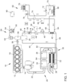
- Figure 1 shows an internal combustion engine 10 with at least one combustion chamber 12, which is intended to drive a motor vehicle.
- the internal combustion engine 10 is designed as a six-cylinder in-line engine. Alternatively, however, other embodiments, preferably with 2 - 12 cylinders, are also possible.
- the internal combustion engine 10 can alternatively be designed as a V-engine or boxer engine.
- the internal combustion engine 10 has a coolant circuit 18, via which the engine block of the internal combustion engine 10 is cooled in order to dissipate the waste heat of the internal combustion engine 10.
- the internal combustion engine 10 is connected with its outlet 14 to an exhaust system 20.
- the exhaust system 20 comprises an exhaust duct 22, in which a turbine of an exhaust gas turbocharger 16 and downstream of the turbine of the exhaust gas turbocharger 16 several exhaust gas aftertreatment components 24, 26 and a heat exchanger 32 of an exhaust gas heat recovery system 30 are arranged.
- the internal combustion engine 10 is designed as a self-igniting diesel engine and the exhaust gas aftertreatment components 24, 26 comprise an oxidation catalyst, a NOx storage catalyst, a particle filter and/or a catalyst for the selective catalytic reduction of nitrogen oxides.
- the exhaust system can also comprise a three-way catalyst or a four-way catalyst.
- an exhaust flap 28 Downstream of the heat exchanger 32, an exhaust flap 28 is provided, with which the exhaust duct 22 can be at least partially closed in order to increase the exhaust back pressure.
- the exhaust aftertreatment components 24, 26 and the heat exchanger 32 can also be arranged as an exhaust heat recovery assembly 84 in a common housing 82 in order to simplify the assembly of the exhaust system 20.
- the exhaust flap 28 can also be integrated into this exhaust heat recovery assembly 84.
- the exhaust heat recovery system 30 comprises, in addition to the heat exchanger 32, which also serves as an evaporator 32 for an operating fluid 39 of the exhaust heat recovery system 30, an expansion engine 34, a condenser 36, a pump 40 and a further heat exchanger 42, which serves to cool a compressed coolant 71 of an air conditioning circuit 60.
- the exhaust heat recovery system 30 further comprises a storage tank 38 for the operating fluid 39, in particular an organic working medium, preferably alcohol or an alcohol-water mixture, particularly preferably ethanol or an ethanol-water mixture.
- the storage tank 38 is connected to the pump 40 via a power line. in which the operating fluid 39 is compressed.
- the compressed operating medium is fed to the further heat exchanger 42, where it absorbs the waste heat of a pressurized coolant 71 and feeds it to the heat exchanger 32 via a feed line 48.
- the waste heat of the exhaust gas flow of the internal combustion engine 10 is transferred to the operating fluid and converts the operating fluid into the gaseous state.
- the steam generated in this process is fed via a steam line 44 to the expansion engine 34, which is operatively connected to a heabride module 50.
- the expansion engine 34 can be connected to a power distribution device 58 either via a mechanical drive shaft 56 to the internal combustion engine 10 or to a motor/generator 52 for generating electrical current.
- the motor/generator 52 is connected to an electrical system 54 of a motor vehicle and can temporarily store the electrical energy in a battery 55.
- a condenser 36 Downstream of the expansion engine 34, a condenser 36 is arranged in the exhaust heat recovery system 30, which has a coolant inlet 46 and a coolant return 47 and is connected to the cooling water circuit 18 of the internal combustion engine 10.
- the operating fluid of the exhaust heat recovery system 30 is converted back into the liquid state before it is fed back to the pump 40 via a return line 49.
- the internal combustion engine 10 can be coupled to an air conditioning compressor 62 of the air conditioning circuit 60 via a traction device, in particular a chain or a belt.
- the air conditioning circuit 60 comprises, in addition to the air conditioning compressor 62, the further heat exchanger 62, a coolant condenser 68, an expansion tank 70 and a coolant evaporator 76.
- the air conditioning compressor 62 is connected to the further heat exchanger 42 via a line 64, where the coolant 71 compressed by the air conditioning compressor 62 transfers its heat to the operating fluid 39 of the exhaust gas heat recovery system 30.
- the further heat exchanger 42 is connected to a coolant condenser 68 of the air conditioning circuit 60 via a further line 66.
- an expansion tank 70 Downstream of the coolant condenser 68, an expansion tank 70 is provided, in which the coolant 71 is stored.
- a high-pressure valve 72 is provided downstream of the expansion tank 70.
- the high-pressure valve 72 is connected via a line 74 to a refrigerant evaporator 76 in which the refrigerant 74 is expanded and evaporated, whereby energy is extracted from the refrigerant 71 so that the refrigerant 71 cools down considerably. This cold is used to air-condition the interior of a motor vehicle.
- the air conditioning circuit contains a Valve 78 and a damping volume 80 are provided to collect the relaxed refrigerant and feed it to the air conditioning compressor 62.
- the air conditioning compressor 62 compresses the coolant 71 to a pressure of at least 20 bar, preferably at least 100 bar, whereby the coolant 71, in particular carbon dioxide, heats up considerably. This heat is transferred via the further heat exchanger 42 to the operating fluid 39 of the exhaust gas heat recovery system 30, whereby the compressed coolant is simultaneously cooled.
- the combustion engine 10 is operatively connected to a control unit 90, via which the air conditioning circuit 60 and the exhaust gas heat recovery system 30 are controlled.
- FIG. 2 A pressure-enthalpy diagram is shown which illustrates the processes in the climate circuit 60.
- FIG. 3 a flow chart for carrying out a method according to the invention for exhaust gas heat recovery is shown.
- the air conditioning compressor 62 is operated and the coolant 71 is compressed.
- the compressed coolant 71 is fed to the further heat exchanger 42 in a method step ⁇ 110>.
- the compressed coolant 71 is cooled by the operating fluid 39 of the exhaust gas heat recovery system 30 and then fed to the coolant condenser 68.
- the coolant 71 is expanded and evaporates in the coolant evaporator 76 in a method step ⁇ 140>.
- the coolant 71 cools down and transfers this cold to an air flow that is fed to the interior of the motor vehicle.
- the expanded coolant is collected again and fed to the air conditioning compressor 62.
- the operating fluid 39 of the exhaust gas heat recovery system 30 is conveyed from the storage tank 38 into the further heat exchanger 42 in a process step ⁇ 200>. There, the hot, compressed coolant 71 transfers its heat to the colder operating fluid 39 in a process step ⁇ 210>, so that energy is supplied to the exhaust gas heat recovery system 30 and removed from the air conditioning circuit 60.
- the process steps ⁇ 120> and ⁇ 210> always run simultaneously.
- the heated operating fluid 39 is fed to the heat exchanger 32, where it is further heated by the exhaust gas flow and evaporates in a process step ⁇ 220>.
- the vaporous operating fluid 39 is fed to the expansion engine 34 via the steam line 44 and drives it in a process step ⁇ 230>.
- the operating fluid 39 is fed to the condenser 36 after flowing through the expansion engine 34, where it is cooled in a process step ⁇ 240> and converted back from the gaseous state to the liquid state.
- the cooled operating fluid is collected in a process step ⁇ 250> and fed back to the pump 40, thus closing the cycle of the exhaust gas heat recovery system.
- the efficiency of the internal combustion engine 10 can be increased, since the dissipated heat can be used and less energy has to be provided to drive the air conditioning compressor through the combustion of fuel.
Landscapes
- Engineering & Computer Science (AREA)
- Chemical & Material Sciences (AREA)
- Combustion & Propulsion (AREA)
- Mechanical Engineering (AREA)
- General Engineering & Computer Science (AREA)
- Engine Equipment That Uses Special Cycles (AREA)
Claims (13)
- Moteur à combustion interne (10) comportant au moins une chambre de combustion (12), le moteur à combustion interne (10) étant connecté par sa sortie (14) à un système d'échappement (20), un échangeur de chaleur (32) d'un système de récupération de chaleur d'échappement (30) étant disposé dans le système d'échappement (20), échangeur de chaleur à l'aide duquel la chaleur perdue du gaz d'échappement peut être transmise à un fluide de fonctionnement (39) du système de récupération de chaleur d'échappement (30), le système de récupération de chaleur d'échappement (30) présentant un autre échangeur de chaleur (42) dans lequel la chaleur perdue d'un réfrigérant comprimé (71) d'un circuit de climatisation (60) peut être transmise au fluide de fonctionnement (39) du système de récupération de chaleur d'échappement (30), et une machine motrice à expansion (34) étant disposée dans un circuit de fluide de fonctionnement du système de récupération de chaleur d'échappement (30), machine par le biais de laquelle un moteur (10) et/ou un générateur (52) peu(ven)t être entraîné(s), caractérisé en ce que la machine motrice à expansion (34) peut être accouplée par le biais d'un dispositif de répartition de puissance (58) sélectivement au moteur à combustion interne (10) et/ou à un moteur d'entraînement électrique (52) ou à un générateur (52).
- Moteur à combustion interne (10) selon la revendication 1, caractérisé en ce que l'autre échangeur de chaleur (42) est disposé dans un circuit de fluide de fonctionnement du système de récupération de chaleur d'échappement (30) en aval d'une pompe (40) pour le fluide de fonctionnement (39) et en amont de l'échangeur de chaleur (32) traversé par le gaz d'échappement du moteur à combustion interne (10).
- Moteur à combustion interne (10) selon la revendication 1 ou 2, caractérisé en ce qu'un condenseur (36) est disposé dans le circuit de fluide de fonctionnement du système de récupération de chaleur d'échappement (30) en aval de la machine motrice à expansion (34) et en amont d'une pompe (40) pour le fluide de fonctionnement (39).
- Moteur à combustion interne (10) selon la revendication 3, caractérisé en ce que le condenseur (36) présente une amenée de réfrigérant (46) et un retour de réfrigérant (47), lesquels sont connectés à un circuit d'eau de refroidissement (18) du moteur à combustion interne (10).
- Moteur à combustion interne (10) selon la revendication 3 ou 4, caractérisé en ce qu'un réservoir de stockage (38) pour le fluide de fonctionnement (39) est disposé en aval du condenseur (36) et en amont de la pompe (40).
- Moteur à combustion interne (10) selon l'une des revendications 1 à 5, caractérisé en ce que le fluide de fonctionnement (39) du système de récupération de chaleur d'échappement (30) est un alcool, en particulier de l'éthanol.
- Moteur à combustion interne (10) selon l'une des revendications 1 à 6, caractérisé en ce que le circuit de climatisation (60) présente un compresseur de climatisation (62) et un condenseur de réfrigérant (68), l'autre échangeur de chaleur (42) étant traversé par le réfrigérant (71) comprimé par le compresseur de climatisation (62), avant que le réfrigérant comprimé (71) n'entre dans le condenseur de réfrigérant (68).
- Moteur à combustion interne (10) selon l'une des revendications 1 à 7, caractérisé en ce que le circuit de climatisation (60) présente un réservoir d'expansion (70) en aval du condenseur de réfrigérant (68) et en amont d'un évaporateur de réfrigérant (76).
- Moteur à combustion interne (10) selon l'une des revendications 1 à 8, caractérisé en ce que le réfrigérant (71) du circuit de climatisation (60) est du dioxyde de carbone.
- Procédé de récupération de chaleur d'échappement d'un moteur à combustion interne (10) selon l'une des revendications 1 à 9, caractérisé en ce qu'un fluide de fonctionnement (39) du système de récupération de chaleur d'échappement (30) est réchauffé, dans une première étape de procédé, par la chaleur perdue d'un réfrigérant comprimé (71) du circuit de climatisation (60) et, dans une deuxième étape de procédé, par la chaleur perdue du gaz d'échappement du moteur à combustion interne (10).
- Procédé de récupération de chaleur d'échappement d'un moteur à combustion interne (10) selon la revendication 10, caractérisé en ce que le réfrigérant (71) est comprimé à une pression de fonctionnement d'au moins 20 bars, de préférence d'au moins 100 bars.
- Procédé de récupération de chaleur d'échappement d'un moteur à combustion interne (10) selon la revendication 10 ou 11, caractérisé en ce que la chaleur perdue du réfrigérant comprimé (71) est transmise au fluide de fonctionnement du système de récupération de chaleur d'échappement (10) en aval d'une pompe (40).
- Procédé de récupération de chaleur d'échappement d'un moteur à combustion interne (10) selon l'une des revendications 10 à 12, caractérisé en ce qu'un compresseur de climatisation (62) du circuit de climatisation (60) est entraîné par un arbre rotatif du moteur à combustion interne (10) au moyen d'un lien souple, en particulier d'une chaîne ou d'une courroie.
Applications Claiming Priority (1)
| Application Number | Priority Date | Filing Date | Title |
|---|---|---|---|
| DE102019115909.1A DE102019115909A1 (de) | 2019-06-12 | 2019-06-12 | Verbrennungsmotor mit Abgaswärmerückgewinnungssystem sowie Verfahren zur Abgaswärmerückgewinnung |
Publications (2)
| Publication Number | Publication Date |
|---|---|
| EP3751107A1 EP3751107A1 (fr) | 2020-12-16 |
| EP3751107B1 true EP3751107B1 (fr) | 2024-04-10 |
Family
ID=71119911
Family Applications (1)
| Application Number | Title | Priority Date | Filing Date |
|---|---|---|---|
| EP20179402.1A Active EP3751107B1 (fr) | 2019-06-12 | 2020-06-11 | Moteur a combustion interne ayant un système de récupération de chaleur d'échappement et procédé pour la récupération de chaleur d'échappement |
Country Status (3)
| Country | Link |
|---|---|
| US (1) | US11035270B2 (fr) |
| EP (1) | EP3751107B1 (fr) |
| DE (1) | DE102019115909A1 (fr) |
Families Citing this family (4)
| Publication number | Priority date | Publication date | Assignee | Title |
|---|---|---|---|---|
| DE102021114792B4 (de) * | 2021-06-09 | 2023-02-02 | Audi Aktiengesellschaft | Elektrofahrzeug mit Energierückgewinnungssystem |
| US12116908B2 (en) * | 2022-08-17 | 2024-10-15 | Innio Waukesha Gas Engines Inc. | System for utilizing a thermomechanical cycle to drive a compressor |
| DE102024200256B4 (de) * | 2024-01-12 | 2025-12-04 | Zf Friedrichshafen Ag | Thermomanagement-System für ein Fahrzeug und Fahrzeug mit einem solchen System |
| EP4650582A1 (fr) * | 2024-05-17 | 2025-11-19 | BorgWarner, Inc. | Système de refroidissement pour refroidir un composant d'automobile |
Citations (1)
| Publication number | Priority date | Publication date | Assignee | Title |
|---|---|---|---|---|
| US20150000274A1 (en) * | 2013-06-28 | 2015-01-01 | Cummins Inc. | Waste heat recovery system including connection to a vehicle air conditioning system |
Family Cites Families (21)
| Publication number | Priority date | Publication date | Assignee | Title |
|---|---|---|---|---|
| US5351487A (en) * | 1992-05-26 | 1994-10-04 | Abdelmalek Fawzy T | High efficiency natural gas engine driven cooling system |
| DE60113646T2 (de) * | 2000-01-21 | 2006-03-16 | Honda Giken Kogyo K.K. | Abgasreinigungsvorrichtung und brennkraftmaschine |
| JP4140544B2 (ja) * | 2004-03-26 | 2008-08-27 | 株式会社デンソー | 廃熱利用装置 |
| DE102005024685A1 (de) | 2004-05-31 | 2005-12-29 | Denso Corp., Kariya | Wärmekreis |
| EP1902198A2 (fr) * | 2005-06-16 | 2008-03-26 | UTC Power Corporation | Cycle organique de rankine couple mecaniquement et thermiquement a un moteur entrainant une charge commune |
| JP2009167994A (ja) * | 2008-01-21 | 2009-07-30 | Sanden Corp | 内燃機関の廃熱利用装置 |
| US8393171B2 (en) * | 2010-04-13 | 2013-03-12 | Gerald Allen Alston | Mechanically enhanced ejector HVAC and electric power generation system |
| DE102010023174A1 (de) | 2010-06-09 | 2011-12-15 | Georg Beckmann | Verfahren und Einrichtung zur Nutzung der Abwärmen von Verbrennungskraftmaschinen mittels eines Dampfkreislaufes |
| DE102012000100A1 (de) * | 2011-01-06 | 2012-07-12 | Cummins Intellectual Property, Inc. | Rankine-kreisprozess-abwärmenutzungssystem |
| SE535680C2 (sv) | 2011-03-17 | 2012-11-06 | Scania Cv Ab | Arrangemang för att omvandla värmeenergi till mekanisk energi i ett fordon |
| JP5804879B2 (ja) * | 2011-09-30 | 2015-11-04 | 日産自動車株式会社 | 廃熱利用装置 |
| CH708685A2 (de) * | 2013-10-14 | 2015-04-15 | Weidmann Plastics Tech Ag | Kraftfahrzeug mit einer Klimaanlage. |
| JP6387245B2 (ja) * | 2014-05-15 | 2018-09-05 | 日産自動車株式会社 | エンジンの廃熱利用装置 |
| JP6410851B2 (ja) | 2014-06-26 | 2018-10-24 | ボルボトラックコーポレーション | 廃熱回収装置 |
| US10801372B2 (en) | 2014-10-31 | 2020-10-13 | Modine Manufacturing Company | Cooling module and method for rejecting heat from a coupled engine system and rankine cycle waste heat recovery system |
| DE102014016997A1 (de) | 2014-11-18 | 2016-05-19 | Klaus-Peter Priebe | Mehrstufiges Verfahren zur Nutzung von zwei und mehr Wärmequellen zum Betrieb einer ein- oder mehrstufigen Arbeitsmaschine, Vorwärmung RL-Motorkühlung |
| SE538835C2 (en) | 2014-12-05 | 2016-12-20 | Scania Cv Ab | A cooling arrangement for a WHR system |
| FR3030702B1 (fr) * | 2014-12-17 | 2019-09-13 | Valeo Systemes Thermiques | Circuit de gestion thermique d'un vehicule automobile et procede de pilotage associe |
| WO2017105480A1 (fr) * | 2015-12-18 | 2017-06-22 | Cummins Inc. | Système de refroidissement intégré pour moteur et récupération de chaleur perdue |
| SE539690C2 (en) * | 2016-02-04 | 2017-10-31 | Scania Cv Ab | A method for controlling a waste heat recovery system and such a waste heat recovery system |
| US11607928B2 (en) * | 2017-03-10 | 2023-03-21 | Mobile Climate Control, Corp. | Method and apparatus for cooling an air conditioning system controller |
-
2019
- 2019-06-12 DE DE102019115909.1A patent/DE102019115909A1/de not_active Withdrawn
-
2020
- 2020-06-11 US US16/899,563 patent/US11035270B2/en not_active Expired - Fee Related
- 2020-06-11 EP EP20179402.1A patent/EP3751107B1/fr active Active
Patent Citations (1)
| Publication number | Priority date | Publication date | Assignee | Title |
|---|---|---|---|---|
| US20150000274A1 (en) * | 2013-06-28 | 2015-01-01 | Cummins Inc. | Waste heat recovery system including connection to a vehicle air conditioning system |
Also Published As
| Publication number | Publication date |
|---|---|
| DE102019115909A1 (de) | 2020-12-17 |
| US20200392883A1 (en) | 2020-12-17 |
| US11035270B2 (en) | 2021-06-15 |
| EP3751107A1 (fr) | 2020-12-16 |
Similar Documents
| Publication | Publication Date | Title |
|---|---|---|
| EP3751107B1 (fr) | Moteur a combustion interne ayant un système de récupération de chaleur d'échappement et procédé pour la récupération de chaleur d'échappement | |
| EP1549827B1 (fr) | Procede et dispositif de recuperation d'energie | |
| DE102011012584B4 (de) | Fahrzeug-Abwärmerückgewinnungssystem | |
| EP1830046B1 (fr) | Unité d'entraînement dotée d'un gain de retour de chaleur | |
| DE102005049831B4 (de) | Dampfkompressionskühlvorrichtung | |
| EP2686526B1 (fr) | Procédé pour faire fonctionner un processus à circuit de vapeur | |
| DE102006043139B4 (de) | Vorrichtung zur Gewinnung von mechanischer oder elektrischer Energie aus der Abwärme eines Verbrennungsmotors eines Kraftfahrzeugs | |
| EP2196661A2 (fr) | Unité d'entraînement dotée d'un circuit de refroidissement et d'un circuit de récupération de chaleur séparé | |
| DE102010042405A1 (de) | Vorrichtung und Verfahren zur Abwärmenutzung einer Brennkraftmaschine | |
| WO2008034540A1 (fr) | Systéme d'échangeur de chaleur | |
| DE102010049916A1 (de) | Verfahren und Vorrichtung zur Abwärmenutzung aus einem Abgasstrom einer Verbrennungskraftmaschine | |
| DE102010003906A1 (de) | Verbrennungsmotor | |
| WO2012055555A2 (fr) | Moteur à combustion interne | |
| EP2020316A1 (fr) | Mémoire destinée au refroidissement d'un fluide essentiellement gazeux prévu pour le chargement du moteur | |
| DE102014019097A1 (de) | Vorrichtung zur Ladeluftkühlung und Fahrzeug mit einer solchen Vorrichtung | |
| DE102013011521A1 (de) | Antriebseinheit für ein Kraftfahrzeug | |
| DE102010025186A1 (de) | Abwärmenutzungsvorrichtung, Brennkraftmaschine und Kraftfahrzeug | |
| DE102016218764A1 (de) | Brennkraftmaschine eines Kraftfahrzeugs mit einer Abwärmenutzungseinrichtung | |
| DE102012222082A1 (de) | Vorrichtung und Verfahren zur Abwärmenutzung einer Brennkraftmaschine | |
| DE202017100590U1 (de) | System zur Wärmerückgewinnung und Ladeluftverdichtung | |
| DE102008053066A1 (de) | System mit einem Rankine-Kreislauf | |
| DE102018004554A1 (de) | Temperiereinrichtung für ein Hybridfahrzeug | |
| DE102017011851A1 (de) | Anordnung zur Umwandlung thermischer Energie aus Verlustwärme einer Verbrennungskraftmaschine | |
| DE102011109384A1 (de) | Brennkraftmaschine mit einer Wärmerückgewinnungsvorrichtung und Verfahren zum Betrieb einer Brennkraftmaschine | |
| EP2733339B1 (fr) | Dispositif d'utilisation de la chaleur rejetée d'un moteur à combustion interne |
Legal Events
| Date | Code | Title | Description |
|---|---|---|---|
| PUAI | Public reference made under article 153(3) epc to a published international application that has entered the european phase |
Free format text: ORIGINAL CODE: 0009012 |
|
| STAA | Information on the status of an ep patent application or granted ep patent |
Free format text: STATUS: THE APPLICATION HAS BEEN PUBLISHED |
|
| AK | Designated contracting states |
Kind code of ref document: A1 Designated state(s): AL AT BE BG CH CY CZ DE DK EE ES FI FR GB GR HR HU IE IS IT LI LT LU LV MC MK MT NL NO PL PT RO RS SE SI SK SM TR |
|
| AX | Request for extension of the european patent |
Extension state: BA ME |
|
| STAA | Information on the status of an ep patent application or granted ep patent |
Free format text: STATUS: REQUEST FOR EXAMINATION WAS MADE |
|
| 17P | Request for examination filed |
Effective date: 20210616 |
|
| RBV | Designated contracting states (corrected) |
Designated state(s): AL AT BE BG CH CY CZ DE DK EE ES FI FR GB GR HR HU IE IS IT LI LT LU LV MC MK MT NL NO PL PT RO RS SE SI SK SM TR |
|
| STAA | Information on the status of an ep patent application or granted ep patent |
Free format text: STATUS: EXAMINATION IS IN PROGRESS |
|
| 17Q | First examination report despatched |
Effective date: 20220103 |
|
| GRAP | Despatch of communication of intention to grant a patent |
Free format text: ORIGINAL CODE: EPIDOSNIGR1 |
|
| STAA | Information on the status of an ep patent application or granted ep patent |
Free format text: STATUS: GRANT OF PATENT IS INTENDED |
|
| INTG | Intention to grant announced |
Effective date: 20231108 |
|
| GRAS | Grant fee paid |
Free format text: ORIGINAL CODE: EPIDOSNIGR3 |
|
| GRAA | (expected) grant |
Free format text: ORIGINAL CODE: 0009210 |
|
| STAA | Information on the status of an ep patent application or granted ep patent |
Free format text: STATUS: THE PATENT HAS BEEN GRANTED |
|
| AK | Designated contracting states |
Kind code of ref document: B1 Designated state(s): AL AT BE BG CH CY CZ DE DK EE ES FI FR GB GR HR HU IE IS IT LI LT LU LV MC MK MT NL NO PL PT RO RS SE SI SK SM TR |
|
| REG | Reference to a national code |
Ref country code: GB Ref legal event code: FG4D Free format text: NOT ENGLISH |
|
| REG | Reference to a national code |
Ref country code: CH Ref legal event code: EP |
|
| REG | Reference to a national code |
Ref country code: DE Ref legal event code: R096 Ref document number: 502020007597 Country of ref document: DE |
|
| P01 | Opt-out of the competence of the unified patent court (upc) registered |
Effective date: 20240327 |
|
| REG | Reference to a national code |
Ref country code: IE Ref legal event code: FG4D Free format text: LANGUAGE OF EP DOCUMENT: GERMAN |
|
| REG | Reference to a national code |
Ref country code: LT Ref legal event code: MG9D |
|
| REG | Reference to a national code |
Ref country code: NL Ref legal event code: MP Effective date: 20240410 |
|
| PG25 | Lapsed in a contracting state [announced via postgrant information from national office to epo] |
Ref country code: NL Free format text: LAPSE BECAUSE OF FAILURE TO SUBMIT A TRANSLATION OF THE DESCRIPTION OR TO PAY THE FEE WITHIN THE PRESCRIBED TIME-LIMIT Effective date: 20240410 |
|
| PG25 | Lapsed in a contracting state [announced via postgrant information from national office to epo] |
Ref country code: NL Free format text: LAPSE BECAUSE OF FAILURE TO SUBMIT A TRANSLATION OF THE DESCRIPTION OR TO PAY THE FEE WITHIN THE PRESCRIBED TIME-LIMIT Effective date: 20240410 |
|
| PG25 | Lapsed in a contracting state [announced via postgrant information from national office to epo] |
Ref country code: IS Free format text: LAPSE BECAUSE OF FAILURE TO SUBMIT A TRANSLATION OF THE DESCRIPTION OR TO PAY THE FEE WITHIN THE PRESCRIBED TIME-LIMIT Effective date: 20240810 |
|
| PG25 | Lapsed in a contracting state [announced via postgrant information from national office to epo] |
Ref country code: BG Free format text: LAPSE BECAUSE OF FAILURE TO SUBMIT A TRANSLATION OF THE DESCRIPTION OR TO PAY THE FEE WITHIN THE PRESCRIBED TIME-LIMIT Effective date: 20240410 |
|
| PG25 | Lapsed in a contracting state [announced via postgrant information from national office to epo] |
Ref country code: HR Free format text: LAPSE BECAUSE OF FAILURE TO SUBMIT A TRANSLATION OF THE DESCRIPTION OR TO PAY THE FEE WITHIN THE PRESCRIBED TIME-LIMIT Effective date: 20240410 Ref country code: FI Free format text: LAPSE BECAUSE OF FAILURE TO SUBMIT A TRANSLATION OF THE DESCRIPTION OR TO PAY THE FEE WITHIN THE PRESCRIBED TIME-LIMIT Effective date: 20240410 |
|
| PG25 | Lapsed in a contracting state [announced via postgrant information from national office to epo] |
Ref country code: GR Free format text: LAPSE BECAUSE OF FAILURE TO SUBMIT A TRANSLATION OF THE DESCRIPTION OR TO PAY THE FEE WITHIN THE PRESCRIBED TIME-LIMIT Effective date: 20240711 |
|
| PG25 | Lapsed in a contracting state [announced via postgrant information from national office to epo] |
Ref country code: PT Free format text: LAPSE BECAUSE OF FAILURE TO SUBMIT A TRANSLATION OF THE DESCRIPTION OR TO PAY THE FEE WITHIN THE PRESCRIBED TIME-LIMIT Effective date: 20240812 |
|
| PG25 | Lapsed in a contracting state [announced via postgrant information from national office to epo] |
Ref country code: ES Free format text: LAPSE BECAUSE OF FAILURE TO SUBMIT A TRANSLATION OF THE DESCRIPTION OR TO PAY THE FEE WITHIN THE PRESCRIBED TIME-LIMIT Effective date: 20240410 |
|
| PG25 | Lapsed in a contracting state [announced via postgrant information from national office to epo] |
Ref country code: PL Free format text: LAPSE BECAUSE OF FAILURE TO SUBMIT A TRANSLATION OF THE DESCRIPTION OR TO PAY THE FEE WITHIN THE PRESCRIBED TIME-LIMIT Effective date: 20240410 |
|
| PG25 | Lapsed in a contracting state [announced via postgrant information from national office to epo] |
Ref country code: LV Free format text: LAPSE BECAUSE OF FAILURE TO SUBMIT A TRANSLATION OF THE DESCRIPTION OR TO PAY THE FEE WITHIN THE PRESCRIBED TIME-LIMIT Effective date: 20240410 |
|
| PG25 | Lapsed in a contracting state [announced via postgrant information from national office to epo] |
Ref country code: PT Free format text: LAPSE BECAUSE OF FAILURE TO SUBMIT A TRANSLATION OF THE DESCRIPTION OR TO PAY THE FEE WITHIN THE PRESCRIBED TIME-LIMIT Effective date: 20240812 Ref country code: PL Free format text: LAPSE BECAUSE OF FAILURE TO SUBMIT A TRANSLATION OF THE DESCRIPTION OR TO PAY THE FEE WITHIN THE PRESCRIBED TIME-LIMIT Effective date: 20240410 Ref country code: NO Free format text: LAPSE BECAUSE OF FAILURE TO SUBMIT A TRANSLATION OF THE DESCRIPTION OR TO PAY THE FEE WITHIN THE PRESCRIBED TIME-LIMIT Effective date: 20240710 Ref country code: LV Free format text: LAPSE BECAUSE OF FAILURE TO SUBMIT A TRANSLATION OF THE DESCRIPTION OR TO PAY THE FEE WITHIN THE PRESCRIBED TIME-LIMIT Effective date: 20240410 Ref country code: IS Free format text: LAPSE BECAUSE OF FAILURE TO SUBMIT A TRANSLATION OF THE DESCRIPTION OR TO PAY THE FEE WITHIN THE PRESCRIBED TIME-LIMIT Effective date: 20240810 Ref country code: HR Free format text: LAPSE BECAUSE OF FAILURE TO SUBMIT A TRANSLATION OF THE DESCRIPTION OR TO PAY THE FEE WITHIN THE PRESCRIBED TIME-LIMIT Effective date: 20240410 Ref country code: GR Free format text: LAPSE BECAUSE OF FAILURE TO SUBMIT A TRANSLATION OF THE DESCRIPTION OR TO PAY THE FEE WITHIN THE PRESCRIBED TIME-LIMIT Effective date: 20240711 Ref country code: FI Free format text: LAPSE BECAUSE OF FAILURE TO SUBMIT A TRANSLATION OF THE DESCRIPTION OR TO PAY THE FEE WITHIN THE PRESCRIBED TIME-LIMIT Effective date: 20240410 Ref country code: ES Free format text: LAPSE BECAUSE OF FAILURE TO SUBMIT A TRANSLATION OF THE DESCRIPTION OR TO PAY THE FEE WITHIN THE PRESCRIBED TIME-LIMIT Effective date: 20240410 Ref country code: BG Free format text: LAPSE BECAUSE OF FAILURE TO SUBMIT A TRANSLATION OF THE DESCRIPTION OR TO PAY THE FEE WITHIN THE PRESCRIBED TIME-LIMIT Effective date: 20240410 Ref country code: RS Free format text: LAPSE BECAUSE OF FAILURE TO SUBMIT A TRANSLATION OF THE DESCRIPTION OR TO PAY THE FEE WITHIN THE PRESCRIBED TIME-LIMIT Effective date: 20240710 |
|
| REG | Reference to a national code |
Ref country code: DE Ref legal event code: R097 Ref document number: 502020007597 Country of ref document: DE |
|
| PG25 | Lapsed in a contracting state [announced via postgrant information from national office to epo] |
Ref country code: DK Free format text: LAPSE BECAUSE OF FAILURE TO SUBMIT A TRANSLATION OF THE DESCRIPTION OR TO PAY THE FEE WITHIN THE PRESCRIBED TIME-LIMIT Effective date: 20240410 |
|
| PG25 | Lapsed in a contracting state [announced via postgrant information from national office to epo] |
Ref country code: EE Free format text: LAPSE BECAUSE OF FAILURE TO SUBMIT A TRANSLATION OF THE DESCRIPTION OR TO PAY THE FEE WITHIN THE PRESCRIBED TIME-LIMIT Effective date: 20240410 |
|
| PG25 | Lapsed in a contracting state [announced via postgrant information from national office to epo] |
Ref country code: CZ Free format text: LAPSE BECAUSE OF FAILURE TO SUBMIT A TRANSLATION OF THE DESCRIPTION OR TO PAY THE FEE WITHIN THE PRESCRIBED TIME-LIMIT Effective date: 20240410 |
|
| PG25 | Lapsed in a contracting state [announced via postgrant information from national office to epo] |
Ref country code: SK Free format text: LAPSE BECAUSE OF FAILURE TO SUBMIT A TRANSLATION OF THE DESCRIPTION OR TO PAY THE FEE WITHIN THE PRESCRIBED TIME-LIMIT Effective date: 20240410 Ref country code: RO Free format text: LAPSE BECAUSE OF FAILURE TO SUBMIT A TRANSLATION OF THE DESCRIPTION OR TO PAY THE FEE WITHIN THE PRESCRIBED TIME-LIMIT Effective date: 20240410 |
|
| PG25 | Lapsed in a contracting state [announced via postgrant information from national office to epo] |
Ref country code: SM Free format text: LAPSE BECAUSE OF FAILURE TO SUBMIT A TRANSLATION OF THE DESCRIPTION OR TO PAY THE FEE WITHIN THE PRESCRIBED TIME-LIMIT Effective date: 20240410 |
|
| PG25 | Lapsed in a contracting state [announced via postgrant information from national office to epo] |
Ref country code: SM Free format text: LAPSE BECAUSE OF FAILURE TO SUBMIT A TRANSLATION OF THE DESCRIPTION OR TO PAY THE FEE WITHIN THE PRESCRIBED TIME-LIMIT Effective date: 20240410 Ref country code: SK Free format text: LAPSE BECAUSE OF FAILURE TO SUBMIT A TRANSLATION OF THE DESCRIPTION OR TO PAY THE FEE WITHIN THE PRESCRIBED TIME-LIMIT Effective date: 20240410 Ref country code: RO Free format text: LAPSE BECAUSE OF FAILURE TO SUBMIT A TRANSLATION OF THE DESCRIPTION OR TO PAY THE FEE WITHIN THE PRESCRIBED TIME-LIMIT Effective date: 20240410 Ref country code: EE Free format text: LAPSE BECAUSE OF FAILURE TO SUBMIT A TRANSLATION OF THE DESCRIPTION OR TO PAY THE FEE WITHIN THE PRESCRIBED TIME-LIMIT Effective date: 20240410 Ref country code: DK Free format text: LAPSE BECAUSE OF FAILURE TO SUBMIT A TRANSLATION OF THE DESCRIPTION OR TO PAY THE FEE WITHIN THE PRESCRIBED TIME-LIMIT Effective date: 20240410 Ref country code: CZ Free format text: LAPSE BECAUSE OF FAILURE TO SUBMIT A TRANSLATION OF THE DESCRIPTION OR TO PAY THE FEE WITHIN THE PRESCRIBED TIME-LIMIT Effective date: 20240410 Ref country code: MC Free format text: LAPSE BECAUSE OF FAILURE TO SUBMIT A TRANSLATION OF THE DESCRIPTION OR TO PAY THE FEE WITHIN THE PRESCRIBED TIME-LIMIT Effective date: 20240410 |
|
| REG | Reference to a national code |
Ref country code: CH Ref legal event code: PL |
|
| PG25 | Lapsed in a contracting state [announced via postgrant information from national office to epo] |
Ref country code: IT Free format text: LAPSE BECAUSE OF FAILURE TO SUBMIT A TRANSLATION OF THE DESCRIPTION OR TO PAY THE FEE WITHIN THE PRESCRIBED TIME-LIMIT Effective date: 20240410 |
|
| PLBE | No opposition filed within time limit |
Free format text: ORIGINAL CODE: 0009261 |
|
| STAA | Information on the status of an ep patent application or granted ep patent |
Free format text: STATUS: NO OPPOSITION FILED WITHIN TIME LIMIT |
|
| PG25 | Lapsed in a contracting state [announced via postgrant information from national office to epo] |
Ref country code: LU Free format text: LAPSE BECAUSE OF NON-PAYMENT OF DUE FEES Effective date: 20240611 |
|
| REG | Reference to a national code |
Ref country code: DE Ref legal event code: R082 Ref document number: 502020007597 Country of ref document: DE |
|
| 26N | No opposition filed |
Effective date: 20250113 |
|
| GBPC | Gb: european patent ceased through non-payment of renewal fee |
Effective date: 20240710 |
|
| PG25 | Lapsed in a contracting state [announced via postgrant information from national office to epo] |
Ref country code: IE Free format text: LAPSE BECAUSE OF NON-PAYMENT OF DUE FEES Effective date: 20240611 |
|
| PG25 | Lapsed in a contracting state [announced via postgrant information from national office to epo] |
Ref country code: SI Free format text: LAPSE BECAUSE OF FAILURE TO SUBMIT A TRANSLATION OF THE DESCRIPTION OR TO PAY THE FEE WITHIN THE PRESCRIBED TIME-LIMIT Effective date: 20240410 Ref country code: CH Free format text: LAPSE BECAUSE OF NON-PAYMENT OF DUE FEES Effective date: 20240630 Ref country code: BE Free format text: LAPSE BECAUSE OF NON-PAYMENT OF DUE FEES Effective date: 20240630 |
|
| PG25 | Lapsed in a contracting state [announced via postgrant information from national office to epo] |
Ref country code: GB Free format text: LAPSE BECAUSE OF NON-PAYMENT OF DUE FEES Effective date: 20240710 |
|
| REG | Reference to a national code |
Ref country code: BE Ref legal event code: MM Effective date: 20240630 |
|
| PGFP | Annual fee paid to national office [announced via postgrant information from national office to epo] |
Ref country code: DE Payment date: 20250630 Year of fee payment: 6 |
|
| PGFP | Annual fee paid to national office [announced via postgrant information from national office to epo] |
Ref country code: FR Payment date: 20250624 Year of fee payment: 6 |
|
| PGFP | Annual fee paid to national office [announced via postgrant information from national office to epo] |
Ref country code: AT Payment date: 20250721 Year of fee payment: 5 |
|
| PG25 | Lapsed in a contracting state [announced via postgrant information from national office to epo] |
Ref country code: SE Free format text: LAPSE BECAUSE OF FAILURE TO SUBMIT A TRANSLATION OF THE DESCRIPTION OR TO PAY THE FEE WITHIN THE PRESCRIBED TIME-LIMIT Effective date: 20240410 |
|
| PG25 | Lapsed in a contracting state [announced via postgrant information from national office to epo] |
Ref country code: CY Free format text: LAPSE BECAUSE OF FAILURE TO SUBMIT A TRANSLATION OF THE DESCRIPTION OR TO PAY THE FEE WITHIN THE PRESCRIBED TIME-LIMIT; INVALID AB INITIO Effective date: 20200611 |
|
| PG25 | Lapsed in a contracting state [announced via postgrant information from national office to epo] |
Ref country code: HU Free format text: LAPSE BECAUSE OF FAILURE TO SUBMIT A TRANSLATION OF THE DESCRIPTION OR TO PAY THE FEE WITHIN THE PRESCRIBED TIME-LIMIT; INVALID AB INITIO Effective date: 20200611 |