EP3751255B1 - Détection de gaz par mesure différentielle de la longueur du trajet - Google Patents
Détection de gaz par mesure différentielle de la longueur du trajet Download PDFInfo
- Publication number
- EP3751255B1 EP3751255B1 EP20179106.8A EP20179106A EP3751255B1 EP 3751255 B1 EP3751255 B1 EP 3751255B1 EP 20179106 A EP20179106 A EP 20179106A EP 3751255 B1 EP3751255 B1 EP 3751255B1
- Authority
- EP
- European Patent Office
- Prior art keywords
- light
- gas
- optical
- path length
- detector
- Prior art date
- Legal status (The legal status is an assumption and is not a legal conclusion. Google has not performed a legal analysis and makes no representation as to the accuracy of the status listed.)
- Active
Links
Images


Classifications
-
- G—PHYSICS
- G01—MEASURING; TESTING
- G01N—INVESTIGATING OR ANALYSING MATERIALS BY DETERMINING THEIR CHEMICAL OR PHYSICAL PROPERTIES
- G01N21/00—Investigating or analysing materials by the use of optical means, i.e. using sub-millimetre waves, infrared, visible or ultraviolet light
- G01N21/17—Systems in which incident light is modified in accordance with the properties of the material investigated
- G01N21/25—Colour; Spectral properties, i.e. comparison of effect of material on the light at two or more different wavelengths or wavelength bands
- G01N21/31—Investigating relative effect of material at wavelengths characteristic of specific elements or molecules, e.g. atomic absorption spectrometry
- G01N21/35—Investigating relative effect of material at wavelengths characteristic of specific elements or molecules, e.g. atomic absorption spectrometry using infrared light
- G01N21/3504—Investigating relative effect of material at wavelengths characteristic of specific elements or molecules, e.g. atomic absorption spectrometry using infrared light for analysing gases, e.g. multi-gas analysis
-
- G—PHYSICS
- G01—MEASURING; TESTING
- G01J—MEASUREMENT OF INTENSITY, VELOCITY, SPECTRAL CONTENT, POLARISATION, PHASE OR PULSE CHARACTERISTICS OF INFRARED, VISIBLE OR ULTRAVIOLET LIGHT; COLORIMETRY; RADIATION PYROMETRY
- G01J3/00—Spectrometry; Spectrophotometry; Monochromators; Measuring colours
- G01J3/02—Details
- G01J3/0205—Optical elements not provided otherwise, e.g. optical manifolds, diffusers, windows
- G01J3/0208—Optical elements not provided otherwise, e.g. optical manifolds, diffusers, windows using focussing or collimating elements, e.g. lenses or mirrors; performing aberration correction
-
- G—PHYSICS
- G01—MEASURING; TESTING
- G01J—MEASUREMENT OF INTENSITY, VELOCITY, SPECTRAL CONTENT, POLARISATION, PHASE OR PULSE CHARACTERISTICS OF INFRARED, VISIBLE OR ULTRAVIOLET LIGHT; COLORIMETRY; RADIATION PYROMETRY
- G01J3/00—Spectrometry; Spectrophotometry; Monochromators; Measuring colours
- G01J3/28—Investigating the spectrum
- G01J3/42—Absorption spectrometry; Double beam spectrometry; Flicker spectrometry; Reflection spectrometry
-
- G—PHYSICS
- G01—MEASURING; TESTING
- G01N—INVESTIGATING OR ANALYSING MATERIALS BY DETERMINING THEIR CHEMICAL OR PHYSICAL PROPERTIES
- G01N21/00—Investigating or analysing materials by the use of optical means, i.e. using sub-millimetre waves, infrared, visible or ultraviolet light
- G01N21/17—Systems in which incident light is modified in accordance with the properties of the material investigated
- G01N21/25—Colour; Spectral properties, i.e. comparison of effect of material on the light at two or more different wavelengths or wavelength bands
- G01N21/31—Investigating relative effect of material at wavelengths characteristic of specific elements or molecules, e.g. atomic absorption spectrometry
- G01N21/314—Investigating relative effect of material at wavelengths characteristic of specific elements or molecules, e.g. atomic absorption spectrometry with comparison of measurements at specific and non-specific wavelengths
- G01N21/3151—Investigating relative effect of material at wavelengths characteristic of specific elements or molecules, e.g. atomic absorption spectrometry with comparison of measurements at specific and non-specific wavelengths using two sources of radiation of different wavelengths
-
- G—PHYSICS
- G01—MEASURING; TESTING
- G01N—INVESTIGATING OR ANALYSING MATERIALS BY DETERMINING THEIR CHEMICAL OR PHYSICAL PROPERTIES
- G01N33/00—Investigating or analysing materials by specific methods not covered by groups G01N1/00 - G01N31/00
- G01N33/0004—Gaseous mixtures, e.g. polluted air
- G01N33/0009—General constructional details of gas analysers, e.g. portable test equipment
- G01N33/0022—General constructional details of gas analysers, e.g. portable test equipment using a number of analysing channels
-
- G—PHYSICS
- G01—MEASURING; TESTING
- G01N—INVESTIGATING OR ANALYSING MATERIALS BY DETERMINING THEIR CHEMICAL OR PHYSICAL PROPERTIES
- G01N33/00—Investigating or analysing materials by specific methods not covered by groups G01N1/00 - G01N31/00
- G01N33/0004—Gaseous mixtures, e.g. polluted air
- G01N33/0009—General constructional details of gas analysers, e.g. portable test equipment
- G01N33/0027—General constructional details of gas analysers, e.g. portable test equipment concerning the detector
- G01N33/0036—General constructional details of gas analysers, e.g. portable test equipment concerning the detector specially adapted to detect a particular component
- G01N33/004—CO or CO2
-
- G—PHYSICS
- G08—SIGNALLING
- G08B—SIGNALLING SYSTEMS, e.g. PERSONAL CALLING SYSTEMS; ORDER TELEGRAPHS; ALARM SYSTEMS
- G08B17/00—Fire alarms; Alarms responsive to explosion
- G08B17/10—Actuation by presence of smoke or gases, e.g. automatic alarm devices for analysing flowing fluid materials by the use of optical means
- G08B17/103—Actuation by presence of smoke or gases, e.g. automatic alarm devices for analysing flowing fluid materials by the use of optical means using a light emitting and receiving device
- G08B17/107—Actuation by presence of smoke or gases, e.g. automatic alarm devices for analysing flowing fluid materials by the use of optical means using a light emitting and receiving device for detecting light-scattering due to smoke
-
- G—PHYSICS
- G01—MEASURING; TESTING
- G01N—INVESTIGATING OR ANALYSING MATERIALS BY DETERMINING THEIR CHEMICAL OR PHYSICAL PROPERTIES
- G01N21/00—Investigating or analysing materials by the use of optical means, i.e. using sub-millimetre waves, infrared, visible or ultraviolet light
- G01N21/17—Systems in which incident light is modified in accordance with the properties of the material investigated
- G01N21/25—Colour; Spectral properties, i.e. comparison of effect of material on the light at two or more different wavelengths or wavelength bands
- G01N21/31—Investigating relative effect of material at wavelengths characteristic of specific elements or molecules, e.g. atomic absorption spectrometry
- G01N2021/3129—Determining multicomponents by multiwavelength light
- G01N2021/3133—Determining multicomponents by multiwavelength light with selection of wavelengths before the sample
-
- G—PHYSICS
- G01—MEASURING; TESTING
- G01N—INVESTIGATING OR ANALYSING MATERIALS BY DETERMINING THEIR CHEMICAL OR PHYSICAL PROPERTIES
- G01N21/00—Investigating or analysing materials by the use of optical means, i.e. using sub-millimetre waves, infrared, visible or ultraviolet light
- G01N21/17—Systems in which incident light is modified in accordance with the properties of the material investigated
- G01N21/25—Colour; Spectral properties, i.e. comparison of effect of material on the light at two or more different wavelengths or wavelength bands
- G01N21/31—Investigating relative effect of material at wavelengths characteristic of specific elements or molecules, e.g. atomic absorption spectrometry
- G01N21/314—Investigating relative effect of material at wavelengths characteristic of specific elements or molecules, e.g. atomic absorption spectrometry with comparison of measurements at specific and non-specific wavelengths
- G01N2021/317—Special constructive features
- G01N2021/3174—Filter wheel
-
- G—PHYSICS
- G01—MEASURING; TESTING
- G01N—INVESTIGATING OR ANALYSING MATERIALS BY DETERMINING THEIR CHEMICAL OR PHYSICAL PROPERTIES
- G01N21/00—Investigating or analysing materials by the use of optical means, i.e. using sub-millimetre waves, infrared, visible or ultraviolet light
- G01N21/17—Systems in which incident light is modified in accordance with the properties of the material investigated
- G01N21/25—Colour; Spectral properties, i.e. comparison of effect of material on the light at two or more different wavelengths or wavelength bands
- G01N21/31—Investigating relative effect of material at wavelengths characteristic of specific elements or molecules, e.g. atomic absorption spectrometry
- G01N21/314—Investigating relative effect of material at wavelengths characteristic of specific elements or molecules, e.g. atomic absorption spectrometry with comparison of measurements at specific and non-specific wavelengths
- G01N2021/3181—Investigating relative effect of material at wavelengths characteristic of specific elements or molecules, e.g. atomic absorption spectrometry with comparison of measurements at specific and non-specific wavelengths using LEDs
-
- G—PHYSICS
- G01—MEASURING; TESTING
- G01N—INVESTIGATING OR ANALYSING MATERIALS BY DETERMINING THEIR CHEMICAL OR PHYSICAL PROPERTIES
- G01N21/00—Investigating or analysing materials by the use of optical means, i.e. using sub-millimetre waves, infrared, visible or ultraviolet light
- G01N21/01—Arrangements or apparatus for facilitating the optical investigation
- G01N21/03—Cuvette constructions
- G01N21/0303—Optical path conditioning in cuvettes, e.g. windows; adapted optical elements or systems; path modifying or adjustment
-
- G—PHYSICS
- G01—MEASURING; TESTING
- G01N—INVESTIGATING OR ANALYSING MATERIALS BY DETERMINING THEIR CHEMICAL OR PHYSICAL PROPERTIES
- G01N2201/00—Features of devices classified in G01N21/00
- G01N2201/02—Mechanical
- G01N2201/022—Casings
- G01N2201/0221—Portable; cableless; compact; hand-held
-
- G—PHYSICS
- G01—MEASURING; TESTING
- G01N—INVESTIGATING OR ANALYSING MATERIALS BY DETERMINING THEIR CHEMICAL OR PHYSICAL PROPERTIES
- G01N2201/00—Features of devices classified in G01N21/00
- G01N2201/06—Illumination; Optics
- G01N2201/062—LED's
-
- G—PHYSICS
- G01—MEASURING; TESTING
- G01N—INVESTIGATING OR ANALYSING MATERIALS BY DETERMINING THEIR CHEMICAL OR PHYSICAL PROPERTIES
- G01N2201/00—Features of devices classified in G01N21/00
- G01N2201/06—Illumination; Optics
- G01N2201/063—Illuminating optical parts
- G01N2201/0636—Reflectors
-
- G—PHYSICS
- G01—MEASURING; TESTING
- G01N—INVESTIGATING OR ANALYSING MATERIALS BY DETERMINING THEIR CHEMICAL OR PHYSICAL PROPERTIES
- G01N2201/00—Features of devices classified in G01N21/00
- G01N2201/06—Illumination; Optics
- G01N2201/066—Modifiable path; multiple paths in one sample
- G01N2201/0662—Comparing measurements on two or more paths in one sample
-
- G—PHYSICS
- G01—MEASURING; TESTING
- G01N—INVESTIGATING OR ANALYSING MATERIALS BY DETERMINING THEIR CHEMICAL OR PHYSICAL PROPERTIES
- G01N2201/00—Features of devices classified in G01N21/00
- G01N2201/06—Illumination; Optics
- G01N2201/066—Modifiable path; multiple paths in one sample
- G01N2201/0668—Multiple paths; optimisable path length
-
- G—PHYSICS
- G01—MEASURING; TESTING
- G01N—INVESTIGATING OR ANALYSING MATERIALS BY DETERMINING THEIR CHEMICAL OR PHYSICAL PROPERTIES
- G01N2201/00—Features of devices classified in G01N21/00
- G01N2201/06—Illumination; Optics
- G01N2201/068—Optics, miscellaneous
- G01N2201/0686—Cold filter; IR filter
-
- G—PHYSICS
- G01—MEASURING; TESTING
- G01N—INVESTIGATING OR ANALYSING MATERIALS BY DETERMINING THEIR CHEMICAL OR PHYSICAL PROPERTIES
- G01N33/00—Investigating or analysing materials by specific methods not covered by groups G01N1/00 - G01N31/00
- G01N33/48—Biological material, e.g. blood, urine; Haemocytometers
- G01N33/483—Physical analysis of biological material
- G01N33/497—Physical analysis of biological material of gaseous biological material, e.g. breath
-
- Y—GENERAL TAGGING OF NEW TECHNOLOGICAL DEVELOPMENTS; GENERAL TAGGING OF CROSS-SECTIONAL TECHNOLOGIES SPANNING OVER SEVERAL SECTIONS OF THE IPC; TECHNICAL SUBJECTS COVERED BY FORMER USPC CROSS-REFERENCE ART COLLECTIONS [XRACs] AND DIGESTS
- Y02—TECHNOLOGIES OR APPLICATIONS FOR MITIGATION OR ADAPTATION AGAINST CLIMATE CHANGE
- Y02A—TECHNOLOGIES FOR ADAPTATION TO CLIMATE CHANGE
- Y02A50/00—TECHNOLOGIES FOR ADAPTATION TO CLIMATE CHANGE in human health protection, e.g. against extreme weather
- Y02A50/20—Air quality improvement or preservation, e.g. vehicle emission control or emission reduction by using catalytic converters
Definitions
- the present disclosure relates to portable gas detection. More specifically, this disclosure describes apparatuses and systems for optical gas detection using differential path lengths.
- the present invention relates to an optical differential path length gas detector.
- a nondispersive infrared sensor (or NDIR sensor) is a simple spectroscopic sensor often used as a gas detector. It is nondispersive in the sense of optical dispersion since the infrared energy is allowed to pass through the atmospheric sampling chamber without deformation.
- no dispersive element e.g., a prism or diffraction grating as is often present in other spectrometers
- no dispersive element e.g., a prism or diffraction grating as is often present in other spectrometers
- the majority of NDIR sensors use a broadband lamp source and an optical filter to select a narrow band spectral region that overlaps with the absorption region of the gas of interest. In this context narrow may be 50-300 nm bandwidth.
- Modern NDIR sensors may use Microelectromechanical systems (MEMs) or mid IR LED sources, with or without an optical filter.
- MEMs Microelectromechanical systems
- an NDIR sensor The main components of an NDIR sensor are an infrared source (lamp), a sample chamber or light tube, a light filter and an infrared detector.
- the IR light is directed through the sample chamber towards the detector.
- another chamber with an enclosed reference gas, typically nitrogen.
- the gas in the sample chamber causes absorption of specific wavelengths according to the Beer-Lambert law, and the attenuation of these wavelengths is measured by the detector to determine the gas concentration.
- the detector has an optical filter in front of it that eliminates all light except the wavelength that the selected gas molecules can absorb.
- NDIR non-dispersive infrared absorbance
- Most molecules can absorb infrared light, causing them to bend, stretch or twist. The amount of IR light absorbed is proportional to the concentration. The energy of the photons is not enough to cause ionization, and thus the detection principle is very different from that of a photoionization detector (PID). Ultimately, the energy is converted to kinetic energy, causing the molecules to speed up and thus heat the gas.
- PID photoionization detector
- a familiar IR light source is an incandescent household bulb. Each molecule absorbs infrared light at wavelengths representative of the types of bonds present.
- the current state of the art uses color wheels or filters disposed at the photodetectors. Specifically, one color (at wavelength, ⁇ 1 ) is measured for an absorption for a particular gas. The reference measure is typically taken at another color (at wavelength, ⁇ 2 ) via color wheel or second sensor with a filter centered at, ⁇ 2 . Gas concentration per unit volume is based upon absorption spectroscopy.
- these techniques fail to account for the variation of several parameters, in particular, thermal drift, filter bandwidth and sensitivity, variance of the source as a function of wavelength, etc.
- Patent Publication No. US 2009/0268204 A1 describes an optical absorption gas analyser for determining the concentration of a target gas in a sample.
- Patent Publication No. US 2011/042570 describes an NDIR gas sensor and methodology that uses an absorption bias between signal and reference outputs to determine sample concentration of a gas being measured.
- this disclosure describes apparatuses and systems for optical gas detection in a compact package.
- gases such as CO2, NOx, water vapor, methane, etc.
- This disclosure provides an ultra-compact and highly efficient optical measurement system based on principals of optical absorption spectroscopy.
- the invention provides an optical differential path length gas detector as defined in the appended claims.
- the gas absorption measurement device (or working fluid absorption device) is configured to dispose the two or detectors at two (or more accordingly) different distances from the light source with each detector measuring light transmission after two different gas absorption path lengths.
- the gas detector may further comprise collector optic before the detectors.
- the optical differential path length gas detector comprises a second three-dimensional conic-section optic configured to direct the third light to the second photodetector.
- the gas detector may further comprise one or more waveguides.
- the waveguides may provide for openings for the diffusion of gas molecules.
- the optical filter can include an absorptive filter and/or interference or dichroic filter.
- the gas detector may further comprise a fiber-Bragg grating (FBG).
- FBG fiber-Bragg grating
- the light source can include a light emitting device (LED) or other suitable device.
- LED light emitting device
- the collection optics can include a convex or concave lens.
- the detectors are photosensitive elements and can be one or more of the following: photodetectors, photodiodes (PDs), avalanche photodiodes (APDs), single-photon avalanche photodiode (SPADs), photomultipliers (PMTs).
- PDs photodiodes
- APDs avalanche photodiodes
- SPADs single-photon avalanche photodiode
- PMTs photomultipliers
- the differences in the path length may be employed after filtering of the light source for a specific gas absorption.
- the optical differential path length gas detector comprises a circuit configured to calculate a ratio of measurement signals from the first and second photodetectors, wherein the circuit is further configured to directly determine a concentration of gas based on the ratio of measurement signals and knowledge of the pathlengths of the paths followed by the second and third light.
- the ratio of the two detectors may be saved during calibration step with known condition and subsequently used for future calculations.
- the concentration of a predetermined gas may be calculated.
- the predetermined gas may be CO2, water vapor, methane CH4, NO, as well as vapors of various alcohols.
- the predetermined gas may be any of the gases used in anesthesia.
- the predetermined gas may be vapors of diesel, kerosene, or gasoline.
- Multiple gases may be simultaneously detected by using multiple detectors with optical filters chosen for each of the gases and using a broadband light source.
- the predetermined gases may be CO2 and alcohol vapor which are simultaneously detected for breadth analysis.
- the predetermined gases may be water and alcohol vapor which are simultaneously detected for breadth analysis.
- the gas detector may be disposed on a substrate.
- the gas detector may further comprise an optical cap to which is affixed to the substrate.
- the inner shape of the cap may form a mirror in which the mirror shape is derived from the two elliptical mirror surfaces inclined substantially at 45 degrees to provide high collection of the light source to the detector.
- the cap may provide for openings for the diffusion of gas molecules.
- the substrate and the cap may provide a method of alignment to each other.
- the opto-electronic package for measurement of absorption of light may further comprise a substrate with at least two detectors disposed thereon.
- the first detector may act as a reference detector that is measures light such that its signal is substantially insensitive to the absorption by a predetermined gas.
- the second detector may have either optical filter attached to it or provided on top of it to make it substantially sensitive to the absorption by the predetermined gas.
- the opto-electronic package for measurement of absorption of light may further comprise many detectors in which at least one detector acts as a reference detector and the other detectors optical filters have applied to them so as to detect different gases present in the cavity.
- the opto-electronic package for measurement of absorption of light may further comprise a substrate with a light source (e.g. an LED) disposed on it.
- the LED may have a center wavelength from 0.2 -12 ⁇ m.
- Direct photon detectors may include detectors made from PbSe, PbS, HgCdTe, GaSb/InAs superlattice etc.
- Indirect thermal detectors may include pyroelectrics, bolometers, etc.
- the opto-electronic package for measurement of absorption of light may further comprise that the openings to the cavity that forms the cap may be covered with fine mesh to prevent larger dust particles from entering the cavity.
- the opto-electronic package for measurement of absorption of light may further comprise that the package is constructed with "base package” that can be tested separately from the gas chamber and the two combined by assembly to form the complete gas detection system.
- the illustrated smoke detectors, configurations, and complementary devices are intended to be complementary to the support found in the detailed description.
- the present disclosure relates to portable gas detection. More specifically, this disclosure describes apparatuses and systems for optical gas detection using differential path.
- the inventor of the present disclosure contemplates filtering a common beam path, splitting it to measure light absorption at two different light length paths and then calculating the concentration of a predetermined gas.
- a fundamental measurement technique consists of a measuring changes in the extinction of the light source at a particular wavelength of interest as the concentration of the target gas is varied. This technique is popularly called non-dispersive infra-red (NDIR) technique.
- NDIR non-dispersive infra-red
- a broadband light source -thermal such as light bulb or a compact heater or an LED -whose output is passed thru an optical system that provides a relatively long path length for absorption of gas and a detector system to measure extinction. Small holes in the optical system allows the gas to diffuse into the light path.
- the detector system itself may consist of two detectors.
- One detector provides a reference signal and is specifically tuned to reduce or avoid gas absorption lines of interest to measure drift and changes in the light source and condition of the optical channel.
- the other detector is tuned to the wavelength of absorption of the gas to be measured.
- the present disclosure will focus on systems that use room temperature detectors and are not cooled since cooling adds cost, increases power consumption, and increases system complexity.
- cooling adds cost, increases power consumption, and increases system complexity.
- active and/or passive cooling are not beyond the scope of the present invention.
- a better method for measuring absolute gas concentration is disclosed.
- the method applies equally well to absorbance measurement in liquids. This method applies to any fluid (gas or liquid) that can be placed in the path between light source and two detectors.
- NDIR non-dispersive IR measurements
- FIGURE 1 illustrates an exemplary optical gas detection measurement system utilizing filters disposed proximally to the detectors.
- a light source is powered to shine down a sampling tube.
- the light source is usually broadband, but the present embodiment uses an infrared (IR) source which is suitable for detecting CO 2 gas.
- IR infrared
- Gas containing CO 2 is passed through the sampling tube through vents or ports.
- Some light absorption occurs as a function of the concentration and chemical composition of the target gas. Meaning, different gasses absorb light at different wavelengths (bandwidths, really). Accordingly, higher concentrations of targeted gasses with absorb more light at that associated wavelength.
- the goal of any NDIR system is to accurately determine how much light is absorbed/scattered in order to extrapolate the density of gas (i.e., partial pressure of the gas).
- the gas in the sample chamber causes absorption of specific wavelengths according to the Beer-Lambert law, and the attenuation of these wavelengths is measured by the detector to determine the gas concentration.
- Carbon dioxide has a characteristic absorbance band in the infrared (IR) region at a wavelength of 4.26 ⁇ m. This means that when IR radiation is passed through a gas containing CO2, part of the radiation is absorbed. Therefore, the amount of radiation passing through the gas depends on the amount of CO2 present, and this can be detected with an IR detector.
- thermopile is an electronic device that converts thermal energy into electrical energy. It is composed of several thermocouples connected usually in series or, less commonly, in parallel. Such a device works on the principle of the thermoelectric effect, i.e., generating a voltage when its dissimilar metals (thermocouples) are exposed to a temperature difference.
- One bandpass filter is used as a reference band and typically doesn't significantly overlap with the absorption signal band.
- the absorption signal band corresponds to the target gas. The two are compared (e.g., ratio, etc.) and a determination can be made about the concentration of the target gas.
- a system such as this does need to be calibrated. Specifically, some measurement baseline needs to be taken before target gas detection. Nevertheless, the present system is susceptible to wavelength drift from the light source, which represents one of the shortcomings of the present state of the art.
- FIGURE 2 illustrates an exemplary optical gas detection measurement system 200 utilizing color wheels 235.
- Optical gas detection measurement system 200 comprises light source 210, optical chopper 230, optical chopper motor 220, sampling volume 240, reflective surfaces 290, inlet 250, outlet 260, detector 270, and electronics 280.
- light source 210 is dependent on the gasses detected.
- light source 210 is an IR source.
- the optical chopper 230 doesn't classically function as a chopper which is known by one of ordinary skill in the art. Meaning, it doesn't modulate a light source into a pulsed (square wave) light signal. Instead, optical chopper spins the color wheel 235 such that it filters the light emanating from light source 210. This is in contrast with the previous example which filters at two different bandwidths at the detectors.
- color wheel 235 is spun by optical chopper motor 220 and sequences through series of 12 colors. Each color corresponds to target gas, for example, CO, NO, etc. Gas in ingresses though inlet 250 and egressed though outlet 260.
- target gas for example, CO, NO, etc.
- Gas in ingresses though inlet 250 and egressed though outlet 260.
- One of the objects of the present example is to maximize the pathlength during optical detection thereby augmenting the detected signal at detector 270. This is accomplished by a plurality of reflective surfaces 290 within the sampling volume 240.
- the reflective surface is conic section, such as, ellipsoids, paraboloids, or their two-dimensional counterparts.
- Detector 270 measures the absorption at particular wavelength. Consequently, this get processed by electronic 280, as function of predetermined time dictated by the optical chopper 230 and corresponding color on transmitted through the color wheel 235.
- the present example While versatile in that the present example may detect numerous gasses at once, the present system suffers from the previous embodiment. That is, the system requires calibration and is susceptible from wavelength and intensity drift, particularly because it does not have a reference channel measurement.
- Some state-of-the-art systems e.g., Vaisala
- a Fabry-Perot (FP) cavity-based system use the same detector which receives radiation from a single light source as the filter is tuned alternately between "on gas absorbance” and “off gas absorbance” to measure the gas absorbance.
- FP Fabry-Perot
- this does not properly compensate for the spectral shifts in the light source or the filter.
- "off-absorption filter” has to be many 100's of nm from the "on-absorption filter” due to the width of the absorption features. This is sufficiently separated in wavelength, that the ratio cannot fully compensate for the spectral shape changes in LED and other light sources overtime and temperature.
- the reference channel uses a different filter than the measurement channel to track the light source's intensity variation.
- FP cavity is used and filter is tuned to be on and off the gas absorption wavelengths alternatively in time.
- the present disclosure is highly independent of the LED and filter performance over temperature, intensity, etc. as well as any changes in the wavelength spectrum of the light source and filters and other optical elements.
- the present disclosure provides the benefits of ratio metric measurement cancelling most of the drifts even amongst the two detectors to the extent that the two detectors are identically manufactured.
- the present disclosure also provides for highly simplified calibration with a single measurement at a known concentration of the species of interest.
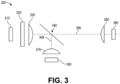
- FIGURE 3 depicts an exemplary differential path length measurement system 300 for measuring gas concentration using absorption spectroscopy.
- Differential path length measurement system 300 comprises light source 310, filter 320, collimating lens 330, beamsplitter 340, reference collection lens 370, reference detector 380, signal collection lens 350, and signal detector 360.
- light source 310 is a light emitting diode (LED), such as, an infrared (IR) light emitting diode.
- LED light emitting diode
- IR infrared
- other embodiments can have light emitting diodes having shorter wavelengths, such as that in the visible or ultraviolet regime.
- a plurality of multiple wavelengths can be used.
- Any suitable, compact light producing device is not beyond the scope of the present disclosure-whether, broadband lamps, coherent, incandescent, incoherent bulb, lasers, or even thermal black-body radiation, etc.
- filter 320 is a dichroic filter, at least in part.
- a dichroic filter, thin-film filter, or interference filter is a very accurate color filter used to selectively pass light of a small range of colors while reflecting other colors.
- dichroic mirrors and dichroic reflectors tend to be characterized by the color(s) of light that they reflect, rather than the color(s) they pass.
- interference filters are used in the present embodiment, other optical filters are not beyond the scope of the present invention, such as, interference, absorption, diffraction, grating, Fabry-Perot, etc.
- An interference filter consists of multiple thin layers of dielectric material having different refractive indices. There also may be metallic layers.
- interference filters comprise also etalons that could be implemented as tunable interference filters. Interference filters are wavelength-selective by virtue of the interference effects that take place between the incident and reflected waves at the thin-film boundaries.
- a color wheel with an optical chopper can be used as the filter 320, pursuant the previous example associated with Figure 2 .
- Collimating lens 330 is a collimator.
- a collimator may consist of a curved mirror or lens with some type of light source and/or an image at its focus. This can be used to replicate a target focused at infinity with little or no parallax.
- the purpose of the collimating lens 330 is to direct the light rays in coaxial light path toward beamsplitter 340.
- Beamsplitter 340 is a beamsplitter which is known in the art.
- a beam splitter (or beamsplitter) is an optical device that splits a beam of light in two. It is a crucial part of many optical experimental and measurement systems, such as interferometers, also finding widespread application in fiber optic telecommunications.
- a beamsplitter 340 is made from two triangular glass prisms which are glued together at their base using polyester, epoxy, or urethane-based adhesives. The thickness of the resin layer is adjusted such that (for a certain wavelength) half of the light incident through one "port" (i.e., face of the cube) is reflected and the other half is transmitted due to frustrated total internal reflection.
- Polarizing beam splitters such as the Wollaston prism, use birefringent materials to split light into two beams of orthogonal polarization states.
- beamsplitter 340 is a half-silvered mirror.
- This comprises an optical substrate, which is often a sheet of glass or plastic, with a partially transparent thin coating of metal.
- the thin coating can be aluminum deposited from aluminum vapor using a physical vapor deposition method. The thickness of the deposit is controlled so that part (typically half) of the light which is incident at a 45-degree angle and not absorbed by the coating or substrate material is transmitted, and the remainder is reflected.
- a very thin half-silvered mirror used in photography is often called a pellicle mirror, which can also be used in some embodiments.
- pellicle mirror To reduce loss of light due to absorption by the reflective coating, so-called "swiss cheese” beam splitter mirrors have been used. Originally, these were sheets of highly polished metal perforated with holes to obtain the desired ratio of reflection to transmission. Later, metal was sputtered onto glass so as to form a discontinuous coating, or small areas of a continuous coating were removed by chemical or mechanical action to produce a very literally "half-silvered" surface.
- a dichroic optical coating may be used instead of a metallic coating.
- a dichroic optical coating may be used instead of a metallic coating.
- the ratio of reflection to transmission will vary as a function of the wavelength of the incident light.
- Dichroic mirrors are used in some ellipsoidal reflector spotlights to split off unwanted infrared (heat) radiation, and as output couplers in laser construction.
- a third version of the beamsplitter 340 is a dichroic mirrored prism assembly which uses dichroic optical coatings to divide an incoming light beam into a number of spectrally distinct output beams.
- a dichroic mirrored prism assembly which uses dichroic optical coatings to divide an incoming light beam into a number of spectrally distinct output beams.
- Such a device was used in three-pickup-tube color television cameras and the three-strip Technicolor movie camera. It is currently used in modern three-CCD cameras.
- An optically similar system is used in reverse as a beam-combiner in three-LCD projectors, in which light from three separate monochrome LCD displays is combined into a single full-color image for projection.
- collimated light coming from collimating lens 330 get bifurcated into two beams, 395, 390.
- Beam 395 is used as the reference beam, which beam 390 is used as the signal beam.
- Their geometries are known, as well as their respective pathlengths. The significance of which will be described in greater detail later in the disclosure.
- reference collection lens 370 and signal collection lens 350 are optical lenses.
- An optical lens is a transmissive optical device that focuses or disperses a light beam by means of refraction.
- a simple lens consists of a single piece of transparent material, while a compound lens consists of several simple lenses (elements), usually arranged along a common axis. Lenses are made from materials such as glass or plastic, and are ground and polished or molded to a desired shape.
- a lens can focus light to form an image, unlike a prism, which refracts light without focusing.
- Devices that similarly focus or disperse waves and radiation other than visible light are also called lenses, such as microwave lenses, electron lenses, acoustic lenses, or explosive lenses.
- Most lenses are spherical lenses: their two surfaces are parts of the surfaces of spheres. Each surface can be convex (bulging outwards from the lens), concave (depressed into the lens), or planar (flat). The line joining the centers of the spheres making up the lens surfaces is called the axis of the lens.
- the lens is biconvex or plano-convex, a collimated beam of light passing through the lens converges to a spot (a focus) behind the lens.
- the lens is called a positive or converging lens.
- the distance from the lens to the spot is the focal length of the lens, which is commonly represented by f in diagrams and equations.
- An extended hemispherical lens is a special type of plano-convex lens, in which the lens's curved surface is a full hemisphere and the lens is much thickerthan the radius of curvature.
- the lens is biconcave or plano-concave, a collimated beam of light passing through the lens is diverged (spread); the lens is thus called a negative or diverging lens.
- the distance from this point to the lens is the focal length, though it is negative with respect to the focal length of a converging lens.
- Convex-concave (meniscus) lenses can be either positive or negative, depending on the relative curvatures of the two surfaces.
- a negative meniscus lens has a steeper concave surface and is thinner at the center than at the periphery.
- a positive meniscus lens has a steeper convex surface and is thicker at the center than at the periphery.
- An ideal thin lens with two surfaces of equal curvature would have zero optical power, meaning that it would neither converge nor diverge light.
- R R 0 exp ⁇ ⁇ gas c gas ⁇ c 0 ⁇ L
- c gas c 0 + 1 ⁇ gas ⁇ L log R R 0
- FIGURE 4 depicts an exemplary differential path length measurement system 400 for measuring gas concentration using waveguides and alternate optics.
- Differential path length measurement system 400 comprises LED 410, filter 440, collimating lens 430, Fresnel prism 450, reference detector (not shown), signal collection lens 480, and signal detector 490.
- light 420 is emitted from LED 410 in a conical shape-usually 15 to 20 degrees in divergence.
- Collimating lens 430 collimates the light to substantially parallel light ray axes, however, this is not entirely necessary.
- Fresnel prism 450 is a is a Fresnel lens used to split the beam into two pathways.
- a Fresnel lens is a type of composite compact lens originally developed by French physicist Augustin-Jean Fresnel (1788-1827) for lighthouses. It has been called "the invention that saved a million ships.”
- a Fresnel lens can be made much thinner than a comparable conventional lens, in some cases taking the form of a flat sheet.
- a Fresnel lens can capture more oblique light from a light source, thus allowing the light from a lighthouse equipped with one to be visible over greater distances.
- reference light 460 After separation, reference light 460 to a reference detector (not shown), while signal light 470 interacts with ambient gas and travels to collection lens 480. Collection lens 480 focusses the light to signal detector 490 for comparison to reference detector.
- ⁇ itself may be varying at part per thousand per kelvin but relative tracking between the two detectors is easily another two or three orders of magnitude better.
- the error in the ratio of the responsivities is reduced by another two orders of magnitude.
- FIGURE 5 depicts an exemplary differential path length measurement system 500 for measuring gas concentration using waveguides and alternate optics.
- Differential path length measurement system 500 comprises LED 510, filter 540, collimating lens 530, waveguide 550, reference detector 570, reference collection lens 560, signal collection lens 580, and signal detector 590.
- light 520 is emitted from LED 510 in a conical shape-usually 15 to 20 degrees in divergence.
- Collimating lens 530 collimates the light to substantially parallel light ray axes, however, this is not entirely necessary.
- waveguide 550 is a hollow waveguide which is coupled to two more waveguides which serve to beam split the incoming light.
- a waveguide is a structure that guides waves, such as electromagnetic waves or sound, with minimal loss of energy by restricting the transmission of energy to one direction. Without the physical constraint of a waveguide, wave amplitudes decrease according to the inverse square law as they expand into three-dimensional space.
- waveguides for different types of waves.
- the original and most common meaning is a hollow conductive metal pipe used to carry high frequency radio waves, particularly microwaves.
- Dielectric waveguides are used at higher radio frequencies, and transparent dielectric waveguides and optical fibers serve as waveguides for light.
- air ducts and horns are used as waveguides for sound in musical instruments and loudspeakers, and specially-shaped metal rods conduct ultrasonic waves in ultrasonic machining.
- each waveguide has a cutoff wavelength determined by its size and will not conduct waves of greater wavelength; an optical fiber that guides light will not transmit microwaves which have a much larger wavelength.
- FIGURE 6 illustrates an exemplary 3-dimensional perspective of a differential path length measurement system 600 for measuring gas concentration using an optical conic-section cap.
- Differential path length measurement system 600 comprises light source 610, reflector 620, reference detector 630, primary signal reflector 660, secondary reflector 640, and signal detector 650.
- the differential path length measurement apparatus 600 uses two different reflective surfaces disposed close to one another, rather than some beam splitting optic, e.g., PBS, half-wave plate, half-silvered, etc.
- some beam splitting optic e.g., PBS, half-wave plate, half-silvered, etc.
- the reference and signal paths are split using a three-dimensional optical cap which can be packaged onto the printed circuit board (PCB) and chip assembly.
- PCB printed circuit board
- a plurality of photons impinges on an ellipsoid. These consequently get reflected and redirected to one (or more) or its foci, at which a photodetector is disposed.
- the alternate pathway in accordance with FIGURE 6 is the optical signal pathway. While similarly measured, the pathway is longer.
- the optical path length between the signal and the reference pathway is called the effective path length and used for absorption calculations which have previously been described.
- the optical signal pathway a plurality of photons emanating from a light source (e.g., LED, etc.) impinge upon a paraboloid. These consequently get reflected and redirected to its foci, at which a photodetector is disposed.
- any suitable conic-section is not beyond the scope of the present disclosure. Even still, with the use of waveguides or other optics, 2-dimensional substitutes may be used, such that, parabolas and ellipses.
- FIGURES 7 illustrates an exemplary 2-dimensional ray-trace of a differential path length measurement system 700 for measuring gas concentration using an optical conic-section cap, in accordance with others embodiments of the disclosure provided herein.
- Differential path length measurement system 700 comprises light source 710, reflector 760, reference detector 730, filter 715, signal reflector 770, and signal detector 750.
- the differential path length measurement apparatus 700 uses two different reflective surfaces disposed close to one another, rather than some beam splitting optic, e.g., PBS, half-wave plate, half-silvered, etc.
- some beam splitting optic e.g., PBS, half-wave plate, half-silvered, etc.
- light is emitted from light source 710 and projected trough filter 715. It is then subsequently is reflected off of reflector 760 while reference light 720 progresses to reference detector 730.
- Signal light 740 which inherently has a longer pathlength becomes incident on signal reflector 770.
- signal light 740 is measured at signal detector 750 where it is compared to reference detector 730.
- reflector 760 and signal reflector 770 are conic sections.
- a conic section (or simply conic) is a curve obtained as the intersection of the surface of a cone with a plane.
- the three types of conic section are the hyperbola, the parabola, and the ellipse; the circle is a special case of the ellipse, though historically it was sometimes called a fourth type.
- the conic sections in the Euclidean plane have various distinguishing properties, many of which can be used as alternative definitions.
- One such property defines a non-circular conic to be the set of those points whose distances to some particular point, called a focus, and some particular line, called a directrix, are in a fixed ratio, called the eccentricity.
- the type of conic is determined by the value of the eccentricity.
- a conic may be defined as a plane algebraic curve of degree 2; that is, as the set of points whose coordinates satisfy a quadratic equation in two variables. This equation may be written in matrix form, and some geometric properties can be studied as algebraic conditions.
- the three types of conic sections appear quite different, but share many properties.
- the apparent difference vanishes: the branches of a hyperbola meet in two points at infinity, making it a single closed curve; and the two ends of a parabola meet to make it a closed curve tangent to the line at infinity.
- Further extension by expanding the real coordinates to admit complex coordinates, provides the means to see this unification algebraically.
- the reference channel pathway shares the same conic-section reflection surface reflection. However, due to its known pathway towards the reference detection, a calculation of gas absorption can be made. It is noted that the second signal path also reflects upon the conic-section cap but impinges upon the signal detector (main).
- interference filters are used in the present embodiment, other optical filters are not beyond the scope of the present invention, such as, interference, absorption, diffraction, grating, Fabry-Perot, etc.
- An interference filter consists of multiple thin layers of dielectric material having different refractive indices. There also may be metallic layers.
- interference filters comprise also etalons that could be implemented as tunable interference filters. Interference filters are wavelength-selective by virtue of the interference effects that take place between the incident and reflected waves at the thin-film boundaries.
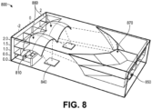
- FIGURE 8 is an isometric view of an exemplary 3-dimensional perspective of a differential path length measurement system 800 for measuring 2 gas concentrations using an optical conic-section cap, in accordance with others embodiments of the disclosure provided herein.
- FIGURE 8 illustrates an exemplary 3-dimensional perspective of a differential path length measurement system for measuring 2 gas concentrations using an optical conic-section cap, in accordance with others embodiments of the disclosure provided herein.
- a plurality of source and corresponding filters get reflected off a multi-dimensional configuration similarto that depicted in FIGURE 7 .
- this can be used to detect multiple gases using a single detector, provided suitable filtering at the light sources. This retains the strategy of using reference channel and main longer path channel which works for more than one gas. As depicted, there are two reference detector sand one main photo-detector.
- the reflective surface of the conic section cap can be made in a variety of ways, all of which are not beyond the scope of the present invention. All conductive/reflective materials remain within the scope of the present disclosure. By way of example, either or both the surfaces exhibit a highly mirrored surface.
- This coating can be performed by, for example but not limited to: direct metal deposition (DMD); laser metal deposition (LMD), thin-film deposition; chemical solution deposition (CSD), chemical bath deposition (CBD), chemical vapor deposition (CVD), plasma enhanced CVD (PECVD), atomic layer deposition (ALD), molecular layer deposition (MLD), physical vapor deposition (PVD), electroplating and sputtering.
- DMD direct metal deposition
- LMD laser metal deposition
- CBD chemical bath deposition
- CVD chemical vapor deposition
- PECVD plasma enhanced CVD
- ALD atomic layer deposition
- MLD molecular layer deposition
- PVD physical vapor deposition
- the reflective materials comprised by the cap surface include, but not limited to: metal, metal alloys, compound metals, semi-conductors, conductive and semi-conductive polymers, conductive and semi-conductive composites, graphene, carbon nanotube, and graphite.
- an LED is used instead of laserto measure the fiber brag grating (FBG) as a sensor.
- Collimating optics are used to control Etendue which is a property of light in an optical system, which characterizes how spread out the light is in area and angle.
- Etendue may be considered to be a volume in phase space.
- Etendue is important because it never decreases in any optical system where optical power is conserved.
- a perfect optical system produces an image with the same etendue as the source.
- the etendue is related to the Lagrange invariant and the optical invariant, which share the property of being constant in an ideal optical system.
- the radiance of an optical system is equal to the derivative of the radiant flux with respect to the etendue.
- detector cover, optical chamber, waveguides and other elements are covered in high conductivity (mirrored) or any other suitable material, e.g., metal, semi-metallic, composite, which are also not beyond the scope of the present disclosure.
- elements can be made of a polymer or silicon and silvered using deposition techniques known in the art.
- a dichroic filter, thin-film filter, or interference filter is used as a very accurate color filter used to selectively pass light of a small range of colors while reflecting other colors.
- dichroic mirrors and dichroic reflectors tend to be characterized by the color(s) of light that they reflect, rather than the color(s) they pass.
- interference filters are used in the present embodiment, other optical filters are not beyond the scope of the present invention, such as, interference, absorption, diffraction, grating, Fabry-Perot, etc.
- An interference filter consists of multiple thin layers of dielectric material having different refractive indices. There also may be metallic layers.
- interference filters comprise also etalons that could be implemented as tunable interference filters. Interference filters are wavelength-selective by virtue of the interference effects that take place between the incident and reflected waves at the thin-film boundaries.
- FIGURE 9 illustrates an exemplary 2-dimensional ray-trace of a differential path length measurement system 900 for measuring 2 gas concentrations using an optical conic-section cap, in accordance with other embodiments of the disclosure provided herein.
- Differential path length measurement system 900 comprises light sources 910, reference detectors 940, signal reflector 970, and signal detector 950. In the present embodiment, two light sources with two different color filters are implemented.
- light sources 910 are different colors which are optimized for different detectable gasses. Specifically, the bandwidth centered at particular frequency is chosen to reflect that of the resonant frequency of a predetermined chemical. That is, the frequency (or wavelength) of light which get absorbed by the chemical of interest.
- This enables the detection of two gasses, each of which having their own reference pathway.
- this can be implement using the same signal detector by alternating the color on and off.
- An ASIC or analog front end (AFE) can them separate the signal and make the appropriate calculation which will be discussed in further detail later in the disclosure.
- An application-specific integrated circuit is an integrated circuit (IC) chip customized for a particular use, rather than intended for general-purpose use.
- IC integrated circuit
- ASIC application-specific integrated circuit
- An analog front-end (AFE or analog front-end controller AFEC) is a set of analog signal conditioning circuitry that uses sensitive analog amplifiers, often operational amplifiers, filters, and sometimes application-specific integrated circuits for sensors, radio receivers, and other circuits to provide a configurable and flexible electronics functional block, needed to interface a variety of sensors to an, antenna, analog to digital converter or in some cases to a microcontroller.
- a single gas is detected, whereas the second pathway is used solely to detect and correct for environmental changes, temperature, gain, current, etc. Again, this obviates the need for factory calibration.
- ⁇ represents optical splitting efficiency of the LED light as portion of the light is sent to the main detector and another portion sent to the reference detector.
- the optical splitting is not cancelled and any changes in the ratio ⁇ Main / ⁇ Ref can't be distinguished from the exponential term representing absorption by the gas.
- the beam splitter (reflectors 860) shifts relative to the LED/PDs due to any reason (e.g. from stress or expansion/contraction due to temperature), it may increase the light going to signal detector 950 and decrease it to reference detectors 940 thus changing the ratio ⁇ Main / ⁇ Ref .
- Another object of this alternate embodiment is to compensate for it also.
- RoR ratio of ratio
- the inventor of the present disclosure has achieved direct calibration free measurement of gas concentration. It only requires the knowledge of optical path length and average gas absorption ⁇ gas . Note that for many popular gases such as CO 2 or CH 4 etc. absorption cross-section can be calculated for a given LED and optical filter.
- 2 nd LED and the 1 st LED after passing through the filter can both have common absorption regions. In which case, the common absorption region will still be cancelled.
- thin film interference coating could be used to collect light at a predetermined incident angle. That is, detectors closer to the septum could have filters which would collect more normal (orthogonal) light. Whereas, detectors further away could be optimized to collect light of lower incident angles, such as, 45-60 degrees. That way, in practice, more weighting could be given to light that has been scattered close by.
- One or more aspects and embodiments of the present application involving the performance of processes or methods may utilize program instructions executable by a device (e.g., a computer, a processor, or other device) to perform, or control performance of, the processes or methods.
- a device e.g., a computer, a processor, or other device
- inventive concepts may be embodied as a computer readable storage medium (or multiple computer readable storage media) (e.g., a computer memory, one or more floppy discs, compact discs, optical discs, magnetic tapes, flash memories, circuit configurations in Field Programmable Gate Arrays or other semiconductor devices, or other tangible computer storage medium) encoded with one or more programs that, when executed on one or more computers or other processors, perform methods that implement one or more of the various embodiments described above.
- a computer readable storage medium e.g., a computer memory, one or more floppy discs, compact discs, optical discs, magnetic tapes, flash memories, circuit configurations in Field Programmable Gate Arrays or other semiconductor devices, or other tangible computer storage medium
- the computer readable medium or media may be transportable, such that the program or programs stored thereon may be loaded onto one or more different computers or other processors to implement various ones of the aspects described above.
- computer readable media may be non-transitory media.
- teachings of the present disclosure may be encoded into one or more tangible, non-transitory computer-readable mediums having stored thereon executable instructions that, when executed, instruct a programmable device (such as a processor or DSP) to perform the methods or functions disclosed herein.
- a programmable device such as a processor or DSP
- a non-transitory medium could include a hardware device hardware-programmed with logic to perform the methods or functions disclosed herein.
- the teachings could also be practiced in the form of Register Transfer Level (RTL) or other hardware description language such as VHDL or Verilog TM , which can be used to program a fabrication process to produce the hardware elements disclosed.
- RTL Register Transfer Level
- VHDL Verilog TM
- processing activities outlined herein may also be implemented in software.
- one or more of these features may be implemented in hardware provided external to the elements of the disclosed figures, or consolidated in any appropriate manner to achieve the intended functionality.
- the various components may include software (or reciprocating software) that can coordinate in order to achieve the operations as outlined herein.
- these elements may include any suitable algorithms, hardware, software, components, modules, interfaces, or objects that facilitate the operations thereof.
- Any suitably-configured processor component can execute any type of instructions associated with the data to achieve the operations detailed herein.
- Any processor disclosed herein could transform an element or an article (for example, data) from one state or thing to another state or thing.
- some activities outlined herein may be implemented with fixed logic or programmable logic (for example, software and/or computer instructions executed by a processor) and the elements identified herein could be some type of a programmable processor, programmable digital logic (for example, an FPGA, an erasable programmable read only memory (EPROM), an electrically erasable programmable read only memory (EEPROM)), an ASIC that includes digital logic, software, code, electronic instructions, flash memory, optical disks, CD-ROMs, DVD ROMs, magnetic or optical cards, othertypes of machine-readable mediums suitable for storing electronic instructions, or any suitable combination thereof.
- EPROM erasable programmable read only memory
- EEPROM electrically erasable programmable read only memory
- processors may store information in any suitable type of non-transitory storage medium (for example, random access memory (RAM), read only memory (ROM), FPGA, EPROM, electrically erasable programmable ROM (EEPROM), etc.), software, hardware, or in any other suitable component, device, element, or object where appropriate and based on particular needs.
- RAM random access memory
- ROM read only memory
- FPGA field-programmable gate array
- EPROM electrically erasable programmable ROM
- EEPROM electrically erasable programmable ROM
- any of the memory items discussed herein should be construed as being encompassed within the broad term 'memory.
- any of the potential processing elements, modules, and machines described herein should be construed as being encompassed within the broad term 'microprocessor' or 'processor.
- the processors, memories, network cards, buses, storage devices, related peripherals, and other hardware elements described herein may be realized by a processor, memory, and other related devices configured by software or firmware to emulate or virtualize the functions of those hardware elements.
- a computer may be embodied in any of a number of forms, such as a rack-mounted computer, a desktop computer, a laptop computer, or a tablet computer, as non-limiting examples. Additionally, a computer may be embedded in a device not generally regarded as a computer but with suitable processing capabilities, including a personal digital assistant (PDA), a smart phone, a mobile phone, an iPad, or any other suitable portable or fixed electronic device.
- PDA personal digital assistant
- a computer may have one or more input and output devices. These devices can be used, among other things, to present a user interface. Examples of output devices that may be used to provide a user interface include printers or display screens for visual presentation of output and speakers or other sound generating devices for audible presentation of output. Examples of input devices that may be used for a user interface include keyboards, and pointing devices, such as mice, touch pads, and digitizing tablets. As another example, a computer may receive input information through speech recognition or in other audible formats.
- Such computers may be interconnected by one or more networks in any suitable form, including a local area network or a wide area network, such as an enterprise network, and intelligent network (IN) or the Internet.
- networks may be based on any suitable technology and may operate according to any suitable protocol and may include wireless networks or wired networks.
- Computer-executable instructions may be in many forms, such as program modules, executed by one or more computers or other devices.
- program modules include routines, programs, objects, components, data structures, etc. that performs particular tasks or implement particular abstract data types.
- functionality of the program modules may be combined or distributed as desired in various embodiments.
- program or “software” are used herein in a generic sense to refer to any type of computer code or set of computer-executable instructions that may be employed to program a computer or other processor to implement various aspects as described above. Additionally, it should be appreciated that according to one aspect, one or more computer programs that when executed perform methods of the present application need not reside on a single computer or processor, but may be distributed in a modular fashion among a number of different computers or processors to implement various aspects of the present application.
- data structures may be stored in computer-readable media in any suitable form.
- data structures may be shown to have fields that are related through location in the data structure. Such relationships may likewise be achieved by assigning storage for the fields with locations in a computer-readable medium that convey relationship between the fields.
- any suitable mechanism may be used to establish a relationship between information in fields of a data structure, including through the use of pointers, tags or other mechanisms that establish relationship between data elements.
- the software code When implemented in software, the software code may be executed on any suitable processor or collection of processors, whether provided in a single computer or distributed among multiple computers.
- Computer program logic implementing all or part of the functionality described herein is embodied in various forms, including, but in no way limited to, a source code form, a computer executable form, a hardware description form, and various intermediate forms (for example, mask works, or forms generated by an assembler, compiler, linker, or locator).
- source code includes a series of computer program instructions implemented in various programming languages, such as an object code, an assembly language, or a high-level language such as OpenCL TM , RTL, Verilog TM , VHDL, Fortran TM , C, C++, JAVA TM , or HTML for use with various operating systems or operating environments.
- the source code may define and use various data structures and communication messages.
- the source code may be in a computer executable form (e.g., via an interpreter), or the source code may be converted (e.g., via a translator, assembler, or compiler) into a computer executable form.
- any number of electrical circuits of the FIGURES may be implemented on a board of an associated electronic device.
- the board can be a general circuit board that can hold various components of the internal electronic system of the electronic device and, further, provide connectors for other peripherals. More specifically, the board can provide the electrical connections by which the other components of the system can communicate electrically.
- Any suitable processors (inclusive of digital signal processors, microprocessors, supporting chipsets, etc.), memory elements, etc. can be suitably coupled to the board based on particular configuration needs, processing demands, computer designs, etc.
- FIGURES may be implemented as standalone modules (e.g., a device with associated components and circuitry configured to perform a specific application or function) or implemented as plug-in modules into application-specific hardware of electronic devices.
- some aspects may be embodied as one or more methods.
- the acts performed as part of the method may be ordered in any suitable way. Accordingly, embodiments may be constructed in which acts are performed in an order different than illustrated, which may include performing some acts simultaneously, even though shown as sequential acts in illustrative embodiments.
- references to "A and/or B", when used in conjunction with open-ended language such as “comprising” may refer, in one embodiment, to A only (optionally including elements otherthan B); in another embodiment, to B only (optionally including elements otherthan A); in yet another embodiment, to both A and B (optionally including other elements); etc.
- the phrase "at least one,” in reference to a list of one or more elements, should be understood to mean at least one element selected from any one or more of the elements in the list of elements, but not necessarily including at least one of each and every element specifically listed within the list of elements and not excluding any combinations of elements in the list of elements.
- This definition also allows that elements may optionally be present other than the elements specifically identified within the list of elements to which the phrase "at least one" refers, whether related or unrelated to those elements specifically identified.
- At least one of A and B may refer, in one embodiment, to at least one, optionally including more than one, A, with no B present (and optionally including elements other than B); in another embodiment, to at least one, optionally including more than one, B, with no A present (and optionally including elements other than A); in yet another embodiment, to at least one, optionally including more than one, A, and at least one, optionally including more than one, B (and optionally including other elements); etc.
- the term "between” is to be inclusive unless indicated otherwise.
- “between A and B” includes A and B unless indicated otherwise.
Landscapes
- Physics & Mathematics (AREA)
- Spectroscopy & Molecular Physics (AREA)
- Chemical & Material Sciences (AREA)
- Health & Medical Sciences (AREA)
- General Physics & Mathematics (AREA)
- Life Sciences & Earth Sciences (AREA)
- Analytical Chemistry (AREA)
- Biochemistry (AREA)
- Pathology (AREA)
- Immunology (AREA)
- General Health & Medical Sciences (AREA)
- Engineering & Computer Science (AREA)
- Medicinal Chemistry (AREA)
- Food Science & Technology (AREA)
- Combustion & Propulsion (AREA)
- Business, Economics & Management (AREA)
- Emergency Management (AREA)
- Toxicology (AREA)
- Investigating Or Analysing Materials By Optical Means (AREA)
Claims (5)
- Détecteur de gaz optique à longueur de trajet différentielle (700), comprenant :un source de lumière (710) pour produire une première lumière ;un filtre de lumière (715) disposé de manière proximale par rapport à la source de lumière (710) ;un élément optique de division de faisceau (760) configuré pour diviser la première lumière en deux trajectoires, comprenant une première trajectoire d'une deuxième lumière (720) et une deuxième trajectoire d'une troisième lumière (740), après avoir traversé le filtre de lumière (715) ;un premier photodétecteur (730) configuré pour mesurer la deuxième lumière (720), dans lequel le premier photodétecteur (730) est agencé de telle sorte que le trajet suivi par la deuxième lumière (720) présente une longueur de trajet plus courte que le trajet suivi par la troisième lumière (740) ;un second photodétecteur (750) configuré pour mesurer la troisième lumière (740), dans lequel le second photodétecteur (750) est agencé de telle sorte que le trajet suivi par la troisième lumière (740) présente une longueur de trajet plus longue que le trajet suivi par la deuxième lumière (720) ; etun circuit configuré pour calculer un rapport de signaux de mesure à partir des premier et second photodétecteurs (730, 750),dans lequel le circuit est en outre configuré pour déterminer directement une concentration de gaz sur la base du rapport des signaux de mesure et de la connaissance des longueurs de trajet des trajets suivis par la deuxième et la troisième lumière (720, 740) ;dans lequel l'élément optique de division de faisceau (760) comprend un premier élément optique de de section tridimensionnel (760) configurée pour diviser la première lumière dans les deux trajectoires ; etle détecteur de gaz optique à longueur de trajet différentielle comprend en outre un second élément optique à section conique tridimensionnelle (770) configuré pour diriger la troisième lumière (740) vers le second photodétecteur (750).
- Détecteur de gaz optique à longueur de trajet différentielle (700) selon la revendication 1, dans lequel le filtre de lumière (715) est centré au niveau d'une première longueur d'onde prédéterminée.
- Détecteur de gaz optique à longueur de trajet différentielle (700) selon la revendication 1 ou 2, dans lequel le filtre de lumière (715) comprend une pluralité de couleurs.
- Détecteur de gaz optique à longueur de trajet différentielle (700) selon l'une quelconque des revendications précédentes, dans lequel le filtre de lumière est une roue de couleurs entraînée par un découpeur optique.
- Détecteur de gaz optique à longueur de trajet différentielle (700) selon l'une quelconque des revendications précédentes, dans lequel l'élément optique de séparation de faisceau (760) est un réflecteur à section conique présentant une forme d'au moins un parmi un paraboloïde, une ellipse, un ellipsoïde, une hyperbole et un hyperboloïde.
Applications Claiming Priority (2)
| Application Number | Priority Date | Filing Date | Title |
|---|---|---|---|
| US201962859276P | 2019-06-10 | 2019-06-10 | |
| US16/872,758 US11747272B2 (en) | 2019-06-10 | 2020-05-12 | Gas detection using differential path length measurement |
Publications (3)
| Publication Number | Publication Date |
|---|---|
| EP3751255A2 EP3751255A2 (fr) | 2020-12-16 |
| EP3751255A3 EP3751255A3 (fr) | 2021-02-17 |
| EP3751255B1 true EP3751255B1 (fr) | 2024-09-25 |
Family
ID=71083451
Family Applications (1)
| Application Number | Title | Priority Date | Filing Date |
|---|---|---|---|
| EP20179106.8A Active EP3751255B1 (fr) | 2019-06-10 | 2020-06-09 | Détection de gaz par mesure différentielle de la longueur du trajet |
Country Status (2)
| Country | Link |
|---|---|
| US (2) | US11747272B2 (fr) |
| EP (1) | EP3751255B1 (fr) |
Families Citing this family (11)
| Publication number | Priority date | Publication date | Assignee | Title |
|---|---|---|---|---|
| US12494463B2 (en) * | 2020-06-01 | 2025-12-09 | Agency For Science, Technology And Research | Chemical sensor and method of forming the same |
| SE544842C2 (en) * | 2021-01-27 | 2022-12-13 | Gpx Medical Ab | A method and device for rescaling a signal to remove an absorption offset from an optical measurement |
| US11835451B2 (en) * | 2021-03-25 | 2023-12-05 | Asahi Kasei Microdevices Corporation | Gas sensor |
| US12368024B2 (en) | 2021-04-09 | 2025-07-22 | Applied Materials, Inc. | Methods and apparatus for processing a substrate |
| US20240353323A1 (en) * | 2021-07-30 | 2024-10-24 | Analog Devices, Inc. | Differential path length sensing using monolithic, dual-wavelength light emitting diode |
| EP4160564A1 (fr) * | 2021-09-29 | 2023-04-05 | Carrier Corporation | Dispositif pour détecter un gaz combustible |
| CN116183486A (zh) * | 2021-11-26 | 2023-05-30 | 清华大学 | 电调制光源、非色散红外光谱检测系统及气体检测方法 |
| TWI836633B (zh) * | 2022-09-28 | 2024-03-21 | 致茂電子股份有限公司 | 多自由度誤差校正方法及設備 |
| US12523603B2 (en) * | 2023-03-14 | 2026-01-13 | Asahi Kasei Microdevices Corporation | Optical concentration measuring apparatus |
| US20250123204A1 (en) * | 2023-10-12 | 2025-04-17 | Honeywell International Inc. | Optical chamber base with integrated reflective surfaces for particle detection |
| CN119836015A (zh) * | 2025-03-13 | 2025-04-15 | 中国科学院上海技术物理研究所 | 一种范德华光电探测器及其制备方法和应用、非色散红外气体传感器 |
Family Cites Families (68)
| Publication number | Priority date | Publication date | Assignee | Title |
|---|---|---|---|---|
| FR2357888A1 (fr) | 1976-04-01 | 1978-02-03 | Cerberus Ag | Detecteur de fumee |
| US4148022A (en) | 1977-04-28 | 1979-04-03 | Honeywell Inc. | Chemical smoke or pollutant detector |
| USRE32105E (en) * | 1980-12-31 | 1986-04-01 | American District Telegraph Company | Forward scatter smoke detector |
| US4618771A (en) * | 1983-11-14 | 1986-10-21 | Beckman Industrial Corporation | Non-dispersive infrared analyzer having improved infrared source and detecting assemblies |
| US5129401A (en) | 1986-10-17 | 1992-07-14 | Nellcor, Inc. | Method for distinguishing respiratory events in a gas analyzer |
| US4830496A (en) * | 1988-01-22 | 1989-05-16 | General Scanning, Inc. | Interferometer |
| US5382341A (en) | 1992-09-10 | 1995-01-17 | Aroutiounian; Vladimir M. | Method of making smoke detector |
| US5444249A (en) | 1994-02-14 | 1995-08-22 | Telaire Systems, Inc. | NDIR gas sensor |
| US5420440A (en) | 1994-02-28 | 1995-05-30 | Rel-Tek Corporation | Optical obscruation smoke monitor having a shunt flow path located between two access ports |
| US5568129A (en) | 1994-09-08 | 1996-10-22 | Sisselman; Ronald | Alarm device including a self-test reminder circuit |
| JPH08304282A (ja) | 1995-04-28 | 1996-11-22 | Jasco Corp | ガス分析装置 |
| US7119337B1 (en) | 1997-08-04 | 2006-10-10 | Ion Optics, Inc. | Infrared radiation sources, sensors and source combinations, and methods of manufacture |
| JP3740736B2 (ja) | 1995-12-22 | 2006-02-01 | 東陶機器株式会社 | 熱交換器及び熱交換器の運転方法 |
| AU1755597A (en) | 1996-01-29 | 1997-08-20 | Engelhard Sensor Technologies, Inc. | Method for dynamically adjusting fire detection criteria |
| US5957858A (en) | 1996-07-26 | 1999-09-28 | Polestar Technologies, Inc. | Systems and methods for monitoring relative concentrations of different isotopic forms of a chemical species |
| GB9616809D0 (en) | 1996-08-10 | 1996-09-25 | Eev Ltd | Gas monitors |
| SE506942C2 (sv) | 1996-08-28 | 1998-03-02 | Hans Goeran Evald Martin | Gassensor |
| US5781291A (en) | 1996-10-22 | 1998-07-14 | Pittway Corporation | Smoke detectors utilizing a hydrophilic substance |
| US6122042A (en) * | 1997-02-07 | 2000-09-19 | Wunderman; Irwin | Devices and methods for optically identifying characteristics of material objects |
| IL121793A (en) | 1997-09-17 | 2008-06-05 | Lewis Coleman | Isotopic gas analyzer |
| US6067840A (en) * | 1997-08-04 | 2000-05-30 | Texas Instruments Incorporated | Method and apparatus for infrared sensing of gas |
| US6721057B1 (en) * | 1999-03-13 | 2004-04-13 | California Institute Of Technology | Spatially modulated interferometer and beam shearing device therefor |
| US6504614B1 (en) * | 1999-10-08 | 2003-01-07 | Rio Grande Medical Technologies, Inc. | Interferometer spectrometer with reduced alignment sensitivity |
| US6599253B1 (en) | 2001-06-25 | 2003-07-29 | Oak Crest Institute Of Science | Non-invasive, miniature, breath monitoring apparatus |
| US6795182B2 (en) * | 2001-07-06 | 2004-09-21 | Arroyo Optics, Inc. | Diffractive fourier optics for optical communications |
| CA2478611A1 (fr) * | 2002-03-06 | 2003-09-18 | Advanced Photometrics, Inc. | Procede et appareil de codage et d'analyse de rayonnement |
| US7059536B2 (en) | 2002-07-19 | 2006-06-13 | Mestek, Inc. | Air circulation system |
| US7019320B2 (en) * | 2003-10-09 | 2006-03-28 | Raytheon Company | Liquid filled conformal windows and domes |
| DE10360215A1 (de) | 2003-12-20 | 2005-07-28 | Robert Bosch Gmbh | Gassensor |
| US20110178420A1 (en) * | 2010-01-18 | 2011-07-21 | Trent Ridder | Methods and apparatuses for improving breath alcohol testing |
| KR100684903B1 (ko) | 2005-07-15 | 2007-02-20 | 삼성전자주식회사 | 반도체 제조 장치 및 파티클 모니터링 방법 |
| US7259374B2 (en) * | 2005-12-23 | 2007-08-21 | Airware, Inc. | Method for detecting a gas species using a super tube waveguide |
| WO2007080398A1 (fr) | 2006-01-10 | 2007-07-19 | Gas Sensing Solutions Limited | Capteur de gaz de differenciation |
| GB0602320D0 (en) | 2006-02-06 | 2006-03-15 | Gas Sensing Solutions Ltd | Domed gas sensor |
| US7570360B1 (en) * | 2007-02-01 | 2009-08-04 | Bah Holdings, Llc | Optical absorption spectrometer and method for measuring concentration of a substance |
| US7835005B2 (en) | 2008-02-21 | 2010-11-16 | Thermo Fisher Scientific Inc. | Gas analyzer system |
| US7796265B2 (en) | 2008-04-24 | 2010-09-14 | Bah Holdings Llc | Optical absorption gas analyser |
| FR2931555A1 (fr) | 2008-05-20 | 2009-11-27 | Callebaut De Blicquy | Mesureur d'absorption, tel que notamment colorimetre, dans la gamme spectrale visible, infrarouge ou encore ultraviolet, pour l'analyse d'un fluide en transmission |
| KR20100037539A (ko) | 2008-10-01 | 2010-04-09 | 노미 보사이 가부시키가이샤 | 광전식 연기 감지기 |
| KR102032863B1 (ko) | 2009-05-01 | 2019-10-16 | 엑스트랄리스 테크놀로지 리미티드 | 입자 검출기에 대한 향상 |
| WO2010138391A2 (fr) | 2009-05-26 | 2010-12-02 | Invitrox, Inc. | Instrument et procédé de détection optique de particules |
| CA2771627A1 (fr) | 2009-08-21 | 2011-02-24 | Airware, Inc. | Detecteurs de gaz non dispersifs infrarouges (detecteurs ndir) a polarisation d'absorption |
| US8859303B2 (en) | 2010-01-21 | 2014-10-14 | Cambridge Cmos Sensors Ltd. | IR emitter and NDIR sensor |
| US8003945B1 (en) * | 2010-08-25 | 2011-08-23 | Jacob Y Wong | Intrinsically safe NDIR gas sensor in a can |
| JP5906407B2 (ja) | 2011-04-11 | 2016-04-20 | パナソニックIpマネジメント株式会社 | 気体成分検出装置 |
| US20130066173A1 (en) | 2011-09-09 | 2013-03-14 | Nellcor Puritan Bennett Ireland | Venous oxygen saturation systems and methods |
| US8785857B2 (en) * | 2011-09-23 | 2014-07-22 | Msa Technology, Llc | Infrared sensor with multiple sources for gas measurement |
| WO2013131834A1 (fr) * | 2012-03-09 | 2013-09-12 | Carl Zeiss Smt Gmbh | Optique d'éclairage pour la lithographie par projection euv ainsi que système optique comprenant une telle optique d'éclairage |
| US8947244B2 (en) | 2012-04-29 | 2015-02-03 | Valor Fire Safety, Llc | Smoke detector utilizing broadband light, external sampling volume, and internally reflected light |
| CN104919035B (zh) * | 2012-12-21 | 2017-08-11 | 精密公司 | 便携式荧光检测系统和微测定盒 |
| US9804084B2 (en) | 2013-11-11 | 2017-10-31 | Amphenol Thermometrics, Inc. | Optical gas sensor |
| KR101581341B1 (ko) | 2014-02-03 | 2015-12-31 | 한국교통대학교산학협력단 | 복수의 독립된 광 경로를 갖는 광 도파관 및 그를 이용한 광학적 가스센서 |
| US9590140B2 (en) | 2014-07-03 | 2017-03-07 | Sergey Suchalkin | Bi-directional dual-color light emitting device and systems for use thereof |
| US9349279B2 (en) | 2014-08-05 | 2016-05-24 | Google Inc. | Systems and methods for compensating for sensor drift in a hazard detection system |
| US9983126B2 (en) * | 2015-02-06 | 2018-05-29 | Block Engineering, Llc | Quantum cascade laser (QCL) based gas sensing system and method |
| US9903814B2 (en) | 2015-12-31 | 2018-02-27 | Google Llc | Systems and methods for optically coupling optoelectronic components of a hazard detection system to determine a smoke condition of an environment |
| FR3048084A1 (fr) | 2016-02-18 | 2017-08-25 | Commissariat Energie Atomique | Capteur infrarouge non-dispersif pour detecter un gaz. |
| DE102016225344A1 (de) * | 2016-12-16 | 2018-06-21 | Fraunhofer-Gesellschaft zur Förderung der angewandten Forschung e.V. | System zur Analyse von elektromagnetischer Strahlung und Bauelement zur Herstellung desselben |
| KR102531308B1 (ko) * | 2017-05-30 | 2023-05-10 | 아나로그 디바이시즈 인코포레이티드 | 콤팩트한 광학 가스 검출 시스템 및 장치 |
| GB2563581A (en) | 2017-06-16 | 2018-12-26 | Sumitomo Chemical Co | Device |
| DE102017213196A1 (de) | 2017-07-31 | 2019-01-31 | Siemens Aktiengesellschaft | Gasanalysator zur Messung von Stickoxiden und Schwefeldioxid in Abgasen |
| US20190094134A1 (en) | 2017-09-25 | 2019-03-28 | Vyacheslav Solovyov | Compact Optical Gas Sensor with Spatial and Spectral Referense |
| CN111465828B (zh) * | 2017-12-13 | 2023-06-09 | 特里纳米克斯股份有限公司 | 光谱仪设备及系统 |
| EP3511697B1 (fr) * | 2018-01-12 | 2023-07-12 | Drägerwerk AG & Co. KGaA | Dispositif et procédé d'analyse d'un fluide |
| US11073467B2 (en) * | 2018-09-28 | 2021-07-27 | Stmicroelectronics S.R.L. | Miniaturized optical particle detector |
| US11079321B2 (en) * | 2018-09-28 | 2021-08-03 | Stmicroelectronics S.R.L. | NDIR detector device for detecting gases having an infrared absorption spectrum |
| US11150130B2 (en) * | 2019-03-04 | 2021-10-19 | Si-Ware Systems | Compact multi-pass gas cell for multi-gas spectral sensors |
| US11821836B2 (en) * | 2020-07-13 | 2023-11-21 | Analog Devices, Inc. | Fully compensated optical gas sensing system and apparatus |
-
2020
- 2020-05-12 US US16/872,758 patent/US11747272B2/en active Active
- 2020-06-09 EP EP20179106.8A patent/EP3751255B1/fr active Active
-
2022
- 2022-12-15 US US18/066,766 patent/US12228502B2/en active Active
Also Published As
| Publication number | Publication date |
|---|---|
| US11747272B2 (en) | 2023-09-05 |
| EP3751255A3 (fr) | 2021-02-17 |
| US20200386677A1 (en) | 2020-12-10 |
| US12228502B2 (en) | 2025-02-18 |
| EP3751255A2 (fr) | 2020-12-16 |
| US20230120444A1 (en) | 2023-04-20 |
Similar Documents
| Publication | Publication Date | Title |
|---|---|---|
| US12228502B2 (en) | Gas detection using differential path length measurement | |
| US10866185B2 (en) | Compact optical gas detection system and apparatus | |
| US12345632B2 (en) | Fully compensated optical gas sensing system and apparatus | |
| KR101895236B1 (ko) | 가스센서용 광 공동 및 이 광 공동을 갖는 가스센서 | |
| CN110632008B (zh) | 一种多点反射式光电气体传感器探头及光电气体检测装置 | |
| KR101784474B1 (ko) | 파장분할 필터를 이용한 멀티 가스 검출장치 | |
| KR20180021956A (ko) | 포물 반사체를 이용한 광 도파관 및 이를 구비하는 적외선 가스 센서 | |
| US20240353323A1 (en) | Differential path length sensing using monolithic, dual-wavelength light emitting diode | |
| CN104502304B (zh) | 基于虚拟狭缝技术的微型固化近红外光谱仪 | |
| KR101108497B1 (ko) | 적외선 가스 센서 | |
| CN115615919B (zh) | 一种基于三角环形腔的光腔衰荡痕量气体测量系统 | |
| CN114674752A (zh) | 一种多次倍增式气体吸收怀特池 | |
| US7498575B2 (en) | Optical analysis device | |
| CN205786294U (zh) | 多波段多气体检测装置 | |
| CN102230882A (zh) | 一种采用Herroitt多次反射样品室的气体检测平台 | |
| KR102427011B1 (ko) | 비분산방식 가스센서용 광 공동 및 이 광 공동을 갖는 가스센서 | |
| KR101542894B1 (ko) | 적외선 분광용 회전형 간섭계 최적화 방법 | |
| TW201812278A (zh) | 液體濃度的檢測裝置 | |
| KR102334769B1 (ko) | 외부 환경의 영향을 최소화할 수 있는 가스센서용 광 공동 및 이 광 공동을 갖는 가스센서 | |
| US20240405148A1 (en) | Monolithic multi-wavelength optical devices | |
| CN117647878A (zh) | 一种密集光程折叠器件 | |
| CN109283136B (zh) | 具有大量程的光腔 | |
| KR102497757B1 (ko) | 복수의 포물 반사체로 구성된 광 도파관 | |
| CN223955419U (zh) | 一种长光程、低损耗的小型红外气体传感器 | |
| RU2615225C1 (ru) | Устройство для измерения концентрации метана в смеси газов |
Legal Events
| Date | Code | Title | Description |
|---|---|---|---|
| PUAI | Public reference made under article 153(3) epc to a published international application that has entered the european phase |
Free format text: ORIGINAL CODE: 0009012 |
|
| STAA | Information on the status of an ep patent application or granted ep patent |
Free format text: STATUS: THE APPLICATION HAS BEEN PUBLISHED |
|
| AK | Designated contracting states |
Kind code of ref document: A2 Designated state(s): AL AT BE BG CH CY CZ DE DK EE ES FI FR GB GR HR HU IE IS IT LI LT LU LV MC MK MT NL NO PL PT RO RS SE SI SK SM TR |
|
| AX | Request for extension of the european patent |
Extension state: BA ME |
|
| PUAL | Search report despatched |
Free format text: ORIGINAL CODE: 0009013 |
|
| AK | Designated contracting states |
Kind code of ref document: A3 Designated state(s): AL AT BE BG CH CY CZ DE DK EE ES FI FR GB GR HR HU IE IS IT LI LT LU LV MC MK MT NL NO PL PT RO RS SE SI SK SM TR |
|
| AX | Request for extension of the european patent |
Extension state: BA ME |
|
| RIC1 | Information provided on ipc code assigned before grant |
Ipc: G01N 21/3504 20140101AFI20210112BHEP Ipc: G01J 3/42 20060101ALI20210112BHEP Ipc: G01N 21/03 20060101ALN20210112BHEP Ipc: G08B 17/107 20060101ALI20210112BHEP Ipc: G01N 21/31 20060101ALI20210112BHEP Ipc: G01N 33/00 20060101ALI20210112BHEP |
|
| STAA | Information on the status of an ep patent application or granted ep patent |
Free format text: STATUS: REQUEST FOR EXAMINATION WAS MADE |
|
| RAP3 | Party data changed (applicant data changed or rights of an application transferred) |
Owner name: ANALOG DEVICES, INC. |
|
| 17P | Request for examination filed |
Effective date: 20210816 |
|
| RBV | Designated contracting states (corrected) |
Designated state(s): AL AT BE BG CH CY CZ DE DK EE ES FI FR GB GR HR HU IE IS IT LI LT LU LV MC MK MT NL NO PL PT RO RS SE SI SK SM TR |
|
| STAA | Information on the status of an ep patent application or granted ep patent |
Free format text: STATUS: EXAMINATION IS IN PROGRESS |
|
| 17Q | First examination report despatched |
Effective date: 20211007 |
|
| GRAP | Despatch of communication of intention to grant a patent |
Free format text: ORIGINAL CODE: EPIDOSNIGR1 |
|
| STAA | Information on the status of an ep patent application or granted ep patent |
Free format text: STATUS: GRANT OF PATENT IS INTENDED |
|
| RIC1 | Information provided on ipc code assigned before grant |
Ipc: G01N 33/497 20060101ALN20240322BHEP Ipc: G01N 21/03 20060101ALN20240322BHEP Ipc: G08B 17/107 20060101ALI20240322BHEP Ipc: G01J 3/02 20060101ALI20240322BHEP Ipc: G01J 3/42 20060101ALI20240322BHEP Ipc: G01N 33/00 20060101ALI20240322BHEP Ipc: G01N 21/31 20060101ALI20240322BHEP Ipc: G01N 21/3504 20140101AFI20240322BHEP |
|
| INTG | Intention to grant announced |
Effective date: 20240417 |
|
| GRAS | Grant fee paid |
Free format text: ORIGINAL CODE: EPIDOSNIGR3 |
|
| GRAA | (expected) grant |
Free format text: ORIGINAL CODE: 0009210 |
|
| STAA | Information on the status of an ep patent application or granted ep patent |
Free format text: STATUS: THE PATENT HAS BEEN GRANTED |
|
| AK | Designated contracting states |
Kind code of ref document: B1 Designated state(s): AL AT BE BG CH CY CZ DE DK EE ES FI FR GB GR HR HU IE IS IT LI LT LU LV MC MK MT NL NO PL PT RO RS SE SI SK SM TR |
|
| REG | Reference to a national code |
Ref country code: GB Ref legal event code: FG4D |
|
| REG | Reference to a national code |
Ref country code: CH Ref legal event code: EP |
|
| REG | Reference to a national code |
Ref country code: DE Ref legal event code: R096 Ref document number: 602020038201 Country of ref document: DE |
|
| REG | Reference to a national code |
Ref country code: IE Ref legal event code: FG4D |
|
| REG | Reference to a national code |
Ref country code: LT Ref legal event code: MG9D |
|
| PG25 | Lapsed in a contracting state [announced via postgrant information from national office to epo] |
Ref country code: NO Free format text: LAPSE BECAUSE OF FAILURE TO SUBMIT A TRANSLATION OF THE DESCRIPTION OR TO PAY THE FEE WITHIN THE PRESCRIBED TIME-LIMIT Effective date: 20241225 |
|
| PG25 | Lapsed in a contracting state [announced via postgrant information from national office to epo] |
Ref country code: GR Free format text: LAPSE BECAUSE OF FAILURE TO SUBMIT A TRANSLATION OF THE DESCRIPTION OR TO PAY THE FEE WITHIN THE PRESCRIBED TIME-LIMIT Effective date: 20241226 Ref country code: FI Free format text: LAPSE BECAUSE OF FAILURE TO SUBMIT A TRANSLATION OF THE DESCRIPTION OR TO PAY THE FEE WITHIN THE PRESCRIBED TIME-LIMIT Effective date: 20240925 |
|
| PG25 | Lapsed in a contracting state [announced via postgrant information from national office to epo] |
Ref country code: BG Free format text: LAPSE BECAUSE OF FAILURE TO SUBMIT A TRANSLATION OF THE DESCRIPTION OR TO PAY THE FEE WITHIN THE PRESCRIBED TIME-LIMIT Effective date: 20240925 |
|
| PG25 | Lapsed in a contracting state [announced via postgrant information from national office to epo] |
Ref country code: LV Free format text: LAPSE BECAUSE OF FAILURE TO SUBMIT A TRANSLATION OF THE DESCRIPTION OR TO PAY THE FEE WITHIN THE PRESCRIBED TIME-LIMIT Effective date: 20240925 |
|
| PG25 | Lapsed in a contracting state [announced via postgrant information from national office to epo] |
Ref country code: RS Free format text: LAPSE BECAUSE OF FAILURE TO SUBMIT A TRANSLATION OF THE DESCRIPTION OR TO PAY THE FEE WITHIN THE PRESCRIBED TIME-LIMIT Effective date: 20241225 |
|
| REG | Reference to a national code |
Ref country code: NL Ref legal event code: MP Effective date: 20240925 |
|
| PG25 | Lapsed in a contracting state [announced via postgrant information from national office to epo] |
Ref country code: RS Free format text: LAPSE BECAUSE OF FAILURE TO SUBMIT A TRANSLATION OF THE DESCRIPTION OR TO PAY THE FEE WITHIN THE PRESCRIBED TIME-LIMIT Effective date: 20241225 Ref country code: NO Free format text: LAPSE BECAUSE OF FAILURE TO SUBMIT A TRANSLATION OF THE DESCRIPTION OR TO PAY THE FEE WITHIN THE PRESCRIBED TIME-LIMIT Effective date: 20241225 Ref country code: LV Free format text: LAPSE BECAUSE OF FAILURE TO SUBMIT A TRANSLATION OF THE DESCRIPTION OR TO PAY THE FEE WITHIN THE PRESCRIBED TIME-LIMIT Effective date: 20240925 Ref country code: GR Free format text: LAPSE BECAUSE OF FAILURE TO SUBMIT A TRANSLATION OF THE DESCRIPTION OR TO PAY THE FEE WITHIN THE PRESCRIBED TIME-LIMIT Effective date: 20241226 Ref country code: FI Free format text: LAPSE BECAUSE OF FAILURE TO SUBMIT A TRANSLATION OF THE DESCRIPTION OR TO PAY THE FEE WITHIN THE PRESCRIBED TIME-LIMIT Effective date: 20240925 Ref country code: BG Free format text: LAPSE BECAUSE OF FAILURE TO SUBMIT A TRANSLATION OF THE DESCRIPTION OR TO PAY THE FEE WITHIN THE PRESCRIBED TIME-LIMIT Effective date: 20240925 |
|
| REG | Reference to a national code |
Ref country code: AT Ref legal event code: MK05 Ref document number: 1727013 Country of ref document: AT Kind code of ref document: T Effective date: 20240925 |
|
| PG25 | Lapsed in a contracting state [announced via postgrant information from national office to epo] |
Ref country code: NL Free format text: LAPSE BECAUSE OF FAILURE TO SUBMIT A TRANSLATION OF THE DESCRIPTION OR TO PAY THE FEE WITHIN THE PRESCRIBED TIME-LIMIT Effective date: 20240925 |
|
| PG25 | Lapsed in a contracting state [announced via postgrant information from national office to epo] |
Ref country code: IS Free format text: LAPSE BECAUSE OF FAILURE TO SUBMIT A TRANSLATION OF THE DESCRIPTION OR TO PAY THE FEE WITHIN THE PRESCRIBED TIME-LIMIT Effective date: 20250125 Ref country code: PT Free format text: LAPSE BECAUSE OF FAILURE TO SUBMIT A TRANSLATION OF THE DESCRIPTION OR TO PAY THE FEE WITHIN THE PRESCRIBED TIME-LIMIT Effective date: 20250127 |
|
| PG25 | Lapsed in a contracting state [announced via postgrant information from national office to epo] |
Ref country code: RO Free format text: LAPSE BECAUSE OF FAILURE TO SUBMIT A TRANSLATION OF THE DESCRIPTION OR TO PAY THE FEE WITHIN THE PRESCRIBED TIME-LIMIT Effective date: 20240925 Ref country code: SM Free format text: LAPSE BECAUSE OF FAILURE TO SUBMIT A TRANSLATION OF THE DESCRIPTION OR TO PAY THE FEE WITHIN THE PRESCRIBED TIME-LIMIT Effective date: 20240925 |
|
| PG25 | Lapsed in a contracting state [announced via postgrant information from national office to epo] |
Ref country code: ES Free format text: LAPSE BECAUSE OF FAILURE TO SUBMIT A TRANSLATION OF THE DESCRIPTION OR TO PAY THE FEE WITHIN THE PRESCRIBED TIME-LIMIT Effective date: 20240925 |
|
| PG25 | Lapsed in a contracting state [announced via postgrant information from national office to epo] |
Ref country code: EE Free format text: LAPSE BECAUSE OF FAILURE TO SUBMIT A TRANSLATION OF THE DESCRIPTION OR TO PAY THE FEE WITHIN THE PRESCRIBED TIME-LIMIT Effective date: 20240925 Ref country code: AT Free format text: LAPSE BECAUSE OF FAILURE TO SUBMIT A TRANSLATION OF THE DESCRIPTION OR TO PAY THE FEE WITHIN THE PRESCRIBED TIME-LIMIT Effective date: 20240925 |
|
| PG25 | Lapsed in a contracting state [announced via postgrant information from national office to epo] |
Ref country code: CZ Free format text: LAPSE BECAUSE OF FAILURE TO SUBMIT A TRANSLATION OF THE DESCRIPTION OR TO PAY THE FEE WITHIN THE PRESCRIBED TIME-LIMIT Effective date: 20240925 Ref country code: PL Free format text: LAPSE BECAUSE OF FAILURE TO SUBMIT A TRANSLATION OF THE DESCRIPTION OR TO PAY THE FEE WITHIN THE PRESCRIBED TIME-LIMIT Effective date: 20240925 |
|
| PG25 | Lapsed in a contracting state [announced via postgrant information from national office to epo] |
Ref country code: SK Free format text: LAPSE BECAUSE OF FAILURE TO SUBMIT A TRANSLATION OF THE DESCRIPTION OR TO PAY THE FEE WITHIN THE PRESCRIBED TIME-LIMIT Effective date: 20240925 Ref country code: IT Free format text: LAPSE BECAUSE OF FAILURE TO SUBMIT A TRANSLATION OF THE DESCRIPTION OR TO PAY THE FEE WITHIN THE PRESCRIBED TIME-LIMIT Effective date: 20240925 |
|
| REG | Reference to a national code |
Ref country code: DE Ref legal event code: R097 Ref document number: 602020038201 Country of ref document: DE |
|
| PGFP | Annual fee paid to national office [announced via postgrant information from national office to epo] |
Ref country code: DE Payment date: 20250520 Year of fee payment: 6 |
|
| PG25 | Lapsed in a contracting state [announced via postgrant information from national office to epo] |
Ref country code: DK Free format text: LAPSE BECAUSE OF FAILURE TO SUBMIT A TRANSLATION OF THE DESCRIPTION OR TO PAY THE FEE WITHIN THE PRESCRIBED TIME-LIMIT Effective date: 20240925 |
|
| PLBE | No opposition filed within time limit |
Free format text: ORIGINAL CODE: 0009261 |
|
| STAA | Information on the status of an ep patent application or granted ep patent |
Free format text: STATUS: NO OPPOSITION FILED WITHIN TIME LIMIT |
|
| 26N | No opposition filed |
Effective date: 20250626 |
|
| PG25 | Lapsed in a contracting state [announced via postgrant information from national office to epo] |
Ref country code: SE Free format text: LAPSE BECAUSE OF FAILURE TO SUBMIT A TRANSLATION OF THE DESCRIPTION OR TO PAY THE FEE WITHIN THE PRESCRIBED TIME-LIMIT Effective date: 20240925 |
|
| PG25 | Lapsed in a contracting state [announced via postgrant information from national office to epo] |
Ref country code: HR Free format text: LAPSE BECAUSE OF FAILURE TO SUBMIT A TRANSLATION OF THE DESCRIPTION OR TO PAY THE FEE WITHIN THE PRESCRIBED TIME-LIMIT Effective date: 20240925 |
|
| REG | Reference to a national code |
Ref country code: CH Ref legal event code: H13 Free format text: ST27 STATUS EVENT CODE: U-0-0-H10-H13 (AS PROVIDED BY THE NATIONAL OFFICE) Effective date: 20260127 |
|
| PG25 | Lapsed in a contracting state [announced via postgrant information from national office to epo] |
Ref country code: MC Free format text: LAPSE BECAUSE OF FAILURE TO SUBMIT A TRANSLATION OF THE DESCRIPTION OR TO PAY THE FEE WITHIN THE PRESCRIBED TIME-LIMIT Effective date: 20240925 |
|
| PG25 | Lapsed in a contracting state [announced via postgrant information from national office to epo] |
Ref country code: LU Free format text: LAPSE BECAUSE OF NON-PAYMENT OF DUE FEES Effective date: 20250609 |
|
| GBPC | Gb: european patent ceased through non-payment of renewal fee |
Effective date: 20250609 |
|
| REG | Reference to a national code |
Ref country code: BE Ref legal event code: MM Effective date: 20250630 |
|
| PG25 | Lapsed in a contracting state [announced via postgrant information from national office to epo] |
Ref country code: GB Free format text: LAPSE BECAUSE OF NON-PAYMENT OF DUE FEES Effective date: 20250609 |
|
| PG25 | Lapsed in a contracting state [announced via postgrant information from national office to epo] |
Ref country code: IE Free format text: LAPSE BECAUSE OF NON-PAYMENT OF DUE FEES Effective date: 20250609 |
|
| PG25 | Lapsed in a contracting state [announced via postgrant information from national office to epo] |
Ref country code: BE Free format text: LAPSE BECAUSE OF NON-PAYMENT OF DUE FEES Effective date: 20250630 |
|
| PG25 | Lapsed in a contracting state [announced via postgrant information from national office to epo] |
Ref country code: FR Free format text: LAPSE BECAUSE OF NON-PAYMENT OF DUE FEES Effective date: 20250630 |