EP3753407B1 - Appareil agricole à réglage de l'inclinaison amélioré - Google Patents
Appareil agricole à réglage de l'inclinaison amélioré Download PDFInfo
- Publication number
- EP3753407B1 EP3753407B1 EP20401029.2A EP20401029A EP3753407B1 EP 3753407 B1 EP3753407 B1 EP 3753407B1 EP 20401029 A EP20401029 A EP 20401029A EP 3753407 B1 EP3753407 B1 EP 3753407B1
- Authority
- EP
- European Patent Office
- Prior art keywords
- pressure
- actuating device
- boom
- connecting line
- agricultural machine
- Prior art date
- Legal status (The legal status is an assumption and is not a legal conclusion. Google has not performed a legal analysis and makes no representation as to the accuracy of the status listed.)
- Active
Links
Images


Classifications
-
- A—HUMAN NECESSITIES
- A01—AGRICULTURE; FORESTRY; ANIMAL HUSBANDRY; HUNTING; TRAPPING; FISHING
- A01M—CATCHING, TRAPPING OR SCARING OF ANIMALS; APPARATUS FOR THE DESTRUCTION OF NOXIOUS ANIMALS OR NOXIOUS PLANTS
- A01M7/00—Special adaptations or arrangements of liquid-spraying apparatus for purposes covered by this subclass
- A01M7/005—Special arrangements or adaptations of the spraying or distributing parts, e.g. adaptations or mounting of the spray booms, mounting of the nozzles, protection shields
- A01M7/0053—Mounting of the spraybooms
- A01M7/0057—Mounting of the spraybooms with active regulation of the boom position
-
- A—HUMAN NECESSITIES
- A01—AGRICULTURE; FORESTRY; ANIMAL HUSBANDRY; HUNTING; TRAPPING; FISHING
- A01M—CATCHING, TRAPPING OR SCARING OF ANIMALS; APPARATUS FOR THE DESTRUCTION OF NOXIOUS ANIMALS OR NOXIOUS PLANTS
- A01M7/00—Special adaptations or arrangements of liquid-spraying apparatus for purposes covered by this subclass
- A01M7/005—Special arrangements or adaptations of the spraying or distributing parts, e.g. adaptations or mounting of the spray booms, mounting of the nozzles, protection shields
- A01M7/0071—Construction of the spray booms
- A01M7/0075—Construction of the spray booms including folding means
Definitions
- the invention relates to an agricultural device. Furthermore, the invention relates to a method for controlling and/or regulating an agricultural device.
- the agricultural equipment for spreading materials such as fertilizers, pesticides or seeds, for example field sprayers.
- the agricultural equipment has a distribution boom with several application elements, such as spray nozzles.
- the distribution boom extends across the direction of travel and can have working widths of up to 40 m.
- the distance between the distribution boom and the ground should remain as constant as possible across the entire working width of the distribution boom. This means that the distribution boom is kept as parallel as possible to the soil to be worked, even if the soil to be worked is uneven.
- devices which have a pendulum suspension and inclination sensors or distance sensors and which attempt to set the constant distance to the ground using adjusting devices.
- the inclination adjustment of the booms of the distribution boom is often carried out by hydraulic cylinders and spring-damper systems that are connected to the respective boom.
- hydraulic cylinders and spring-damper systems that are connected to the respective boom.
- FR 2 795 913 A1 , EP 1 167 095 A1 and EP 0 922 385 A1 The known controls use the distance between the boom and the ground and/or the relative angle between the boom and the tractor as measurement variables.
- the known controls have the disadvantage that they are inaccurate and do not allow real-time control.
- the field sprayer has EP 1 444 894 A1 a multi-link suspension in which both the signals from the distance measurement between the boom and the ground and inclination signals that measure the relative inclination between the vehicle and the boom reproduce, are included in the regulation.
- the boom is mounted on a height-adjustable lifting frame so that it can rotate about a rotation axis pointing in the direction of travel.
- a rotating intermediate frame is attached to the lifting frame coaxially to the boom.
- the intermediate frame and the boom are coupled to one another by two centering springs and a damper.
- a hydraulic cylinder is provided between the intermediate frame and the lifting frame.
- the hydraulic cylinder is extended or retracted and rotates the intermediate frame relative to the lifting frame. This lengthens one of the two centering springs and shortens the other.
- the spring force acting on the boom pulls the boom in line with the movement of the intermediate frame so that it is centered again in the inclined end position in relation to the intermediate frame.
- the centering springs also compensate for rapid relative movements between the vehicle and the boom so that the boom remains stable during operation.
- the inclination control system uses signals from the ground clearance measurement between the boom and the ground and an inclination signal that is a measure of the spring force acting on the boom. This allows the hydraulic cylinder to be controlled precisely. Oversteering of the boom is largely avoided.
- Adjusting the damping to reduce unwanted movements in or against the direction of travel reveals EN 10 2017 104 814 A1 .
- the object of the present invention is therefore to provide an agricultural device with improved inclination control.
- a further object of the invention is to provide a method for controlling an agricultural device.
- the agricultural device can be a field sprayer in particular.
- the field sprayer can be self-propelled. It can also be a towed or carried field sprayer.
- the hydraulic connection line achieves a direct coupling of the two hydraulic actuating elements. In other words, a force applied to one of the two actuating elements can be transmitted to the other actuating element. Since each of the control devices and the connecting line is assigned a pressure control valve, a flexible inclination control of the distributor rod is possible This means that the system allows both booms to be angled up and down together, one boom to be angled up and down selectively, and the entire distribution boom to be tilted, simply by controlling the pressure control and shut-off valves.
- the bending and angling of a boom is understood to mean a rotational movement of the boom around the respective axis of rotation.
- bending and angling causes a change in the angle of the respective boom compared to the horizontal.
- Tilting the distribution boom accordingly refers to bending one boom while bending the other boom accordingly.
- a synchronous bending or angling of the two booms can be achieved as follows:
- the pressure control valves assigned to the respective adjusting devices are controlled in order to generate a pressure on the adjusting devices, which results in the boom being bent or angled.
- the movement of the adjusting devices transfers a corresponding pressure to the fluid in the hydraulic connecting line.
- fluid can flow out of the hydraulic connecting line or into the hydraulic connecting line.
- a selective bending or angling of just one boom can be achieved in a similar way.
- the pressure control valve of the boom in question is controlled to supply the corresponding actuating device with a pressure that leads to the bending or angling of the boom in question.
- the movement of the actuating device in turn transfers a corresponding pressure to the fluid in the hydraulic connecting line.
- fluid can flow out of the hydraulic connecting line or into the hydraulic connecting line.
- the other actuating device, and thus the other boom, are not affected, since any pressure transfer to the hydraulic connecting line is compensated by the fluid flowing out of the connecting line.
- the pressure control valve of the other actuating device can be controlled to maintain the applied pressure. This keeps the other boom in its current position.
- the system also makes it possible to tilt the entire distribution rod.
- the pressure control valve of one of the booms is controlled to supply the corresponding adjusting device with a pressure that leads to this boom being angled up or down.
- the pressure control valve of the other boom is also controlled to supply the corresponding adjusting device with a pressure that leads to this boom being angled up or down.
- the pressure control valve of the hydraulic connecting line can be controlled to maintain the pressure there.
- the adjusting devices thus communicate hydraulically, which leads to a uniform, joint rotational movement of the two booms.
- first actuating device, the second actuating device and the connecting line can each be assigned a shut-off valve associated with the respective pressure control valve.
- a shut-off valve can be used in particular to prevent hydraulic fluid from flowing out of the respective actuating device or the connecting line. This allows the respective booms to be locked in a desired position. This can be desirable, for example, in situations such as road transport or when folding in and out the distributor rod, in which the distributor rod is to be rigidly connected to the agricultural device via the actuating device.
- shut-off valves can also be used during the bending or tilting processes described above.
- shut-off valve This makes it possible for the associated shut-off valve to be closed during selective bending or angling for the other adjusting device as an alternative or in addition to setting a pressure on the pressure control valve. This locks the corresponding boom and ensures that bending or angling one boom has no effect on the other boom.
- shut-off valves are assigned to the pressure control valves, these can be closed after the bending or tilting has ended in order to lock the actuating devices in a desired actuating state.
- the hydraulic devices can also be assigned one or more pressure sensors.
- the pressure sensors can be used as pressure sensors for direct pressure measurement, in particular as a pressure transducer. Such a design has the advantage that both a relative pressure and an absolute pressure can be determined.
- the pressure sensors can preferably be designed as differential pressure transducers for determining a differential pressure or an occurring pressure difference.
- the pressure transducers can detect the pressure to be measured via a measuring membrane, which is mechanically deformed depending on the respective pressure. This mechanical change can be measured electronically, output as an analog or digital output signal and transmitted to the control unit, for example.
- the respective booms can be made up of several parts. They can comprise foldable segments that can be moved around an axis that runs perpendicular to the direction of travel. The booms can also be folded in and out segment by segment. They can also assume intermediate positions. This makes it possible to adjust the working width of the agricultural equipment by folding out a certain number of segments. This can be done for one boom independently of the other boom. Sensors, in particular potentiometers, can be attached to the joints between the foldable segments to determine the folding states. These sensors can detect both fully folded in/out segments and intermediate positions at the joints between adjacent segments, and transmit the respective folding state to the control unit.
- the hydraulic actuating devices and the hydraulic connecting line can be connected to a hydraulic circuit via the pressure control valves and the associated shut-off valves.
- the hydraulic circuit can be an open circuit that includes, for example, a pump and a hydraulic tank.
- the control unit can be configured in such a way that the pressure control valves are adjusted to an associated starting target pressure when the shut-off valves are opened.
- a starting target pressure can, for example, be stored in a memory assigned to the control unit.
- the pressure control valves can be designed to maintain a consumer-side pressure as a function of an electrical control signal, in particular control current.
- the pressure control valve is then, for example, a directly controlled and spring-loaded three-way valve, for example in a slide design.
- the pressure at the consumer is relieved to the tank.
- the maximum control signal the maximum possible pressure (either the pressure supply or the maximum value of the pressure control valve) is regulated to the consumer.
- the spring load in the valve is electromagnetically counteracted and the pressure on the consumer side is kept constant in accordance with the control characteristic of the valve.
- the set pressure is then proportional to the control signal, which is in particular a control current.
- a proportional control characteristic is not absolutely necessary and can be replaced by a non-proportional control, for example for cost reasons.
- any control characteristic can be stored in the control unit in order to calculate and output control signals that match individual target pressure values.
- the valves can in particular comprise a valve body with a control piston, a return spring and a solenoid coil with a magnet armature for electrical actuation.
- the magnet armature can press on the control piston with a force corresponding to the signal. This allows oil to flow through the valve and pressure to be built up or reduced, whereby the actuating device can be activated. This continues until the applied pressure corresponds to the target pressure according to the electrical signal.
- proportional pressure control valves work is based on regulating a pressure difference that occurs. If a preset pressure level is not reached, the valve automatically supplies oil from the hydraulic reservoir until the setpoint is reached again. Otherwise, if the pressure level is too high, oil is drained.
- proportional pressure control valves offer efficient control and stability properties, as well as low hysteresis of the valves, which can occur due to friction and magnetization. Furthermore, proportional valves enable space-saving installation, as well as easy assembly and interchangeability.
- the pressure control valves can be electronically controlled to a setpoint using a known characteristic curve.
- the characteristic curves describe, for example, the relationship between a pressure that occurs and the associated electrical current required on a control coil of the valve.
- the pressure sensors described above can be used to a setpoint value for the pressure control valves can be determined, whereby a control current is switched to the valves based on the characteristic curve in order to set the corresponding pressure.
- This has the advantage that the pressure on the distributor rod can be precisely adjusted to a setpoint value using the characteristic curve of the pressure control valves.
- Such a setpoint value can also correspond to one of the start setpoint pressure values mentioned above.
- the agricultural device can further comprise a sensor device assigned to a boom for detecting a vertical acceleration of the respective boom acting on the respective boom.
- a vertical acceleration can occur, for example, when the agricultural device drives over an obstacle, such as an uneven ground.
- Measuring the vertical acceleration makes it possible to determine the forces acting on the boom due to such a vertical acceleration. From these, conclusions can be drawn about the forces acting on a hydraulic actuating device assigned to the respective boom. This makes it possible to determine the pressure that should be set on the pressure control valve in response to these forces, in particular to compensate for these forces.
- the sensor device can, for example, comprise an acceleration sensor for detecting the vertical accelerations. It can also comprise a rotation rate sensor.
- the acceleration sensor and the rotation rate sensor can be separate sensors. Alternatively, it can be a combined rotation rate and acceleration sensor.
- the acceleration sensor can be attached to the agricultural device. Alternatively or additionally, a combined rotation rate and acceleration sensor can be located on the respective boom.
- the acceleration sensor can be attached close to the respective axis of rotation of the boom, where close here means that the distance of the sensor to the axis of rotation is less than 0.5 m, in particular less than 0.1 m. In such a configuration, the sensor detects almost no accelerations that result from a rotational movement of the boom.
- IMU inertial measuring units
- the acceleration sensor can be attached to the boom at a specified distance from the respective axis of rotation.
- the distance to the axis of rotation refers to the normal distance of the attachment point from the axis of rotation.
- the distance can be between 1 m and 3 m, in particular between 1 m and 2 m.
- Such an arrangement of the sensor makes it possible to determine both the vertical acceleration of the boom and, since the distance between the pivot point and the sensor is known, also the rotational acceleration of the boom. This is advantageous because it enables a closed control loop to be implemented for the acceleration acting on the boom.
- the target acceleration for such a control loop can in particular be 0 m/s 2 or the acceleration due to gravity, i.e. 9.81 m/s 2. IMUs can also be used here.
- the sensor device can comprise one or more additional sensors.
- the sensor device can comprise further sensors for measuring a distance of the boom from the ground.
- Such sensors can be designed, for example, as ultrasonic distance sensors.
- the sensor device can comprise sensors for determining a rotation rate of the boom.
- the sensor device can comprise further sensors on the distributor rod, which are configured to determine a rotation about a folding axis and/or a position of a rod section and/or boom.
- These sensors can be designed, for example, as potentiometers. The potentiometer determines whether an individual rod section or the entire boom is deflected from its target position and how its position or location changes.
- the control unit can be configured to control the pressure control valves based on values from the sensor device. This allows the position of the respective boom to be controlled based on the Measured values can be controlled. In particular, deviations from the target position of the boom can be corrected, especially during the device's operation.
- the combination of different measured values in the data processing unit enables very precise adjustment of the control devices or pressure control valves.
- the control unit can also be configured to control the pressure control valves, in particular by means of a PID controller, in such a way that a setpoint value of the vertical acceleration acts on the respective boom.
- the control unit can control the pressure valves in such a way that the vertical acceleration acting on the respective boom is regulated to 0 m/s 2 or 9.81 m/s 2. This allows the transmission of force from the boom to the middle section of the device to be minimized.
- the control unit can be configured to continuously record and process the measurement data of the sensor device at regular time intervals.
- the time intervals can be the same for all sensors of the sensor device. However, they can also be different for different sensors.
- the time intervals are preferably between 5ms and 1s, preferably between 5ms and 100ms.
- the control unit can be configured to filter the measurement data using a filter, for example a PT1 element. By choosing a suitable time constant, measurement noise can be suppressed, for example.
- the first and second actuating devices can each be designed as hydraulic cylinders, in particular as double-acting hydraulic cylinders. Such cylinders form inexpensive and simple means for controlling the distributor rod.
- the double-acting hydraulic cylinders can, for example, each be designed with a piston which can be pressurized on both sides.
- the connecting line can connect the piston-side chambers of the first and second actuating devices.
- the respective pressure control and shut-off valves of the first and second actuating devices are assigned to the respective rod-side chambers. This means that the pressure in the piston-side chambers can be set jointly for the first and second actuating devices using the pressure in the connecting line.
- the respective pressure control valves can be controlled independently of each other. This means that the pressure control valves can each be controlled independently via an electronic signal from the control unit. Therefore, the control is efficient for both symmetrical and asymmetrical folding states of the distributor rod. In asymmetrical folding states with asymmetrical working widths, different pressure conditions inevitably prevail at the two pressure control valves due to the different mass distribution. Thanks to their independent adjustability, an asymmetrical distribution rod can also be reliably held in the desired, particularly horizontal, position above the ground.
- the respective adjusting devices can also be suitable for transferring the respective boom from a transport position to a working position and vice versa.
- a transport position is understood to mean a position of the boom in which the boom is completely angled to the agricultural implement.
- the distribution boom can be set to any folding state.
- the respective target pressures can be determined by the control unit based on the respective target folding state of the respective boom. After these target pressures have been set, the respective booms are transferred to the respective folding state.
- a shut-off valve associated with the connecting line can also be closed after setting the first target pressure, setting the second target pressure can include increasing the pressure at the first adjusting device, and setting the third target pressure can include a corresponding reduction in the pressure at the second adjusting device. In this way, it can be achieved that the entire distributor rod is tilted by a certain angle, as described above.
- a shut-off valve assigned to the connecting line can remain open after the first target pressure has been set. In this way, the booms can be angled up or down simultaneously, as described above.
- the adjusted pressure value is determined in such a way that it compensates as much as possible for the force acting on the actuating device.
- the method can further comprise detecting a distance of the boom from the ground. This can be done, for example, using ultrasonic distance sensors. Additionally or alternatively, the method can comprise determining a rotation rate of the boom. Additionally or alternatively, the method can comprise detecting a rotation about a folding axis and/or a position of a rod section and/or boom. This can be done, for example, using potentiometers.
- the method can further comprise controlling the control valves based on the detection of one or more of the aforementioned measured values. In particular, the control can be carried out using setpoints for one or more of the aforementioned measured values. In other words, the method can comprise control based on these setpoints.
- the adjusted pressure values can be determined, in particular by means of a PID circuit, such that a setpoint for the vertical acceleration acts on the boom.
- an agricultural device for spreading material comprising a distributor rod that can be folded on both sides and has a central part and two lateral booms connected to the central part by joints, a first hydraulic adjusting device for moving one of the booms about a first axis of rotation pointing in the direction of travel of the agricultural device, a second hydraulic adjusting device for moving the other boom about a second axis of rotation pointing in the direction of travel of the agricultural device, and a Control unit, wherein two first pressure control valves are assigned to the first actuating device and two second pressure control valves are assigned to the second actuating device.
- two first shut-off valves can be assigned to the two first pressure control valves
- two second shut-off valves can be assigned to the second pressure control valves
- the pressure control valves are each assigned to a first side and a second side of the respective actuating device.
- one pressure control valve is assigned to the piston-side chamber and one pressure control valve is assigned to the rod-side chamber of the respective cylinder.
- control unit can control the pressure control valves and shut-off valves in such a way that the entire distribution rod can be tilted together, the two booms can be angled up or down together, and the respective booms can be angled up or down independently.
- the pressure control valves can be designed as described above.
- the adjusting devices can also be designed as described above.
- the booms can have the segmented shape described above.
- an agricultural device can also comprise the sensors described above for detecting a vertical acceleration of a respective boom. Accordingly, it is also possible to carry out the above-described correction of an occurring vertical acceleration or the control to a target value of the acceleration with this embodiment.
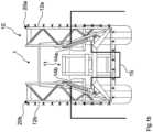
- FIGS 1a to 1c show an agricultural device 1, which is designed as a field sprayer, in rear view.
- the device 1 comprises a distributor rod 10 with a middle part 11.
- the distributor rod 10 also has two booms 12 a, b, which are connected to the middle part 11 by joints.
- Each boom 12 a, b is assigned an adjusting device 14 a, b.
- the adjusting devices 14 a, b are designed as double-acting hydraulic cylinders.
- the adjusting devices 14 a, b can move the respective boom 12 a, b about a respective axis of rotation, wherein the respective axis of rotation is parallel to the direction of travel of the agricultural device 1.
- the adjusting devices 14 a, b are designed such that they can transfer the respective boom 12 a, b from a position completely angled to the device 1, which exists for example during road transport of the device 1, into a completely horizontal position, which exists for example during field work, and vice versa.
- the booms 12 a,b each have several boom sections that are connected to one another via foldable joints.
- the individual boom sections can be folded around a vertical axis so that the working width of the agricultural device can be adjusted.
- the boom sections can be folded independently for the respective boom 12 a,b.
- Figure 1a shows a state in which the booms 12 a,b are fully unfolded.
- Figure 1b shows a state in which only the innermost rod section of the boom 12 a,b is unfolded, while the remaining rod sections are folded in.
- Figure 1c shows a state in which all rod sections of the boom 12 b are unfolded, while only the innermost rod section of the boom 12 a is unfolded.
- the agricultural device 1 further comprises at least one sensor device 20 a,b for each of the booms 12 a,b.
- the sensor device 20 a,b can comprise one or more sensors.
- the sensor device 20 a,b comprises sensors for measuring the vertical acceleration acting on the boom 12 a,b. It can further comprise sensors for measuring a distance of the boom 12 a,b from the ground and/or sensors for determining an angular rotation rate of the boom 12 a,b and/or sensors for determining the folding state of the boom sections of the boom 12 a,b. It should be noted that the sensors do not all have to be attached in the same place.
- a sensor 20 a,b is indicated, which is located approximately in the middle of the unfolded boom 12 a,b. This position is suitable, for example, for measuring the actual vertical acceleration acting on the boom 12 a,b.
- the actuating devices 14 a, b are connected by a hydraulic connecting line 15. It can be seen that the connecting line 15 in the embodiment shown connects the respective piston-side chambers of the hydraulic cylinders 14 a, b to one another.
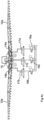
- FIG. 2 shows a detail of the Figure 1 shown field sprayer.
- the hydraulic connections and switching elements are shown schematically. It can be seen that each of the actuating devices 14 a, b is connected to a pressure control valve 16 a, b.
- the pressure control valves 16 a, b are connected to the rod-side chambers of the hydraulic cylinders 14 a, b.
- the connecting line 15 is also connected to a pressure control valve 16 c.
- the pressure control valves 16 a, b, c are connected to the hydraulic lines P and T of a hydraulic circuit.
- T designates the line to a hydraulic tank and P the line to a hydraulic pump.
- a shut-off valve 17 a, b, c is installed between the pressure control valves 16 a, b and the hydraulic cylinders 14 a, b, as well as between the pressure control valve 16 c.
- the pressure control valves 16 a, b, c and the shut-off valves 17 a, b, c are controlled via the control unit 2 (not shown). The respective valves can be controlled individually.
- shut-off valve 17 a, b, c results in no hydraulic fluid flowing from the hydraulic cylinders 14 a, b or the connecting line 15 towards the tank. can flow away. This means that the corresponding hydraulic cylinder 14 a,b cannot move in the corresponding direction. The corresponding boom 12 a,b is thus locked in this direction. If, for example, the shut-off valve 17 a is locked, the hydraulic cylinder 14 a cannot be extended.
- shut-off valves 17 a, b, c are generally open based on measurement data from the sensor device 20 a, b in order to achieve the fastest possible control.
- FIG 3 shows an alternative embodiment of an agricultural device 1'.
- the embodiment shown here has two actuating devices 14 a, b, which are designed as double-acting hydraulic cylinders.
- Pressure control valves 16 a, b and shut-off valves 17 a, b are assigned to the rod-side chambers.
- this embodiment has two further pressure control valves 16 d, e and shut-off valves 17 d, e.
- the respective valves can in turn be controlled individually via a control unit 2.
- Figures 4a to 4c show the states of the booms 12 a,b of the distribution rod 10 with the associated setting states of the pressure control valves 16 a,b,c and shut-off valves 17 a,b,c in different phases of a folding process, here the joint angling of the two booms 12 a,b.
- the control unit 2 controls the corresponding pressure control valve 16 a, b, c in such a way that a respective target pressure prevails in the corresponding cylinder chambers or the hydraulic connecting line.
- the respective target pressure can, for example, be set by the control unit 2 based on preset pressure values for the current folding state.
- the pressure values can For example, they can be stored in a memory of the control unit 2. However, they can also be determined based on sensor measurement data.
- the ring and piston surfaces of the hydraulic cylinder can be taken into account when calculating a target pressure to be set. This is because the hydraulic cylinders 14 a, b have two different sized effective surfaces on the two sides of the piston. The effective surface of the hydraulic cylinder facing the piston rod is smaller than the effective surface facing away from the piston rod. Accordingly, when the forces are in equilibrium, there is a different, in particular greater, pressure on the ring surface than on the piston surface.
- Figure 4b shows the state during bending. It can be seen that the check valves 17 a, b, c are open. As described above, the control unit 2 has set a respective target pressure in the cylinder chambers when the check valves are opened. The pressure in the rod-side chambers of the hydraulic cylinders 14 a, b is then increased to the pressure p2 using the pressure control valves 16 a, b. The pressure p2 can in particular correspond to a target pressure for a desired folding state. By increasing the pressure in the rod-side chambers of the hydraulic cylinders 14 a, b, a force acts on the annular surfaces of the pistons of the hydraulic cylinders 14 a, b.
- Figure 4c shows the state after the bending is completed. It can be seen that all shut-off valves 17 a, b, c are closed again.
- the pressure p2 prevails in the rod-side chambers of the hydraulic cylinders 14 a, b.
- the pressure p3 is generally be equal to the previously prevailing pressure p1. However, it can also be different.
- the two arms 12 a,b were angled equally.
- Figures 5a to 5c show the states of the booms 12 a,b of the distribution rod 10 with the associated setting states of the pressure control valves 16 a,b,c and shut-off valves 17 a,b,c in different phases of a folding process, here the one-sided bending of the boom 12 a.
- the control unit 2 controls the corresponding pressure control valve 16 a, b, c in such a way that a respective target pressure prevails in the corresponding cylinder chambers or the hydraulic connecting line.
- the respective target pressure can be set, for example, by the control unit 2 based on preset pressure values for the current folding state.
- the pressure values can be stored, for example, in a memory of the control unit 2. However, they can also be determined based on sensor measurement data.
- Figure 5b shows the state during the angling of the boom 12 a. It can be seen that the check valves 17 a and 17 c have been opened, but the check valve 17 b is still closed. As described above, the control unit 2 has set a respective target pressure in the cylinder chambers when the check valves were opened. The pressure in the rod-side chamber of the hydraulic cylinder 14 a is then increased to the pressure p2 by means of the pressure control valve 16 a.
- the pressure p2 can, for example, correspond to a desired folding state of the boom 12 a. This exerts a force on the annular surface of the piston of the hydraulic cylinder 14 a.
- Figure 5c shows the state after the angling of the boom 12 a has been completed. It can be seen that all the shut-off valves 17 a, b, c are closed again.
- the set pressure p2 prevails in the rod-side chamber of the hydraulic cylinder 14 a, and the pressure p0 in the hydraulic cylinder 14 b.
- a pressure p3 prevails in the connecting line 15, and thus in the piston-side chambers of the hydraulic cylinders 14 a, b.
- the pressure p3 will generally be the same as the previously prevailing pressure p1. However, it can also be different.
- Figures 6a to 6c show the states of the booms 12 a,b of the distribution rod 10 with the associated setting states of the pressure control valves 16 a,b,c and shut-off valves 17 a,b,c in different phases of a folding process, here the joint tilting of the booms 12 a,b.
- the control unit 2 controls the corresponding pressure control valve 16 a, b, c in such a way that a respective target pressure prevails in the corresponding cylinder chambers or the hydraulic connecting line.
- the respective target pressure can be set, for example, by the control unit 2 based on preset pressure values for the current folding state.
- the pressure values can be stored, for example, in a memory of the control unit 2. However, they can also be determined based on sensor measurement data.
- Figure 6b shows the state during tilting. It can be seen that the shut-off valve 17 c associated with the connecting line 15 is still locked, while the shut-off valve 17 a and the shut-off valve 17 b are open.
- the Control unit 2 sets a respective target pressure in the cylinder chambers when the shut-off valves are opened. Subsequently, the pressure in the rod-side chamber of the hydraulic cylinder 14 a is increased to the pressure p2 a by means of the pressure control valve 16 a, while the pressure in the rod-side chamber of the hydraulic cylinder 14 b is reduced to the pressure p2 b by means of the pressure control valve 16 b.
- the pressure p2 a corresponds to a preset pressure for a folding state in which the boom 12 a is folded relative to the Figure 6a
- the pressure p2 b corresponds to a preset pressure for a folding state in which the boom 12 b is tilted relative to the position shown in Figure 6a shown initial position is angled by an angle alpha.
- Figure 6c shows the state after the tilting of the distributor rod is complete. It can be seen that all shut-off valves 17 a, b, c are closed again.
- the set pressure values p2 a, b prevail in the rod-side chambers of the hydraulic cylinders 14 a, b.
- a pressure p3 prevails in the connecting line 15, and thus in the piston-side chambers of the hydraulic cylinders 14 a, b.
- the pressure p3 will generally be the same as the previously prevailing pressure p1. However, it can also be different.
- Figure 7 shows a schematic of an example of a control circuit with which the position of one of the booms 12 a,b can be controlled. It can be seen that various measurement data serve as input values for the control. The measurement data are recorded, for example, by means of the sensor device 20 a,b.
- the input values include the distance of the boom 12 a,b from the ground, the rotation rate of the boom 12 a,b, and the vertical acceleration of the boom 12 a,b. It should be understood that these examples do not represent an exclusive list. Furthermore, not all of the measured values shown have to be used as input values.
- a common control value is determined from the individual measured values using the respective control parameters k1, k2, k3.
- the values k1, k2, k3 can be simple proportional factors. However, they can also have the form of a PID control.
- the part of the circuit designated "k1" corresponds to a PID control with the measured angular deviation as the input value and a predetermined angular deviation as the setpoint. The same applies to the other input values shown.
- the part relating to the vertical acceleration can have a PID control with the measured vertical acceleration as the input value and either 0 m/s 2 or 9.81 m/s 2 as the setpoint.
- the output values of the parts k1, k2, k3 are each such that they transfer the boom 12 a,b from a measured actual value of the corresponding measured value to a desired target value of the corresponding measured value.
- the output values of the parts k1, k2, k3 are then combined, for example additively. This is done in order to correctly record the overall movement of the boom 12 a,b.
- branch k1 and branch k2 can emit opposite signals: the distance of the boom 12 a,b from the ground is reduced by driving over it, so the corresponding branch k1 will control to raise the boom.
- a positive vertical acceleration i.e. acting away from the ground, acts on the boom 12 a,b.
- Branch k3 will accordingly control to lower the boom.
- the combined signal is equal to 0, i.e., there is no influence on the position of the boom 12 a,b.
- the combined output signal is then combined with a pressure offset that prevails on both sides of the hydraulic cylinder 14 a, b in the rest position.
- the pressure offset takes into account both external forces that are applied to the boom 12 a, b in the desired position and the different effective areas of the two piston sides. Such forces can occur, for example, if the rod is not fully unfolded symmetrically. They can also occur when driving on slopes or curves.
- the pressure offset can vary individually for the respective hydraulic cylinder 14 a, b. The pressure offset should therefore take into account the forces actually applied to the distributor rod 10 in normal operation.
- a control signal is generated for the pressure control valves 16 a, b, c in order to generate pressure values for the chambers of the actuating device 14 a, b. It is possible, as indicated in the figure, that the control signal is limited to a maximum value. This makes it possible, for example, to limit the forces acting on the distributor rod 10 during control.
- control loop shown ensures that the boom 12 a,b is held in a target position or is deflected as little as possible from the target position.
- the described control system can be implemented, for example, in the control unit 2. It should be noted that in general, when the described control system is in operation, the shut-off valves 17 a, b, c are open in order to achieve rapid pressure control in the chambers of the hydraulic cylinders 14 a, b and the connecting line 15. The same applies to the embodiment of the device 1' described with reference to Figure 1.
- the shut-off valves 17 a, b, c generally serve to fix the positions of the pistons of the hydraulic cylinders 14 a, b, and thus the position of the boom when the control system is switched off.
Landscapes
- Life Sciences & Earth Sciences (AREA)
- Engineering & Computer Science (AREA)
- Insects & Arthropods (AREA)
- Pest Control & Pesticides (AREA)
- Wood Science & Technology (AREA)
- Zoology (AREA)
- Environmental Sciences (AREA)
- Catching Or Destruction (AREA)
- Agricultural Machines (AREA)
- Fertilizing (AREA)
Claims (15)
- Appareil agricole (1) pour l'épandage de matériau, tel que de l'engrais, des agents phytosanitaires ou des semences, caractérisé parune rampe de distribution (10) repliable des deux côtés et comportant une partie centrale (11) et deux bras (12 a, b) latéraux reliés à la partie centrale (11) par des articulations ;un premier dispositif de réglage (14 a) hydraulique pour déplacer l'un des bras (12 a) autour d'un premier axe de rotation orienté dans un sens de déplacement de l'appareil agricole (1) ;un second dispositif de réglage (14 b) hydraulique pour déplacer l'autre bras (12 b) autour d'un second axe de rotation orienté dans le sens de déplacement de l'appareil agricole (1) ;une conduite de liaison (15) hydraulique qui relie hydrauliquement le premier dispositif de réglage (14 a) et le second dispositif de réglage (14 b) ; etune unité de régulation (2) ;dans lequel respectivement une soupape de régulation de pression (16 a, b, c) est associée au premier dispositif de réglage (14 a), au second dispositif de réglage (14 b) et à la conduite de liaison (15) ; etdans lequel les soupapes de régulation de pression (16 a, b, c) peuvent être commandées par l'unité de régulation (2).
- Appareil agricole selon la revendication 1, dans lequel respectivement une soupape d'arrêt (17 a, b, c) associée à la soupape de régulation de pression (16 a, b, c) respective est associée au premier dispositif de réglage (14 a), au second dispositif de réglage (14 b) et à la conduite de liaison (15).
- Appareil agricole selon la revendication 1 ou 2, comprenant en outre un dispositif formant capteur (20 a, b) associé à un bras (12 a, b) pour détecter une accélération verticale du bras (12 a, b) respectif, laquelle accélération verticale agit sur le bras (12 a, b) respectif.
- Appareil agricole selon la revendication 3, dans lequel le dispositif formant capteur (20 a, b) est fixé à une distance prédéterminée, en particulier à une distance comprise entre 1 m et 3 m, de l'axe de rotation respectif.
- Appareil agricole selon l'une des revendications 3 ou 4, dans lequel l'unité de régulation (2) est configurée pour commander les soupapes de régulation de pression (16 a, b, c) sur la base de valeurs du dispositif formant capteur (20 a, b).
- Appareil agricole selon l'une des revendications 3 à 5, dans lequel l'unité de régulation (2) est configurée pour commander les soupapes de régulation de pression (16 a, b, c), en particulier au moyen d'un régulateur PID, de sorte qu'une valeur de consigne de l'accélération verticale agit sur le bras (12 a, b) respectif.
- Appareil agricole selon l'une des revendications précédentes, dans lequel le premier et le second dispositif de réglage (14 a, b) sont des vérins hydrauliques double effet.
- Appareil agricole selon la revendication 7, dans lequel la conduite de liaison (15) relie les chambres côté piston du premier et du second dispositif de réglage (14 a, b).
- Appareil agricole selon l'une des revendications précédentes, dans lequel les soupapes de régulation de pression (16 a, b, c) peuvent être commandées indépendamment les unes des autres.
- Appareil agricole selon l'une des revendications précédentes, dans lequel les dispositifs de réglage (14 a, b) respectifs sont aptes à faire passer le bras (12 a, b) respectif d'une position de transport à une position de travail et inversement.
- Procédé permettant la commande d'un appareil agricole selon l'une des revendications précédentes, comprenant les étapes consistant à :régler une première pression de consigne dans une conduite de liaison (15), laquelle relie hydrauliquement un premier dispositif de réglage (14 a) et un second dispositif de réglage (14 b), au moyen de la soupape de régulation de pression (16 c) associée ;régler une deuxième pression de consigne au niveau du premier dispositif de réglage (14 a) au moyen de la soupape de régulation de pression (16 a) associée ; etrégler une troisième pression de consigne au niveau du second dispositif de réglage (14 b) au moyen de la soupape de régulation de pression (16 b) associée.
- Procédé selon la revendication 11, dans lequel la soupape d'arrêt (17 c) associée à la conduite de liaison (15) est fermée après le réglage de la première pression de consigne, et dans lequel le réglage de la deuxième pression de consigne comprend une augmentation de la pression au niveau du premier dispositif de réglage (14 a), et le réglage de la troisième pression de consigne comprend une diminution correspondante de la pression au niveau du second dispositif de réglage (14 b).
- Procédé selon la revendication 12, dans lequel la soupape d'arrêt (17 c) associée à la conduite de liaison (15) reste ouverte après le réglage de la première pression de consigne.
- Procédé selon l'une des revendications 11 à 13, comprenant en outre les étapes consistant àdétecter une accélération verticale d'un bras (12 a, b) ;déterminer une force agissant sur le dispositif de réglage (14 a, b) respectif sur la base de l'accélération verticale détectée ;déterminer des valeurs de pression adaptées pour le dispositif de réglage (14 a, b) respectif et/ou la conduite de liaison (15) ;commander les soupapes de régulation (16 a, b, c) pour le réglage des valeurs de pression adaptées déterminées.
- Procédé selon la revendication 14, dans lequel les valeurs de pression adaptées sont déterminées, en particulier au moyen d'un circuit PID, de sorte qu'une valeur de consigne de l'accélération verticale agit sur le bras (12 a, b).
Priority Applications (1)
| Application Number | Priority Date | Filing Date | Title |
|---|---|---|---|
| EP24193519.6A EP4434339A3 (fr) | 2019-05-27 | 2020-05-19 | Machine de traitement de sol |
Applications Claiming Priority (1)
| Application Number | Priority Date | Filing Date | Title |
|---|---|---|---|
| DE102019114084.6A DE102019114084A1 (de) | 2019-05-27 | 2019-05-27 | Landwirtschaftliches Gerät mit verbesserter Neigungsregelung |
Related Child Applications (1)
| Application Number | Title | Priority Date | Filing Date |
|---|---|---|---|
| EP24193519.6A Division EP4434339A3 (fr) | 2019-05-27 | 2020-05-19 | Machine de traitement de sol |
Publications (2)
| Publication Number | Publication Date |
|---|---|
| EP3753407A1 EP3753407A1 (fr) | 2020-12-23 |
| EP3753407B1 true EP3753407B1 (fr) | 2024-08-14 |
Family
ID=72243061
Family Applications (2)
| Application Number | Title | Priority Date | Filing Date |
|---|---|---|---|
| EP20401029.2A Active EP3753407B1 (fr) | 2019-05-27 | 2020-05-19 | Appareil agricole à réglage de l'inclinaison amélioré |
| EP24193519.6A Pending EP4434339A3 (fr) | 2019-05-27 | 2020-05-19 | Machine de traitement de sol |
Family Applications After (1)
| Application Number | Title | Priority Date | Filing Date |
|---|---|---|---|
| EP24193519.6A Pending EP4434339A3 (fr) | 2019-05-27 | 2020-05-19 | Machine de traitement de sol |
Country Status (4)
| Country | Link |
|---|---|
| EP (2) | EP3753407B1 (fr) |
| DE (1) | DE102019114084A1 (fr) |
| DK (1) | DK3753407T3 (fr) |
| PL (1) | PL3753407T3 (fr) |
Families Citing this family (6)
| Publication number | Priority date | Publication date | Assignee | Title |
|---|---|---|---|---|
| CN113475488B (zh) * | 2021-08-09 | 2024-09-24 | 盐城晟威机械科技有限公司 | 一种挂车式喷杆喷雾机 |
| DE102022100808A1 (de) * | 2022-01-14 | 2023-07-20 | Amazonen-Werke H. Dreyer SE & Co. KG | Landwirtschaftliches Gerät mit verbesserter Neigungsregelung |
| DE102023121069A1 (de) | 2023-08-08 | 2025-02-13 | Voith Patent Gmbh | Hydraulisches Steuerungssystem für ein Spritzgestänge an einer landwirtschaftlichen Feldspritze |
| DE102023121071A1 (de) | 2023-08-08 | 2025-02-13 | Voith Patent Gmbh | Hydraulisches Steuerungssystem für ein Spritzgestänge an einer landwirtschaftlichen Feldspritze |
| DE102023121074A1 (de) | 2023-08-08 | 2025-02-13 | Voith Patent Gmbh | Hydraulisches Steuerungssystem für ein Spritzgestänge an einer landwirtschaftlichen Feldspritze |
| WO2025176665A1 (fr) * | 2024-02-22 | 2025-08-28 | Exel Industries | Véhicule de pulvérisation et procédé de détermination de la progression d'un pliage et d'un dépliage par étapes d'une rampe de pulvérisation agricole avec une pluralité de sections de rampe |
Family Cites Families (7)
| Publication number | Priority date | Publication date | Assignee | Title |
|---|---|---|---|---|
| DE19754930A1 (de) | 1997-12-10 | 1999-06-17 | Amazonen Werke Dreyer H | Landwirtschaftliche Maschine zum Verteilen von Material, vorzugsweise Feldspritze |
| FR2795913A1 (fr) | 1999-07-09 | 2001-01-12 | Michel Barrau | Systeme electronique d'autocontrole du niveau d'inclinaison d'une rampe de pulverisation |
| EP1167095A1 (fr) | 2000-06-26 | 2002-01-02 | K.U. Leuven Research & Development | Procédé et dispositif de commande et de stabilisation d' un mouvement |
| CA2418610C (fr) | 2003-02-10 | 2005-11-15 | Norac Systems International Inc. | Systeme et methode de commande de rotation d'une fleche suspendue |
| DE102015101032A1 (de) * | 2015-01-26 | 2016-07-28 | Amazonen-Werke H. Dreyer Gmbh & Co. Kg | Landwirtschaftliche Maschine und Regelungsverfahren |
| DE102017104814A1 (de) * | 2017-03-08 | 2018-09-13 | Amazonen-Werke H. Dreyer Gmbh & Co. Kg | Steuer- und/oder Regelsystem, landwirtschaftliches Nutzfahrzeug und Verfahren zur Steuerung und/oder Regelung eines landwirtschaftlichen Nutzfahrzeugs |
| DE102017118302A1 (de) * | 2017-08-11 | 2019-02-14 | Amazonen-Werke H. Dreyer Gmbh & Co. Kg | Steuer- und/oder Regelsystem, landwirtschaftliches Nutzfahrzeug und Verfahren zur Steuerung und/oder Regelung eines landwirtschaftlichen Nutzfahrzeuges |
-
2019
- 2019-05-27 DE DE102019114084.6A patent/DE102019114084A1/de active Pending
-
2020
- 2020-05-19 PL PL20401029.2T patent/PL3753407T3/pl unknown
- 2020-05-19 EP EP20401029.2A patent/EP3753407B1/fr active Active
- 2020-05-19 EP EP24193519.6A patent/EP4434339A3/fr active Pending
- 2020-05-19 DK DK20401029.2T patent/DK3753407T3/da active
Also Published As
| Publication number | Publication date |
|---|---|
| EP4434339A2 (fr) | 2024-09-25 |
| DK3753407T3 (da) | 2024-09-16 |
| DE102019114084A1 (de) | 2020-12-03 |
| EP3753407A1 (fr) | 2020-12-23 |
| PL3753407T3 (pl) | 2024-10-21 |
| EP4434339A3 (fr) | 2024-12-18 |
Similar Documents
| Publication | Publication Date | Title |
|---|---|---|
| EP3753407B1 (fr) | Appareil agricole à réglage de l'inclinaison amélioré | |
| DE602004004297T2 (de) | System und Verfahren für die Rollregelung eines aufgehängten Gestänges | |
| EP4212018A1 (fr) | Appareil agricole avec réglage d'inclinaison amélioré | |
| EP3449723B1 (fr) | Système de commande et/ou de réglage, véhicule agricole et procédé de commande et/ou de réglage | |
| WO2021037517A1 (fr) | Engin agricole à suspension améliorée | |
| EP3468340A1 (fr) | Dispositif de régulation, véhicule utilitaire agricole et procédé d'utilisation d'un véhicule utilitaire agricole | |
| EP3592143B1 (fr) | Système de commande et/ou de régulation d'un véhicule utilitaire agricole et procédé de commande et/ou de régulation d'un véhicule utilitaire agricole | |
| DE102015104690A1 (de) | Landwirtschaftliche Maschine und Sicherheitsverfahren | |
| DE102020118528A1 (de) | Landwirtschaftliche Verteilmaschine, vorzugsweise eine Feldspritze oder ein Düngerstreuer | |
| EP3804516B1 (fr) | Machine d'épandage agricole, de préférence pulvérisateur ou distributeur d'engrais | |
| WO2021037519A1 (fr) | Engin agricole à suspension améliorée | |
| EP3791717A1 (fr) | Machine d'épandage agricole, de préférence un pulvérisateur ou distributeur d'engrais | |
| EP3975712B1 (fr) | Système de commande et/ou de régulation destiné à un appareil agricole | |
| EP3975711B1 (fr) | Système de commande et/ou de régulation pour une machine agricole | |
| EP3804515B1 (fr) | Machine d'épandage agricole, de préférence pulvérisateur agricole ou épandeur pneumatique d'engrais | |
| EP3516958B1 (fr) | Appareil de réglage pour un véhicule utilitaire agricole et procédé de fonctionnement du véhicule utilitaire | |
| DE102018103862A1 (de) | Aufhängung für eine landwirtschaftliche Maschine und Verfahren zum Betreiben einer landwirtschaftlichen Maschine | |
| EP3440934A1 (fr) | Système de commande et/ou de réglage, véhicule utilitaire agricole et procédé de commande et/ou de réglage | |
| EP3305071A1 (fr) | Système de commande, véhicule agricole et procédé de commande d'un véhicule agricole | |
| DE202022002936U1 (de) | Landwirtschaftliches Gerät mit verbesserter Neigungsregelung | |
| EP4321021A1 (fr) | Système de commande et/ou de régulation, véhicule utilitaire agricole |
Legal Events
| Date | Code | Title | Description |
|---|---|---|---|
| PUAI | Public reference made under article 153(3) epc to a published international application that has entered the european phase |
Free format text: ORIGINAL CODE: 0009012 |
|
| STAA | Information on the status of an ep patent application or granted ep patent |
Free format text: STATUS: THE APPLICATION HAS BEEN PUBLISHED |
|
| AK | Designated contracting states |
Kind code of ref document: A1 Designated state(s): AL AT BE BG CH CY CZ DE DK EE ES FI FR GB GR HR HU IE IS IT LI LT LU LV MC MK MT NL NO PL PT RO RS SE SI SK SM TR |
|
| AX | Request for extension of the european patent |
Extension state: BA ME |
|
| RAP3 | Party data changed (applicant data changed or rights of an application transferred) |
Owner name: AMAZONEN-WERK H. DREYER SE & CO. KG |
|
| RAP3 | Party data changed (applicant data changed or rights of an application transferred) |
Owner name: AMAZONEN-WERKE H. DREYER SE & CO. KG |
|
| STAA | Information on the status of an ep patent application or granted ep patent |
Free format text: STATUS: REQUEST FOR EXAMINATION WAS MADE |
|
| 17P | Request for examination filed |
Effective date: 20210622 |
|
| RBV | Designated contracting states (corrected) |
Designated state(s): AL AT BE BG CH CY CZ DE DK EE ES FI FR GB GR HR HU IE IS IT LI LT LU LV MC MK MT NL NO PL PT RO RS SE SI SK SM TR |
|
| P01 | Opt-out of the competence of the unified patent court (upc) registered |
Effective date: 20230523 |
|
| GRAP | Despatch of communication of intention to grant a patent |
Free format text: ORIGINAL CODE: EPIDOSNIGR1 |
|
| STAA | Information on the status of an ep patent application or granted ep patent |
Free format text: STATUS: GRANT OF PATENT IS INTENDED |
|
| INTG | Intention to grant announced |
Effective date: 20240318 |
|
| GRAS | Grant fee paid |
Free format text: ORIGINAL CODE: EPIDOSNIGR3 |
|
| GRAA | (expected) grant |
Free format text: ORIGINAL CODE: 0009210 |
|
| STAA | Information on the status of an ep patent application or granted ep patent |
Free format text: STATUS: THE PATENT HAS BEEN GRANTED |
|
| AK | Designated contracting states |
Kind code of ref document: B1 Designated state(s): AL AT BE BG CH CY CZ DE DK EE ES FI FR GB GR HR HU IE IS IT LI LT LU LV MC MK MT NL NO PL PT RO RS SE SI SK SM TR |
|
| REG | Reference to a national code |
Ref country code: GB Ref legal event code: FG4D Free format text: NOT ENGLISH |
|
| REG | Reference to a national code |
Ref country code: CH Ref legal event code: EP |
|
| REG | Reference to a national code |
Ref country code: DE Ref legal event code: R096 Ref document number: 502020008865 Country of ref document: DE |
|
| REG | Reference to a national code |
Ref country code: IE Ref legal event code: FG4D Free format text: LANGUAGE OF EP DOCUMENT: GERMAN |
|
| REG | Reference to a national code |
Ref country code: DK Ref legal event code: T3 Effective date: 20240910 |
|
| REG | Reference to a national code |
Ref country code: NL Ref legal event code: FP |
|
| REG | Reference to a national code |
Ref country code: LT Ref legal event code: MG9D |
|
| PG25 | Lapsed in a contracting state [announced via postgrant information from national office to epo] |
Ref country code: NO Free format text: LAPSE BECAUSE OF FAILURE TO SUBMIT A TRANSLATION OF THE DESCRIPTION OR TO PAY THE FEE WITHIN THE PRESCRIBED TIME-LIMIT Effective date: 20241114 |
|
| PG25 | Lapsed in a contracting state [announced via postgrant information from national office to epo] |
Ref country code: PT Free format text: LAPSE BECAUSE OF FAILURE TO SUBMIT A TRANSLATION OF THE DESCRIPTION OR TO PAY THE FEE WITHIN THE PRESCRIBED TIME-LIMIT Effective date: 20241216 Ref country code: GR Free format text: LAPSE BECAUSE OF FAILURE TO SUBMIT A TRANSLATION OF THE DESCRIPTION OR TO PAY THE FEE WITHIN THE PRESCRIBED TIME-LIMIT Effective date: 20241115 Ref country code: FI Free format text: LAPSE BECAUSE OF FAILURE TO SUBMIT A TRANSLATION OF THE DESCRIPTION OR TO PAY THE FEE WITHIN THE PRESCRIBED TIME-LIMIT Effective date: 20240814 |
|
| PG25 | Lapsed in a contracting state [announced via postgrant information from national office to epo] |
Ref country code: BG Free format text: LAPSE BECAUSE OF FAILURE TO SUBMIT A TRANSLATION OF THE DESCRIPTION OR TO PAY THE FEE WITHIN THE PRESCRIBED TIME-LIMIT Effective date: 20240814 |
|
| PG25 | Lapsed in a contracting state [announced via postgrant information from national office to epo] |
Ref country code: LV Free format text: LAPSE BECAUSE OF FAILURE TO SUBMIT A TRANSLATION OF THE DESCRIPTION OR TO PAY THE FEE WITHIN THE PRESCRIBED TIME-LIMIT Effective date: 20240814 |
|
| PG25 | Lapsed in a contracting state [announced via postgrant information from national office to epo] |
Ref country code: IS Free format text: LAPSE BECAUSE OF FAILURE TO SUBMIT A TRANSLATION OF THE DESCRIPTION OR TO PAY THE FEE WITHIN THE PRESCRIBED TIME-LIMIT Effective date: 20241214 |
|
| PG25 | Lapsed in a contracting state [announced via postgrant information from national office to epo] |
Ref country code: HR Free format text: LAPSE BECAUSE OF FAILURE TO SUBMIT A TRANSLATION OF THE DESCRIPTION OR TO PAY THE FEE WITHIN THE PRESCRIBED TIME-LIMIT Effective date: 20240814 |
|
| PG25 | Lapsed in a contracting state [announced via postgrant information from national office to epo] |
Ref country code: ES Free format text: LAPSE BECAUSE OF FAILURE TO SUBMIT A TRANSLATION OF THE DESCRIPTION OR TO PAY THE FEE WITHIN THE PRESCRIBED TIME-LIMIT Effective date: 20240814 Ref country code: RS Free format text: LAPSE BECAUSE OF FAILURE TO SUBMIT A TRANSLATION OF THE DESCRIPTION OR TO PAY THE FEE WITHIN THE PRESCRIBED TIME-LIMIT Effective date: 20241114 |
|
| PG25 | Lapsed in a contracting state [announced via postgrant information from national office to epo] |
Ref country code: RS Free format text: LAPSE BECAUSE OF FAILURE TO SUBMIT A TRANSLATION OF THE DESCRIPTION OR TO PAY THE FEE WITHIN THE PRESCRIBED TIME-LIMIT Effective date: 20241114 Ref country code: PT Free format text: LAPSE BECAUSE OF FAILURE TO SUBMIT A TRANSLATION OF THE DESCRIPTION OR TO PAY THE FEE WITHIN THE PRESCRIBED TIME-LIMIT Effective date: 20241216 Ref country code: NO Free format text: LAPSE BECAUSE OF FAILURE TO SUBMIT A TRANSLATION OF THE DESCRIPTION OR TO PAY THE FEE WITHIN THE PRESCRIBED TIME-LIMIT Effective date: 20241114 Ref country code: LV Free format text: LAPSE BECAUSE OF FAILURE TO SUBMIT A TRANSLATION OF THE DESCRIPTION OR TO PAY THE FEE WITHIN THE PRESCRIBED TIME-LIMIT Effective date: 20240814 Ref country code: IS Free format text: LAPSE BECAUSE OF FAILURE TO SUBMIT A TRANSLATION OF THE DESCRIPTION OR TO PAY THE FEE WITHIN THE PRESCRIBED TIME-LIMIT Effective date: 20241214 Ref country code: HR Free format text: LAPSE BECAUSE OF FAILURE TO SUBMIT A TRANSLATION OF THE DESCRIPTION OR TO PAY THE FEE WITHIN THE PRESCRIBED TIME-LIMIT Effective date: 20240814 Ref country code: GR Free format text: LAPSE BECAUSE OF FAILURE TO SUBMIT A TRANSLATION OF THE DESCRIPTION OR TO PAY THE FEE WITHIN THE PRESCRIBED TIME-LIMIT Effective date: 20241115 Ref country code: FI Free format text: LAPSE BECAUSE OF FAILURE TO SUBMIT A TRANSLATION OF THE DESCRIPTION OR TO PAY THE FEE WITHIN THE PRESCRIBED TIME-LIMIT Effective date: 20240814 Ref country code: ES Free format text: LAPSE BECAUSE OF FAILURE TO SUBMIT A TRANSLATION OF THE DESCRIPTION OR TO PAY THE FEE WITHIN THE PRESCRIBED TIME-LIMIT Effective date: 20240814 Ref country code: BG Free format text: LAPSE BECAUSE OF FAILURE TO SUBMIT A TRANSLATION OF THE DESCRIPTION OR TO PAY THE FEE WITHIN THE PRESCRIBED TIME-LIMIT Effective date: 20240814 |
|
| PG25 | Lapsed in a contracting state [announced via postgrant information from national office to epo] |
Ref country code: SM Free format text: LAPSE BECAUSE OF FAILURE TO SUBMIT A TRANSLATION OF THE DESCRIPTION OR TO PAY THE FEE WITHIN THE PRESCRIBED TIME-LIMIT Effective date: 20240814 Ref country code: RO Free format text: LAPSE BECAUSE OF FAILURE TO SUBMIT A TRANSLATION OF THE DESCRIPTION OR TO PAY THE FEE WITHIN THE PRESCRIBED TIME-LIMIT Effective date: 20240814 |
|
| PGFP | Annual fee paid to national office [announced via postgrant information from national office to epo] |
Ref country code: NL Payment date: 20250317 Year of fee payment: 6 |
|
| PG25 | Lapsed in a contracting state [announced via postgrant information from national office to epo] |
Ref country code: EE Free format text: LAPSE BECAUSE OF FAILURE TO SUBMIT A TRANSLATION OF THE DESCRIPTION OR TO PAY THE FEE WITHIN THE PRESCRIBED TIME-LIMIT Effective date: 20240814 |
|
| PG25 | Lapsed in a contracting state [announced via postgrant information from national office to epo] |
Ref country code: CZ Free format text: LAPSE BECAUSE OF FAILURE TO SUBMIT A TRANSLATION OF THE DESCRIPTION OR TO PAY THE FEE WITHIN THE PRESCRIBED TIME-LIMIT Effective date: 20240814 |
|
| PG25 | Lapsed in a contracting state [announced via postgrant information from national office to epo] |
Ref country code: SK Free format text: LAPSE BECAUSE OF FAILURE TO SUBMIT A TRANSLATION OF THE DESCRIPTION OR TO PAY THE FEE WITHIN THE PRESCRIBED TIME-LIMIT Effective date: 20240814 |
|
| REG | Reference to a national code |
Ref country code: DE Ref legal event code: R097 Ref document number: 502020008865 Country of ref document: DE |
|
| PLBE | No opposition filed within time limit |
Free format text: ORIGINAL CODE: 0009261 |
|
| STAA | Information on the status of an ep patent application or granted ep patent |
Free format text: STATUS: NO OPPOSITION FILED WITHIN TIME LIMIT |
|
| PGFP | Annual fee paid to national office [announced via postgrant information from national office to epo] |
Ref country code: DE Payment date: 20250325 Year of fee payment: 6 Ref country code: PL Payment date: 20250314 Year of fee payment: 6 |
|
| PGFP | Annual fee paid to national office [announced via postgrant information from national office to epo] |
Ref country code: DK Payment date: 20250516 Year of fee payment: 6 |
|
| PGFP | Annual fee paid to national office [announced via postgrant information from national office to epo] |
Ref country code: IT Payment date: 20250422 Year of fee payment: 6 |
|
| 26N | No opposition filed |
Effective date: 20250515 |
|
| PG25 | Lapsed in a contracting state [announced via postgrant information from national office to epo] |
Ref country code: SE Free format text: LAPSE BECAUSE OF FAILURE TO SUBMIT A TRANSLATION OF THE DESCRIPTION OR TO PAY THE FEE WITHIN THE PRESCRIBED TIME-LIMIT Effective date: 20240814 |
|
| REG | Reference to a national code |
Ref country code: CH Ref legal event code: H13 Free format text: ST27 STATUS EVENT CODE: U-0-0-H10-H13 (AS PROVIDED BY THE NATIONAL OFFICE) Effective date: 20251223 |
|
| PG25 | Lapsed in a contracting state [announced via postgrant information from national office to epo] |
Ref country code: LU Free format text: LAPSE BECAUSE OF NON-PAYMENT OF DUE FEES Effective date: 20250519 |
|
| PG25 | Lapsed in a contracting state [announced via postgrant information from national office to epo] |
Ref country code: CH Free format text: LAPSE BECAUSE OF NON-PAYMENT OF DUE FEES Effective date: 20250531 |
|
| GBPC | Gb: european patent ceased through non-payment of renewal fee |
Effective date: 20250519 |
|
| REG | Reference to a national code |
Ref country code: BE Ref legal event code: MM Effective date: 20250531 |
|
| PG25 | Lapsed in a contracting state [announced via postgrant information from national office to epo] |
Ref country code: MC Free format text: LAPSE BECAUSE OF FAILURE TO SUBMIT A TRANSLATION OF THE DESCRIPTION OR TO PAY THE FEE WITHIN THE PRESCRIBED TIME-LIMIT Effective date: 20240814 |
|
| PG25 | Lapsed in a contracting state [announced via postgrant information from national office to epo] |
Ref country code: GB Free format text: LAPSE BECAUSE OF NON-PAYMENT OF DUE FEES Effective date: 20250519 |
|
| PG25 | Lapsed in a contracting state [announced via postgrant information from national office to epo] |
Ref country code: IE Free format text: LAPSE BECAUSE OF NON-PAYMENT OF DUE FEES Effective date: 20250519 |
|
| PG25 | Lapsed in a contracting state [announced via postgrant information from national office to epo] |
Ref country code: BE Free format text: LAPSE BECAUSE OF NON-PAYMENT OF DUE FEES Effective date: 20250531 |
|
| PGFP | Annual fee paid to national office [announced via postgrant information from national office to epo] |
Ref country code: FR Payment date: 20260309 Year of fee payment: 7 |