EP3753740B1 - Bilderzeugungsvorrichtung und verfahren zur steuerung der bilderzeugungsvorrichtung - Google Patents
Bilderzeugungsvorrichtung und verfahren zur steuerung der bilderzeugungsvorrichtung Download PDFInfo
- Publication number
- EP3753740B1 EP3753740B1 EP20179624.0A EP20179624A EP3753740B1 EP 3753740 B1 EP3753740 B1 EP 3753740B1 EP 20179624 A EP20179624 A EP 20179624A EP 3753740 B1 EP3753740 B1 EP 3753740B1
- Authority
- EP
- European Patent Office
- Prior art keywords
- sheet
- main scanning
- controller
- scanning direction
- paper sheet
- Prior art date
- Legal status (The legal status is an assumption and is not a legal conclusion. Google has not performed a legal analysis and makes no representation as to the accuracy of the status listed.)
- Active
Links
Images


Classifications
-
- B—PERFORMING OPERATIONS; TRANSPORTING
- B41—PRINTING; LINING MACHINES; TYPEWRITERS; STAMPS
- B41J—TYPEWRITERS; SELECTIVE PRINTING MECHANISMS, i.e. MECHANISMS PRINTING OTHERWISE THAN FROM A FORME; CORRECTION OF TYPOGRAPHICAL ERRORS
- B41J11/00—Devices or arrangements of selective printing mechanisms, e.g. ink-jet printers or thermal printers, for supporting or handling copy material in sheet or web form
- B41J11/0025—Handling copy materials differing in width
- B41J11/003—Paper-size detection, i.e. automatic detection of the length and/or width of copy material
-
- H—ELECTRICITY
- H04—ELECTRIC COMMUNICATION TECHNIQUE
- H04N—PICTORIAL COMMUNICATION, e.g. TELEVISION
- H04N1/00—Scanning, transmission or reproduction of documents or the like, e.g. facsimile transmission; Details thereof
- H04N1/00567—Handling of original or reproduction media, e.g. cutting, separating, stacking
- H04N1/0057—Conveying sheets before or after scanning
- H04N1/00599—Using specific components
-
- B—PERFORMING OPERATIONS; TRANSPORTING
- B41—PRINTING; LINING MACHINES; TYPEWRITERS; STAMPS
- B41J—TYPEWRITERS; SELECTIVE PRINTING MECHANISMS, i.e. MECHANISMS PRINTING OTHERWISE THAN FROM A FORME; CORRECTION OF TYPOGRAPHICAL ERRORS
- B41J2/00—Typewriters or selective printing mechanisms characterised by the printing or marking process for which they are designed
- B41J2/005—Typewriters or selective printing mechanisms characterised by the printing or marking process for which they are designed characterised by bringing liquid or particles selectively into contact with a printing material
- B41J2/01—Ink jet
- B41J2/015—Ink jet characterised by the jet generation process
- B41J2/04—Ink jet characterised by the jet generation process generating single droplets or particles on demand
- B41J2/045—Ink jet characterised by the jet generation process generating single droplets or particles on demand by pressure, e.g. electromechanical transducers
- B41J2/04501—Control methods or devices therefor, e.g. driver circuits, control circuits
- B41J2/04505—Control methods or devices therefor, e.g. driver circuits, control circuits aiming at correcting alignment
-
- B—PERFORMING OPERATIONS; TRANSPORTING
- B41—PRINTING; LINING MACHINES; TYPEWRITERS; STAMPS
- B41J—TYPEWRITERS; SELECTIVE PRINTING MECHANISMS, i.e. MECHANISMS PRINTING OTHERWISE THAN FROM A FORME; CORRECTION OF TYPOGRAPHICAL ERRORS
- B41J11/00—Devices or arrangements of selective printing mechanisms, e.g. ink-jet printers or thermal printers, for supporting or handling copy material in sheet or web form
- B41J11/008—Controlling printhead for accurately positioning print image on printing material, e.g. with the intention to control the width of margins
-
- B—PERFORMING OPERATIONS; TRANSPORTING
- B41—PRINTING; LINING MACHINES; TYPEWRITERS; STAMPS
- B41J—TYPEWRITERS; SELECTIVE PRINTING MECHANISMS, i.e. MECHANISMS PRINTING OTHERWISE THAN FROM A FORME; CORRECTION OF TYPOGRAPHICAL ERRORS
- B41J2/00—Typewriters or selective printing mechanisms characterised by the printing or marking process for which they are designed
- B41J2/005—Typewriters or selective printing mechanisms characterised by the printing or marking process for which they are designed characterised by bringing liquid or particles selectively into contact with a printing material
- B41J2/01—Ink jet
- B41J2/015—Ink jet characterised by the jet generation process
- B41J2/04—Ink jet characterised by the jet generation process generating single droplets or particles on demand
- B41J2/045—Ink jet characterised by the jet generation process generating single droplets or particles on demand by pressure, e.g. electromechanical transducers
- B41J2/04501—Control methods or devices therefor, e.g. driver circuits, control circuits
- B41J2/04586—Control methods or devices therefor, e.g. driver circuits, control circuits controlling heads of a type not covered by groups B41J2/04575 - B41J2/04585, or of an undefined type
-
- B—PERFORMING OPERATIONS; TRANSPORTING
- B41—PRINTING; LINING MACHINES; TYPEWRITERS; STAMPS
- B41J—TYPEWRITERS; SELECTIVE PRINTING MECHANISMS, i.e. MECHANISMS PRINTING OTHERWISE THAN FROM A FORME; CORRECTION OF TYPOGRAPHICAL ERRORS
- B41J2/00—Typewriters or selective printing mechanisms characterised by the printing or marking process for which they are designed
- B41J2/005—Typewriters or selective printing mechanisms characterised by the printing or marking process for which they are designed characterised by bringing liquid or particles selectively into contact with a printing material
- B41J2/01—Ink jet
- B41J2/135—Nozzles
- B41J2/145—Arrangement thereof
- B41J2/155—Arrangement thereof for line printing
-
- H—ELECTRICITY
- H04—ELECTRIC COMMUNICATION TECHNIQUE
- H04N—PICTORIAL COMMUNICATION, e.g. TELEVISION
- H04N1/00—Scanning, transmission or reproduction of documents or the like, e.g. facsimile transmission; Details thereof
- H04N1/00567—Handling of original or reproduction media, e.g. cutting, separating, stacking
- H04N1/0066—Aligning or positioning related to handling
-
- H—ELECTRICITY
- H04—ELECTRIC COMMUNICATION TECHNIQUE
- H04N—PICTORIAL COMMUNICATION, e.g. TELEVISION
- H04N1/00—Scanning, transmission or reproduction of documents or the like, e.g. facsimile transmission; Details thereof
- H04N1/00681—Detecting the presence, position or size of a sheet or correcting its position before scanning
- H04N1/00684—Object of the detection
- H04N1/00687—Presence or absence
-
- H—ELECTRICITY
- H04—ELECTRIC COMMUNICATION TECHNIQUE
- H04N—PICTORIAL COMMUNICATION, e.g. TELEVISION
- H04N1/00—Scanning, transmission or reproduction of documents or the like, e.g. facsimile transmission; Details thereof
- H04N1/00681—Detecting the presence, position or size of a sheet or correcting its position before scanning
- H04N1/00785—Correcting the position of a sheet before scanning
-
- H—ELECTRICITY
- H04—ELECTRIC COMMUNICATION TECHNIQUE
- H04N—PICTORIAL COMMUNICATION, e.g. TELEVISION
- H04N1/00—Scanning, transmission or reproduction of documents or the like, e.g. facsimile transmission; Details thereof
- H04N1/024—Details of scanning heads ; Means for illuminating the original
- H04N1/028—Details of scanning heads ; Means for illuminating the original for picture information pick-up
Definitions
- the present disclosure relates to an image forming apparatus that reads a paper sheet conveyed for printing.
- An apparatus that reads a paper sheet using an image sensor.
- an image forming apparatus such as a multifunction peripheral or a printer.
- Image data is generated based on an analog image signal output from an image sensor.
- the image sensor may be used for obtaining information about the paper sheet.
- a following device that uses an image sensor for detecting a size of a paper sheet.
- a following document reader device A set document is automatically conveyed.
- a read unit including a plurality of photoelectric conversion elements arranged in a main scanning direction reads a first area of the conveyed document, and reads a second area different from the first area.
- the device includes an edge guide that is slidable so as to guide an edge of the automatically conveyed document in a conveying direction, an interlocking mechanism that mechanically interlocks with sliding of the edge guide, and a displacement member that is attached to the interlocking mechanism and moves along with interlocking of the interlocking mechanism so as to change its position on the second area.
- the device stores a correspondence between size information and output patterns of the plurality of elements for each document size, and determines a size of the document based on output patterns of the plurality of elements obtained by reading the second area and the correspondence. Thus, a size of the document is determined.
- a position of the conveyed paper sheet (the paper sheet used for printing) in the main scanning direction may be deviated from an ideal position.
- the image sensor reads the conveyed paper sheet. On the basis of a result of reading, an edge of the paper sheet (a position of a side edge) is detected, so that a degree of the deviation can be determined. For instance, on the basis of a result of detection, it is possible to prevent ink ejection to a part where the paper sheet does not exist.
- the image sensor When reading the conveyed paper sheet, conventionally, the image sensor is used, which has a reading width in the main scanning direction larger than a main scanning direction width of the paper sheet of a largest printable size. In other words, conventionally, the image sensor that reads the entire area of the paper sheet of the largest size is used. In this way, it is possible to recognize both end edge positions of the conveyed paper sheet of any size.
- the image sensor is more expensive.
- a common image sensor available in the market may be smaller in the length, and a custom-made sensor may be necessary.
- it is necessary to use an expensive image sensor having a large reading width which causes a problem that a production cost of the image forming apparatus is increased.
- An image forming apparatus includes a sheet feeder, a sheet conveyor, a line head, an image sensor, a moving mechanism, and a controller.
- the sheet feeder feeds a paper sheet.
- the sheet conveyor conveys the paper sheet fed from the sheet feeder.
- the line head includes a plurality of nozzles aligned in a main scanning direction perpendicular to a sheet conveying direction.
- the line head ejects ink for printing from the nozzles to the conveyed paper sheet.
- the image sensor is disposed on an upstream side of the line head in the main scanning direction.
- the image sensor reads the conveyed paper sheet in the main scanning direction.
- the image sensor has a reading width in the main scanning direction, smaller than main scanning direction widths of some paper sheets out of printable size paper sheets.
- the moving mechanism includes a moving motor.
- the moving mechanism moves the image sensor in the main scanning direction.
- the controller controls the moving mechanism to move the image sensor from a predetermined reference position toward one side in the main scanning direction, so that an edge on the one side out of edges of the large width sheet can be read.
- the controller recognizes a deviation direction and a deviation amount of a position of the conveyed large width sheet in the main scanning direction.
- a method for controlling an image forming apparatus includes: feeding a paper sheet; conveying the fed paper sheet; using a line head including a plurality of nozzles aligned in a main scanning direction perpendicular to a sheet conveying direction, so as to print by ejecting ink from the nozzles to the conveyed paper sheet; disposing an image sensor on an upstream side of the line head in the sheet conveying direction; using the image sensor to read the conveyed paper sheet in the main scanning direction; setting a reading width of the image sensor in the main scanning direction smaller than main scanning direction widths of some paper sheets out of printable size paper sheets; moving the image sensor in the main scanning direction; moving the image sensor from a predetermined reference position toward one side in the main scanning direction, so that an edge on the one side out of edges of the large width sheet can be read, in setting for using a large width sheet having a main scanning direction width larger than the reading width; and recognizing a deviation direction and a deviation amount of a position of the conveyed large width sheet
- the present disclosure enables to precisely recognize position deviation of a paper sheet in a main scanning direction even using an inexpensive image sensor having a small reading width.
- An image forming apparatus 100 performs printing using ink.
- a printer is exemplified and described as the image forming apparatus 100.
- the image forming apparatus 100 may also be a multifunction peripheral, for example.
- the image forming apparatus 100 includes a sheet feeder 100a, a main body apparatus 100b, a first post processing apparatus 100c, and a second post processing apparatus 100d.
- a solid line arrow indicates a sheet conveying direction.
- the sheet feeder 100a and the main body apparatus 100b are coupled (connected) to each other.
- the main body apparatus 100b and the first post processing apparatus 100c are coupled (connected) to each other.
- the first post processing apparatus 100c and the second post processing apparatus 100d are coupled (connected) to each other.
- the sheet feeder 100a includes a plurality of sheet feed cassettes 101. Each of the sheet feed cassettes 101 stores paper sheets. When printing is performed, a paper sheet is fed from one of the sheet feed cassettes 101. One sheet feed roller is provided to one sheet feed cassette 101. When printing is performed, the sheet feed roller for feeding the paper sheet of the sheet feed cassette 101 rotates. The sheet feeder 100a conveys the fed paper sheet toward the main body apparatus 100b.
- the main body apparatus 100b performs printing on the paper sheet.
- the main body apparatus 100b performs printing using ink.
- the first post processing apparatus 100c is an apparatus for performing drying of the paper sheet and decurling (removing curling) of the same.
- the first post processing apparatus 100c includes a fan 102 and a heater 103.
- the fan 102 blows air to the paper sheet printed by the main body apparatus 100b.
- the heater 103 heats air blown to the paper sheet. In this way, ink can be dried.
- the first post processing apparatus 100c includes a decurl roller pair 104.
- the decurl roller pair 104 applies pressure to the paper sheet.
- the second post processing apparatus 100d discharges the paper sheet onto a discharge tray 105.
- the second post processing apparatus 100d can reverse front and back sides of the paper sheet so that the printed side faces down.
- the image forming apparatus 100 includes a controller 1, a storage medium 2, an operation panel 3, a printing unit 4, and a communication circuit 5.
- the controller 1, the storage medium 2, the operation panel 3, and the communication circuit 5 are disposed in the main body apparatus 100b.
- the controller 1 controls individual units of the image forming apparatus 100.
- the controller 1 is a circuit board including a control circuit 10, an image processing circuit 11, and an image data generation circuit 12.
- the control circuit 10 is a CPU.
- the control circuit 10 performs calculation and processing based on a control program and control data stored in the storage medium 2.
- the image forming apparatus 100 includes a nonvolatile storage device such as a ROM and a storage (an HDD or a flash ROM), as the storage medium 2. Further, the image forming apparatus 100 includes a volatile storage device such as a RAM, as the storage medium 2.
- the image processing circuit 11 performs image processing of image data to be used for printing.
- the image processing circuit 11 generates ink ejection image data 90.
- the operation panel 3 includes a display panel 31 and a touch panel 32.
- the controller 1 controls the display panel 31 to display setting screens and information.
- the display panel 31 displays operation images such as keys, buttons, and tabs.
- the touch panel 32 detects a touch operation on the display panel 31. On the basis of an output of the touch panel 32, the controller 1 recognizes an operation image that is operated.
- the controller 1 recognizes a setting operation made by a user.
- the printing unit 4 includes the sheet feeder 100a, a part of the main body apparatus 100b, the first post processing apparatus 100c, and the second post processing apparatus 100d.
- the main body apparatus 100b includes a sheet conveyor 4a and an image former 4b as the printing unit 4.
- the controller 1 controls an operation of the printing unit 4.
- the operation panel 3 receives selection of the sheet feed cassette 101 to be used for printing.
- the controller 1 rotates the sheet feed roller of the selected sheet feed cassette 101. Further, the controller 1 allows the paper sheet to enter the sheet conveyor 4a of the main body apparatus 100b.
- the sheet conveyor 4a conveys the paper sheet toward the image former 4b.
- a reader 6 in a conveying path of the sheet conveyor 4a, there are disposed a reader 6, a registration sensor 43, a registration roller pair 41, and a head 49 in order from an upstream side in the sheet conveying direction.
- a registration motor 42 is disposed for rotating the registration roller pair 41.
- the controller 1 controls rotation of the registration motor 42 so as to control rotation of the registration roller pair 41.
- the main body apparatus 100b includes a registration sensor 43.
- the registration sensor 43 is disposed on the upstream side of the registration roller pair 41 in the sheet conveying direction.
- An output level of the registration sensor 43 varies depending on whether the paper sheet is detected or not.
- An output of the registration sensor 43 is input to the controller 1.
- the controller 1 recognizes that a front end of the paper sheet has reached the registration sensor 43. Further, the controller 1 recognizes that a rear end of the paper sheet has passed the registration sensor 43.
- the controller 1 keeps the registration roller pair 41 stopped. For instance, when the rear end of the previous paper sheet passes the registration sensor 43, the controller 1 stops the registration roller pair 41. On the other hand, the controller 1 rotates a conveying roller pair 44 next to and on the upstream side of the registration roller pair 41. The front end of the paper sheet abuts against the registration roller pair 41. The abutting paper sheet bends, and the front end of the paper sheet abuts against a nip of the registration roller pair 41. A skew of the paper sheet is corrected.
- the controller 1 After recognizing that the front end of the paper sheet has reached on the basis of the output of the registration sensor 43, when a predetermined bending formation time elapses, the controller 1 rotates the registration roller pair 41. In this way, the paper sheet is sent out to a conveyor belt 45.
- the conveyor belt 45 is stretched around a drive roller 46 and a driven roller 47.
- a belt motor 48 is provided for rotating the drive roller 46.
- the controller 1 controls the belt motor 48 to rotate, so that the conveyor belt 45 circulates.
- the conveyor belt 45 sucks the paper sheet.
- a plurality of through holes are formed in the conveyor belt 45.
- a sucking device is disposed for sucking air through the through holes. A position of the paper sheet during printing can be fixed by the sucking operation.
- the image former 4b performs printing on the conveyed paper sheet.
- the image former 4b ejects ink to the conveyed paper sheet so as to record an image.
- the image former 4b includes four line heads 49.
- the line heads 49 one head ejects black ink, another head ejects yellow ink, another head ejects cyan ink, and another head ejects magenta ink.
- the line heads 49 are secured.
- the line heads 49 are disposed above the conveyor belt 45. A certain gap is formed between the conveyor belt 45 and the line heads 49. The paper sheet passes through this gap.
- the line head 49 includes a plurality of nozzles.
- the nozzles are aligned in a direction perpendicular to the sheet conveying direction (in the main scanning direction) (in the direction perpendicular to the paper of FIG 1 ).
- An opening of each nozzle faces the conveyor belt 45.
- the controller 1 supplies ink ejection image data 90 for printing to the line head 49.
- the line head 49 ejects ink from the nozzles to the conveyed paper sheet.
- the ink lands on the conveyed paper sheet. In this way, an image is recorded (formed).
- a sheet sensor 410 is disposed on the upstream side of the line head 49.
- the sheet sensor 410 detects reaching of the front end of the paper sheet and passing of the rear end of the same.
- the sheet sensor 410 is a sensor for determining a timing of starting to print a page.
- An output of the sheet sensor 410 is input to the controller 1.
- the controller 1 recognizes that the front end of the paper sheet has reached the sheet sensor 410.
- the controller 1 controls the line heads 49 to start ink ejection (drawing) of a first line.
- the wait time is determined for each line head 49. For instance, the wait time is a time obtained by dividing a distance between a paper sheet detection position of the sheet sensor 410 and the nozzle of the line head 49 by a sheet conveying speed in the specification.
- the controller 1 is connected to the communication circuit 5.
- the communication circuit 5 includes a communication connector, a communication control circuit, and a communication memory.
- the communication memory stores communication software.
- the communication circuit 5 communicates with a computer 200.
- the computer 200 is a PC or a server.
- the controller 1 receives print data from the computer 200.
- the print data includes print setting and print content.
- the print data includes data described in a page description language.
- the controller 1 (the image processing circuit 11) analyzes the received (input) print data. On the basis of the received print data, the controller 1 generates image data (raster data).
- the reader 6 is disposed on the upstream side of the most upstream line head 49, the registration roller pair 41, and the registration sensor 43 in the sheet conveying direction.
- FIG 1 illustrates an example in which the reader 6 (an image sensor 61) is disposed between the conveying roller pair 44 and the registration sensor 43.
- the reader 6 reads the conveyed paper sheet.
- the reader 6 includes the image sensor 61 for reading.
- the image sensor 61 is a line sensor.
- the image sensor 61 includes a plurality of light receiving elements.
- the plurality of light receiving elements are aligned in the main scanning direction (the direction perpendicular to the paper of FIG 3 ).
- the image sensor 61 reads the conveyed paper sheet in the main scanning direction.
- the controller 1 controls the image sensor 61 to repeat reading in the main scanning direction. For instance, reading resolution of the image sensor 61 is the same as printing resolution of the line head 49.
- a sheet conveying path 412 is constituted of a conveyor guide 411.
- the reader 6 is disposed below the sheet conveying path 412.
- a lamp 60 is disposed at a position facing an upper surface of the reader 6.
- the lamp 60 emits light along the main scanning direction.
- the lamp 60 emits light toward the sheet conveying path 412 and the upper surface of the reader 6 (in a downward direction in FIG 3 ).
- the lamp 60 emits light so that the light passes across the sheet conveying path 412 in the up and down direction.
- the conveyed paper sheet blocks an optical path of the lamp 60.
- the upper surface of the reader 6 transmits the light.
- the upper surface of the reader 6 is a glass plate or a transparent resin plate.
- a lens 62 (rod lens array) and the image sensor 61 are disposed in the reader 6. The light from the lamp 60 passes through the lens 62 and enters the image sensor 61.
- the reader 6 is a CIS type reader 6.
- the image sensor 61 outputs charges accumulated in the light receiving elements as an analog image signal i1.
- the image sensor 61 outputs the analog image signal i1 every time when reading one line.
- the output of the image sensor 61 is input to the controller 1 (the image data generation circuit 12).
- the image data generation circuit 12 performs A/D conversion of the analog image signal i1 and generates read image data 7.
- the image data generation circuit 12 repeats the generation of the read image data 7 by line.
- the controller 1 controls the storage medium 2 to store the generated read image data 7.
- the read image data 7 outputs dark (black or high density) pixel values for pixels obtained by reading the paper sheet (pixels in a part where the paper sheet exists). On the contrary, it outputs light (white or low density) pixel values for pixels in a part where the paper sheet does not exist.
- the controller 1 can recognize a position of an edge Eg (side edge) of the conveyed paper sheet in the main scanning direction.
- the image forming apparatus 100 includes a moving mechanism 8.
- the moving mechanism 8 moves the image sensor 61 in the main scanning direction.
- the moving mechanism 8 includes a moving motor 81 as a drive source for moving the image sensor 61.
- the moving motor 81 can rotate in both forward and reverse directions.
- the moving mechanism 8 includes a slide table 82 and a slide guide 83.
- the slide guide 83 has a U-shaped cross section.
- the slide guide 83 guides movement of the slide table 82.
- the reader 6 is secured to the slide table 82. A lower surface of the reader 6 and an upper surface of the slide table 82 contact with each other.
- the slide table 82 moves in the main scanning direction.
- the slide table 82 includes a nut 84.
- a ball screw 85 is inserted through the nut 84. Note that the ball screw 85 is not shown in FIG 3 .
- the moving motor 81 rotates the ball screw 85.
- the controller 1 controls the moving motor 81 to rotate.
- the ball screw 85 rotates, and the reader 6 moves together with the slide table 82.
- the rotation of the moving motor 81 is converted into a linear movement in one axis (in the main scanning direction).
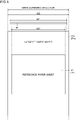
- the largest rectangle indicates the paper sheet of a largest size that can be printed by the image forming apparatus 100.
- the paper sheet of a largest size that can be printed by the image forming apparatus 100 is referred to as a largest paper sheet Pm.
- the largest paper sheet Pm is determined in advance.
- the largest paper sheet Pm is SRA3.
- the SRA3 size is larger than the A3 size.
- a long side of the SRA3 is 450 mm, and a short side thereof is 320 mm.
- the SRA3 size paper sheet is a paper sheet in consideration of cutting off its sides after printing so as to make the A3 size.
- the SRA3 size paper sheet is used for obtaining a printed matter of the A3 size with border-free printing.
- the reading width W1 of the image sensor 61 in the main scanning direction is smaller than a width W2 of the short side of the largest paper sheet Pm. Further, the reading width W1 of the image sensor 61 in the main scanning direction is larger than a width W3 of the long side of a predetermined reference paper sheet Pr.
- a size of the reference paper sheet Pr can be determined based on the paper sheet of a frequently used size. For instance, the size of the reference paper sheet Pr is the A4 size. The size of the reference paper sheet Pr may be a letter size. FIG 5 illustrates an example in which the A4 size sheet is the reference paper sheet Pr.
- the both edges Eg in the main scanning direction can be read for the reference paper sheet Pr and for a paper sheet smaller than the reference paper sheet Pr.
- the reading width W1 of the image sensor 61 in the main scanning direction is smaller than the main scanning direction widths of some paper sheets out of printable size paper sheets.
- the reading width W1 is smaller than the short side of the predetermined largest paper sheet Pm, and is larger than the long side of the predetermined reference paper sheet Pr.
- the paper sheet having a main scanning direction width larger than the reading width W1 of the image sensor 61 is referred to as a large width sheet Pw.
- the large width sheet Pw is SRA3 described in the above example.
- the paper sheet having a main scanning direction width smaller than the reading width W1 is referred to as a small width sheet Pn in the following description.
- the image forming apparatus 100 performs center sheet passing.
- the sheet conveyor 4a conveys the paper sheet so that the center of the paper sheet in the main scanning direction coincides with the center of the sheet conveying path 412 in the main scanning direction.
- a double dotted and dashed line in the up and down direction indicates one example of a reference center line CL.
- the reference center line CL coincides with the center of the sheet conveying path 412 in the main scanning direction.
- the image sensor 61 is at a reference position.
- the reference center line CL coincides with the center of the reading width W1 of the image sensor 61.
- the reference position of the image sensor 61 is a position in which the center of the reading width W1 of the image sensor 61 in the main scanning direction coincides with the reference center line CL.
- the sheet feed cassette 101 includes a pair of cursors (not shown) for regulating the paper sheets.
- the pair of cursors are interlocked with each other and slidingly move.
- the pair of cursors hold the paper sheets therebetween.
- the pair of cursors contact sides of the paper sheet, which are parallel to the sheet conveying direction (a sub-scanning direction).
- the pair of cursors regulate a position of the paper sheets so that the center of the paper sheet in the main scanning direction coincides with the reference center line CL (the center of the sheet conveying path 412 in the main scanning direction).
- a position of the conveyed paper sheet may be deviated in a sheet feeding process or a sheet conveying process.
- the controller 1 recognizes a deviation direction and a deviation amount of the small width sheet Pn in the main scanning direction. With reference to FIG 7 , one example of recognition of the deviation direction and the deviation amount of the small width sheet Pn is described.
- the controller 1 controls the lamp 60 on and controls the image sensor 61 to begin reading before beginning to feed the first paper sheet.
- the controller 1 controls a ring buffer in the storage medium 2 to store the read image data 7 obtained by reading by the image sensor 61.
- the controller 1 continues to control the lamp 60 on, the image sensor 61 to read, and the ring buffer to store the read image data 7 until the print job ends.
- the reader 6 (image sensor 61) is disposed on the upstream side of the registration sensor 43 in the sheet conveying direction.
- the controller 1 recognizes arrival of the front end of the paper sheet based on the output of the registration sensor 43, the paper sheet has surely reached the image sensor 61.
- the controller 1 recognizes an address in the storage medium 2 (ring buffer) of the read image data 7 that was written when the front end of the paper sheet reached the registration sensor 43 (an address when the front end reached).
- a distance between the registration sensor 43 and the image sensor 61 is determined.
- the number of go-back lines is determined in advance, which is the number of lines in the sheet conveying direction (the sub-scanning direction), corresponding to the distance between the registration sensor 43 and the image sensor 61.
- the controller 1 recognizes the line in the main scanning direction, which goes back by the number of go-back lines from the address when the front end reached, as a first line in the read image data 7 of one page.
- FIG 7 illustrates one example of the read image data 7 of one page of the conveyed small width sheet Pn. It is necessary to determine (detect) the deviation direction and the deviation amount before the front end of the paper sheet reaches the most upstream line head 49. Therefore, the deviation direction and the deviation amount are recognized on the basis of the read image data 7 of a few mm to a few cm from the head.
- a detection use area R0 an area that is used for detecting the deviation direction and the deviation amount is referred to as a detection use area R0.
- a size of the detection use area R0 (a length in the sub-scanning direction and the number of lines of data in the main scanning direction to be used) is determined in advance.
- the controller 1 recognizes sheet reading pixels 71 for each line data in the main scanning direction (main scanning line data) of the detection use area R0.
- the controller 1 recognizes pixels having pixel values higher than a predetermined threshold value (darker pixels or higher density pixels) as the sheet reading pixels 71.
- a predetermined threshold value darker pixels or higher density pixels
- Pixels in the part obtained by reading the paper sheet are high density pixels.
- the controller 1 recognizes pixels in a part where the paper sheet is not read (pixels having pixel values lower than a threshold value or pixels other than the high density pixels) as non-sheet pixels 72.
- the pixel values are small (low density) values.
- the controller 1 recognizes positions of the sheet reading pixels 71 (the high density pixels) on both ends in the main scanning direction, in each main scanning line data.
- the sheet reading pixels 71 on both ends in the main scanning direction indicate side edges (the edges Eg) of the small width sheet Pn.
- the controller 1 recognizes one side edge pixel, which is the sheet reading pixel 71 indicating one side edge of the paper sheet in the main scanning direction.
- the controller 1 recognizes the other side edge pixel, which is the sheet reading pixel 71 indicating the other side edge of the paper sheet in the main scanning direction.
- the controller 1 recognizes the center position between the one side edge pixel and the other side edge pixel for each main scanning line data of the detection use area R0. Then, the controller 1 calculates an average of the center positions. Further, an ideal center position is set in advance. The ideal center position is the center position between both ends of the small width sheet Pn without a deviation in the main scanning direction. The ideal center position coincides with a position of the reference center line CL.
- the controller 1 recognizes a difference between the calculated average center position and the ideal center position.
- the controller 1 recognizes an absolute value of the difference as the deviation amount (the number of dots of the deviation).
- the controller 1 can recognize the deviation direction based on whether or not the average center position is on one side or on the other side of the ideal center position.
- the controller 1 moves the ink ejection position of the line head 49 by the recognized deviation amount in the recognized deviation direction. Specifically, the controller 1 shifts the image data to be supplied to the line head 49 in the main scanning direction so as to adjust the printing position.
- the controller 1 On the basis of the read image data 7, the controller 1 generates the mask data 9.
- the mask data 9 is data defining whether or not to eject ink from the nozzle.
- the number of pixels of the mask data 9 in the main scanning direction is the same as the number of pixels of each line head 49 in the main scanning direction.
- the number of pixels in the sub-scanning direction of the mask data 9 is a value obtained by dividing the size of the paper sheet in the sub-scanning direction by a pitch of one pixel in the sub-scanning direction. In this way, a size of the mask data 9 is determined in advance.
- One pixel of data in the main scanning direction of the mask data 9 corresponds to one nozzle.
- the controller 1 generates the mask data 9 for each color.
- the controller 1 Before ink ejection, the controller 1 needs to finish data generation of the line for which ink is to be ejected in the mask data 9. When one line data in the main scanning direction of the read image data 7 is generated, the controller 1 immediately generates the mask data 9 for the corresponding line in the main scanning direction.
- the controller 1 sets an ink ejection permitting value for pixels corresponding to the sheet reading pixels 71.
- the mask data 9 is binary data. For instance, value "0" indicates ejection inhibition while value "1" indicates ejection permission, and then the controller 1 sets " 1" to pixel values of pixels corresponding to the sheet reading pixels 71 in the mask data 9. The controller 1 sets "0" to pixel values of pixels corresponding to the non-sheet pixels 72 in the mask data 9 and pixels corresponding to the area that cannot be read by the image sensor 61.
- ink ejection inhibition areas in the mask data 9 are indicated with hatching.
- a part where the paper sheet is folded is the non-sheet pixel 72.
- the controller 1 generates the mask data 9 that inhibits ink ejection at positions corresponding to the folded part.
- the mask data 9 can inhibit ink ejection to the folded part.
- perforated (punched) paper sheet may be used.
- the image sensor 61 reads holes, too.
- the hole parts correspond to non-sheet pixels 72.
- the controller 1 generates the mask data 9 that inhibits ink ejection at positions corresponding to the hole parts. In this way, it is possible to prevent ink ejection to the hole parts.
- the lower part of FIG 6 indicates one example of the generated mask data 9.
- the controller 1 determines the sheet reading pixels 71 and the non-sheet pixels 72 in the read image data 7.
- the controller 1 determines pixel values of pixels in the mask data 9.
- the controller 1 sets the ink ejection permitting value to pixel values of the pixels from the pixel corresponding to the one side edge pixel to the pixel corresponding to the other side edge pixel in the mask data 9.
- the controller 1 sets an ink ejection inhibiting value to the pixel values of the pixels outside the pixel corresponding to the one side edge pixel and the pixels outside the pixel corresponding to the other side edge pixel in the main scanning direction.
- the controller 1 controls the ink ejection.
- the controller 1 (the image processing circuit 11) analyzes the print data sent and received from the computer 200, and generates the image data. For instance, the controller 1 performs a rasterization process so as to generate the image data. After performing image processing in accordance with setting, the image processing circuit 11 generates the ink ejection image data 90.
- the ink ejection image data 90 and the mask data 9 have the same size and the same resolution.
- the ink ejection image data 90 is image data obtained by performing a halftone dot process (halftone process).
- the ink ejection image data 90 is data in which an image is drawn as a dot pattern.
- the ink ejection image data 90 is data indicating ON or OFF of ink ejection of each pixel.
- the controller 1 reads the mask data 9 and the ink ejection image data 90 by line in the main scanning direction.
- the controller 1 performs logical AND between line data of the mask data 9 and line data of the ink ejection image data 90 at the same position in the sub-scanning direction.
- the controller 1 performs logical AND between pixel values of the pixels at the same position.
- the pixel value of the ink ejection image data 90 may be corrected to the value indicating ink ejection inhibition.
- the controller 1 sends to the line head 49 the ink ejection image data 90 corrected using the mask data 9.
- the controller 1 sends the same by line or by unit of a plurality of lines.
- the line head 49 ejects ink based on the received ink ejection image data 90.
- the image forming apparatus 100 performs the center sheet passing.
- a double dotted and dashed line in the up and down direction indicates the reference center line CL.
- the reference center line CL coincides with the center of the sheet conveying path 412 in the main scanning direction.
- a broken line rectangle indicates one example of the image sensor 61 at the reference position.
- the reference position of the image sensor 61 is a position in which the center of the reading width W1 in the main scanning direction coincides with the reference center line CL (the center of the sheet conveying path 412 in the main scanning direction).
- the controller 1 controls the moving mechanism 8 to move the image sensor 61 (the reader 6) in the main scanning direction.
- FIG 9 one example of a position of the image sensor 61 after being moved is shown as a solid line rectangle.
- positions of the image sensor 61 in the sub-scanning direction before and after being moved are shifted from each other in FIG 9 . In reality, the position of the image sensor 61 in the sub-scanning direction is not changed before and after being moved.
- the controller 1 controls the moving mechanism 8 to move the image sensor 61 (reader 6) from the reference position to the one side.
- the controller 1 controls so that one side edge Eg of the large width sheet Pw in the main scanning direction can be read.
- the one side means the direction to which the image sensor 61 is moved when the large width sheet Pw is used.
- the other side means the opposite side (opposite direction) to the one side in the main scanning direction. Note that after the print job is finished, the controller 1 controls the moving mechanism 8 to move the image sensor 61 toward the other side.
- the controller 1 returns the image sensor 61 to the reference position.
- a movement distance L1 (movement amount) of the image sensor 61 in the main scanning direction is determined in advance.
- the movement distance L1 is constant regardless of a size of the large width sheet Pw.
- the controller 1 controls the moving mechanism 8 to move the image sensor 61 (having the reading width W1) until one side end thereof reaches one side end of the sheet conveying path 412.
- the movement distance L1 is set to any value between 1 cm and 5 cm, for example.
- a position of the large width sheet Pw in the main scanning direction may be deviated in the sheet feeding process or the sheet conveying process.
- the controller 1 recognizes the deviation direction and the deviation amount of the large width sheet Pw in the main scanning direction.
- FIG 10 one example of recognition of the deviation direction and the deviation amount is described.
- the time point when turning on the lamp 60 and starting reading by the image sensor 61 is the same as that in the case of the small width sheet Pn. Further, the time point when turning off the lamp 60 and finishing reading is also the same as that in the case of the small width sheet Pn.
- FIG 10 illustrates one example of the read image data 7 obtained by reading the large width sheet Pw. It is necessary to determine (detect) the deviation direction and the deviation amount before the front end of the paper sheet reaches the most upstream line head 49. Also for the large width sheet Pw, the controller 1 determines the deviation direction and the deviation amount on the basis of the detection use area R0 in the read image data 7.
- the controller 1 recognizes whether each pixel of the line data in the main scanning direction of the detection use area R0 (the main scanning line data) is the sheet reading pixel 71 or the non-sheet pixel 72. Further, the controller 1 recognizes a position of the one sidemost sheet reading pixel 71 (the high density pixel) in each main scanning line data. The one sidemost sheet reading pixel 71 indicates a side edge (edge Eg) on the one side of the large width sheet Pw. For each main scanning line data, the controller 1 recognizes the one side edge pixel that is the sheet reading pixel 71, indicating the one side end of the paper sheet in the main scanning direction.
- the controller 1 For each main scanning line data in the detection use area R0, the controller 1 multiplies the number of pixels from the other side end to the one side edge pixel in the main scanning direction of the read image data 7 by the pitch of one pixel, so as to calculate a length.
- the controller 1 calculates an average value of the length calculated for each main scanning line data in the detection use area R0, as a read paper sheet width W4.
- the controller 1 calculates the read paper sheet width W4 as a distance between the other side end in the main scanning direction in the read image data 7 and the one side edge Eg of the large width sheet Pw.
- FIG 10 shows one example of the read paper sheet width W4 by a solid line arrow.
- the controller 1 compares the calculated read paper sheet width W4 with an expected value W5.
- the expected value W5 is determined in advance.
- the storage medium 2 stores the expected value W5 in a nonvolatile manner (see FIG 2 ).
- the controller 1 refers to the expected value W5 stored in the storage medium 2.
- the expected value W5 is determined for each of the sizes of the large width sheet Pw.
- the expected value W5 coincides with the read paper sheet width W4 of the large width sheet Pw without a deviation in the main scanning direction.
- one example of the expected value W5 is shown by a solid line arrow.
- a half width of the large width sheet Pw is denoted by 1/2Pw.
- a half width of the reading width W1 is denoted by 1/2W1.
- An absolute value of a difference between the read paper sheet width W4 and the expected value W5 indicates the deviation amount of the large width sheet Pw in the main scanning direction.
- the controller 1 calculates an absolute value of a difference between the expected value W5 and the calculated read paper sheet width W4, as the deviation amount.
- the deviation direction can be recognized based on a large or small relationship between the read paper sheet width W4 and the expected value W5.
- the controller 1 recognizes the deviation direction based on the large or small relationship between the expected value W5 and the calculated read paper sheet width W4.
- the controller 1 subtracts the expected value W5 from the read paper sheet width W4. When the difference calculated by the subtraction is positive, the controller 1 recognizes that the large width sheet Pw (the conveyed paper sheet) is shifted to the one side in the main scanning direction.
- the controller 1 recognizes that the large width sheet Pw (the conveyed paper sheet) is shifted to the other side in the main scanning direction.
- the controller 1 shifts the ink ejection position of the line head 49 by the recognized deviation amount in the recognized deviation direction. Specifically, the controller 1 shifts the image data to be supplied to the line head 49 in the main scanning direction so as to adjust the printing position.
- the mask data 9 is described, which is generated when printing on the large width sheet Pw by the image forming apparatus according to the embodiment.
- the controller 1 when printing on the large width sheet Pw, the controller 1 generates the mask data 9 based on the read image data 7. Also in the mask data 9 of the large width sheet Pw, the number of pixels in the main scanning direction is the same as the number of pixels of each line head 49 in the main scanning direction. The number of pixels in the sub-scanning direction of the mask data 9 is a value obtained by dividing the size of the paper sheet in the sub-scanning direction by a pitch of one pixel in the sub-scanning direction. Also in the large width sheet Pw, the controller 1 generates the mask data 9 for each color.
- the controller 1 Before ink ejection, the controller 1 needs to finish generation of the mask data 9 of the line for which ink is to be ejected. When one line data is generated in the main scanning direction of the read image data 7, the controller 1 immediately adjusts pixel values of the line corresponding to the read image data 7 generated newly in the mask data 9.
- the controller 1 On the basis of the read image data 7, the controller 1 recognizes the sheet reading pixels 71 and the non-sheet pixels 72. Further, the controller 1 recognizes the one side edge pixel for each line in the main scanning direction. The controller 1 sets the ink ejection permitting value to pixel values of pixels corresponding to the sheet reading pixels 71 in the mask data 9.
- the reading width W1 of the image sensor 61 is smaller than the main scanning direction width of the large width sheet Pw.
- the controller 1 controls to move the image sensor 61 in the main scanning direction. Therefore, the controller 1 sets the ink ejection inhibiting value to pixel values of pixels on the one side of the pixel corresponding to the one side edge pixel in the mask data 9.
- the controller 1 sets the ink ejection permitting value for pixels in the mask data 9 on the other side of the pixel corresponding to the other sidemost pixel in the read image data 7. In other words, in the mask data 9, the controller 1 sets the ink ejection permitting value to pixel values of pixels on the other side of the one side edge pixel. In this way, all of the content is printed on the large width sheet Pw.
- the controller 1 may set the ink ejection inhibiting value for pixels on the other side of the other sidemost pixel in the read image data 7 (details are described later).
- the lower part of FIG 9 shows one example of the mask data 9 generated based on the read image data 7.
- the controller 1 determines pixel values of pixels in the mask data 9. It is obvious that the paper sheet does not exist on the one side of the one side edge pixel. Therefore, in the mask data 9, the ink ejection inhibiting value is set to pixel values of pixels on the one side of the pixel corresponding to the one side edge pixel. The controller 1 sets the ink ejection permitting value to pixel values of pixels corresponding to the sheet reading pixels 71 in the mask data 9.
- the controller 1 controls ink ejection based on the mask data 9.
- the controller 1 (the image processing circuit 11) analyzes the print data sent and received from the computer 200, so as to generate the image data. For instance, the controller 1 performs the rasterization process so as to generate the image data.
- the image processing circuit 11 performs image processing in accordance with setting, and then generates the ink ejection image data 90.
- the controller 1 reads the mask data 9 and the ink ejection image data 90 by line in the main scanning direction.
- the controller 1 performs logical AND between line data of the mask data 9 and line data of the ink ejection image data 90 at the same position in the sub-scanning direction.
- the controller 1 performs logical AND between pixel values of the pixels at the same position.
- the pixel value of the ink ejection image data 90 may be corrected to the value indicating ink ejection inhibition.
- the controller 1 sends to the line head 49 the ink ejection image data 90 corrected using the mask data 9.
- the controller 1 sends the same by line or by unit of a plurality of lines in the main scanning direction.
- the line head 49 ejects ink on the basis of the received ink ejection image data 90.
- FIG 11 illustrates one example of a process flow when printing on the large width sheet Pw.
- the flow of FIG 11 starts when it is recognized that the front end of the large width sheet Pw has reached the registration sensor 43.
- the controller 1 performs the flow of the FIG 11 every time when recognizing that the front end of the large width sheet Pw has reached the registration sensor 43.
- the controller 1 controls the reader 6 (the lamp 60 and the image sensor 61) to operate before the flow of FIG 11 starts. After that, the image sensor 61 periodically outputs the analog image signal i1 until the print job is finished.
- the controller 1 (the image data generation circuit 12) periodically processes the analog image signal i1 and generates the read image data 7 one by one line. Further, the sheet feed cassette 101 sends out the large width sheet Pw.
- the controller 1 controls the sheet conveyor 4a to operate and convey the paper sheet toward the discharge tray 105.
- the controller 1 controls the moving mechanism 8 to move the image sensor 61 to the one side in the main scanning direction.
- the movement of the image sensor 61 has completed.
- the controller 1 controls the moving mechanism 8 to move the image sensor 61.
- the controller 1 determines the first line of the read image data 7 of one page (Step #1). Along with determination of the first line of the page, the controller 1 starts to generate the mask data 9 (Step #2).
- the controller 1 After determining the first line of the read image data 7 of the large width sheet Pw of the one page, when reading of the detection use area R0 is finished, the controller 1 determines the read paper sheet width W4 (Step #3). On the basis of the determined read paper sheet width W4, the controller 1 determines the deviation direction and the deviation amount (Step #4). Then, the controller 1 checks whether or not the determined deviation amount is larger than an upper limit value A1 (Step #5).
- the upper limit value A1 is determined in advance.
- the storage medium 2 stores the upper limit value A1 in a nonvolatile manner (see FIG 2 ).
- the multifunction peripheral can use a plurality of sizes of the paper sheets. For instance, 1/2 of a difference between adjacent main scanning direction widths of paper sheets (minimum difference) among different sizes of paper sheets can be determined as the upper limit value A1. Further, in the image forming apparatus 100, a permissible range of the position deviation in the main scanning direction may be determined in the specification. A maximum value in this permissible range may be set as the upper limit value A1.
- the controller 1 When the deviation amount is the upper limit value A1 or smaller (No in Step #5), the controller 1 generates the mask data 9 as usual (Step #6). Specifically, the controller 1 generates the mask data 9 for inhibiting ink ejection from nozzles on the one side of the one side edge pixel. Further, the controller 1 generates the mask data 9 that permits ink ejection from nozzles on the other side of the one side edge pixel. The controller 1 controls the line head 49 to eject ink on the basis of the generated mask data 9 (Step #7). Then, the controller 1 finishes the process of this flowchart (END).
- the controller 1 determines that a sheet size error has occurred (Step #8). In this case, the controller 1 may control the operation panel 3 (the display panel 31) to display a massage indicating that a sheet size error has occurred. Further, the controller 1 sets the ink ejection inhibiting value for pixels on the one side of the pixel corresponding to the one side edge pixel in the mask data 9, and pixels on the other side of the pixel corresponding to the other sidemost sheet reading pixel 71 in the mask data 9 (Step #9). In this way, ink ejection to the areas where the paper sheet does not exist is prevented.
- the controller 1 performs a process when detecting an error (Step #10). Then, the controller 1 finishes the flow of this flowchart (END). In the process when detecting an error, the controller 1 prevents the sheet feeder 100a from feeding the next paper sheet, for example. Further, the controller 1 stops the sheet conveyor 4a after discharging all paper sheets remaining in the sheet conveying path 412.
- the image forming apparatus 100 includes the sheet feeder 100a, the sheet conveyor 4a, the line head 49, the image sensor 61, the moving mechanism 8, and the controller 1.
- the sheet feeder 100a feeds the paper sheet.
- the sheet conveyor 4a conveys the paper sheet fed from the sheet feeder 100a.
- the line head 49 includes a plurality of nozzles aligned in the main scanning direction perpendicular to the sheet conveying direction.
- the line head 49 ejects ink from the nozzles to the conveyed paper sheet so as to perform printing.
- the image sensor 61 is disposed on the upstream side of the line head 49 in the sheet conveying direction.
- the image sensor 61 reads the conveyed paper sheet in the main scanning direction.
- the image sensor 61 has the reading width W1 in the main scanning direction, which is smaller than the main scanning direction widths of some paper sheets out of printable size paper sheets.
- the moving mechanism 8 moves the image sensor 61 in the main scanning direction.
- the controller 1 controls the moving mechanism 8 to move the image sensor 61 from the predetermined reference position to the one side in the main scanning direction, so that the one side edge Eg out of edges Eg of the large width sheet Pw can be read.
- the controller 1 recognizes the deviation direction and the deviation amount of the position of the conveyed large width sheet Pw in the main scanning direction.
- the image sensor 61 When the large width sheet Pw (the paper sheet having the main scanning direction width larger than the reading width W1 of the image sensor 61) is conveyed, the image sensor 61 can be moved in the main scanning direction. Even when the reading width W1 of the image sensor 61 is small, the side edge of the large width sheet Pw can be read. The edge Eg of the paper sheet of any size can be read. On the basis of the read edge Eg, a position deviation of the large width sheet Pw in the main scanning direction can be also precisely recognized. As the inexpensive image sensor 61 having a small reading width W1 is used, manufacturing cost of the image forming apparatus 100 can be reduced.
- the controller 1 determines the read paper sheet width W4 as a distance between the other side end pixel opposite to the one side in the main scanning direction and the one side edge Eg of the large width sheet Pw in the read image data 7. On the basis of a large or small relationship between the expected value W5 that is the read paper sheet width W4 of the large width sheet Pw without a position deviation in the main scanning direction and the determined read paper sheet width W4, the controller 1 recognizes the deviation direction. On the basis of a difference between the expected value W5 and the determined read paper sheet width W4, the controller 1 recognizes the deviation amount. The deviation direction and the deviation amount of the conveyed large width sheet Pw in the main scanning direction can be precisely recognized.
- the reference position is the position where the center of the reading width W1 in the main scanning direction coincides with the center of the conveyed paper sheet in the main scanning direction without a position deviation in the main scanning direction.
- the controller 1 calculates the expected value W5, by adding 1/2 of the main scanning direction width of the large width sheet Pw to be used and 1/2 of the reading width W1, and by subtracting therefrom the movement distance L1 of the image sensor 61 in the main scanning direction.
- the expected value W5 can be set so that a deviation of the large width sheet Pw in the main scanning direction can be recognized.
- the controller 1 recognizes the sheet reading pixels 71, which are pixels in the area where the paper sheet is read, and the non-sheet pixels 72, which are pixels in the area where the paper sheet is not read, in the detection use area R0 having a predetermined length in the sheet conveying direction (the sub-scanning direction) from the head of the read image data 7.
- the controller 1 recognizes the one side edge pixel that is the sheet reading pixel 71 indicating the one side end of the paper sheet in the main scanning direction, for each line data in the main scanning direction of the detection use area R0.
- the controller 1 For each line data in the main scanning direction of the detection use area R0, the controller 1 multiplies the number of pixels from the other side end to the one side edge pixel in the main scanning direction in the read image data 7 by the pitch of one pixel, so as to calculate a length. The controller 1 determines the average value of the calculated lengths as the read paper sheet width W4. The deviation amount and the deviation direction can be recognized quickly. Before the front end of the paper sheet reaches the most upstream line head 49, the deviation amount and the deviation direction can be recognized.
- the controller 1 shifts the ink ejection position of the line head 49 by the recognized deviation amount in the recognized deviation direction.
- a drawing position (the ink ejection position) can be adjusted.
- a print position deviation can be eliminated.
- Precise and accurate printing can be performed.
- a printed matter without a printing position deviation can be obtained.
- the controller 1 generates the mask data 9 defining permission or inhibition of ink ejection from the line head 49.
- the controller 1 recognizes the sheet reading pixels 71 in the area where the paper sheet is read, and the non-sheet pixels 72 in the area where the paper sheet is not read, in the read image data 7.
- the controller 1 recognizes the one side edge pixel indicating the one side end of the paper sheet in the main scanning direction, among the sheet reading pixels 71.
- the controller 1 sets the ink ejection inhibiting value for pixels on the one side of the pixel corresponding to the one side edge pixel in the mask data 9. It is possible to inhibit ink ejection from the nozzle to the area where the paper sheet does not exist. It is possible to prevent ink ejection toward the outside of the paper sheet, and ink stains in the apparatus can be avoided.
- the controller 1 sets the ink ejection permitting value for pixels in the mask data 9 on the other side of the pixel corresponding to the other sidemost pixel in the read image data 7.
- the one side edge Eg of the large width sheet Pw in the main scanning direction can be read.
- the paper sheet on the other side of the light receiving element of the other side end of the image sensor 61 cannot be read. Therefore, the other side edge Eg cannot be read.
- the non-sheet pixels 72 on the other side include the area where ink should be ejected (the area where the paper sheet exists). Therefore, ink ejection is permitted for the non-sheet pixels 72 on the other side. In this way, all of the content can be printed on the large width sheet Pw.
- the controller 1 determines that a sheet size error has occurred.
- a sheet size error When there is a setting error of the paper sheet (when the paper sheet of a different size is set), a difference between the expected value W5 and the read paper sheet width W4 becomes large.
- the controller 1 checks whether or not the recognized deviation amount is larger than the predetermined upper limit value A1. In this way, it is possible to determine whether or not a sheet size error has occurred.
- the controller 1 generates the mask data 9 defining permission or inhibition of ink ejection from the line head 49.
- the controller 1 recognizes the sheet reading pixels 71 in the area where the paper sheet is read, and the non-sheet pixels 72 in the area where the paper sheet is not read, in the read image data 7.
- the controller 1 recognizes the one side edge pixel indicating the one side end of the paper sheet in the main scanning direction, among the sheet reading pixels 71.
- the controller 1 sets the ink ejection inhibiting value for pixels on the one side of the pixel corresponding to the one side edge pixel in the mask data 9, and for pixels on the other side of the pixel corresponding to the other sidemost sheet reading pixel 71 in the read image data 7, in the mask data 9.
- the controller 1 can inhibit ink ejection to the entire area where the image sensor 61 cannot detect the paper sheet. Even when a small paper sheet is set in error, ink ejection to the outside of the paper sheet can be prevented. Ink stains in the apparatus can be avoided.
- the image forming apparatus 100 according to a variation is described.
- the above embodiment describes one example of the image forming apparatus 100 that performs the center sheet passing.
- one example of the image forming apparatus 100 that performs side aligned sheet passing is described.
- the sheet feeder 100a of the image forming apparatus 100 of the variation performs side aligned sheet feeding for any size of paper sheets, in which the paper sheet is fed in such a manner that the end thereof in the main scanning direction is aligned.
- the sheet feeder 100a and the sheet conveyor 4a (the registration roller pair 41, the conveyor belt 45, and the like) of the image forming apparatus 100 of the variation conveys the paper sheet in such a manner that the end thereof in the main scanning direction is aligned (side aligned sheet conveyance).
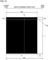
- FIG 12 illustrates an example of performing the side aligned sheet passing, in which the image forming apparatus 100 of the variation aligns the end of the paper sheet on the other side (the opposite side to the one side in the main scanning direction).
- a broken line rectangle shows one example of the image sensor 61 at the reference position.
- the reference position of the image sensor 61 may be a position where the other side end of the reading width W1 coincides with the other side end of the paper sheet.
- the reading width W1 of the image sensor 61 in the main scanning direction is smaller than the short side width of the large width sheet Pw. Further, the reading width W1 of the image sensor 61 in the main scanning direction is larger than the width of the predetermined reference paper sheet Pr size. Also in the variation, the reading width W1 of the image sensor 61 is smaller than the short side of the largest paper sheet Pm and is larger than the long side of the reference paper sheet Pr size. Note that FIG 12 illustrates the example having three types of the large width sheet Pw.
- the controller 1 controls the moving mechanism 8 to move the image sensor 61 in the main scanning direction.
- FIG 12 one example of the moved position of the image sensor 61 is shown by a solid line rectangle.
- the controller 1 controls the moving mechanism 8 to move the image sensor 61 from the reference position toward the one side.
- the controller 1 enables to read the one side edge Eg of the large width sheet Pw in the main scanning direction. Note that after the print job is finished, the controller 1 controls the moving mechanism 8 to move the image sensor 61 toward the other side.
- the controller 1 returns the image sensor 61 to the reference position.
- the movement distance L1 (the movement amount) of the image sensor 61 in the main scanning direction is determined in advance.
- the movement distance L1 is constant regardless of a size of the large width sheet Pw.
- the controller 1 moves the image sensor 61 so that the one side end thereof is positioned on the one side of the one side end of the largest paper sheet Pm without a position deviation.
- the movement distance L1 is set to any value between 1 cm and 5 cm, for example.
- a position of the large width sheet Pw in the main scanning direction may be deviated in the sheet feeding process or the sheet conveying process. Also in the case of the variation (the side aligned sheet passing), on the basis of the read image data 7, the controller 1 recognizes the deviation direction and the deviation amount of the large width sheet Pw in the main scanning direction. Also in the case of the variation, the controller 1 determines the deviation direction and the deviation amount on the basis of the detection use area R0 in the read image data 7.
- the controller 1 recognizes the sheet reading pixels 71 and the non-sheet pixels 72, for each of the line data in the main scanning direction (the main scanning line data) in the detection use area R0. Further, the controller 1 recognizes the position of the one sidemost sheet reading pixel 71 (the high density pixel) in each main scanning line data. The one sidemost sheet reading pixel 71 indicates the side edge (the edge Eg) on the one side of the large width sheet Pw. The controller 1 recognizes the one side edge pixel in the sheet reading pixels 71 for each main scanning line data. The one side edge pixel is the sheet reading pixel 71 indicating the one side end of the paper sheet in the main scanning direction.
- the controller 1 For each main scanning line data in the detection use area R0, the controller 1 multiplies the number of pixels from the other side end to the one side edge pixel in the main scanning direction by the pitch of one pixel, so as to calculate a length. The controller 1 calculates the average value of the length calculated for each main scanning line data in the detection use area R0, as the read paper sheet width W4. The controller 1 determines the read paper sheet width W4 as the distance from the other side end to the one side edge Eg of the large width sheet Pw in the main scanning direction, in the read image data 7.
- FIG 12 shows one example of the read paper sheet width W4 by a solid line arrow.
- the controller 1 compares the determined read paper sheet width W4 with the expected value W5. Also in the variation, the expected value W5 is determined in advance.
- the storage medium 2 stores the expected value W5 in a nonvolatile manner (see FIG 2 ).
- the controller 1 refers to the expected value W5 stored in the storage medium 2.
- the expected value W5 is determined for each of the types (sizes) of the large width sheet Pw.
- the expected value W5 is the read paper sheet width W4 when there is no position deviation in the main scanning direction.
- the expected value W5 is a distance from the light receiving element on the other side end of the image sensor 61 to the one side edge Eg of the large width sheet Pw. On the basis of a result of measurement, the expected value W5 can be determined in advance.
- the absolute value of the difference between the read paper sheet width W4 and the expected value W5 indicates the deviation amount of the large width sheet Pw in the main scanning direction.
- the controller 1 determines the absolute value of the difference between the expected value W5 and the determined read paper sheet width W4, as the deviation amount. On the basis of a large or small relationship between the read paper sheet width W4 and the expected value W5, the deviation direction can be recognized.
- the controller 1 recognizes the deviation direction on the basis of the large or small relationship between the expected value W5 and the determined read paper sheet width W4.
- the controller 1 subtracts the expected value W5 from the read paper sheet width W4.
- the controller 1 determines that the large width sheet Pw (the conveyed paper sheet) is shifted to the one side in the main scanning direction.
- the controller 1 determines that the large width sheet Pw (the conveyed paper sheet) is shifted to the other side in the main scanning direction.
- the controller 1 shifts the ink ejection position of the line head 49 by the recognized deviation amount in the recognized deviation direction. Specifically, the controller 1 shifts the image data to be supplied to the line head 49 in the main scanning direction, so as to adjust the printing position.
- the controller 1 checks whether or not the deviation amount is larger than the upper limit value A1. Also in the variation, the upper limit value A1 is determined in advance. In the side aligned sheet passing of the variation, the position difference of the one side edge Eg between different paper sheet sizes becomes larger than that in the case where the center sheet passing is performed. Therefore, in the variation, the upper limit value A1 can be larger than that in the embodiment. It is possible to determine more precisely that the paper sheet size is not correct (the sheet size error).
- the sheet feeder 100a performs the side aligned sheet feeding in which any size of paper sheet is fed in such a manner that the other side thereof opposite to the one side in the main scanning direction is aligned.
- the sheet conveyor 4a performs the side aligned sheet conveyance in which the paper sheet is conveyed in such a manner that the end thereof in the main scanning direction is aligned.
Landscapes
- Engineering & Computer Science (AREA)
- Multimedia (AREA)
- Signal Processing (AREA)
- Ink Jet (AREA)
- Facsimiles In General (AREA)
Claims (8)
- Bilderzeugungsvorrichtung mit einer Bogenzuführung (100a) zum Zuführen eines Papierbogens und einem Bogenförderer (4a) zum Fördern des von der Bogenzuführung (100a) zugeführten Papierbogens, wobei die Bilderzeugungsvorrichtung ferner umfasst:ein Bedienfeld (3);einen Zeilenkopf (49) mit einer Mehrzahl von Düsen, die in einer Hauptabtastrichtung senkrecht zu einer Bogenförderrichtung ausgerichtet sind, um Tinte zum Drucken aus den Düsen auf den geförderten Papierbogen auszustoßen;einen Bildsensor (61), der auf einer stromaufwärtigen Seite des Zeilenkopfes (49) in der Bogenförderrichtung angeordnet ist, um den geförderten Papierbogen in der Hauptabtastrichtung zu lesen, wobei der Bildsensor (61) ein Zeilensensor ist und eine Lesebreite (W1) in der Hauptabtastrichtung hat, die kleiner ist als die Breiten in der Hauptabtastrichtung von einigen Papierbögen unter den Papierbögen in bedruckbarer Größe;einen Bewegungsmechanismus (8) mit einem Bewegungsmotor (81) zum Bewegen des Bildsensors (61) in der Hauptabtastrichtung; undeine Steuerung (1), wobeiin einer Einstellung zur Verwendung eines Bogens großer Breite (Pw), dessen Breite in Hauptabtastrichtung größer ist als die Lesebreite (W1), zu dem Zeitpunkt, zu dem das Bedienfeld (3) den Bogens großer Breite Pw als den zu verwendenden Papierbogen annimmt, die Steuerung (1) den Bewegungsmechanismus (8) steuert, um den Bildsensor (61) von einer vorgegebenen Referenzposition zu einer gegebenen Seite in der Hauptabtastrichtung zu bewegen, so dass eine Kante (Eg) auf der gegebenen Seite unter Kanten (Eg) des Bogens großer Breite (Pw) gelesen werden kann, und bevor der Bildsensor (61) mit dem Lesen beginnt, die Steuerung (1) die Bewegung des Bildsensors (61) abschließt,die Steuerung (1) auf der Grundlage von gelesenen Bilddaten (7), die durch das Lesen durch den Bildsensor (61) erhalten wurden, eine Abweichungsrichtung und einen Abweichungsbetrag einer Position des geförderten Bogens großer Breite (Pw) in der Hauptabtastrichtung erkennt,die Steuerung (1) eine Tintenausstoßposition des Zeilenkopfes (49) um den erkannten Abweichungsbetrag in der erkannten Abweichungsrichtung verschiebt,in der Einstellung zur Verwendung des Bogens großer Breite (Pw)die Steuerung (1) in den gelesenen Bilddaten (7) eine gelesene Papierbogenbreite (W4) bestimmt, die ein Abstand von einem Pixel auf dem anderen Seitenende, das der einen Seite in der Hauptabtastrichtung gegenüberliegt, zu der Kante (Eg) auf der gegebenen Seite des Bogens großer Breite (Pw) ist,die Steuerung (1) die Abweichungsrichtung aufgrund eines Größer- oder Kleiner-Verhältnisses zwischen der ermittelten gelesenen Papierbogenbreite (W4) und einem erwarteten Wert (W5) erkennt, der eine gelesene Papierbogenbreite (W4) des Bogens großer Breite (Pw) ohne Positionsabweichung in der Hauptabtastrichtung ist,die Steuerung (1) den Abweichungsbetrag basierend auf einer Differenz zwischen dem erwarteten Wert (W5) und der ermittelten gelesenen Papierbogenbreite (W4) erkennt, undnach Beendigung eines Druckauftrags die Steuerung (1) den Bewegungsmechanismus (8) steuert, um den Bildsensor (61) zur anderen Seite zu bewegen, und den Bildsensor (61) in die Referenzposition zurückbringt.
- Bilderzeugungsvorrichtung nach Anspruch 1, bei der die Referenzposition eine Position ist, in der die Mitte der Lesebreite (W1) in der Hauptabtastrichtung mit der Mitte des geförderten Papierbogens in der Hauptabtastrichtung ohne eine Positionsabweichung in der Hauptabtastrichtung übereinstimmt, und
die Steuerung (1) den erwarteten Wert (W5) errechnet, indem sie 1/2 der Breite in Hauptabtastrichtung des zu verwendenden Bogens großer Breite (Pw) und 1/2 der Lesebreite (W1) addiert und davon eine Bewegungsstrecke des Bildsensors (61) in Hauptabtastrichtung subtrahiert. - Bilderzeugungsvorrichtung nach Anspruch 1 oder 2, bei derdie Steuerung (1) Bogenlesepixel (71), bei denen es sich um Pixel in einem Bereich handelt, in dem der Papierbogen gelesen wird, und Nichtbogenpixel (72), bei denen es sich um Pixel in einem Bereich handelt, in dem der Papierbogen nicht gelesen wird, in einem Erfassungsnutzungsbereich (RO) erkennt, der in der Bogentransportrichtung ab einem Kopf der gelesenen Bilddaten (7) eine vorgegebene Länge aufweist,die Steuerung (1) für alle Zeilendaten in der Hauptabtastrichtung des Erfassungsnutzungsbereichs (RO) ein Seitenkantenpixel erkennt, das dasjenige Bogenlesepixel (71) ist, das das Ende auf der gegebenen Seite des Papierbogens in der Hauptabtastrichtung anzeigt,die Steuerung (1) für alle Zeilendaten in der Hauptabtastrichtung des Erfassungsbereichs (RO) die Anzahl der Pixel von dem Ende auf der anderen Seite zu dem einen Seitenrandpixel in der Hauptabtastrichtung der gelesenen Bilddaten (7) mit einem Einzelpixelabstand multipliziert, um so eine Länge zu berechnen, unddie Steuerung (1) einen Durchschnittswert der berechneten Längen als die gelesene Papierbogenbreite (W4) berechnet.
- Bilderzeugungsvorrichtung nach einem der Ansprüche 1 bis 3, bei derdie Steuerung (1) Maskendaten erzeugt, die eine Freigabe oder Sperrung des Tintenausstoßes aus dem Zeilenkopf (49) definieren,die Steuerung (1) in den gelesenen Bilddaten (7) Bogenlesepixel (71), bei denen es sich um Pixel in einem Bereich handelt, in dem der Papierbogen gelesen wird, und Nichtbogenpixel (72), bei denen es sich um Pixel in einem Bereich handelt, in dem der Papierbogen nicht gelesen wird, erkennt,die Steuerung (1) in den Bogenlesepixeln (71) ein Seitenkantenpixel erkennt, das das Ende auf der gegebenen Seite des Papierbogens in der Hauptabtastrichtung anzeigt, unddie Steuerung (1) bei der Einstellung zur Verwendung des Bogens großer Breite (Pw) in den Maskendaten einen Tintenausstoß-Sperrwert für Pixel auf der einen Seite eines Pixels, das dem Kantenpixel auf der gegebenen Seite entspricht, einstellt.
- Bilderzeugungsvorrichtung nach Anspruch 4, bei der die Steuerung (1) in der Einstellung zur Verwendung des Bogens großer Breite (Pw) in den Maskendaten einen Tintenausstoß zulassenden Wert für Pixel auf der anderen Seite des Pixels einstellt, das dem Kantenpixel auf der gegebenen Seite entspricht.
- Bilderzeugungsvorrichtung nach einem der Ansprüche 1 bis 5, bei der die Steuerung (1) feststellt, dass ein Bogengrößenfehler aufgetreten ist, wenn der erkannte Abweichungsbetrag größer als ein vorgegebener oberer Grenzwert (A1) ist.
- Bilderzeugungsvorrichtung nach Anspruch 6, bei derdie Steuerung (1) Maskendaten erzeugt, die die Freigabe oder Sperrung des Tintenausstoßes aus dem Zeilenkopf (49) definieren,die Steuerung (1) in den gelesenen Bilddaten (7) Bogenlesepixel (71), bei denen es sich um Pixel in einem Bereich handelt, in dem der Papierbogen gelesen wird, und Nichtbogenpixel (72), bei denen es sich um Pixel in einem Bereich handelt, in dem der Papierbogen nicht gelesen wird, erkennt,die Steuerung (1) in den Bogenlesepixeln (71) ein Seitenkantenpixel erkennt, das das Ende auf der gegebenen Seite des Papierbogens in der Hauptabtastrichtung anzeigt, unddie Steuerung (1), wenn sie feststellt, dass ein Bogengrößenfehler aufgetreten ist, in den Maskendaten einen Tintenausstoß-Sperrwert für Pixel auf der einen Seite eines Pixels, das dem Kantenpixel auf der gegebenen Seite entspricht, und für Pixel auf der anderen Seite eines Pixels, das dem anderen seitlichsten Bogenlesepixel (71) in den gelesenen Bilddaten (7) entspricht, setzt.
- Verfahren zum Steuern einer Bilderzeugungsvorrichtung, wobei das Verfahren umfasst:Zuführen eines Papierbogens;Fördern des zugeführten Papierbogens;Verwenden eines Zeilenkopfes (49) mit einer Mehrzahl von Düsen, die in einer Hauptabtastrichtung senkrecht zu einer Bogentransportrichtung ausgerichtet sind, um durch Ausstoßen von Tinte aus den Düsen auf den transportierten Papierbogen zu drucken;Anordnen eines Bildsensors (61) auf einer stromaufwärtigen Seite des Zeilenkopfes (49) in der Bogentransportrichtung;Verwenden des Bildsensors (61) zum Lesen des geförderten Papierbogens in der Hauptabtastrichtung;wobei der Bildsensor ein Zeilensensor mit einer Lesebreite (W1) des Bildsensors (61) in der Hauptabtastrichtung ist, die kleiner ist als die Hauptabtastrichtungsbreiten einiger Papierbögen unter den Papierbögen der bedruckbaren Größe;Bewegen des Bildsensors (61) in der Hauptabtastrichtung;Bewegen des Bildsensors (61) zu dem Zeitpunkt, zu dem das Bedienfeld (3) den Bogens großer Breite Pw als den zu verwendenden Papierbogenakzeptiert, von einer vorgegebenen Referenzposition zu einer Seite in der Hauptabtastrichtung, so dass eine Kante (Eg) auf der einen Seite unter den Kanten (Eg) des Bogens großer Breite (Pw) gelesen werden kann, in einer Einstellung zur Verwendung eines Bogens großer Breite, der eine Breite in Hauptabtastrichtung hat, die großer ist als die Lesebreite (W1); Beenden der Bewegung des Bildsensors (61), bevor der Bildsensor (61) mit dem Lesen beginnt;Erkennen einer Abweichungsrichtung und eines Abweichungsbetrages einer Position des geförderten Bogens (Pw) gro-ßer Breite in der Hauptabtastrichtung, basierend auf gelesenen Bilddaten (7), die durch Lesen durch den Bildsensor (61) erhalten werden,Verschieben einer Tintenausstoßposition des Zeilenkopfes (49) um den erkannten Abweichungsbetrag in der erkannten Abweichungsrichtung,in der Einstellung zur Verwendung des Bogens großer Breite (Pw),Bestimmen einer gelesenen Papierbogenbreite (W4), die ein Abstand von einem Pixel an dem anderen Seitenende, das der gegebenen Seite in der Hauptabtastrichtung gegenüberliegt, zu der einen Seitenkante (Eg) des Bogens großer Breite (Pw) ist, in den gelesenen Bilddaten (7),Erkennen der Abweichungsrichtung auf der Grundlage eines Größer- oder Kleiner-Verhältnisses zwischen der ermittelten gelesenen Papierbogenbreite (W4) und einem erwarteten Wert (W5), der eine gelesene Papierbogenbreite (W4) des großen breiten Bogens (Pw) ohne eine Positionsabweichung in der Hauptabtastrichtung ist,Erkennen des Abweichungsbetrags basierend auf einer Differenz zwischen dem erwarteten Wert (W5) und der ermittelten gelesenen Papierbogenbreite (W4), undnach Beendigung eines Druckauftrags, Bewegen des Bildsensors (61) in Richtung der anderen Seite und Zurückführen des Bildsensors (61) in die Referenzposition.
Applications Claiming Priority (1)
| Application Number | Priority Date | Filing Date | Title |
|---|---|---|---|
| JP2019113110A JP7314641B2 (ja) | 2019-06-18 | 2019-06-18 | 画像形成装置 |
Publications (2)
| Publication Number | Publication Date |
|---|---|
| EP3753740A1 EP3753740A1 (de) | 2020-12-23 |
| EP3753740B1 true EP3753740B1 (de) | 2023-04-05 |
Family
ID=71094120
Family Applications (1)
| Application Number | Title | Priority Date | Filing Date |
|---|---|---|---|
| EP20179624.0A Active EP3753740B1 (de) | 2019-06-18 | 2020-06-12 | Bilderzeugungsvorrichtung und verfahren zur steuerung der bilderzeugungsvorrichtung |
Country Status (4)
| Country | Link |
|---|---|
| US (1) | US11267241B2 (de) |
| EP (1) | EP3753740B1 (de) |
| JP (1) | JP7314641B2 (de) |
| CN (1) | CN112104790B (de) |
Families Citing this family (4)
| Publication number | Priority date | Publication date | Assignee | Title |
|---|---|---|---|---|
| JP7325715B2 (ja) * | 2019-09-10 | 2023-08-15 | 京セラドキュメントソリューションズ株式会社 | 画像形成装置及び画像形成方法 |
| JP7394561B2 (ja) * | 2019-09-10 | 2023-12-08 | キヤノン株式会社 | 記録装置及びその制御方法 |
| JP7643136B2 (ja) * | 2021-03-26 | 2025-03-11 | 京セラドキュメントソリューションズ株式会社 | 画像形成装置 |
| JP2025009094A (ja) * | 2023-07-07 | 2025-01-20 | 京セラドキュメントソリューションズ株式会社 | 画像形成制御方法、画像形成装置 |
Family Cites Families (15)
| Publication number | Priority date | Publication date | Assignee | Title |
|---|---|---|---|---|
| JPH04181110A (ja) * | 1990-11-15 | 1992-06-29 | Tokyo Electric Co Ltd | 用紙幅自動検出装置 |
| JPH08287235A (ja) * | 1995-04-18 | 1996-11-01 | Nippon Digital Kenkyusho:Kk | イメージセンサのスキャン方法および大型イメージスキャナ |
| EP1239659A1 (de) | 2001-03-06 | 2002-09-11 | Imip Llc | Verfahren und Vorrichtung zur digitalen Herstellung eines Bilds |
| JP4110851B2 (ja) * | 2002-06-18 | 2008-07-02 | 富士ゼロックス株式会社 | 画像形成装置 |
| JP2005138489A (ja) | 2003-11-07 | 2005-06-02 | Olympus Corp | 画像形成装置の画像位置補正システム及びその画像位置補正方法 |
| JP5247140B2 (ja) * | 2007-12-26 | 2013-07-24 | キヤノン株式会社 | シート搬送装置及びその制御方法 |
| JP5426422B2 (ja) * | 2010-02-10 | 2014-02-26 | 株式会社Pfu | 画像処理装置、画像処理方法及び画像処理プログラム |
| JP5607981B2 (ja) * | 2010-04-12 | 2014-10-15 | 株式会社Pfu | 画像読取装置 |
| JP2012090085A (ja) | 2010-10-20 | 2012-05-10 | Seiko Epson Corp | 原稿読取装置 |
| JP6000194B2 (ja) | 2013-06-28 | 2016-09-28 | 京セラドキュメントソリューションズ株式会社 | シート検出装置、画像形成装置 |
| JP6332081B2 (ja) * | 2015-03-02 | 2018-05-30 | 京セラドキュメントソリューションズ株式会社 | 読取装置及びこれを備えた画像形成装置 |
| WO2017022311A1 (ja) * | 2015-08-06 | 2017-02-09 | 京セラドキュメントソリューションズ株式会社 | 穿孔装置、シート処理装置、画像形成システム |
| JP6705199B2 (ja) * | 2016-02-15 | 2020-06-03 | セイコーエプソン株式会社 | 印刷装置 |
| JP6624039B2 (ja) * | 2016-12-15 | 2019-12-25 | 京セラドキュメントソリューションズ株式会社 | インクジェット記録装置 |
| JP6690561B2 (ja) | 2017-01-23 | 2020-04-28 | 京セラドキュメントソリューションズ株式会社 | 画像形成装置 |
-
2019
- 2019-06-18 JP JP2019113110A patent/JP7314641B2/ja active Active
-
2020
- 2020-06-12 US US16/900,379 patent/US11267241B2/en active Active
- 2020-06-12 EP EP20179624.0A patent/EP3753740B1/de active Active
- 2020-06-17 CN CN202010552946.4A patent/CN112104790B/zh active Active
Also Published As
| Publication number | Publication date |
|---|---|
| JP7314641B2 (ja) | 2023-07-26 |
| EP3753740A1 (de) | 2020-12-23 |
| JP2020203452A (ja) | 2020-12-24 |
| US11267241B2 (en) | 2022-03-08 |
| CN112104790A (zh) | 2020-12-18 |
| US20200398555A1 (en) | 2020-12-24 |
| CN112104790B (zh) | 2022-06-03 |
Similar Documents
| Publication | Publication Date | Title |
|---|---|---|
| EP3753740B1 (de) | Bilderzeugungsvorrichtung und verfahren zur steuerung der bilderzeugungsvorrichtung | |
| US8770698B2 (en) | Print control method and print apparatus | |
| US8833893B2 (en) | Method of printing and printing apparatus | |
| US10279606B2 (en) | Printing apparatus for controlling overlap of a preceding sheet and a succeeding sheet and a related control method | |
| US8757909B2 (en) | Image forming apparatus with cutting unit | |
| US8757757B2 (en) | Printing apparatus | |
| US20110211008A1 (en) | Print apparatus | |
| US9469129B2 (en) | Printing method and apparatus for performing conveyance control using marks in non-image areas | |
| US10994557B2 (en) | Printing apparatus and control method | |
| US9073309B1 (en) | Apparatus and method for recording | |
| US8246262B2 (en) | Print media processing apparatus and media transportation control method for the same | |
| CN116021887A (zh) | 图像形成装置 | |
| JP6610181B2 (ja) | 液滴吐出装置 | |
| WO2023054371A1 (ja) | 画像形成装置 | |
| JP2008182352A (ja) | 位置特定方法、位置特定装置、及び、プログラム | |
| US10897543B2 (en) | Image forming apparatus and method of controlling image forming apparatus | |
| JP6296873B2 (ja) | プリント装置および記録位置調整方法 | |
| CN111752118A (zh) | 图像形成装置 | |
| JP7415564B2 (ja) | 画像形成装置 | |
| US20210170751A1 (en) | Image forming apparatus | |
| CN118849618A (zh) | 图像形成装置 | |
| JP2008190948A (ja) | 位置特定方法、位置特定装置、及び、プログラム |
Legal Events
| Date | Code | Title | Description |
|---|---|---|---|
| PUAI | Public reference made under article 153(3) epc to a published international application that has entered the european phase |
Free format text: ORIGINAL CODE: 0009012 |
|
| STAA | Information on the status of an ep patent application or granted ep patent |
Free format text: STATUS: THE APPLICATION HAS BEEN PUBLISHED |
|
| AK | Designated contracting states |
Kind code of ref document: A1 Designated state(s): AL AT BE BG CH CY CZ DE DK EE ES FI FR GB GR HR HU IE IS IT LI LT LU LV MC MK MT NL NO PL PT RO RS SE SI SK SM TR |
|
| AX | Request for extension of the european patent |
Extension state: BA ME |
|
| STAA | Information on the status of an ep patent application or granted ep patent |
Free format text: STATUS: REQUEST FOR EXAMINATION WAS MADE |
|
| 17P | Request for examination filed |
Effective date: 20210617 |
|
| RBV | Designated contracting states (corrected) |
Designated state(s): AL AT BE BG CH CY CZ DE DK EE ES FI FR GB GR HR HU IE IS IT LI LT LU LV MC MK MT NL NO PL PT RO RS SE SI SK SM TR |
|
| REG | Reference to a national code |
Ref country code: DE Ref legal event code: R079 Ref document number: 602020009374 Country of ref document: DE Free format text: PREVIOUS MAIN CLASS: B41J0011000000 Ipc: H04N0001000000 |
|
| GRAP | Despatch of communication of intention to grant a patent |
Free format text: ORIGINAL CODE: EPIDOSNIGR1 |
|
| STAA | Information on the status of an ep patent application or granted ep patent |
Free format text: STATUS: GRANT OF PATENT IS INTENDED |
|
| RIC1 | Information provided on ipc code assigned before grant |
Ipc: B41J 11/00 20060101ALI20221011BHEP Ipc: H04N 1/00 20060101AFI20221011BHEP |
|
| INTG | Intention to grant announced |
Effective date: 20221025 |
|
| GRAS | Grant fee paid |
Free format text: ORIGINAL CODE: EPIDOSNIGR3 |
|
| GRAA | (expected) grant |
Free format text: ORIGINAL CODE: 0009210 |
|
| STAA | Information on the status of an ep patent application or granted ep patent |
Free format text: STATUS: THE PATENT HAS BEEN GRANTED |
|
| AK | Designated contracting states |
Kind code of ref document: B1 Designated state(s): AL AT BE BG CH CY CZ DE DK EE ES FI FR GB GR HR HU IE IS IT LI LT LU LV MC MK MT NL NO PL PT RO RS SE SI SK SM TR |
|
| REG | Reference to a national code |
Ref country code: GB Ref legal event code: FG4D |
|
| REG | Reference to a national code |
Ref country code: DE Ref legal event code: R096 Ref document number: 602020009374 Country of ref document: DE |
|
| REG | Reference to a national code |
Ref country code: CH Ref legal event code: EP |
|
| REG | Reference to a national code |
Ref country code: AT Ref legal event code: REF Ref document number: 1559146 Country of ref document: AT Kind code of ref document: T Effective date: 20230415 |
|
| REG | Reference to a national code |
Ref country code: IE Ref legal event code: FG4D |
|
| P01 | Opt-out of the competence of the unified patent court (upc) registered |
Effective date: 20230420 |
|
| REG | Reference to a national code |
Ref country code: LT Ref legal event code: MG9D |
|
| REG | Reference to a national code |
Ref country code: NL Ref legal event code: MP Effective date: 20230405 |
|
| REG | Reference to a national code |
Ref country code: AT Ref legal event code: MK05 Ref document number: 1559146 Country of ref document: AT Kind code of ref document: T Effective date: 20230405 |
|
| PG25 | Lapsed in a contracting state [announced via postgrant information from national office to epo] |
Ref country code: NL Free format text: LAPSE BECAUSE OF FAILURE TO SUBMIT A TRANSLATION OF THE DESCRIPTION OR TO PAY THE FEE WITHIN THE PRESCRIBED TIME-LIMIT Effective date: 20230405 |
|
| PG25 | Lapsed in a contracting state [announced via postgrant information from national office to epo] |
Ref country code: SE Free format text: LAPSE BECAUSE OF FAILURE TO SUBMIT A TRANSLATION OF THE DESCRIPTION OR TO PAY THE FEE WITHIN THE PRESCRIBED TIME-LIMIT Effective date: 20230405 Ref country code: PT Free format text: LAPSE BECAUSE OF FAILURE TO SUBMIT A TRANSLATION OF THE DESCRIPTION OR TO PAY THE FEE WITHIN THE PRESCRIBED TIME-LIMIT Effective date: 20230807 Ref country code: NO Free format text: LAPSE BECAUSE OF FAILURE TO SUBMIT A TRANSLATION OF THE DESCRIPTION OR TO PAY THE FEE WITHIN THE PRESCRIBED TIME-LIMIT Effective date: 20230705 Ref country code: ES Free format text: LAPSE BECAUSE OF FAILURE TO SUBMIT A TRANSLATION OF THE DESCRIPTION OR TO PAY THE FEE WITHIN THE PRESCRIBED TIME-LIMIT Effective date: 20230405 Ref country code: AT Free format text: LAPSE BECAUSE OF FAILURE TO SUBMIT A TRANSLATION OF THE DESCRIPTION OR TO PAY THE FEE WITHIN THE PRESCRIBED TIME-LIMIT Effective date: 20230405 |
|
| PG25 | Lapsed in a contracting state [announced via postgrant information from national office to epo] |
Ref country code: RS Free format text: LAPSE BECAUSE OF FAILURE TO SUBMIT A TRANSLATION OF THE DESCRIPTION OR TO PAY THE FEE WITHIN THE PRESCRIBED TIME-LIMIT Effective date: 20230405 Ref country code: PL Free format text: LAPSE BECAUSE OF FAILURE TO SUBMIT A TRANSLATION OF THE DESCRIPTION OR TO PAY THE FEE WITHIN THE PRESCRIBED TIME-LIMIT Effective date: 20230405 Ref country code: LV Free format text: LAPSE BECAUSE OF FAILURE TO SUBMIT A TRANSLATION OF THE DESCRIPTION OR TO PAY THE FEE WITHIN THE PRESCRIBED TIME-LIMIT Effective date: 20230405 Ref country code: LT Free format text: LAPSE BECAUSE OF FAILURE TO SUBMIT A TRANSLATION OF THE DESCRIPTION OR TO PAY THE FEE WITHIN THE PRESCRIBED TIME-LIMIT Effective date: 20230405 Ref country code: IS Free format text: LAPSE BECAUSE OF FAILURE TO SUBMIT A TRANSLATION OF THE DESCRIPTION OR TO PAY THE FEE WITHIN THE PRESCRIBED TIME-LIMIT Effective date: 20230805 Ref country code: HR Free format text: LAPSE BECAUSE OF FAILURE TO SUBMIT A TRANSLATION OF THE DESCRIPTION OR TO PAY THE FEE WITHIN THE PRESCRIBED TIME-LIMIT Effective date: 20230405 Ref country code: GR Free format text: LAPSE BECAUSE OF FAILURE TO SUBMIT A TRANSLATION OF THE DESCRIPTION OR TO PAY THE FEE WITHIN THE PRESCRIBED TIME-LIMIT Effective date: 20230706 Ref country code: AL Free format text: LAPSE BECAUSE OF FAILURE TO SUBMIT A TRANSLATION OF THE DESCRIPTION OR TO PAY THE FEE WITHIN THE PRESCRIBED TIME-LIMIT Effective date: 20230405 |
|
| PG25 | Lapsed in a contracting state [announced via postgrant information from national office to epo] |
Ref country code: FI Free format text: LAPSE BECAUSE OF FAILURE TO SUBMIT A TRANSLATION OF THE DESCRIPTION OR TO PAY THE FEE WITHIN THE PRESCRIBED TIME-LIMIT Effective date: 20230405 |
|
| REG | Reference to a national code |
Ref country code: DE Ref legal event code: R097 Ref document number: 602020009374 Country of ref document: DE |
|
| PG25 | Lapsed in a contracting state [announced via postgrant information from national office to epo] |
Ref country code: SK Free format text: LAPSE BECAUSE OF FAILURE TO SUBMIT A TRANSLATION OF THE DESCRIPTION OR TO PAY THE FEE WITHIN THE PRESCRIBED TIME-LIMIT Effective date: 20230405 |
|
| PG25 | Lapsed in a contracting state [announced via postgrant information from national office to epo] |
Ref country code: MC Free format text: LAPSE BECAUSE OF FAILURE TO SUBMIT A TRANSLATION OF THE DESCRIPTION OR TO PAY THE FEE WITHIN THE PRESCRIBED TIME-LIMIT Effective date: 20230405 |
|
| PG25 | Lapsed in a contracting state [announced via postgrant information from national office to epo] |
Ref country code: SM Free format text: LAPSE BECAUSE OF FAILURE TO SUBMIT A TRANSLATION OF THE DESCRIPTION OR TO PAY THE FEE WITHIN THE PRESCRIBED TIME-LIMIT Effective date: 20230405 Ref country code: SK Free format text: LAPSE BECAUSE OF FAILURE TO SUBMIT A TRANSLATION OF THE DESCRIPTION OR TO PAY THE FEE WITHIN THE PRESCRIBED TIME-LIMIT Effective date: 20230405 Ref country code: RO Free format text: LAPSE BECAUSE OF FAILURE TO SUBMIT A TRANSLATION OF THE DESCRIPTION OR TO PAY THE FEE WITHIN THE PRESCRIBED TIME-LIMIT Effective date: 20230405 Ref country code: MC Free format text: LAPSE BECAUSE OF FAILURE TO SUBMIT A TRANSLATION OF THE DESCRIPTION OR TO PAY THE FEE WITHIN THE PRESCRIBED TIME-LIMIT Effective date: 20230405 Ref country code: EE Free format text: LAPSE BECAUSE OF FAILURE TO SUBMIT A TRANSLATION OF THE DESCRIPTION OR TO PAY THE FEE WITHIN THE PRESCRIBED TIME-LIMIT Effective date: 20230405 Ref country code: DK Free format text: LAPSE BECAUSE OF FAILURE TO SUBMIT A TRANSLATION OF THE DESCRIPTION OR TO PAY THE FEE WITHIN THE PRESCRIBED TIME-LIMIT Effective date: 20230405 Ref country code: CZ Free format text: LAPSE BECAUSE OF FAILURE TO SUBMIT A TRANSLATION OF THE DESCRIPTION OR TO PAY THE FEE WITHIN THE PRESCRIBED TIME-LIMIT Effective date: 20230405 |
|
| REG | Reference to a national code |
Ref country code: CH Ref legal event code: PL |
|
| PLBE | No opposition filed within time limit |
Free format text: ORIGINAL CODE: 0009261 |
|
| STAA | Information on the status of an ep patent application or granted ep patent |
Free format text: STATUS: NO OPPOSITION FILED WITHIN TIME LIMIT |
|
| REG | Reference to a national code |
Ref country code: BE Ref legal event code: MM Effective date: 20230630 |
|
| PG25 | Lapsed in a contracting state [announced via postgrant information from national office to epo] |
Ref country code: LU Free format text: LAPSE BECAUSE OF NON-PAYMENT OF DUE FEES Effective date: 20230612 |
|
| 26N | No opposition filed |
Effective date: 20240108 |
|
| REG | Reference to a national code |
Ref country code: IE Ref legal event code: MM4A |
|
| PG25 | Lapsed in a contracting state [announced via postgrant information from national office to epo] |
Ref country code: LU Free format text: LAPSE BECAUSE OF NON-PAYMENT OF DUE FEES Effective date: 20230612 |
|
| PG25 | Lapsed in a contracting state [announced via postgrant information from national office to epo] |
Ref country code: IE Free format text: LAPSE BECAUSE OF NON-PAYMENT OF DUE FEES Effective date: 20230612 |
|
| PG25 | Lapsed in a contracting state [announced via postgrant information from national office to epo] |
Ref country code: IE Free format text: LAPSE BECAUSE OF NON-PAYMENT OF DUE FEES Effective date: 20230612 Ref country code: CH Free format text: LAPSE BECAUSE OF NON-PAYMENT OF DUE FEES Effective date: 20230630 |
|
| PG25 | Lapsed in a contracting state [announced via postgrant information from national office to epo] |
Ref country code: SI Free format text: LAPSE BECAUSE OF FAILURE TO SUBMIT A TRANSLATION OF THE DESCRIPTION OR TO PAY THE FEE WITHIN THE PRESCRIBED TIME-LIMIT Effective date: 20230405 |
|
| PG25 | Lapsed in a contracting state [announced via postgrant information from national office to epo] |
Ref country code: SI Free format text: LAPSE BECAUSE OF FAILURE TO SUBMIT A TRANSLATION OF THE DESCRIPTION OR TO PAY THE FEE WITHIN THE PRESCRIBED TIME-LIMIT Effective date: 20230405 Ref country code: IT Free format text: LAPSE BECAUSE OF FAILURE TO SUBMIT A TRANSLATION OF THE DESCRIPTION OR TO PAY THE FEE WITHIN THE PRESCRIBED TIME-LIMIT Effective date: 20230405 Ref country code: FR Free format text: LAPSE BECAUSE OF NON-PAYMENT OF DUE FEES Effective date: 20230630 Ref country code: BE Free format text: LAPSE BECAUSE OF NON-PAYMENT OF DUE FEES Effective date: 20230630 |
|
| PG25 | Lapsed in a contracting state [announced via postgrant information from national office to epo] |
Ref country code: BG Free format text: LAPSE BECAUSE OF FAILURE TO SUBMIT A TRANSLATION OF THE DESCRIPTION OR TO PAY THE FEE WITHIN THE PRESCRIBED TIME-LIMIT Effective date: 20230405 |
|
| PG25 | Lapsed in a contracting state [announced via postgrant information from national office to epo] |
Ref country code: BG Free format text: LAPSE BECAUSE OF FAILURE TO SUBMIT A TRANSLATION OF THE DESCRIPTION OR TO PAY THE FEE WITHIN THE PRESCRIBED TIME-LIMIT Effective date: 20230405 |
|
| GBPC | Gb: european patent ceased through non-payment of renewal fee |
Effective date: 20240612 |
|
| PG25 | Lapsed in a contracting state [announced via postgrant information from national office to epo] |
Ref country code: GB Free format text: LAPSE BECAUSE OF NON-PAYMENT OF DUE FEES Effective date: 20240612 |
|
| PGFP | Annual fee paid to national office [announced via postgrant information from national office to epo] |
Ref country code: DE Payment date: 20250520 Year of fee payment: 6 |
|
| PG25 | Lapsed in a contracting state [announced via postgrant information from national office to epo] |
Ref country code: CY Free format text: LAPSE BECAUSE OF FAILURE TO SUBMIT A TRANSLATION OF THE DESCRIPTION OR TO PAY THE FEE WITHIN THE PRESCRIBED TIME-LIMIT; INVALID AB INITIO Effective date: 20200612 |
|
| PG25 | Lapsed in a contracting state [announced via postgrant information from national office to epo] |
Ref country code: HU Free format text: LAPSE BECAUSE OF FAILURE TO SUBMIT A TRANSLATION OF THE DESCRIPTION OR TO PAY THE FEE WITHIN THE PRESCRIBED TIME-LIMIT; INVALID AB INITIO Effective date: 20200612 |
|
| PG25 | Lapsed in a contracting state [announced via postgrant information from national office to epo] |
Ref country code: TR Free format text: LAPSE BECAUSE OF FAILURE TO SUBMIT A TRANSLATION OF THE DESCRIPTION OR TO PAY THE FEE WITHIN THE PRESCRIBED TIME-LIMIT Effective date: 20230405 |