EP3757006B1 - Voie de mise à la terre électronique optimisée pour le bruit haute fréquence - Google Patents
Voie de mise à la terre électronique optimisée pour le bruit haute fréquence Download PDFInfo
- Publication number
- EP3757006B1 EP3757006B1 EP20150785.2A EP20150785A EP3757006B1 EP 3757006 B1 EP3757006 B1 EP 3757006B1 EP 20150785 A EP20150785 A EP 20150785A EP 3757006 B1 EP3757006 B1 EP 3757006B1
- Authority
- EP
- European Patent Office
- Prior art keywords
- control unit
- unit housing
- coupled
- aircraft galley
- outer cover
- Prior art date
- Legal status (The legal status is an assumption and is not a legal conclusion. Google has not performed a legal analysis and makes no representation as to the accuracy of the status listed.)
- Active
Links
Images


Classifications
-
- B—PERFORMING OPERATIONS; TRANSPORTING
- B64—AIRCRAFT; AVIATION; COSMONAUTICS
- B64D—EQUIPMENT FOR FITTING IN OR TO AIRCRAFT; FLIGHT SUITS; PARACHUTES; ARRANGEMENT OR MOUNTING OF POWER PLANTS OR PROPULSION TRANSMISSIONS IN AIRCRAFT
- B64D11/00—Passenger or crew accommodation; Flight-deck installations not otherwise provided for
- B64D11/04—Galleys
-
- F—MECHANICAL ENGINEERING; LIGHTING; HEATING; WEAPONS; BLASTING
- F24—HEATING; RANGES; VENTILATING
- F24C—DOMESTIC STOVES OR RANGES ; DETAILS OF DOMESTIC STOVES OR RANGES, OF GENERAL APPLICATION
- F24C15/00—Details
- F24C15/16—Shelves, racks or trays inside ovens; Supports therefor
-
- H—ELECTRICITY
- H05—ELECTRIC TECHNIQUES NOT OTHERWISE PROVIDED FOR
- H05K—PRINTED CIRCUITS; CASINGS OR CONSTRUCTIONAL DETAILS OF ELECTRIC APPARATUS; MANUFACTURE OF ASSEMBLAGES OF ELECTRICAL COMPONENTS
- H05K9/00—Screening of apparatus or components against electric or magnetic fields
- H05K9/0007—Casings
Definitions
- EMI electromagnetic interference
- High-frequency noise e.g., EMI
- RE radiated emissions
- the method may include: coupling one or more electronic components of an aircraft galley insert to a control unit housing; coupling one or more operating load components to one or more conductive coupling structures; coupling the control unit housing to the one or more conductive coupling structures; electrically coupling the one or more electronic components to the one or more operating load components via one or more electrical lines; transferring radiated emissions produced by the one or more electronic components from the one or more conductive coupling structures to the control unit housing via at least one of a capacitive coupling or a conductive coupling between the one or more conductive coupling structures and the control unit housing; and transferring the radiated emissions from the control unit housing to the one or more electronic components via at least one of a capacitive coupling or a conductive coupling between the control unit housing and the one or more electronic components.
- inventive concepts are not limited in their application to the details of construction and the arrangement of the components or steps or methodologies set forth in the following description or illustrated in the drawings.
- inventive concepts disclosed herein may be practiced without these specific details.
- well-known features may not be described in detail to avoid unnecessarily complicating the instant disclosure.
- inventive concepts disclosed herein are capable of other embodiments or of being practiced or carried out in various ways. Also, it is to be understood that the phraseology and terminology employed herein is for the purpose of description and should not be regarded as limiting.
- a letter following a reference numeral is intended to reference an embodiment of the feature or element that may be similar, but not necessarily identical, to a previously described element or feature bearing the same reference numeral (e.g., 1, 1A, 1B).
- reference numeral e.g. 1, 1A, 1B
- Such shorthand notations are used for purposes of convenience only, and should not be construed to limit the inventive concepts disclosed herein in any way unless expressly stated to the contrary.
- any reference to "one embodiment,” or “some embodiments” means that a particular element, feature, structure, or characteristic described in connection with the embodiment is included in at least one embodiment of the inventive concepts disclosed herein.
- the appearances of the phrase “in some embodiments” in various places in the specification are not necessarily all referring to the same embodiment, and embodiments of the inventive concepts disclosed may include one or more of the features expressly described or inherently present herein, or any combination of sub-combination of two or more such features, along with any other features which may not necessarily be expressly described or inherently present in the instant disclosure.
- EMI electromagnetic interference
- RE radiated emissions
- RS radiated susceptibility
- unwanted noise e.g., RE
- RE unwanted noise
- manufacturing electronic devices with efficient, optimized return paths between a power source and load which are unobstructed as possible is crucial to the minimization of EMI and RE.
- FIG. 1 illustrates a simplified view of a non-optimized grounding path of an electronic device.
- FIG. 1 may be provided as an example of a non-optimized grounding path of currently available electronic devices, against which embodiments of the present disclosure may be compared.
- aircraft galley inserts including aircraft galley ovens 102, provide sub-optimal grounding paths for returning high-frequency noise (e.g., RE) emitted by the electrical components of the galley inserts.
- RE high-frequency noise
- FIG. 1 in many electronic devices (e.g., aircraft galley oven 102), an electronic power source (e.g., power supply modules) and load (e.g., pumps, valves, human machine interfaces, and the like) of the electronic device (aircraft galley oven 102) are coupled via power and return wiring.
- a majority of the current and noise will typically flow within the power and the return wiring, thus the area between the power and return wiring is typically kept as small as possible to reduce the known area of RE and RS ("Known RE/RS area").
- the return path for noise back to the source typically is not optimal due to mutual capacitance. Accordingly, a portion of the current/noise within the electronic device will travel back to the source by any number of return paths as uncontrolled radiated emissions (RE), leading to large, uncontrolled areas of RE (“Uncontrolled/Unknown RE/RS area”), thereby making the electronic device more susceptible.
- RE uncontrolled radiated emissions
- current aircraft galley inserts often utilize oven control unit housings which exhibit high resistances, thereby inhibiting the return RE and EMI back to electronic components of the aircraft galley inserts.
- current galley insert designs include many components, and therefore many transitions between components/parts which are physically different (e.g., "surface jumps") along grounding paths, thereby increasing the size of the uncontrolled/unknown RE/RS area, increasing bonding resistance, and further inhibiting the return of high-frequency noise (e.g., RE) back to the source.
- contact surfaces along the grounding path of current galley inserts are typically small, limiting the ability of the grounding path to return RE via capacitive coupling. Therefore, it would be desirable to provide a system which cures one or more of the shortfalls of the previous approaches identified above.
- embodiments of the present disclosure are directed to a grounding path for electronic devices (e.g., galley inserts, galley ovens) which reduces the length of the grounding path, reduces the number of "surface jumps" along the grounding path, increases the area of contact surfaces in order to optimize the efficiency of the grounding path, and reduces the uncontrolled area of radiated emissions (RE) within electronic devices.
- electronic devices e.g., galley inserts, galley ovens
- FIG. 2 illustrates a simplified view of an optimized grounding path of an electronic device, in accordance with one or more embodiments of the present disclosure.
- Some embodiments of the present disclosure are directed to reducing and controlling the uncontrolled/unknown RE/RS area shown in FIG. 1 .
- some embodiments of the present disclosure are directed to coupling a source and a load of an electronic device to one or more conductive coupling structures in order to create a known, controlled RE/RS area for radiated emissions (RE) to return to the source.
- a source and load of an electronic device e.g., aircraft galley oven 102
- the one or more coupling structures may include any conductive coupling structures of the electronic device known in the art including, but not limited to, a control unit housing, an outer cover, a conductive structural component, and the like.
- RE radiated emissions
- the area which contributes to radiated emissions (RE) e.g., "Controlled RE/RS area”
- high-frequency noise e.g., EMI
- galley insert an electronic device
- embodiments of the inventive concepts disclosed herein are directed to an optimized electronics grounding path for radiated emissions (RE). More particularly, embodiments of the present disclosure are directed to an optimized grounding path for high-frequency noise (e.g., RE) generated by electronic devices (e.g., galley inserts, and the like). Additional embodiments of the present disclosure are directed to electronic devices which utilize structural components of the electronic device as conductive coupling structures (e.g., chassis, frame, control unit housing, outer cover, and the like) to create optimized and defined grounding paths which direct EMI (e.g., RE) back to various power sources. Further embodiments of the present disclosure are directed to a galley insert with an optimized grounding path for high-frequency noise.
- conductive coupling structures e.g., chassis, frame, control unit housing, outer cover, and the like
- FIG. 3 illustrates an aircraft environment 100 including aircraft-compliant galley inserts, in accordance with an example embodiment of the present disclosure. More specifically, FIG. 3 illustrates an aircraft environment 100 (e.g., aircraft galley) including various galley inserts (e.g., aircraft-compliant galley coffee maker, and a plurality of aircraft galley ovens 102a, 102b).
- aircraft environment 100 e.g., aircraft galley
- various galley inserts e.g., aircraft-compliant galley coffee maker, and a plurality of aircraft galley ovens 102a, 102b.
- inventive concepts of the present disclosure may be applied in any type of electronic device or galley insert known in the art.
- inventive concepts of the present disclosure may be used to optimize grounding paths within non-aircraft appliances, including commercial appliances, residential appliances, and the like.
- inventive concepts of the present disclosure may be used in the context of alternative and/or additional galley inserts including, but not limited to, coffee makers, beverage carts, chillers, trash compactors, and the like.
- the embodiments of the present disclosure may be configured in accordance with avionics guidelines and/or standards put forth by, but not limited to, the Federal Aviation Administration (FAA), the European Aviation Safety Agency (EASA) or any other flight certification agency or organization; the American National Standards Institute (ANSI), Aeronautical Radio, Incorporated (ARINC), or any other standards setting organization or company; the Radio Technical Commission for Aeronautics (RTCA) or any other guidelines agency or organization; or the like.
- FAA Federal Aviation Administration
- EASA European Aviation Safety Agency
- ARINC Aeronautical Radio, Incorporated
- RTCA Radio Technical Commission for Aeronautics
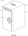
- FIG. 4A illustrates a front perspective view of an aircraft galley oven 102, in accordance with an example embodiment of the present disclosure.
- the aircraft galley oven 102 may include, but is not limited to, an oven body 103 and an oven door 104 hingedly coupled to the oven body 103.
- the oven door 104 may include a handle 106.
- the oven body 103 includes an outer cover 108 defining one or more exterior surfaces of the oven body 103.
- the oven body 103 may further include a top cover 110 defining a top exterior surface of the oven body 103.
- the top cover 110 may be configured to detachably couple to the outer cover 108.
- the top cover 110 may include one or more structures configured to facilitate carrying and movement of the aircraft galley oven 102. For example, as shown in FIG. 4A , the top cover 110 may include one or more handles 112.
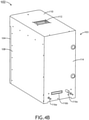
- FIG. 4B illustrates a rear perspective view of an aircraft galley oven 102, in accordance with an example embodiment of the present disclosure.
- aircraft galley oven 102 may include a rear cover 114 defining a rear exterior surface of the oven body 103.
- the rear cover 114 may be configured to be detachably coupled to the outer cover 108 and/or the top cover 102.
- Various components of the oven body 103 e.g., outer cover 108, top cover 110, rear cover 114) may be formed using any material known in the art.
- the outer cover 108, top cover 110, and/or rear cover 114 may be formed from sheets of aluminum.
- the aircraft galley oven 102 may include one or more ports/couplers 116 configured to couple the aircraft galley oven 102 to various other sources or systems (e.g., electricity sources, compressed air sources, and the like).
- FIG. 4C illustrates a rear perspective view of an aircraft galley oven 102 including a control unit 120, in accordance with an example embodiment of the present disclosure. More particularly, FIG. 4C illustrates a rear perspective view of the aircraft galley oven 102 with the top cover 110 and the rear cover 114 removed from the oven body 103. As shown in FIG. 4C , aircraft galley oven 102 may include, but is not limited to, an aircraft body 103, a control unit 120, one or more operating load components 126, and one or more fans 128.
- control unit 120 includes one or more electronic components within a control unit housing 121 configured to operate the various functions of the aircraft galley oven 102.
- the control unit 120 may include one or more electronic components disposed on a printed circuit board within a control unit housing 121.
- Electrical components of the control unit 120 may include, but are not limited to, power supply modules, transistors, resistors, and electrical circuits configured to carry out the various functions of the aircraft galley oven 102.
- the control unit 120 includes a control unit housing 121 configured to contain and/or protect the electronic components of the aircraft oven (e.g., contain the printed circuit board including electronic components).
- the control unit housing 121 includes a base plate 122 which may define at least a portion of the control unit housing 121.
- the control unit 120 may be mounted and/or coupled to the oven body 103.
- the control unit 120 is coupled to the outer cover 108.
- the control unit housing 121 of the control unit 120 may be coupled to the outer cover 108.
- the base plate 122 of the control unit housing 121 may be coupled to the outer cover 108.
- the control unit 120 (e.g., control unit housing 121) may be coupled to one or more faying surfaces 118 of the outer cover 108.
- the base plate 122 of the control unit housing 121 may be coupled to the outer cover 108 in such a manner as to increase the contact surface area between the base plate 122 (e.g., control unit housing 121) and the outer cover 108.
- control unit housing 121 may optimize a grounding return path for high-frequency noise (e.g., RE) back to the electrical components of the control unit 120.
- RE high-frequency noise
- embodiments of the present disclosure are directed to an optimized grounding path for electronic devices, wherein the optimized grounding path provides an efficient return path for noise (RE) to return to the sources of EMI within the control unit 120.
- embodiments of the present disclosure are directed to an optimized return path which decreases the length of noise grounding paths back to sources of EMI within the control unit 120.
- Further embodiments of the present disclosure are directed to an optimized return path which provides low resistance for high frequencies along a return path to the control unit 120.
- the aircraft galley oven 102 includes one or more electrical lines 124 (e.g., wiring, wires, traces, and the like) configured to communicatively couple the electrical components of the control unit 120 to various other operating load components 126 of the aircraft galley oven 102.
- electrical component of the control unit 120 may be regarded as electrical power "sources”
- operating load components 126 may be regarded as electrical "loads,” as shown and described in FIG. 2 .
- Operating components 126 may include any components known in the art for operating an oven including, but not limited to, one or more heating elements, one or more compressors, one or more pumps, one or more valves, and the like.
- operating load components 126 may be regarded as referring to any components of an electronic device (e.g., aircraft galley insert, aircraft galley oven 102, and the like) which are communicatively coupled (either directly or indirectly) to the electrical components within the control unit 120.
- the aircraft galley oven 102 may further include one or more fans 128 configured to cool and maintain an operating temperature of the control unit 120.
- FIG. 5 illustrates a control unit 120, in accordance with an example embodiment of the present disclosure.
- the control unit 120 may include, but is not limited to, a control unit housing 121 and one or more electrical components disposed on a printed circuit board (PCB) within the control unit housing 121.
- PCB printed circuit board
- the control unit housing 121 may include, but is not limited to, a base plate 122 coupled to a control unit cover 130.
- the base plate 122 may be coupled and/or mounted to the control unit cover 130 using any technique known in the art.
- the control unit housing 121 e.g., base plate 122, control unit cover 130, and the like
- the control unit housing 121 is configured to contain the printed circuit board upon which one or more electrical components of the aircraft galley oven 102 are disposed.
- the control unit cover 130 may be configured to close off the control unit 120 in order to keep radiation within the control unit 120, as well as keep dust, moisture, and debris out of the control unit 120.
- the base plate 122 may be formed from any material known in the art which is configured to provide a low resistance return path for EMI noise (e.g., RE) back to the one or more electrical components disposed on the PCB.
- the base plate 122 may be formed from, but is not limited to, aluminum, steel, titanium, and the like.
- base plate 122 may include a single machined or casted aluminum structure.
- the control unit housing 121 e.g., the base plate 122 and the control unit cover 130
- the base plate 122 may be formed from a plastic which is made to be conductive via one or more conductive coatings or conductive fibers.
- the control unit 120 may further include one or more ports 132 configured to receive the one or more electrical lines 124 ( FIG. 4C ) configured to communicatively couple the one or more electrical components within the control unit 120 to the various other operating load components 126 of the aircraft galley oven 102.
- the one or more electrical components within the control unit 120 may be coupled to one or more operating load components 126 via one or more conductive coupling structures including, but not limited to, the control unit housing 121, the outer cover 108, a conductive structural component, and the like.
- FIG. 6 illustrates a bottom view of a base plate 122 of a control unit housing 121, in accordance with an example embodiment of the present disclosure.
- the base plate 122 may be formed from a single machined or casted piece of aluminum.
- the base plate 122 e.g., aluminum base plate 122
- the non-anodized conductive layer may include any non-anodized conductive layer known in the art including, but not limited to, SurTec coatings.
- the base plate 122 may include one or more stand-offs 134.
- the base plate 122 may include a first stand-off 134a, a second stand-off 134b, a third stand-off 134c, and the like.
- the base plate 122 may be coupled to a PCB 138 (shown in FIG. 7 ) within the control unit 120 at the one or more stand-offs 134.
- the one or more stand-offs 134 may be configured to receive fasteners (e.g., bolts, screws, pins, or the like) in order to couple the base plate 122 to the PCB 138.
- the one or more stand-offs 134 may allow the base plate 122 to be coupled to the PCB 138 while also providing sufficient space for the electronic components disposed on the PCB 138.
- the base plate 122 and the control unit cover 130 of the control unit housing 121 may be formed as a single piece to house the components of the control unit 120.
- the control unit housing 121 may include a single piece. The base plate 122 and stand-offs 134 will be discussed in further detail with respect to FIG. 7 .
- FIG. 7 illustrates a cross sectional view of a control unit 120, in accordance with an example embodiment of the present disclosure.
- control unit 120 may include, but is not limited to, a control unit housing 121 and a power supply module 136 disposed on a printed circuit board (PCB 138).
- the control unit housing 121 may include a base plate 122 and a control unit cover 130.
- EMI electromagnetic interference
- electronic components of the aircraft galley oven 102 emit high-frequency noise.
- Providing sufficient grounding paths in order to control, reduce, and/or stabilize high-frequency noise (e.g., RE) emitted by these electronic components is particularly important, especially in the aircraft context.
- RE high-frequency noise
- the creation of efficient and optimized noise grounding paths to return radiated emissions (RE) to electronic components is particularly important.
- power supply modules are one of the highest contributors of EMI and high-frequency noise out of the electronic components of the control unit 120.
- the one or more electronic components disposed on the PCB 138 within the control unit 120 is illustrated in FIG. 7 as a power supply module 136 disposed on the PCB 138.
- the power supply module 136 may be considered as an example of an "electronic component" of the control unit 120 which produces EMI and RE. It is further noted, however, that embodiments of the present disclosure may be applied to other electronic components in addition to, or in the alternate to, the power supply module 136.
- the power supply module 136 may be regarded as an electrical power "source” which is electrically coupled to one or more operating load components 126 of the aircraft galley oven 102 via one or more electrical lines 124, as shown and described in FIGS. 2 and 4C . Furthermore, embodiments of the present disclosure are directed to coupling the power supply module 136 and the one or more operating load components 126 of the aircraft galley oven 102 via one or more conductive coupling structures including (e.g., control unit housing 121, outer cover 108, conductive structural component of the aircraft galley oven 102, and the like).
- providing a defined grounding path between the one or more operating load components 126 and the power supply module 136 via one or more conductive coupling structures may reduce the controlled RE/RS area within the aircraft galley oven 102, reduce EMI emissions of the aircraft galley oven 102, and improve the radiated susceptibility (RS) of the aircraft galley oven 102.
- RS radiated susceptibility
- some embodiments of the present disclosure are directed to coupling a source (e.g., one or more electrical components of control unit 120) and a load (e.g., one or more operating load components 126) of an electronic device to one or more conductive coupling structures in order to create a known, controlled RE/RS area for radiated emissions (RE) to return to the source.
- a source and load may be coupled to one or more conductive coupling structures using any coupling technique known in the art including, but not limited to, capacitive coupling (shown in FIG. 2 ), conductive coupling, and the like.
- an electrical component of the control unit 120 may be coupled to an operating load component of the aircraft galley oven 102 (illustrated in FIG. 4C ) via one or more conductive coupling structures including, but not limited to, a control unit housing 121, an outer cover 108, a conductive structural component (e.g., bracket, chassis, frame, mount), and the like.
- the power supply module 136 of the control unit 120 may be coupled to a load (operating load component 126) of the aircraft galley oven 102 via the control unit housing 121 and the outer cover 108.
- the power supply module 136 may be directly coupled to the control unit housing 121 (e.g., capacitively coupled, conductively coupled), the operating load component 126 may be directly coupled to the outer cover 108 (e.g., capacitively coupled, conductively coupled), and the outer cover 108 may be directly coupled to the control unit housing 121 (e.g., capacitively coupled, conductively coupled).
- Embodiments of the present disclosure are directed to an optimized grounding and/or bonding path for high-frequency noise (RE) for aircraft galley oven 102 electronic components.
- embodiments of the present disclosure are directed to a grounding path for high-frequency noise (RE) which decreases the overall length of the grounding path, decreases the number of surface jumps between structures along the grounding path, and increases the surface area of contacts between structures along the bonding path.
- RE high-frequency noise
- Additional embodiments of the present disclosure are directed toward a grounding path along one or more conductive coupling structures (e.g., control unit housing 121, outer cover 108, conductive structural component, and the like) which provides an efficient grounding path for high frequency noise (RE) to return from one or more operating load components 126 to electronic components (e.g., power supply module 136) of the control unit 120.
- conductive coupling structures e.g., control unit housing 121, outer cover 108, conductive structural component, and the like
- RE high frequency noise
- embodiments of the present disclosure may reduce the size of uncontrolled areas which introduce RE into the system.
- embodiments of the present disclosure are directed to an optimized grounding path which will reduce and stabilize EMI generated by electronic components (e.g., power supply module 136) of the aircraft galley oven 102.
- the control unit housing 121 includes the base plate 122 coupled to the control unit cover 130.
- the base plate 122 may be coupled to the control unit cover 130 via one or more fasteners 131.
- the one or more fasteners 131a, 131b may include any fasteners known in the art including, but not limited to, one or more bolts, one or more screws, one or more pins, and the like.
- the base plate 122 may be coupled to the control unit cover 130 via one or more adhesives.
- the base plate 122 and the control unit cover 130 of the control unit housing 121 may be formed from as a single structure (e.g., single-structure control unit housing 121).
- the control unit housing 121 e.g., base plate 122
- the base plate 122 may be coupled to the PCB 138 via one or more fasteners 133.
- the one or more fasteners 133a, 133b may include any fasteners known in the art including, but not limited to, one or more bolts, one or more screws, one or more pins, and the like.
- the base plate 122 may be coupled to the PCB 138 at the one or more stand-offs 134a, 134b.
- a first fastener 133a may be configured to couple the PCB 138 to the base plate 122 at a first stand-off 134a
- a second fastener 133b may be configured to couple the PCB 138 to the base plate 122 at a second stand-off 134b.
- the inclusion of stand-offs 134 within the base structure 122 may allow for the base plate 122 to be mounted directly to the PCB 138 such that the base plate 122 and/or stand-offs 134 are positioned directly adjacent to the power supply module 136 (and other electronic components).
- the one or more stand-offs 134 may allow the base plate 122 to be coupled to the PCB 138 such that a bottom surface 140 of the control unit housing 121 (e.g., bottom surface 140 of base plate 122) is positioned directly adjacent to the power supply module 136.
- the bottom surface 140 may be positioned directly on and/or adjacent to the power supply module 136 such that nothing is between the power supply module 136 and the bottom surface 140 of the control unit housing 121 (e.g., base plate 122).
- control unit housing 121 e.g., base plate 122, control unit cover 130
- RE high-frequency noise
- the control unit housing 121 may provide a guiding path for current/noise which does not travel within power and return wires (e.g., radiated emissions (RE)) to travel back to electronic components of the control unit 120.
- RE radiated emissions
- control unit housing 121 e.g., base plate 122
- the control unit housing 121 may be configured to increase contact surfaces between the bottom surface 140 and the power supply module 136 in order to facilitate coupling (e.g., capacitive coupling, conductive coupling, and the like) between the control unit housing 121 (e.g., base plate 122) and the power supply module 136 (and other electronic components).
- coupling e.g., capacitive coupling, conductive coupling, and the like
- This may serve to provide a coupling (e.g., capacitive coupling, conductive coupling, and the like) between a load (e.g., valve, pump, motor, human-machine interface, and the like) and a source (e.g., power supply module 136) of an aircraft galley oven 102 in order to limit and control the area of the aircraft galley oven 102 subject to RE and RS, thereby reducing unwanted EMI and increasing radiated susceptibility (RS) of the aircraft galley oven 102.
- a coupling e.g., capacitive coupling, conductive coupling, and the like
- FIG. 7 illustrates example paths 702a, 702b of high-frequency emissions and EMI emitted from the power supply module 136 and returned back to the power supply module 136 via one or more components of the control unit 120.
- EMI emitted from the power supply module 136 may be emitted along paths 702a, 702b and captured by bottom surface 140 of the control unit housing 121 (e.g., bottom surface 140 of base plate 122).
- the EMI may then be directed within the control unit housing 121 to the one or more stand-offs 134a, 134b.
- the EMI may be returned to the power supply module 136 along paths 702a, 702b via the PCB 138.
- the control unit 120 may be configured to direct EMI back to the power supply module 136 along any number of paths. Accordingly, the paths 702a, 702b illustrated in FIG. 7 are provided solely for example.
- the high-frequency noise emitted by the power supply module 136 and other electronic components may be readily transmitted from the control unit housing 121 (e.g., base plate 122) back to the power supply module 136 via capacitive coupling, conductive coupling, and the like.
- previous traditional aircraft ovens 102 and other appliances are not designed and/or manufactured to include control units and/or grounding paths with sufficient contact surfaces to enable sufficient coupling for the grounding path.
- traditional aircraft ovens 102 typically require alterations and retrofitting (e.g., copper tape, copper coating, partial re-designs) in order to maintain compliance with all applicable regulations.
- embodiments of the present disclosure are configured to maintain regulatory compliance by implementing sufficient grounding paths within the mechanical structure of the aircraft oven 102.
- embodiments of the present disclosure may provide an improved EMI grounding path over previous approaches.
- a single-piece control unit housing 121 and/or single-piece base plate 122 may allow for small coupling loops proximate to high emissive components in order to control and/or reduce noise emissions from electronic components (e.g., power supply module 136). Furthermore, by positioning a bottom surface 140 of the control unit housing 121 (e.g., bottom surface 140 of the base plate 122) directly adjacent and/or in contact with the electronic components (e.g., power supply module 136) disposed on the PCB 138, the control unit housing 121 may allow for noise filtering directly at the source, thereby decreasing the grounding path length back to the power supply module 136, reducing the return loop size, and reducing the related antenna effect.
- electronic components e.g., power supply module 136
- the coupling area may be increased (e.g., capacitive coupling area, conductive coupling area, and the like), and the antenna area between the control unit housing 121 and the power supply module 136 may be decreased.
- the control unit housing 121 e.g., base plate 122 may provide minimal impedance from the outer cover 108 to the PCB 138, thereby improving the feedback loop for high-frequency noise (RE) and reducing the electromagnetic emissions generated by the aircraft galley oven 102.
- RE high-frequency noise
- control unit housing 121 (e.g., base plate 122) serves as a heat sink for the electronic components (e.g., power supply module 136) of the control unit 120.
- the base plate 122 may be formed from a substance with a high thermal conductivity, such as aluminum.
- the control unit housing 121 (e.g., base plate 122) may include one or more features/structures configured to facilitate heat dissipation away from the electronic components.
- the base plate 122 may include one or more vents 142a, 142b.
- the one or more vents 142a, 142b may be positioned proximate to the power supply module 136 in order to facilitate heat transfer.
- the one or more vents 142a, 142b may be configured to increase the surface area of the control unit housing 121 on the exterior of the control unit 120, and thereby facilitate heat transfer.
- one or more fans 128 may be configured to direct air along the control unit 120 (e.g., along a top surface of the control unit housing 121) in order to facilitate heat transfer.
- the one or more vents 142a, 142b may increase the surface area of the control unit housing 121 which is exposed to ambient air and/or moving air directed from the one or more fans 128.
- the base plate 122 may include any other features/structures known in the art to facilitate heat transfer.
- the base plate 122 may include one or more baffles and/or fins 144.
- fabricating the control unit housing 121, base plate 122, heat sink, and one or more stand-offs 134 as a single structure may reduce the number of surface transitions along the grounding path, as compared to previous approaches. Additionally, by fabricating the control unit housing 121, base plate 122, heat sink, and one or more stand-offs 134 as a single structure, the grounding/coupling path for current/noise (e.g., EMI/RE) back to the electronic components of the control unit 120 may be defined, known, and optimized, thereby creating a small and controlled grounding path.
- current/noise e.g., EMI/RE
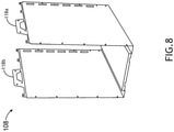
- FIG. 8 illustrates an outer cover 108 of an aircraft galley oven 102, in accordance with an example embodiment of the present disclosure.
- the outer cover 108 may be formed from a single piece of sheet metal.
- the outer cover 108 may be formed from a single piece of aluminum.
- the outer cover 108 may define at least a portion of first side surface, a second side surface, and a bottom surface of the aircraft galley oven 102.
- the outer cover 108 may include one or more faying surfaces 118.
- the outer cover 108 may include a first faying surface 118a on the first side surface of the outer cover 108, and a second faying surface 118b on the second side surface of the outer cover 108.
- the outer cover 108 may be configured to be couplable to the control unit housing 121 (e.g., base plate 122, control unit cover 130, and the like) of the control unit 120 at the first faying surface 118a and/or the second faying surface 118b.
- the outer cover 108 may include one or more holes configured to receive one or more fasteners in order to couple the outer cover 108 to various other components of the aircraft galley oven 102 (e.g., control unit housing 121, base plate 122, top cover 110, rear cover 114, and the like).
- the outer cover 108 may be powder coated in order to provide a protective coating for the outer cover 108 and the aircraft galley oven 102.
- the portions of the outer cover 108 which are to be coupled to the control unit housing 121 may not be powder coated in order to avoid introducing resistance along the grounding path.
- the base plate 122 of the control unit housing 121 is coupled to the outer cover 108 at the first faying surface 118a and the second faying surface 118b, at least portions of the first faying surface 118a and the second faying surface 118b may not be powder coated.
- portions of the outer cover 108 which are in electrical contact with the control unit housing 121 may be treated with a conductive surface finish in order to prevent corrosion, and thus prevent degradation of the grounding path.
- the first faying surface 118a and the second faying surface 118b may be treated with a conductive surface finish, while at least a portion of the remainder of the outer cover 108 may be powder coated.
- FIG. 9 illustrates an outer cover 108 of an aircraft galley oven 102 coupled to a control unit housing 121 of a control unit 120, in accordance with an example embodiment of the present disclosure.
- control unit housing 121 (e.g., base plate 122, and the like) of the control unit 120 is coupled to the outer cover 108.
- the base plate 122 may be coupled to the outer cover 108 at the first faying surface 118a and/or the second faying surface 118b.
- the control unit housing 121 (e.g., base plate 122) may be coupled to the outer cover 108 using one or more fasteners 146.
- the one or more fasteners 146a, 146b may include any fasteners known in the art including, but not limited to, one or more bolts, one or more screws, one or more pins, and the like.
- the one or more fasteners 146 may be configured to securely couple the control unit 120 to the one or more faying surfaces 118a, 118b.
- the control unit housing 121 may be coupled to the outer cover 108 (e.g., first faying surface 118a, second faying surface 118b) in such a manner as to increase and/or optimize the surface area of the surface contact between the control unit housing 121 (e.g., base plate 122) and the outer cover 108.
- increasing the surface contact between the control unit housing 121 and the outer cover 108 may facilitate coupling (e.g., capacitive coupling, conductive coupling, or the like) for the transfer of high-frequency noise (RE) from the outer cover 108 to the control unit housing 121.
- coupling e.g., capacitive coupling, conductive coupling, or the like
- radiated signals may be transferred from the outer cover 108 to the control unit housing 121 and back to the electronic components (e.g., power supply module 136) of the control unit 120 in a guided, controlled grounding path.
- one or more electronic components of the control unit 120 (“electric power source”) (e.g., power supply module 136) may be coupled to one or more operating load components 126 of the aircraft galley oven 102 via one or more conductive coupling structures including (e.g., control unit housing 121, outercover 108, conductive structural component of the aircraft galley oven 102, and the like).
- the power supply module 136 may be coupled to the control unit housing 121, and an operating load component 126 of the aircraft galley oven 102 (e.g., pump, valve, HMI, heating element, cooling element, and the like) may be directly coupled to the control unit housing 121.
- the one or more conductive coupling structures include the control unit housing 121.
- the power supply module 136 may be coupled to the control unit housing 121, an operating load component 126 of the aircraft galley oven 102 (e.g., pump, valve, motor, HMI, heating element, cooling element, and the like) may be directly coupled to the outer body 108, and the outer cover 108 may be coupled to the control unit housing 121 at the one or more faying surfaces 118.
- the one or more conductive coupling structures include the control unit housing 121 and the outer cover 108.
- the configuration of the electrical grounding/bonding path of the present disclosure may provide a number of advantages over the grounding paths of previous electronic devices, including aircraft galley inserts (e.g., aircraft galley oven 102).
- aircraft galley inserts e.g., aircraft galley oven 102
- previous aircraft galley inserts utilize a large number of components within the grounding path between electric sources and loads within the aircraft galley inserts.
- a large number of components within the grounding path leads to an undefined and uncontrolled grounding path back to the electrical source, thereby increasing the area contributing to RE and decreasing the radiated susceptibility (RS) of the aircraft galley insert.
- RS radiated susceptibility
- the grounding path of the present disclosure may include only two components along the grounding path: (1) the control unit housing 121 (e.g., base plate 122), and (2) the outer cover 108. Furthermore, the grounding path of the present disclosure may include only two surface jumps: (1) from the electronic components to the control unit housing 121 (e.g., base plate 122), and (2) from the control unit housing 121 (e.g., base plate 122) to the outer cover 108. Fewer numbers of components and surface jumps along the grounding path allow the grounding path of the present disclosure to more efficiently and effectively control, stabilize, and reduce electromagnetic emissions generated by electronic components of the aircraft galley oven 102.
- embodiments of the present disclosure are directed to the use of the outer cover 108 and control unit housing 121 to provide for short, defined, and controlled guided paths for electrical noise to return to electrical components (e.g., power supply module 136) of the control unit 120.
- previous aircraft ovens 102 utilize small contact surfaces (e.g., small surface areas) along the grounding path. These small contact surfaces limit capacitive coupling along the grounding path, and limit the efficiency of the grounding path.
- the grounding path of the present disclosure is configured to increase the contact surfaces along the grounding path (e.g., between the electronic components and the control unit housing 121, between the control unit housing 121 and the outer cover 108, and the like) in order to increase capacitive coupling along the grounding path, and to efficiently reduce the EMI noise generated by the aircraft galley oven 102.
- FIG. 10 illustrates a flowchart of a method for an optimized grounding path of an aircraft galley insert (e.g., aircraft galley oven 102), in accordance with one or more embodiments of the present disclosure, which are not covered by the appended claims.
- aircraft galley insert e.g., aircraft galley oven 102
- one or more electronic components of an aircraft galley insert are coupled to a control unit housing.
- a power supply module 136 e.g., electronic component
- the power supply module 136 may be coupled to the control unit housing 121 via any coupling mechanism known in the art including, but not limited to, capacitive coupling, conductive coupling, and the like.
- one or more operating load components of an aircraft galley insert are coupled to one or more conductive coupling structures.
- the one or more operating load components 126 may include any components configured to carry out the various functions of the aircraft galley insert including, but not limited to, a pump, a valve, a motor, an HMI, a heating element, a cooling element, and the like.
- the one or more conductive coupling structures may include, but are not limited to, the control unit housing 121, an outer cover 108, a conductive structural component (e.g., bracket, chassis, frame, mount, and the like), and the like.
- the one or more operating load components 126 may be coupled to the one or more conductive coupling structures via any coupling mechanism known in the art including, but not limited to, capacitive coupling, conductive coupling, and the like.
- the control unit housing is coupled to the one or more conductive coupling structures.
- the control unit housing 121 may be coupled to the one or more conductive coupling structures via any coupling mechanism known in the art including, but not limited to, capacitive coupling, conductive coupling, and the like.
- the one or more conductive coupling structures include the control unit housing 121 itself (e.g., the one or more operating load components 126 are coupled directly to the control unit housing 121), it is noted herein that step 1006 may not be necessary.
- the one or more electronic components are electrically coupled to the one or more operating load components via one or more electrical lines.
- the one or more electronic components e.g., power supply module 136) may be coupled to the one or more operating load components 126 via one or more electrical lines 124.
- radiated emissions produced by the one or more electronic components are transferred from the one or more conductive coupling structures to the control unit housing via at least one of a capacitive coupling or a conductive coupling between the one or more conductive coupling structures and the control unit housing.
- the radiated emissions are transferred from the control unit housing to the one or more electronic components via at least one of a capacitive coupling or a conductive coupling between the control unit housing and the one or more electronic components within the control unit housing.
- any two components herein combined to achieve a particular functionality can be seen as “associated with” each other such that the desired functionality is achieved, irrespective of architectures or intermedial components.
- any two components so associated can also be viewed as being “connected,” or “coupled,” to each other to achieve the desired functionality, and any two components capable of being so associated can also be viewed as being “couplable,” to each other to achieve the desired functionality.
- Specific examples of couplable include but are not limited to physically mateable and/or physically interacting components and/or wirelessly interactable and/or wirelessly interacting components and/or logically interacting and/or logically interactable components.
Landscapes
- Engineering & Computer Science (AREA)
- Aviation & Aerospace Engineering (AREA)
- Mechanical Engineering (AREA)
- Chemical & Material Sciences (AREA)
- Combustion & Propulsion (AREA)
- General Engineering & Computer Science (AREA)
- Microelectronics & Electronic Packaging (AREA)
- Shielding Devices Or Components To Electric Or Magnetic Fields (AREA)
- Health & Medical Sciences (AREA)
- General Health & Medical Sciences (AREA)
- Pulmonology (AREA)
Claims (11)
- Pièce rapportée de cuisine de bord d'aéronef, comprenant :une unité de commande (120) comportant un boîtier d'unité de commande (121) dans laquelle le boîtier d'unité de commande comprend une plaque de base (122) couplée à un couvercle d'unité de commande, et dans laquelle la plaque de base comprend au moins l'une parmi une structure en aluminium moulé, une structure en aluminium coulé, une structure en titane ou une structure en acier ;un ou plusieurs composants électroniques au moins partiellement contenus à l'intérieur du boîtier d'unité de commande, dans laquelle au moins un composant électronique des un ou plusieurs composants électroniques est couplé au boîtier d'unité de commande ; etun ou plusieurs composants de charge de fonctionnement (126) couplés électriquement à l'au moins un composant électronique via une ou plusieurs lignes électriques,dans laquelle le boîtier d'unité de commande est conçu pour fournir un chemin de mise à la terre pour des émissions rayonnées produites par l'au moins un composant électronique en transférant des émissions rayonnées en retour vers l'au moins un composant électronique ; et caractérisée en ce que :
la plaque de base comporte une ou plusieurs pièces d'écartement (134), dans laquelle la plaque de base est couplée à une carte de circuit imprimé (138) au niveau des une ou plusieurs pièces d'écartement ; et dans laquelle le boîtier d'unité de commande est en outre conçu pour se coupler thermiquement à l'au moins un composant électronique et dissiper la chaleur depuis l'au moins un composant électronique. - Pièce rapportée de cuisine de bord d'aéronef selon la revendication 1, dans laquelle l'au moins un composant électronique est couplé au boîtier d'unité de commande via au moins l'un parmi un couplage capacitif ou un couplage conducteur.
- Pièce rapportée de cuisine de bord d'aéronef selon la revendication 1 ou 2, comprenant en outre une ou plusieurs structures de couplage conductrices couplées au boîtier d'unité de commande, dans laquelle le boîtier d'unité de commande est conçu pour transférer des émissions rayonnées depuis les une ou plusieurs structures de couplage conductrices vers l'au moins un composant électronique.
- Pièce rapportée de cuisine de bord d'aéronef selon la revendication 3, dans laquelle les un ou plusieurs composants de charge de fonctionnement sont couplés aux une ou plusieurs structures de couplage conductrices, ou dans laquelle les un ou plusieurs composants de charge de fonctionnement sont couplés directement au boîtier d'unité de commande.
- Pièce rapportée de cuisine de bord d'aéronef selon la revendication 3, dans laquelle les une ou plusieurs structures de couplage conductrices comprennent au moins l'un parmi un couvercle extérieur ou un composant structurel conducteur.
- Pièce rapportée de cuisine de bord d'aéronef selon la revendication 5, dans laquelle le couvercle extérieur comporte une ou plusieurs surfaces de contact, dans laquelle le couvercle extérieur est couplé au boîtier d'unité de commande par au moins l'une parmi les une ou plusieurs surfaces de contact.
- Système selon la revendication 6, dans lequel les une ou plusieurs surfaces de contact sont conçues pour augmenter une zone de couplage entre le couvercle extérieur et le boîtier d'unité de commande, et/ou dans lequel les une ou plusieurs surfaces de contact sont traitées avec une finition de surface conductrice pour empêcher la corrosion.
- Pièce rapportée de cuisine de bord d'aéronef selon une quelconque revendication précédente, dans laquelle l'au moins un composant électronique comprend un module d'alimentation, et/ou dans laquelle les un ou plusieurs composants de charge de fonctionnement comprennent au moins l'un parmi une pompe, une vanne, un moteur, une interface homme-machine (IHM), un élément chauffant ou un élément de refroidissement.
- Pièce rapportée de cuisine de bord d'aéronef selon une quelconque revendication précédente, dans laquelle le boîtier d'unité de commande comporte au moins un évidement conçu pour recevoir l'au moins un composant électronique parmi les un ou plusieurs composants électroniques afin d'augmenter une zone de couplage entre le boîtier d'unité de commande et l'au moins un composant électronique.
- Pièce rapportée de cuisine de bord d'aéronef selon une quelconque revendication précédente, dans laquelle la pièce rapportée de cuisine de bord d'aéronef comprend un four de cuisine de bord d'aéronef (102).
- Pièce rapportée de cuisine de bord d'aéronef selon une quelconque revendication précédente, comprenant en outre :un corps de pièce rapportée de cuisine de bord (103) pouvant être installé dans une cuisine de bord d'un aéronef, le corps de pièce rapportée de cuisine de bord comportant un couvercle extérieur (108) ;l'unité de commande comportant le boîtier d'unité de commande couplé au couvercle extérieur ; les un ou plusieurs composants de charge de fonctionnement étant couplés en outre au couvercle extérieur,dans laquelle le boîtier d'unité de commande est conçu pour fournir le chemin de mise à la terre pour des émissions rayonnées produites par l'au moins un composant électrique en transférant des émissions rayonnées depuis le couvercle extérieur en retour vers l'au moins un composant électronique.
Applications Claiming Priority (1)
| Application Number | Priority Date | Filing Date | Title |
|---|---|---|---|
| US16/451,397 US11661196B2 (en) | 2019-06-25 | 2019-06-25 | Optimized electronics grounding path for high-frequency noise |
Publications (3)
| Publication Number | Publication Date |
|---|---|
| EP3757006A1 EP3757006A1 (fr) | 2020-12-30 |
| EP3757006B1 true EP3757006B1 (fr) | 2022-03-09 |
| EP3757006B8 EP3757006B8 (fr) | 2022-04-13 |
Family
ID=69156220
Family Applications (1)
| Application Number | Title | Priority Date | Filing Date |
|---|---|---|---|
| EP20150785.2A Active EP3757006B8 (fr) | 2019-06-25 | 2020-01-08 | Voie de mise à la terre électronique optimisée pour le bruit haute fréquence |
Country Status (2)
| Country | Link |
|---|---|
| US (1) | US11661196B2 (fr) |
| EP (1) | EP3757006B8 (fr) |
Families Citing this family (4)
| Publication number | Priority date | Publication date | Assignee | Title |
|---|---|---|---|---|
| US11661196B2 (en) | 2019-06-25 | 2023-05-30 | B/E Aerospace, Inc. | Optimized electronics grounding path for high-frequency noise |
| US12172756B2 (en) * | 2022-05-09 | 2024-12-24 | Safran Cabin Germany Gmbh | Integrated electronic panel for on-board vehicle equipment |
| EP4368508A1 (fr) * | 2022-11-11 | 2024-05-15 | B/E Aerospace, Inc. | Module de commande d'insert d'office |
| EP4371879A1 (fr) * | 2022-11-17 | 2024-05-22 | B/E Aerospace, Inc. | Insert de cuisine d'avion |
Citations (2)
| Publication number | Priority date | Publication date | Assignee | Title |
|---|---|---|---|---|
| EP0806892B1 (fr) * | 1996-05-08 | 1999-06-09 | W.L. GORE & ASSOCIATES, INC. | Cage de Faraday |
| EP2338792B1 (fr) * | 2009-12-22 | 2014-08-06 | Jamco Corporation | Système de contrôle d'une cuisine d'avion |
Family Cites Families (22)
| Publication number | Priority date | Publication date | Assignee | Title |
|---|---|---|---|---|
| US6348654B1 (en) * | 2000-10-12 | 2002-02-19 | Parker-Hannifin Corporation | Compound waveform gasket for low closure force EMI shielding applications |
| JP2002246787A (ja) | 2001-02-14 | 2002-08-30 | Matsushita Electric Ind Co Ltd | 電磁波遮蔽装置および電子レンジ |
| DE60206489T2 (de) * | 2001-05-11 | 2006-07-13 | Parker-Hannifin Corp., Cleveland | Gezahnte Dichtung für EMI-Abschirmungsanwendungen mit niedrigen Verpressungskräften |
| US6880351B2 (en) * | 2001-09-05 | 2005-04-19 | Be Intellectual Property, Inc. | Liquid galley refrigeration system for aircraft |
| US6809169B2 (en) * | 2002-06-07 | 2004-10-26 | The Boeing Company | Polysiloxane coatings for surfaces |
| US6972967B2 (en) * | 2003-02-20 | 2005-12-06 | Avaya Technology Group | EMC/ESD mitigation module |
| US7829825B2 (en) * | 2003-05-23 | 2010-11-09 | Koninklijke Fabriek Inventum B.V. | Oven and its combination with a steam module |
| NL1024564C2 (nl) * | 2003-10-17 | 2005-04-20 | Konink Fabriek Inventum B V | Oven, in het bijzonder voor toepassing in een vliegtuig, met een door een gelijkstroommotor aangedreven ventilator. |
| US7529092B2 (en) * | 2004-04-15 | 2009-05-05 | Thomson Licensing | Electromagnetic interference shield and heat sink apparatus |
| US7889515B2 (en) * | 2008-02-15 | 2011-02-15 | Laird Technologies, Inc. | EMI shielding assemblies and related methods of retaining components thereof together |
| US9238398B2 (en) * | 2008-09-25 | 2016-01-19 | B/E Aerospace, Inc. | Refrigeration systems and methods for connection with a vehicle's liquid cooling system |
| DE102008064070B4 (de) * | 2008-12-19 | 2011-01-13 | Airbus Operations Gmbh | Bordküchenofen zur Zubereitung von Speisen an Bord eines Flugzeugs |
| US9188380B2 (en) * | 2011-08-23 | 2015-11-17 | B/E Aerospace, Inc. | Aircraft galley liquid cooling system |
| CN104487343A (zh) * | 2012-03-28 | 2015-04-01 | B/E航空公司 | 具有可滑动抽屉机构的烤箱 |
| CN104379449B (zh) * | 2012-03-28 | 2016-10-26 | B/E航空公司 | 有收合式门的挂式厨房插件和包括挂式厨房插件的厨房 |
| CA2867157C (fr) * | 2012-03-29 | 2017-01-24 | B/E Aerospace, Inc. | Four de vehicule ayant un flux d'air optimise |
| US9038945B2 (en) * | 2013-03-15 | 2015-05-26 | B/E Aerospace, Inc. | Integrated aircraft galley system |
| US9566921B2 (en) * | 2013-06-18 | 2017-02-14 | B/E Aerospace, Inc. | Appliance insert connection interface for an aircraft galley |
| US9676483B2 (en) * | 2013-07-03 | 2017-06-13 | B/E Aerospace, Inc. | Aircraft galley air chiller system |
| US10059454B2 (en) * | 2015-07-30 | 2018-08-28 | B/E Aerospace, Inc. | Aircraft galley plumbing system |
| US10032693B2 (en) * | 2015-10-20 | 2018-07-24 | General Electric Company | Heat transfer chassis and method for forming the same |
| US11661196B2 (en) | 2019-06-25 | 2023-05-30 | B/E Aerospace, Inc. | Optimized electronics grounding path for high-frequency noise |
-
2019
- 2019-06-25 US US16/451,397 patent/US11661196B2/en active Active
-
2020
- 2020-01-08 EP EP20150785.2A patent/EP3757006B8/fr active Active
Patent Citations (2)
| Publication number | Priority date | Publication date | Assignee | Title |
|---|---|---|---|---|
| EP0806892B1 (fr) * | 1996-05-08 | 1999-06-09 | W.L. GORE & ASSOCIATES, INC. | Cage de Faraday |
| EP2338792B1 (fr) * | 2009-12-22 | 2014-08-06 | Jamco Corporation | Système de contrôle d'une cuisine d'avion |
Also Published As
| Publication number | Publication date |
|---|---|
| EP3757006B8 (fr) | 2022-04-13 |
| EP3757006A1 (fr) | 2020-12-30 |
| US11661196B2 (en) | 2023-05-30 |
| US20210291986A1 (en) | 2021-09-23 |
Similar Documents
| Publication | Publication Date | Title |
|---|---|---|
| EP3757006B1 (fr) | Voie de mise à la terre électronique optimisée pour le bruit haute fréquence | |
| KR100730605B1 (ko) | 전자부품 조립체용 컨포밍 실드 폼, 그 제조 방법 및 이용방법 | |
| US8059409B2 (en) | Avionics chassis | |
| US8222541B2 (en) | Avionics chassis | |
| US7911796B2 (en) | Avionics chassis | |
| US8023267B2 (en) | Avionics chassis | |
| EP3684154B1 (fr) | Élément d'insert thermoconducteur pour unité électronique | |
| US6944025B2 (en) | EMI shielding apparatus | |
| CN109728419A (zh) | 天线组件和电子设备 | |
| CN208904980U (zh) | 无线通信组件、遥控器及飞行器 | |
| EP3892547A1 (fr) | Ensemble de commande et aéronef | |
| CN101498960A (zh) | 一种制造具有良好电磁兼容性能的计算机的方法 | |
| CN105813376A (zh) | 一种pcb防断板铣镀槽及其应用方法 | |
| CN212148678U (zh) | 一种应用于新能源汽车的智能座舱主机结构 | |
| CN204425843U (zh) | 导航接收机机箱 | |
| CN108052171A (zh) | 一种平板式加固一体机 | |
| US9417670B2 (en) | High power dissipation mezzanine card cooling frame | |
| CN211019721U (zh) | Pcba组件及电焰灶 | |
| CN206100686U (zh) | 一种atr机箱的电源盒 | |
| CN207166928U (zh) | 一种抗干扰航空程序控制电源箱 | |
| CN219428368U (zh) | 一种arinc600标准机箱托架结构 | |
| CN207235302U (zh) | 一种模块化集成航空程序控制电源箱 | |
| CN106255371B (zh) | 一种atr机箱的电源盒 | |
| CN106469971A (zh) | 新型开关电源 | |
| CN202075664U (zh) | 一种多功能服务器 |
Legal Events
| Date | Code | Title | Description |
|---|---|---|---|
| PUAI | Public reference made under article 153(3) epc to a published international application that has entered the european phase |
Free format text: ORIGINAL CODE: 0009012 |
|
| STAA | Information on the status of an ep patent application or granted ep patent |
Free format text: STATUS: THE APPLICATION HAS BEEN PUBLISHED |
|
| AK | Designated contracting states |
Kind code of ref document: A1 Designated state(s): AL AT BE BG CH CY CZ DE DK EE ES FI FR GB GR HR HU IE IS IT LI LT LU LV MC MK MT NL NO PL PT RO RS SE SI SK SM TR |
|
| AX | Request for extension of the european patent |
Extension state: BA ME |
|
| STAA | Information on the status of an ep patent application or granted ep patent |
Free format text: STATUS: REQUEST FOR EXAMINATION WAS MADE |
|
| 17P | Request for examination filed |
Effective date: 20210630 |
|
| RBV | Designated contracting states (corrected) |
Designated state(s): AL AT BE BG CH CY CZ DE DK EE ES FI FR GB GR HR HU IE IS IT LI LT LU LV MC MK MT NL NO PL PT RO RS SE SI SK SM TR |
|
| GRAP | Despatch of communication of intention to grant a patent |
Free format text: ORIGINAL CODE: EPIDOSNIGR1 |
|
| STAA | Information on the status of an ep patent application or granted ep patent |
Free format text: STATUS: GRANT OF PATENT IS INTENDED |
|
| INTG | Intention to grant announced |
Effective date: 20210927 |
|
| RAP3 | Party data changed (applicant data changed or rights of an application transferred) |
Owner name: KONINKLIJKE FABRIEK INVENTUM B.V. |
|
| GRAS | Grant fee paid |
Free format text: ORIGINAL CODE: EPIDOSNIGR3 |
|
| GRAA | (expected) grant |
Free format text: ORIGINAL CODE: 0009210 |
|
| STAA | Information on the status of an ep patent application or granted ep patent |
Free format text: STATUS: THE PATENT HAS BEEN GRANTED |
|
| AK | Designated contracting states |
Kind code of ref document: B1 Designated state(s): AL AT BE BG CH CY CZ DE DK EE ES FI FR GB GR HR HU IE IS IT LI LT LU LV MC MK MT NL NO PL PT RO RS SE SI SK SM TR |
|
| REG | Reference to a national code |
Ref country code: CH Ref legal event code: EP Ref country code: AT Ref legal event code: REF Ref document number: 1473957 Country of ref document: AT Kind code of ref document: T Effective date: 20220315 |
|
| REG | Reference to a national code |
Ref country code: IE Ref legal event code: FG4D |
|
| REG | Reference to a national code |
Ref country code: CH Ref legal event code: PK Free format text: BERICHTIGUNG B8 Ref country code: DE Ref legal event code: R096 Ref document number: 602020002069 Country of ref document: DE |
|
| REG | Reference to a national code |
Ref country code: DE Ref legal event code: R081 Ref document number: 602020002069 Country of ref document: DE Owner name: B/E AEROSPACE, INC., WINSTON SALEM, US Free format text: FORMER OWNER: KONINKLIJKE FABRIEK INVENTUM B.V., NIEUWEGEIN, NL |
|
| RAP2 | Party data changed (patent owner data changed or rights of a patent transferred) |
Owner name: B/E AEROSPACE, INC. |
|
| REG | Reference to a national code |
Ref country code: NL Ref legal event code: FP |
|
| REG | Reference to a national code |
Ref country code: LT Ref legal event code: MG9D |
|
| PG25 | Lapsed in a contracting state [announced via postgrant information from national office to epo] |
Ref country code: SE Free format text: LAPSE BECAUSE OF FAILURE TO SUBMIT A TRANSLATION OF THE DESCRIPTION OR TO PAY THE FEE WITHIN THE PRESCRIBED TIME-LIMIT Effective date: 20220309 Ref country code: RS Free format text: LAPSE BECAUSE OF FAILURE TO SUBMIT A TRANSLATION OF THE DESCRIPTION OR TO PAY THE FEE WITHIN THE PRESCRIBED TIME-LIMIT Effective date: 20220309 Ref country code: NO Free format text: LAPSE BECAUSE OF FAILURE TO SUBMIT A TRANSLATION OF THE DESCRIPTION OR TO PAY THE FEE WITHIN THE PRESCRIBED TIME-LIMIT Effective date: 20220609 Ref country code: LT Free format text: LAPSE BECAUSE OF FAILURE TO SUBMIT A TRANSLATION OF THE DESCRIPTION OR TO PAY THE FEE WITHIN THE PRESCRIBED TIME-LIMIT Effective date: 20220309 Ref country code: HR Free format text: LAPSE BECAUSE OF FAILURE TO SUBMIT A TRANSLATION OF THE DESCRIPTION OR TO PAY THE FEE WITHIN THE PRESCRIBED TIME-LIMIT Effective date: 20220309 Ref country code: BG Free format text: LAPSE BECAUSE OF FAILURE TO SUBMIT A TRANSLATION OF THE DESCRIPTION OR TO PAY THE FEE WITHIN THE PRESCRIBED TIME-LIMIT Effective date: 20220609 |
|
| REG | Reference to a national code |
Ref country code: AT Ref legal event code: MK05 Ref document number: 1473957 Country of ref document: AT Kind code of ref document: T Effective date: 20220309 |
|
| PG25 | Lapsed in a contracting state [announced via postgrant information from national office to epo] |
Ref country code: LV Free format text: LAPSE BECAUSE OF FAILURE TO SUBMIT A TRANSLATION OF THE DESCRIPTION OR TO PAY THE FEE WITHIN THE PRESCRIBED TIME-LIMIT Effective date: 20220309 Ref country code: GR Free format text: LAPSE BECAUSE OF FAILURE TO SUBMIT A TRANSLATION OF THE DESCRIPTION OR TO PAY THE FEE WITHIN THE PRESCRIBED TIME-LIMIT Effective date: 20220610 Ref country code: FI Free format text: LAPSE BECAUSE OF FAILURE TO SUBMIT A TRANSLATION OF THE DESCRIPTION OR TO PAY THE FEE WITHIN THE PRESCRIBED TIME-LIMIT Effective date: 20220309 |
|
| PG25 | Lapsed in a contracting state [announced via postgrant information from national office to epo] |
Ref country code: SM Free format text: LAPSE BECAUSE OF FAILURE TO SUBMIT A TRANSLATION OF THE DESCRIPTION OR TO PAY THE FEE WITHIN THE PRESCRIBED TIME-LIMIT Effective date: 20220309 Ref country code: SK Free format text: LAPSE BECAUSE OF FAILURE TO SUBMIT A TRANSLATION OF THE DESCRIPTION OR TO PAY THE FEE WITHIN THE PRESCRIBED TIME-LIMIT Effective date: 20220309 Ref country code: RO Free format text: LAPSE BECAUSE OF FAILURE TO SUBMIT A TRANSLATION OF THE DESCRIPTION OR TO PAY THE FEE WITHIN THE PRESCRIBED TIME-LIMIT Effective date: 20220309 Ref country code: PT Free format text: LAPSE BECAUSE OF FAILURE TO SUBMIT A TRANSLATION OF THE DESCRIPTION OR TO PAY THE FEE WITHIN THE PRESCRIBED TIME-LIMIT Effective date: 20220711 Ref country code: ES Free format text: LAPSE BECAUSE OF FAILURE TO SUBMIT A TRANSLATION OF THE DESCRIPTION OR TO PAY THE FEE WITHIN THE PRESCRIBED TIME-LIMIT Effective date: 20220309 Ref country code: EE Free format text: LAPSE BECAUSE OF FAILURE TO SUBMIT A TRANSLATION OF THE DESCRIPTION OR TO PAY THE FEE WITHIN THE PRESCRIBED TIME-LIMIT Effective date: 20220309 Ref country code: CZ Free format text: LAPSE BECAUSE OF FAILURE TO SUBMIT A TRANSLATION OF THE DESCRIPTION OR TO PAY THE FEE WITHIN THE PRESCRIBED TIME-LIMIT Effective date: 20220309 Ref country code: AT Free format text: LAPSE BECAUSE OF FAILURE TO SUBMIT A TRANSLATION OF THE DESCRIPTION OR TO PAY THE FEE WITHIN THE PRESCRIBED TIME-LIMIT Effective date: 20220309 |
|
| PG25 | Lapsed in a contracting state [announced via postgrant information from national office to epo] |
Ref country code: PL Free format text: LAPSE BECAUSE OF FAILURE TO SUBMIT A TRANSLATION OF THE DESCRIPTION OR TO PAY THE FEE WITHIN THE PRESCRIBED TIME-LIMIT Effective date: 20220309 Ref country code: IS Free format text: LAPSE BECAUSE OF FAILURE TO SUBMIT A TRANSLATION OF THE DESCRIPTION OR TO PAY THE FEE WITHIN THE PRESCRIBED TIME-LIMIT Effective date: 20220709 Ref country code: AL Free format text: LAPSE BECAUSE OF FAILURE TO SUBMIT A TRANSLATION OF THE DESCRIPTION OR TO PAY THE FEE WITHIN THE PRESCRIBED TIME-LIMIT Effective date: 20220309 |
|
| REG | Reference to a national code |
Ref country code: DE Ref legal event code: R097 Ref document number: 602020002069 Country of ref document: DE |
|
| PLBE | No opposition filed within time limit |
Free format text: ORIGINAL CODE: 0009261 |
|
| STAA | Information on the status of an ep patent application or granted ep patent |
Free format text: STATUS: NO OPPOSITION FILED WITHIN TIME LIMIT |
|
| PG25 | Lapsed in a contracting state [announced via postgrant information from national office to epo] |
Ref country code: DK Free format text: LAPSE BECAUSE OF FAILURE TO SUBMIT A TRANSLATION OF THE DESCRIPTION OR TO PAY THE FEE WITHIN THE PRESCRIBED TIME-LIMIT Effective date: 20220309 |
|
| 26N | No opposition filed |
Effective date: 20221212 |
|
| PG25 | Lapsed in a contracting state [announced via postgrant information from national office to epo] |
Ref country code: SI Free format text: LAPSE BECAUSE OF FAILURE TO SUBMIT A TRANSLATION OF THE DESCRIPTION OR TO PAY THE FEE WITHIN THE PRESCRIBED TIME-LIMIT Effective date: 20220309 |
|
| PG25 | Lapsed in a contracting state [announced via postgrant information from national office to epo] |
Ref country code: IT Free format text: LAPSE BECAUSE OF FAILURE TO SUBMIT A TRANSLATION OF THE DESCRIPTION OR TO PAY THE FEE WITHIN THE PRESCRIBED TIME-LIMIT Effective date: 20220309 |
|
| REG | Reference to a national code |
Ref country code: CH Ref legal event code: PL |
|
| PG25 | Lapsed in a contracting state [announced via postgrant information from national office to epo] |
Ref country code: LU Free format text: LAPSE BECAUSE OF NON-PAYMENT OF DUE FEES Effective date: 20230108 |
|
| REG | Reference to a national code |
Ref country code: BE Ref legal event code: MM Effective date: 20230131 |
|
| PG25 | Lapsed in a contracting state [announced via postgrant information from national office to epo] |
Ref country code: LI Free format text: LAPSE BECAUSE OF NON-PAYMENT OF DUE FEES Effective date: 20230131 Ref country code: CH Free format text: LAPSE BECAUSE OF NON-PAYMENT OF DUE FEES Effective date: 20230131 |
|
| PG25 | Lapsed in a contracting state [announced via postgrant information from national office to epo] |
Ref country code: BE Free format text: LAPSE BECAUSE OF NON-PAYMENT OF DUE FEES Effective date: 20230131 |
|
| PG25 | Lapsed in a contracting state [announced via postgrant information from national office to epo] |
Ref country code: IE Free format text: LAPSE BECAUSE OF NON-PAYMENT OF DUE FEES Effective date: 20230108 |
|
| PG25 | Lapsed in a contracting state [announced via postgrant information from national office to epo] |
Ref country code: MC Free format text: LAPSE BECAUSE OF FAILURE TO SUBMIT A TRANSLATION OF THE DESCRIPTION OR TO PAY THE FEE WITHIN THE PRESCRIBED TIME-LIMIT Effective date: 20220309 |
|
| PG25 | Lapsed in a contracting state [announced via postgrant information from national office to epo] |
Ref country code: MC Free format text: LAPSE BECAUSE OF FAILURE TO SUBMIT A TRANSLATION OF THE DESCRIPTION OR TO PAY THE FEE WITHIN THE PRESCRIBED TIME-LIMIT Effective date: 20220309 |
|
| PG25 | Lapsed in a contracting state [announced via postgrant information from national office to epo] |
Ref country code: CY Free format text: LAPSE BECAUSE OF FAILURE TO SUBMIT A TRANSLATION OF THE DESCRIPTION OR TO PAY THE FEE WITHIN THE PRESCRIBED TIME-LIMIT; INVALID AB INITIO Effective date: 20200108 |
|
| PG25 | Lapsed in a contracting state [announced via postgrant information from national office to epo] |
Ref country code: HU Free format text: LAPSE BECAUSE OF FAILURE TO SUBMIT A TRANSLATION OF THE DESCRIPTION OR TO PAY THE FEE WITHIN THE PRESCRIBED TIME-LIMIT; INVALID AB INITIO Effective date: 20200108 |
|
| PG25 | Lapsed in a contracting state [announced via postgrant information from national office to epo] |
Ref country code: TR Free format text: LAPSE BECAUSE OF FAILURE TO SUBMIT A TRANSLATION OF THE DESCRIPTION OR TO PAY THE FEE WITHIN THE PRESCRIBED TIME-LIMIT Effective date: 20220309 |
|
| PGFP | Annual fee paid to national office [announced via postgrant information from national office to epo] |
Ref country code: GB Payment date: 20251220 Year of fee payment: 7 |
|
| PGFP | Annual fee paid to national office [announced via postgrant information from national office to epo] |
Ref country code: NL Payment date: 20251217 Year of fee payment: 7 Ref country code: FR Payment date: 20251217 Year of fee payment: 7 |
|
| P01 | Opt-out of the competence of the unified patent court (upc) registered |
Free format text: CASE NUMBER: UPC_APP_0018863_3757006/2025 Effective date: 20251222 |
|
| PGFP | Annual fee paid to national office [announced via postgrant information from national office to epo] |
Ref country code: DE Payment date: 20251217 Year of fee payment: 7 |