EP3760772B1 - Optimierung des betriebes einer spinnmaschine - Google Patents
Optimierung des betriebes einer spinnmaschine Download PDFInfo
- Publication number
- EP3760772B1 EP3760772B1 EP20179126.6A EP20179126A EP3760772B1 EP 3760772 B1 EP3760772 B1 EP 3760772B1 EP 20179126 A EP20179126 A EP 20179126A EP 3760772 B1 EP3760772 B1 EP 3760772B1
- Authority
- EP
- European Patent Office
- Prior art keywords
- yarn
- control device
- parameter
- production speed
- specified
- Prior art date
- Legal status (The legal status is an assumption and is not a legal conclusion. Google has not performed a legal analysis and makes no representation as to the accuracy of the status listed.)
- Active
Links
Images


Classifications
-
- D—TEXTILES; PAPER
- D01—NATURAL OR MAN-MADE THREADS OR FIBRES; SPINNING
- D01H—SPINNING OR TWISTING
- D01H1/00—Spinning or twisting machines in which the product is wound-up continuously
- D01H1/14—Details
- D01H1/20—Driving or stopping arrangements
-
- D—TEXTILES; PAPER
- D01—NATURAL OR MAN-MADE THREADS OR FIBRES; SPINNING
- D01H—SPINNING OR TWISTING
- D01H4/00—Open-end spinning machines or arrangements for imparting twist to independently moving fibres separated from slivers; Piecing arrangements therefor; Covering endless core threads with fibres by open-end spinning techniques
- D01H4/42—Control of driving or stopping
- D01H4/44—Control of driving or stopping in rotor spinning
-
- D—TEXTILES; PAPER
- D01—NATURAL OR MAN-MADE THREADS OR FIBRES; SPINNING
- D01H—SPINNING OR TWISTING
- D01H13/00—Other common constructional features, details or accessories
- D01H13/14—Warning or safety devices, e.g. automatic fault detectors, stop motions ; Monitoring the entanglement of slivers in drafting arrangements
- D01H13/22—Warning or safety devices, e.g. automatic fault detectors, stop motions ; Monitoring the entanglement of slivers in drafting arrangements responsive to presence of irregularities in running material
-
- D—TEXTILES; PAPER
- D01—NATURAL OR MAN-MADE THREADS OR FIBRES; SPINNING
- D01H—SPINNING OR TWISTING
- D01H13/00—Other common constructional features, details or accessories
- D01H13/32—Counting, measuring, recording or registering devices
-
- D—TEXTILES; PAPER
- D01—NATURAL OR MAN-MADE THREADS OR FIBRES; SPINNING
- D01H—SPINNING OR TWISTING
- D01H4/00—Open-end spinning machines or arrangements for imparting twist to independently moving fibres separated from slivers; Piecing arrangements therefor; Covering endless core threads with fibres by open-end spinning techniques
- D01H4/42—Control of driving or stopping
Definitions
- the present invention relates to a method for optimizing the operation of a spinning machine, in particular an open-end rotor spinning machine or an air jet spinning machine, in terms of quality and productivity.
- the invention also relates to a device comprising a control device and the spinning machine.
- the EP 2 565 306 B1 discloses an open-end rotor spinning machine in which the speed of the spinning rotors is automatically set depending on a determined thread breakage rate and the thread breakage rate is thereby regulated so that the thread breakage rate is in a specified target range below a maximum thread breakage rate.
- the speed of the spinning rotor directly determines the production speed of the open-end rotor spinning machine.
- the thread take-off speed and the feed speed of the fiber sliver are changed according to the speed of the spinning rotor.
- the yarn In rotor spinning, the yarn is formed in the rotor groove of the spinning rotor.
- the deposited fibers are given rotation due to the torsional moment of the rotating yarn end. This rotation creates the yarn strength required for the yarn draw-off.
- the thread When the yarn is drawn out of the rotor groove, the thread must have a strength that is greater than the centrifugal force in the rotor generated by the yarn circulation. Otherwise, the thread would break in the area of the rotor. With an almost constant breaking force, the centrifugal force of the rotating yarn end increases quadratically as the rotor speed increases. Doubling the rotor speed therefore leads to four times the thread tension in the area of the rotor. The risk of thread breakage in the area of the rotor therefore increases with increasing rotor speed.
- the yarn breakage rate that can be accepted when operating an open-end rotor spinning machine depends on the number of means available to remedy yarn breakage.
- the yarn breakage rate is the number of yarn breaks in relation to the operating time of the open-end rotor spinning machine or a work station.
- the yarn breakage is remedied by a piecing machine.
- Piecing can be semi-automatic, which means that an operator is required for piecing.
- Piecing can also be carried out automatically using a piecing carriage. There are also machines where piecing can be carried out automatically at a work station. In the first In the first case, the number of acceptable thread breaks depends on the number of operators available. In the second case, the permissible thread break rate is determined by the number of piecing carriages. In the case of autonomous piecing at the work stations, it is important how many piecings can be carried out in parallel without affecting an adequate vacuum supply. Based on the conditions described, a maximum permissible number of thread breaks can be specified.
- the speed at which the yarn is produced and thus the productivity of the open-end rotor spinning machine increases with increasing rotor speed. It is therefore desirable that the spinning rotors are operated at the maximum possible speed.
- the EN 10 2004 053 505 A1 discloses a method for optimizing the productivity of an air jet spinning machine by reducing the production speed when the number of thread breaks increases and increasing it when the number of thread breaks decreases.
- the production speed is adjusted depending on the thread breakage rate.
- the delivery speed and the take-off speed are adjusted accordingly.
- the compressed air is adjusted accordingly depending on the production speed.
- the WO 2018/101240 A1 discloses a method for optimizing a winding machine in conjunction with a spinning machine.
- the US 5 551 223 A discloses a method for optimizing the spinning geometry of a ring spinning machine, wherein the spinning geometry and the spindle speed are influenced such that the yarn breakage rate and the spinning tension are within a predetermined range.
- Yarn cleaners record measurable properties of the yarn during production. This is intended to identify yarn defects. A cleaning limit can be used to determine which yarn defects are cleaned out and which remain in the yarn. In addition to cleaning out yarn defects, the yarn cleaner also enables the quality of the yarn to be assessed.
- the object of the present invention is to optimize both productivity and quality in yarn production.
- the object is achieved by a method for optimizing the operation of a spinning machine in terms of quality and productivity.
- a yarn with predetermined yarn properties is produced, a quality parameter of the yarn is recorded during spinning, a parameter for setting the production speed is specified, the quality parameter and the parameter for setting the production speed are evaluated and the production speed is set depending on a target variable, wherein the target variable includes the quality parameter.
- the optimization is preferably carried out for an open-end rotor spinning machine or for an air-jet spinning machine.
- the yarn properties include yarn fineness and yarn twist.
- the raw material used also influences the yarn properties.
- the yarn properties can preferably also be specified by machine and/or production parameters. These include in particular the spinning equipment, such as spinning rotors, opening rollers and take-off nozzles or spinnerets.
- the spinning vacuum or spinning pressure, the draft given by the spinning device and the twist given also play a role.
- the open-end rotor spinning machine the ratio of take-off speed, fiber sliver feed and rotor speed is important.
- the air jet spinning machine it is the ratio of spinning pressure and delivery speed.
- the CV value and/or IPI values are particularly preferred for optimizing yarn production.
- the CV value is a measure of the evenness of the yarn; the more uneven the yarn, the higher the CV value.
- the IPI values are so-called common yarn defects (imperfections) that are not considered to be disruptive when viewed individually. They are mostly below the cleaning range activated in the short defect matrix. IPI values can be specified for thick spots, thin spots and NEPs.
- the rotor speed is the main parameter for setting the production speed on an open-end rotor spinning machine.
- the feed and take-off speed must then be adjusted accordingly.
- the parameter for setting the production speed the delivery speed can be selected.
- the spinning pressure is adjusted to the delivery speed in order to maintain the yarn properties.
- the invention is based on the knowledge that the production speed of the spinning machine has a direct influence on the quality of the yarn produced. As the production speed increases, the quality of the yarn produced decreases. By adjusting the production speed depending on a quality parameter, maximum productivity can be achieved while maintaining a desired quality. To further increase productivity, the limits for the quality parameter can be adjusted.
- the optimization can be carried out for the entire spinning machine, i.e. all workstations are operated at the same production speed.
- the setting is then preferably made based on average values or based on the evaluation of the production speed and quality parameters at a pilot spinning station. It is also possible to optimize each workstation individually. This requires self-sufficient workstations that are equipped with individual drives. Each workstation can produce at its own individual production speed. This means that each workstation can be given different limits for the quality parameters and different yarn properties. Groups of workstations on which yarns with the same yarn properties are produced can also be combined for optimization.
- the production speed is adjusted using a control device depending on a target variable, wherein the target variable includes the quality parameter.
- the control device can preferably be equipped with artificial intelligence.
- a device which has a control device and a spinning machine.
- the device comprises means for producing a yarn with predetermined yarn properties, means for detecting a quality parameter of the yarn during spinning and means for specifying a parameter for setting the production speed.
- the control device is designed to evaluate the quality parameter and the parameter for setting the production speed and the control device is designed such that the setting of the production speed is carried out with the aid of the Control device can be carried out depending on a target variable, wherein the target variable includes the quality parameter.
- the control device can be part of the spinning machine and in this case is preferably designed as a central control device and/or workstation control.
- the integrated control device preferably also takes on the known control functions of a spinning machine.
- the control device can also be (spatially) independent of the spinning machine. It is only necessary that the required data can be exchanged between the control device and the spinning machine.
- the control device can be connected to the spinning machine via a network.
- the control device can then also be connected to other spinning machines in the spinning mill for optimization purposes.
- the control device can preferably be designed as a PC, laptop or tablet or include these.
- the means for producing a yarn are preferably designed as a spinning device, in particular as an open-end rotor spinning device or air jet spinning device.
- the means for detecting a quality parameter of the yarn are preferably designed as a yarn cleaner.
- An operating device can be provided for specifying a parameter for setting the production speed.
- the thread breakage rate is recorded and evaluated and the target variable includes the thread breakage rate.
- the target variable therefore includes both the quality parameter and the thread breakage rate.
- the production speed is set both as a function of the quality parameter and as a function of the thread breakage rate.
- the production speed is preferably set so that both the quality parameter and the thread breakage rate are within predetermined limits. In this way, both productivity and quality can be optimally adjusted. This ensures that the production speed is only high enough that any thread breaks that occur can still be remedied.
- the production speed is also limited so that the quality parameter remains within the predetermined limits.
- an advantageous embodiment of the device according to the invention has means for detecting the thread breakage rate, the control device is designed to evaluate the thread breakage rate and the target value comprises the thread breakage rate.
- Thread breaks can be determined in a manner known per se with the aid of thread monitors or also with the aid of yarn cleaners.
- a corresponding evaluation device evaluates the thread breaks and determines the thread breakage rate.
- the evaluation device can also be part of the control device.
- the control device comprises a user interface on which the parameter for setting the production speed and the target size are displayed simultaneously.
- the parameter for setting the production speed is displayed on the user interface.
- the parameter for setting the production speed can also be changed via the same user interface. The operator thus receives all the relevant information that he needs to set the production speed.
- the user interface thus simplifies the setting for the operator.
- the user interface can be part of an operating device of the spinning machine or can be the screen of a PC, laptop or tablet.
- a particularly clear representation of the time course of the parameter for setting the production speed and the target size on the user interface is provided. This allows the operator to easily see how changes in the production speed affect the target size and decide whether the production speed can be increased or should be reduced.
- a limit value for the target value can be specified for the control device.
- an upper and a lower limit value for the quality parameter is specified or can be specified by the control device.
- the upper limit value is particularly important.
- the limit value(s) are also displayed on the user interface. It is also advantageous to display the limit value(s) in the display of the time course.
- control device is designed to control the production speed or the parameter for Automatically change the production speed setting depending on the deviation of the target value from the specified limit
- the control device can preferably be designed to determine suggestions for changing the parameter for setting the production speed.
- the suggestions are determined depending on the deviation of the target value from the specified limit value.
- the respective suggestion is preferably displayed to the operator on the user interface. The operator can then, in conjunction with a corresponding design of the control device, confirm the suggestion or change it manually and only then confirm it. Only after confirmation is the change in the production speed carried out by the control device.
- the control device is designed to create and save data sets that include the specified yarn properties, the parameter for setting the production speed and the associated target value.
- the control system preferably has a connection to the Internet. This means that not only local data sets are available, but also data sets from other spinning mills. This means that the case basis can be significantly increased and the learning of the system accelerated.
- control device is preferably designed to compare the data sets with the specified yarn properties and a specified limit value for the target size and to select a data set for operating the spinning machine depending on the comparison.
- the device is preferably designed to use the selected data set. This means that a data set is preferably selected by comparison and the spinning machine is preferably operated on the basis of the selected data.
- control device has an interface for revising the selected data set.
- the control device is preferably designed to apply and store the revised data set. This allows the data set to be reviewed and the case base to be expanded subsequently.
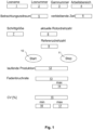
- the Fig.1 shows a user interface of a control device with the help of which the operator of the spinning machine can set the production speed depending on a target value.
- the target value includes a quality parameter, namely a CV value, and the yarn break rate.
- the CV value is given in %.
- the exemplary embodiment relates to an open-end rotor spinning machine.
- the user interface initially contains information that allows conclusions to be drawn about the yarn properties.
- Field 1 shows the batch name
- field 2 the batch number
- field 3 the yarn number
- field 4 the work area.
- the work area indicates the spinning positions for which the optimization is carried out.
- field 5 the observation time to be used for optimization can be specified. The remaining time is specified in field 6.
- a reference speed for the spinning rotor can be specified.
- a step size (Delta Rotor Speed) can be specified with which the rotor speed is changed for optimization.
- the upper limit (max) for the thread breakage rate is specified.
- Field 16 allows the entry of a lower limit (min) for the CV value.
- the upper limit (max) of the CV value is specified.
- the optimization process is started by pressing the start button 10.
- the process can be interrupted or ended using the stop button 11.
- the spinning machine initially starts operating at the reference speed 9.
- the current rotor speed is shown in field 8.
- the current production is shown in field 12. This means that the meters of yarn produced are shown.
- the current thread breakage rate 13 and the CV value 15 are also shown.
- the specified limit values are shown directly adjacent. The operator can now see at a glance whether and how far the thread breakage rate 13 and the CV value 15 are from the limits.
- the operator can now change the rotor speed directly via the reference speed 9 or by pressing a button by the previously specified step size 7.
- control device is designed to make suggestions for changing the rotor speed. Such suggestions can be displayed, for example, via a pop-up window.
- An algorithm can be stored in the control device that calculates this suggestion based on the deviation of the thread breakage rate 13 and the CV value 15 from the specified limit values 14, 16, 17 and the step size 7. The operator has the opportunity to check the suggestion again before the change in the rotor speed is carried out.
- Fig. 2 shows such a graphical representation again using the example of an open-end rotor spinning machine.
- a CV value is shown as the target value.
- the Fig. 2 shows the curve 20 of the CV value and the curve 21 of the rotor speed over time (Time).
- the lower limit 18 and the upper limit 19 for the CV value are also shown.
- the CV value is within the specified limits, but only just above the lower limit 18. This means that there is the possibility of increasing the rotor speed and increasing productivity.
- the rotor speed is increased in several steps.
- the CV value increases until the upper limit 19 is exceeded.
- the rotor speed is reduced again by the last step carried out. This means that an optimized operating point has been found that has a higher production speed. However, the CV value is still within the specified limits.
- the Fig.3 illustrates an optimization of the operation of a spinning machine in terms of quality and productivity using the principle of case-based closure.
- the process is largely automatic and is carried out by the control device according to the invention, which includes, for example, a chip with artificial intelligence.
- the starting point for the optimization is a case base or a database 22.
- This database 22 contains a large number of data sets 23 with optimized operating points of one or more spinning machines under specified conditions.
- the data sets 23 also contain the specified yarn properties, the parameter for setting the production speed and the resulting target value.
- Reference number 24 defines specified conditions under which the operation of a spinning machine is to be optimized.
- the specified conditions 24 include at least the specified yarn properties and a specified limit value for the target value.
- the conditions 24 are then compared with the data sets 23 and the data set 22 that comes closest to the conditions 24 is selected (retrieve). This results in data set 25. By applying this data set 25 under the specified conditions, the applied data set 26 is obtained (reuse).
- the method described is preferably carried out automatically by the control device.
- the control device preferably has an interface that enables revision by the operator (revise). This produces data set 27, which is then retained in the database 22 as data set 28. This allows the control system to learn and to access a larger database 22 for future
Landscapes
- Engineering & Computer Science (AREA)
- Mechanical Engineering (AREA)
- Textile Engineering (AREA)
- Spinning Or Twisting Of Yarns (AREA)
- Filamentary Materials, Packages, And Safety Devices Therefor (AREA)
Description
- Die vorliegende Erfindung betrifft ein Verfahren zur Optimierung des Betriebes einer Spinnmaschine, insbesondere einer Offenend-Rotorspinnmaschine oder einer Luftdüsenspinnmaschine, in Bezug auf Qualität und Produktivität. Die Erfindung betrifft außerdem eine Vorrichtung umfassend eine Steuereinrichtung und die Spinnmaschine.
- Die
EP 2 565 306 B1 offenbart eine Offenend-Rotorspinnmaschine, bei die Drehzahl der Spinnrotoren automatisch in Abhängigkeit von einer jeweils ermittelten Fadenbruchrate eingestellt wird und dadurch die Fadenbruchrate so geregelt wird, dass die Fadenbruchrate in einem vorgegebenen Sollbereich unterhalb einer maximalen Fadenbruchrate liegt. Die Drehzahl des Spinnrotors bestimmt unmittelbar die Produktionsgeschwindigkeit der Offenend-Rotorspinnmaschine. Damit bei einer Änderung der Drehzahl der Spinnrotoren vorgegebene Garnparameter bzw. Garneigenschaften eingehalten werden, werden die Fadenabzugsgeschwindigkeit und die Einspeisegeschwindigkeit des Faserbandes entsprechend der Drehzahl des Spinnrotors verändert. - Beim Rotorspinnen erfolgt die Garnbildung in der Rotorrille des Spinnrotors. Hier wird den abgelegten Fasern infolge des Torsionsmoments des umlaufenden Garnendes Drehung erteilt. Diese Drehung erzeugt die für den Garnabzug notwendige Garnfestigkeit. Beim Abzug des Garnes aus der Rotorrille muss der Faden eine Festigkeit aufweisen, welche größer ist als die durch den Garnumlauf erzeugte Zentrifugalkraft im Rotor. Anderenfalls würde der Faden bereits im Bereich des Rotors reißen. Bei nahezu konstanter Reißkraft steigt die Zentrifugalkraft des umlaufenden Garnendes bei einer zunehmenden Rotordrehzahl quadratisch an. Damit führt eine Verdopplung der Rotordrehzahl zu einer vierfachen Fadenspannung im Bereich des Rotors. Die Gefahr des Fadenbruches im Bereich des Rotors nimmt somit mit der Steigerung der Rotordrehzahl zu.
- Die Fadenbruchrate, die beim Betrieb einer Offenend-Rotorspinnmaschine akzeptiert werden kann, hängt von der Anzahl der zur Verfügung stehenden Mittel zur Fadenbruchbehebung ab. Die Fadenbruchrate ist dabei die Anzahl der Fadenbrüche bezogen auf die Betriebszeit der Offenend-Rotorspinnmaschine bzw. einer Arbeitsstelle. Der Fadenbruch wird durch einen Anspinner behoben. Das Anspinnen kann halbautomatisch erfolgen, das heißt, dass für das Anspinnen ein Bediener erforderlich ist. Das Anspinnen kann auch mittels eines Anspinnwagens automatisch erfolgen. Es sind auch Maschinen bekannt, bei denen das Anspinnen autark an einer Arbeitsstelle automatisch durchgeführt werden kann. Im ersten Fall hängt die Anzahl der akzeptierbaren Fadenbrüche von der Anzahl der zur Verfügung stehenden Bediener ab. Im zweiten Fall wird die zulässige Fadenbruchrate von der Anzahl der Anspinnwagen bestimmt. Beim autarken Anspinnen an den Arbeitsstellen ist von Bedeutung, wie viele Anspinner parallel durchgeführt werden können, ohne dass eine ausreichende Unterdruckversorgung beeinträchtigt wird. Aufgrund der beschrieben Bedingungen kann eine maximal zulässige Fadenbruchzahl festgelegt werden.
- Die Geschwindigkeit mit der das Garn produziert wird und damit die Produktivität der Offenend-Rotorspinnmaschine steigen mit zunehmender Rotordrehzahl. Deshalb ist es wünschenswert, dass die Spinnrotoren mit der maximal möglichen Drehzahl betrieben werden.
- Die
DE 10 2004 053 505 A1 offenbart ein Verfahren zum Optimieren der Produktivität einer Luftdüsenspinnmaschine, indem die Produktionsgeschwindigkeit bei erhöhter Anzahl von Fadenbrüchen reduziert und bei verringerter Anzahl von Fadenbrüchen erhöht wird. Auch hier wird also die Produktionsgeschwindigkeit in Abhängigkeit von der Fadenbruchrate eingestellt. Zur Änderung der Produktionsgeschwindigkeit werden die Liefergeschwindigkeit und die Abzugsgeschwindigkeit entsprechend eingestellt. Damit die Spinndrehung in Relation zur Liefergeschwindigkeit konstant bleibt, wird entsprechend die Druckluft in Abhängigkeit von der Produktionsgeschwindigkeit eingestellt. - Die
WO 2018/101240 A1 offenbart ein Verfahren zur Optimierung einer Spulmaschine im Verbund mit einer Spinnmaschine. - Die
US 5 551 223 A offenbart ein Verfahren zur Optimierung der Spinngeometrie einer Ringspinnmaschine, wobei die Spinngeometrie und die Spindeldrehzahl derart beeinflusst werden, dass die Fadenbruchrate und die Spinnspannung in einem vorgegebenen Bereich liegen. - Die zuvor genannten Schriften betrachten ausschließlich die Produktivität der Spinnmaschinen. Die Qualität des produzierten Garnes ist jedoch ebenfalls von entscheidender Bedeutung. Deshalb sind im Stand der Technik sogenannte Garnreiniger bekannt, wie bspw. in der
EP 0 877 108 B1 beschrieben. - Garnreiniger erfassen während der Produktion des Garns messbare Eigenschaften des Garns. Auf diese Weise sollen Garnfehler ermittelt werden. Durch eine Reinigungsgrenze kann festgelegt werden, welche Garnfehler ausgereinigt werden und welche im Garn verbleiben. Neben der Ausreinigung von Garnfehlern ermöglicht der Garnreiniger auch die Bewertung der Qualität des Garns.
- Es ist die Aufgabe der vorliegenden Erfindung, bei der Garnproduktion sowohl die Produktivität als die Qualität zu optimieren.
- Die Aufgabe wird durch ein Verfahren zur Optimierung des Betriebes einer Spinnmaschine in Bezug auf Qualität und Produktivität gelöst. Gemäß dem erfindungsgemäßen Verfahren wird ein Garn mit vorgegebenen Garneigenschaften produziert, ein Qualitätsparameter des Garns wird während des Spinnbetriebes erfasst, ein Parameter zur Einstellung der Produktionsgeschwindigkeit wird vorgeben, der Qualitätsparameter und der Parameter zur Einstellung der Produktionsgeschwindigkeit werden ausgewertet und die Einstellung der Produktionsgeschwindigkeit erfolgt in Abhängigkeit von einer Zielgröße, wobei die Zielgröße den Qualitätsparameter umfasst.
- Die Optimierung erfolgt vorzugsweise für eine Offenend-Rotorspinnmaschine oder für eine Luftdüsenspinnmaschine.
- Die Garneigenschaften sind z. B. Garnfeinheit und Garndrehung. Außerdem beeinflusst das verwendete Rohmaterial die Garneigenschaften. Die Garneigenschaften können vorzugsweise auch durch Maschinen- und/oder Produktionsparameter vorgegeben werden. Dazu gehören insbesondere die Spinnmittel, wie Spinnrotoren, Auflösewalzen und Abzugsdüsen bzw. Spinndüsen. Außerdem spielt der Spinnunterdruck bzw. Spinndruck, der mittels der Spinneinrichtung erteilte Verzug und die erteilte Drehung eine Rolle. Bei der Offenend-Rotorspinnmaschine kommt es auf das Verhältnis von Abzugsgeschwindigkeit, Faserbandzuführung und Rotordrehzahl an. Bei der Luftdüsenspinnmaschine ist es das Verhältnis von Spinndruck und Liefergeschwindigkeit.
- Qualitätsparameter beschreiben Abweichungen von vorgegebenen Garneigenschaften. Zur Optimierung der Herstellung des Garns werden besonders vorzugsweise der CV-Wert und/ oder IPI-Werte verwendet. Der CV-Wert ist dabei ein Maß für die Gleichmäßigkeit des Garns, je ungleichmäßiger das Garn ist, desto höher ist der CV-Wert. Die IPI-Werte sind sogenannte häufige Garnfehler (Imperfektionen), die einzeln betrachtet nicht als störend beurteilt werden. Sie liegen größtenteils unterhalb des in der Kurzfehler-Matrix aktivierten Ausreinigungsbereichs. Es können IPI-Werte für Dickstellen, Dünnstellen und Neps angegeben werden.
- Wie oben bereits beschrieben kommt als Parameter zur Einstellung der Produktionsgeschwindigkeit bei einer Offenend-Rotorspinnmaschine vor allem die Rotordrehzahl in Betracht. Damit die Garneigenschaften erhalten bleiben, müssen dann Einspeisung und Abzugsgeschwindigkeit entsprechend angepasst werden. Bei der Luftdüsenspinnmaschine kann als Parameter zur Einstellung der Produktionsgeschwindigkeit die Liefergeschwindigkeit gewählt werden. Der Spinndruck wird zur Beibehaltung der Garneigenschaften der Liefergeschwindigkeit entsprechend angepasst.
- Der Erfindung liegt die Erkenntnis zu Grunde, dass die Produktionsgeschwindigkeit der Spinnmaschine direkt Einfluss auf die Qualität des produzierten Garns hat. Mit zunehmender Produktionsgeschwindigkeit nimmt die Qualität des produzierten Garnes ab. Durch Einstellung der Produktionsgeschwindigkeit in Abhängigkeit von einem Qualitätsparameter, kann die maximale Produktivität bei Einhaltung einer gewünschten Qualität erreicht werden. Um die Produktivität weiter zu erhöhen, können die Grenzen für den Qualitätsparameter angepasst werden.
- Die Optimierung kann für die ganze Spinnmaschine erfolgen, das heißt alle Arbeitsstellen werden mit der gleichen Produktionsgeschwindigkeit betrieben. Die Einstellung erfolgt dann vorzugsweise aufgrund von Mittelwerten oder anhand der Auswertung der Produktionsgeschwindigkeit und Qualitätsparameter an einer Pilotspinnstelle. Es ist auch möglich jede Arbeitsstelle individuell zu optimieren. Dazu sind autarke Arbeitsstellen erforderlich, die mit individuellen Einzelantrieben ausgestattet sind. Jede Arbeitsstelle kann mit ihrer eigenen individuellen Produktionsgeschwindigkeit produzieren. Damit können jeder Arbeitsstelle auch unterschiedliche Grenzen für den Qualitätsparameter und unterschiedliche Garneigenschaften vorgegeben werden. Es können auch Gruppen von Arbeitsstellen auf denen Garne mit gleichen Garneigenschaften produziert werden für die Optimierung zusammengefasst werden.
- Vorzugsweise erfolgt die Einstellung der Produktionsgeschwindigkeit mit Hilfe einer Steuereinrichtung in Abhängigkeit von einer Zielgröße, wobei die Zielgröße den Qualitätsparameter umfasst. Die Steuereinrichtung kann dabei vorzugsweise mit künstlicher Intelligenz ausgestattet sein.
- Dementsprechend wird die Aufgabe auch durch eine Vorrichtung gelöst, die eine Steuereinrichtung und eine Spinnmaschine aufweist. Die Vorrichtung umfasst Mittel zur Produktion eines Garns mit vorgegebenen Garneigenschaften, Mittel zur Erfassung eines Qualitätsparameters des Garns während des Spinnbetriebes und Mittel zur Vorgabe eines Parameters zur Einstellung der Produktionsgeschwindigkeit. Erfindungsgemäß ist die Steuereinrichtung zur Auswertung des Qualitätsparameters und des Parameters zur Einstellung der Produktionsgeschwindigkeit ausgebildet und die Steuereinrichtung ist so ausgebildet, dass die Einstellung der Produktionsgeschwindigkeit mit Hilfe der Steuereinrichtung in Abhängigkeit von einer Zielgröße erfolgen kann, wobei die Zielgröße den Qualitätsparameter umfasst.
- Die Steuereinrichtung kann Teil der Spinnmaschine sein und ist in diesem Fall vorzugsweise als zentrale Steuereinrichtung und/oder Arbeitsstellensteuerung ausbildet. Die integrierte Steuereinrichtung übernimmt neben den Aufgaben bei der erfindungsgemäßen Optimierung vorzugsweise auch die bekannten Steuerfunktionen einer Spinnmaschine. Die Steuereinrichtung kann aber auch (räumlich) unabhängig von der Spinnmaschine sein. Es ist lediglich notwendig, dass die erforderlichen Daten zwischen der Steuereinrichtung und der Spinnmaschine ausgetauscht werden können. Dazu kann z. B. innerhalb einer Spinnerei die Steuereinrichtung über ein Netzwerk mit der Spinnmaschine verbunden sein. Die Steuereinrichtung kann dann zur Optimierung auch mit weiteren Spinnmaschinen der Spinnerei verbunden sein. Bei bestimmten, im Folgenden noch beschriebenen Ausführungsformen kann eine Anbindung der Steuereinrichtung und der Spinnmaschine an das Internet vorteilhaft sein. Die Steuereinrichtung kann vorzugsweise als PC, Laptop oder Tablet ausbildet sein oder diese umfassen.
- Die Mittel zur Produktion eines Garnes sind vorzugsweise als Spinneinrichtung, insbesondere als Offenend-Rotorspinneinrichtung oder Luftdüsenspinneinrichtung, ausgebildet. Die Mittel zur Erfassung eines Qualitätsparameters des Garns sind vorzugsweise als Garnreiniger ausgebildet. Zur Vorgabe eines Parameters zur Einstellung der Produktionsgeschwindigkeit kann eine Bedieneinrichtung vorhanden sein.
- Gemäß einer vorteilhaften Weiterbildung des erfindungsgemäßen Verfahrens wird die Fadenbruchrate erfasst und ausgewertet und die Zielgröße umfasst die Fadenbruchrate. Die Zielgröße umfasst also bei dieser Ausgestaltung sowohl den Qualitätsparameter als auch die Fadenbruchrate. Das heißt, die Einstellung der Produktionsgeschwindigkeit erfolgt sowohl in Abhängigkeit von dem Qualitätsparameter als in Abhängigkeit von der Fadenbruchrate. Die Einstellung der Produktionsgeschwindigkeit erfolgt vorzugsweise so, dass sowohl der Qualitätsparameter als auch die Fadenbruchrate innerhalb vorgegebener Grenzen liegt. So können sowohl Produktivität als auch Qualität optimal eingestellt werden. Es kann so sichergestellt werden, dass die Produktionsgeschwindigkeit nur so hoch, dass die auftretenden Fadenbrüche noch behoben werden können. Auch wird die Produktionsgeschwindigkeit so begrenzt, dass der Qualitätsparameter innerhalb der vorgegebenen Grenzen bleibt.
- Entsprechend weist eine vorteilhafte Ausgestaltung der erfindungsgemäßen Vorrichtung Mittel zur Erfassung der Fadenbruchrate auf, die Steuereinrichtung ist zur Auswertung der Fadenbruchrate ausgebildet und die Zielgröße umfasst die Fadenbruchrate. Fadenbrüche können in an sich bekannter Weise mit Hilfe von Fadenwächtern oder auch mit Hilfe von Garnreinigern ermittelt werden. Eine entsprechende Auswerteeinrichtung wertet die Fadenbrüche aus und ermittelt die Fadenbruchrate. Die Auswerteeinrichtung kann auch Teil der Steuereinrichtung sein.
- Die Steuereinrichtung umfasst gemäß einer bevorzugten Ausführungsform eine Benutzeroberfläche, auf der gleichzeitig der Parameter zur Einstellung der Produktionsgeschwindigkeit und die Zielgröße dargestellt sind. Das heißt, neben dem Parameter zur Einstellung der Produktionsgeschwindigkeit wird auf der Benutzeroberfläche zumindest der Qualitätsparameter angezeigt. Je nach Ausbildung der Zielgröße werden weitere Qualitätsparameter und/oder die Fadenbruchrate auf der Benutzeroberfläche angezeigt. Vorzugsweise kann über die gleiche Benutzeroberfläche auch der Parameter zur Einstellung der Produktionsgeschwindigkeit verändert werden. Der Bediener erhält so alle relevanten Informationen, die er für die Einstellung der Produktionsgeschwindigkeit benötigt. Mit Hilfe der Benutzeroberfläche wird damit die Einstellung für den Bediener vereinfacht. Die Benutzeroberfläche kann Teil einer Bedieneinrichtung der Spinnmaschine sein oder auch der Bildschirm eines PCs, Laptops oder Tablets sein.
- Besonders übersichtlich ist eine Darstellung des zeitlichen Verlaufs des Parameters zur Einstellung der Produktionsgeschwindigkeit und der Zielgröße auf der Benutzeroberfläche. Damit kann der Bediener leicht erkennen, wie sich Änderungen der Produktionsgeschwindigkeit auf die Zielgröße auswirken und entscheiden, ob die Produktionsgeschwindigkeit gesteigert werden kann oder gesenkt werden sollte.
- Vorzugsweise kann der Steuereinrichtung ein Grenzwert für die Zielgröße vorgegeben werden. Vorzugsweise wird ein oberer und ein unterer Grenzwert für den Qualitätsparameter vorgegeben bzw. ist mittels der Steuereinrichtung vorgebbar. Bei der Fadenbruchrate kommt es vor allem auf den oberen Grenzwert an. Vorzugsweise werden der oder die Grenzwerte auch auf der Benutzeroberfläche angezeigt. Auch ist einer Darstellung des oder der Grenzwerte in der Darstellung des zeitlichen Verlaufs vorteilhaft.
- Gemäß einer möglichen Ausführungsform der erfindungsgemäßen Vorrichtung ist die Steuereinrichtung ausgebildet, um die Produktionsgeschwindigkeit bzw. den Parameter zur Einstellung der Produktionsgeschwindigkeit in Abhängigkeit von der Abweichung der Zielgröße von dem vorgegebenen Grenzwert automatisch zu verändern
- Die Steuereinrichtung kann bevorzugt dazu ausgebildet sein, Vorschläge für eine Änderung des Parameters zur Einstellung der Produktionsgeschwindigkeit zu ermitteln. Die Vorschläge werden in Abhängigkeit von der Abweichung der Zielgröße von dem vorgegebenen Grenzwert ermittelt. Der jeweilige Vorschlag wird dem Bediener vorzugsweise auf der Benutzeroberfläche angezeigt. Der Bediener kann dann in Verbindung mit einer entsprechenden Ausbildung der Steuereinrichtung, den Vorschlag bestätigen oder manuell ändern und erst dann bestätigen. Erst mit der Bestätigung wird die Änderung der Produktionsgeschwindigkeit von der Steuereinrichtung durchgeführt.
- Zur optimalen Einstellung der Produktionsgeschwindigkeit der Spinnmaschine können Prinzipien der künstlichen Intelligenz zum Einsatz kommen. In Verbindung mit der vorliegenden Erfindung ist die Methode des fallbasierten Schließens (engl. case-based reasoning) besonders vorteilhaft. Hierbei werden Probleme durch Analogieschluss gelöst. Um die dazu notwendige Fallbasis zu schaffen, ist die Steuereinrichtung zum Erstellen und Speichern von Datensätzen, die die vorgegebenen Garneigenschaften, den Parameter zur Einstellung der Produktionsgeschwindigkeit und die zugehörige Zielgröße umfassen, ausgebildet. Wie schon erläutert verfügt die Steuerung vorzugsweise über eine Verbindung zum Internet. Damit stehen nicht nur lokale Datensätze, sondern auch Datensätze anderer Spinnereien zur Verfügung. Damit kann die Fallbasis deutlich vergrößert und das Lernen des Systems beschleunigt werden.
- Um einen passenden Fall unter den gespeicherten Datensätzen zu ermitteln, ist die Steuereinrichtung vorzugsweise zum Vergleich der Datensätze mit den vorgegebenen Garneigenschaften und einem vorgegebenen Grenzwert für die Zielgröße und zur Auswahl eines Datensatzes für den Betrieb der Spinnmaschine in Abhängigkeit des Vergleichs ausgebildet ist. Die Vorrichtung ist vorzugsweise zur Anwendung des ausgewählten Datensatzes ausgebildet. Das heißt, es wird vorzugsweise durch Vergleich ein Datensatz ausgewählt und die Spinnmaschine wird vorzugsweise auf Basis der ausgewählten Daten betrieben.
- Damit der Bediener den ausgewählten Datensatz bewerten und überarbeiten kann, weist die Steuereinrichtung eine Schnittstelle zur Überarbeitung des ausgewählten Datensatzes auf.
- Die Steuereinrichtung ist vorzugsweise zur Anwendung und Speicherung des überarbeiteten Datensatzes ausgebildet. So kann der Datensatz überprüft werden und anschließend die Fallbasis erweitern.
- Die Erfindung wird nachfolgend anhand eines Ausführungsbeispiels näher erläutert. Es zeigen:
- Fig. 1
- eine Benutzeroberfläche zur Durchführung der erfindungsgemäßen Optimierung;
- Fig. 2
- eine Darstellung des zeitlichen Verlaufs des Parameters zur Einstellung der Produktionsgeschwindigkeit und der Zielgröße;
- Fig. 3
- eine schematische Darstellung der Optimierung nach dem Prinzip des fallbasierten Schließens
- Die
Fig. 1 zeigt eine Benutzeroberfläche einer Steuereinrichtung mit deren Hilfe der Bediener der Spinnmaschine die Einstellung der Produktionsgeschwindigkeit in Abhängigkeit von einer Zielgröße durchführen kann. In dem Ausführungsbeispiel umfasst die Zielgröße einen Qualitätsparameter, nämlich einen CV-Wert, und die Fadenbruchrate (Yarn breaks). Der CV-Wert wird in % angegeben. Das Ausführungsbeispiel bezieht sich auf eine Offenend-Rotorspinnmaschine. - Die Benutzeroberfläche enthält zunächst Angaben, die Rückschlüsse auf die Garneigenschaften zulassen. Im Feld 1 wird der Losname, im Feld 2 die Losnummer, im Feld 3 die Garnnummer und im Feld 4 der Arbeitsbereich angezeigt. Der Arbeitsbereich gibt die Spinnstellen an, für die die Optimierung durchgeführt wird. Durch Angabe der Losnummer und des Losnamens ist jederzeit eine Nachverfolgbarkeit weiterer für die Garneigenschaften relevanter Maschinen- und Produktionsparameter gewährleistet.
- Im Feld 5 kann der Betrachtungszeitraum (Observation time) angegeben werden, der für die Optimierung verwendet werden soll. Die verbleibende Zeit (Remaining time) wird in Feld 6 angegeben. In Feld 9 kann eine Referenzdrehzahl für den Spinnrotor angeben werden. Ferner kann in Feld 7 eine Schrittgröße (Delta Rotor Speed) angegeben werden, mit die Rotordrehzahl zur Optimierung verändert wird. Im Feld 14 wird die obere Grenze (max) für die Fadenbruchrate angegeben. Das Feld 16 ermöglicht die Eingabe einer unteren Grenze (min) für den CV-Wert. Im Feld 17 wird die obere Grenze (max) des CV-Wertes vorgegeben.
- Durch die Betätigung der Startfläche 10 wird der Optimierungsvorgang gestartet. Mit der Stopfläche 11 kann der Vorgang unterbrochen oder beendet werden. Der Betrieb der Spinnmaschine startet zunächst mit der Referenzdrehzahl 9. Die aktuelle Rotordrehzahl wird in Feld 8 angezeigt. Die laufende Produktion (Production) wird im Feld 12 angezeigt. Das heißt, es werden die Meter produzierten Garns angegeben. Ferner wird die aktuelle Fadenbruchrate 13 und der CV-Wert 15 angegeben. Direkt angrenzend sind die vorgegebenen Grenzwerte angegeben. Der Bediener sieht nun auf einen Blick, ob und wie weit, die Fadenbruchrate 13 und der CV-Wert 15 von den Grenzen entfernt sind. Der Bediener kann nun die Rotordrehzahl direkt über die Referenzdrehzahl 9 oder per Tastendruck, um die vorher festgelegte Schrittgröße 7, verändern.
- In einer alternativen Ausführungsform ist die Steuereinrichtung dazu ausgebildet, Vorschläge für eine Änderung der Rotordrehzahl zu machen. Solche Vorschläge können z. B. über ein Pop-up-Fenster anzeigt werden. In der Steuereinrichtung kann ein Algorithmus hinterlegt sein, der auf Basis der Abweichung der Fadenbruchrate 13 und des CV-Wertes 15 von den vorgegebenen Grenzwerten 14, 16, 17 und der Schrittgröße 7 diesen Vorschlag berechnet. Der Bediener hat hier noch mal die Möglichkeit den Vorschlag zu überprüfen, bevor die Änderung der Rotordrehzahl durchgeführt wird.
- Um dem Bediener die Entscheidung über eine Änderung der Produktionsgeschwindigkeit zu erleichtern, kann vorteilhafterweise der zeitliche Verlauf des Parameters zur Einstellung der Produktionsgeschwindigkeit und der Zielgröße grafisch dargestellt werden. Die
Fig. 2 zeigt eine solche grafische Darstellung wieder am Beispiel einer Offenend-Rotorspinnmaschine. Als Zielgröße ist ein CV-Wert dargestellt. - Die
Fig. 2 zeigt demnach den Verlauf 20 des CV-Wertes und den Verlauf 21 der Rotordrehzahl über der Zeit (Time). Außerdem ist die untere Grenze 18 und die obere Grenze 19 für den CV-Wert dargestellt. Am Anfang der Betrachtung liegt der CV-Wert innerhalb der vergebenen Grenzen, jedoch nur knapp oberhalb der unteren Grenze 18. Hier besteht also die Möglichkeit die Rotordrehzahl zu erhöhen und die Produktivität zu steigern. Die Rotordrehzahl wird in mehreren Schritten erhöht. Der CV-Wert steigt jeweils an bis der obere Grenzwert 19 überschritten ist. Die Rotordrehzahl wird um den zuletzt durchgeführten Schritt wieder gesenkt. Damit ist ein optimierter Arbeitspunkt gefunden, der eine höhere Produktionsgeschwindigkeit aufweist. Der CV-Wert liegt aber nach wie vor innerhalb der vorgegeben Grenzen. - Die
Fig. 3 veranschaulicht eine Optimierung des Betriebes einer Spinnmaschine in Bezug auf Qualität und Produktivität mit Hilfe des Prinzips des fallbasierten Schließens. Der Vorgang erfolgt weitestgehend automatisch und wird von der erfindungsgemäßen Steuereinrichtung durchgeführt, die z. B. einen Chip mit künstlicher Intelligenz umfasst. - Ausgangspunkt für die Optimierung ist eine Fallbasis bzw. eine Datenbasis 22. Diese Datenbasis 22 enthält eine Vielzahl von Datensätzen 23 mit optimierten Betriebspunkten einer oder mehrerer Spinnmaschinen unter vorgegebenen Bedingungen. Dazu enthalten die Datensätze 23 die vorgegebenen Garneigenschaften, den Parameter zur Einstellung der Produktionsgeschwindigkeit und die sich daraus ergebene Zielgröße. Bezugszeichen 24 definiert vorgegebene Bedingungen, unter denen der Betrieb einer Spinnmaschine optimiert werden soll. Die vorgegebenen Bedingungen 24 umfassen zumindest die vorgegebenen Garneigenschaften und einem vorgegebenen Grenzwert für die Zielgröße. Nun werden die Bedingungen 24 mit den Datensätzen 23 verglichen und der den Bedingungen 24 am nächsten kommende Datensatz 22 ausgewählt (Retrieve). Daraus ergibt sich der Datensatz 25. Durch die Anwendung dieses Datensatzes 25 unter den vorgegebenen Bedingungen erhält man den angewendeten Datensatz 26 (Reuse). Bis hier hin erfolgt das beschriebene Verfahren vorzugsweise automatisch durch die Steuereinrichtung. Die Steuereinrichtung weist vorzugsweise eine Schnittstelle auf, die eine Überarbeitung durch den Bediener ermöglicht (Revise). Damit erhält man den Datensatz 27, der schließlich als Datensatz 28 in die Datenbasis 22 übernommen wird (Retain). Damit lernt die Steuereinrichtung und kann für künftige Optimierungen auf eine größere Datenbasis 22 zurückgreifen.
Claims (12)
- Verfahren zur Optimierung des Betriebes einer Spinnmaschine in Bezug auf Qualität und Produktivität,wobei ein Garn mit vorgegebenen Garneigenschaften produziert wird,wobei ein Qualitätsparameter (15) des Garns, der Abweichungen von den vorgegebenen Garneigenschaften beschreibt, während des Spinnbetriebes erfasst wird,wobei ein Parameter (9) zur Einstellung der Produktionsgeschwindigkeit vorgeben wird, wobei der Qualitätsparameter (15) und der Parameter (9) zur Einstellung der Produktionsgeschwindigkeit ausgewertet werden,wobei die Einstellung der Produktionsgeschwindigkeit in Abhängigkeit von einer Zielgröße erfolgt, wobei die Zielgröße den Qualitätsparameter (15) umfasst.
- Verfahren nach Anspruch 1, dadurch gekennzeichnet, dass die Fadenbruchrate (13) erfasst und ausgewertet wird und die Zielgröße die Fadenbruchrate (13) umfasst.
- Vorrichtung umfassend eine Steuereinrichtung und eine Spinnmaschine mit Mitteln zur Produktion eines Garns mit vorgegebenen Garneigenschaften,mit Mitteln zur Erfassung eines Qualitätsparameters (15) des Garns, der Abweichungen von den vorgegebenen Garneigenschaften beschreibt, während des Spinnbetriebes und mit Mitteln zur Vorgabe eines Parameters (9) zur Einstellung der Produktionsgeschwindigkeit,wobei die Steuereinrichtung zur Auswertung des Qualitätsparameters (15) und des Parameters (9) zur Einstellung der Produktionsgeschwindigkeit ausgebildet ist,wobei die Steuereinrichtung so ausgebildet ist, dass die Einstellung der Produktionsgeschwindigkeit mit Hilfe der Steuereinrichtung in Abhängigkeit von einer Zielgröße erfolgen kann, wobei die Zielgröße den Qualitätsparameter (15) umfasst.
- Vorrichtung nach Anspruch 3, dadurch gekennzeichnet, dass Mittel zur Erfassung der Fadenbruchrate vorhanden sind, die Steuereinrichtung zur Auswertung der Fadenbruchrate (13) ausgebildet ist und die Zielgröße die Fadenbruchrate (13) umfasst.
- Vorrichtung nach einem Ansprüche 3 oder 4, dadurch gekennzeichnet, dass die Steuereinrichtung eine Benutzeroberfläche umfasst, auf der gleichzeitig der Parameter (9) zur Einstellung der Produktionsgeschwindigkeit und die Zielgröße dargestellt sind.
- Vorrichtung nach einem der Ansprüche 3 bis 5, dadurch gekennzeichnet, dass die Steuereinrichtung zur Darstellung des zeitlichen Verlaufs (20, 21) des Parameters (9) zur Einstellung der Produktionsgeschwindigkeit und der Zielgröße ausgebildet ist.
- Vorrichtung nach einem der Ansprüche 3 bis 6, dadurch gekennzeichnet, dass der Steuereinrichtung ein Grenzwert (14, 16, 17) für die Zielgröße vorgebbar ist.
- Vorrichtung nach einem der Ansprüche 3 bis 7, dadurch gekennzeichnet, dass die Steuereinrichtung dazu ausgebildet ist, Vorschläge für eine Änderung des Parameters (9) zur Einstellung der Produktionsgeschwindigkeit zu ermitteln.
- Vorrichtung nach einem der Ansprüche 3 bis 8, dadurch gekennzeichnet, dass die Steuereinrichtung zum Erstellen und Speichern von Datensätzen (23), die die vorgegebenen Garneigenschaften, den Parameter (9) zur Einstellung der Produktionsgeschwindigkeit und die zugehörige Zielgröße umfassen, ausgebildet ist.
- Vorrichtung nach Anspruch 9, dadurch gekennzeichnet, dass die Steuereinrichtung zum Vergleich der Datensätze (23) mit den vorgegebenen Garneigenschaften und einem vorgegebenen Grenzwert für die Zielgröße und zur Auswahl eines Datensatzes (25) für den Betrieb der Spinnmaschine in Abhängigkeit des Vergleichs ausgebildet ist.
- Vorrichtung nach Anspruch 10, dadurch gekennzeichnet, dass die Steuereinrichtung eine Schnittstelle zur Überarbeitung des ausgewählten Datensatzes (26) aufweist.
- Vorrichtung nach Anspruch 11, dadurch gekennzeichnet, dass die Steuereinrichtung zur Anwendung und Speicherung des überarbeiteten Datensatzes (27) ausgebildet ist.
Applications Claiming Priority (1)
| Application Number | Priority Date | Filing Date | Title |
|---|---|---|---|
| DE102019116475.3A DE102019116475A1 (de) | 2019-06-18 | 2019-06-18 | Optimierung des Betriebes einer Spinnmaschine |
Publications (2)
| Publication Number | Publication Date |
|---|---|
| EP3760772A1 EP3760772A1 (de) | 2021-01-06 |
| EP3760772B1 true EP3760772B1 (de) | 2024-07-31 |
Family
ID=71083468
Family Applications (1)
| Application Number | Title | Priority Date | Filing Date |
|---|---|---|---|
| EP20179126.6A Active EP3760772B1 (de) | 2019-06-18 | 2020-06-10 | Optimierung des betriebes einer spinnmaschine |
Country Status (5)
| Country | Link |
|---|---|
| US (1) | US11643757B2 (de) |
| EP (1) | EP3760772B1 (de) |
| JP (1) | JP7576931B2 (de) |
| CN (1) | CN112095188B (de) |
| DE (1) | DE102019116475A1 (de) |
Families Citing this family (7)
| Publication number | Priority date | Publication date | Assignee | Title |
|---|---|---|---|---|
| DE102020106124A1 (de) * | 2020-03-06 | 2021-09-09 | Maschinenfabrik Rieter Ag | Verfahren zum Betreiben einer Spinnmaschine sowie Spinnmaschine |
| CN113073408A (zh) * | 2021-05-14 | 2021-07-06 | 江苏圣蓝科技有限公司 | 在线检测和判定转杯纺纱机纺纱部件故障的方法、装置和系统 |
| EP4101957A1 (de) * | 2021-06-11 | 2022-12-14 | Maschinenfabrik Rieter AG | Vorrichtung und verfahren zur bestimmung einer klassifizierung des aktuellen leistung eines oder mehrerer teile einer spinnerei |
| US20240368810A1 (en) * | 2021-06-11 | 2024-11-07 | Maschinenfabrik Rieter Ag | Device and method for determining a classification of a current production output of at least one or more parts of a spinning mill |
| CN115016319B (zh) * | 2022-06-02 | 2025-10-17 | 苏州大学 | 一种接插件生产设备的智能调速系统 |
| LU503150B1 (de) * | 2022-12-07 | 2024-06-07 | Saurer Spinning Solutions Gmbh & Co Kg | Verfahren zur computergestützten Anpassung einer Konfiguration für unterschiedliche textile Produktionen |
| CN117272014A (zh) | 2023-09-20 | 2023-12-22 | 浙江恒逸石化有限公司 | 参数处理方法、装置、设备以及存储介质 |
Citations (1)
| Publication number | Priority date | Publication date | Assignee | Title |
|---|---|---|---|---|
| WO2018101240A1 (ja) * | 2016-12-02 | 2018-06-07 | 村田機械株式会社 | 自動ワインダ、糸巻取システム及び糸巻取方法 |
Family Cites Families (20)
| Publication number | Priority date | Publication date | Assignee | Title |
|---|---|---|---|---|
| DE2508113A1 (de) * | 1974-02-28 | 1975-10-09 | Bekescsabai Koetoettarugyar | Adaptive regeleinrichtung zur automatischen einstellung der optimalen produktionsgeschwindigkeit von spinnmaschinen, garnvorbereitungsmaschinen, webstuehlen, sowie wirk- und strickmaschinen |
| JPS59187629A (ja) * | 1983-04-01 | 1984-10-24 | Howa Mach Ltd | 混紡用練条機のスライバ−斑自動制御装置 |
| JPS61124628A (ja) * | 1984-11-19 | 1986-06-12 | Mitsubishi Rayon Co Ltd | スラブヤ−ンの製法 |
| GB2196351B (en) * | 1986-10-15 | 1990-07-25 | Tsnii Promy Lubyanykh Volokon | Method and apparatus for controlling a spinning machine |
| DE3836481A1 (de) * | 1988-10-26 | 1990-05-03 | Schubert & Salzer Maschinen | Verfahren und vorrichtung zum einstellen einer luftspinnvorrichtung |
| CH687110A5 (de) * | 1991-09-10 | 1996-09-13 | Luwa Ag Zellweger | Verfahren zur Erstellung einer Stoerungsdiagnose an Produktionsmaschinen und Anwendung des Verfahrens an Textilmaschinen. |
| DE4402582C2 (de) * | 1994-01-28 | 1997-12-04 | Zinser Textilmaschinen Gmbh | Verfahren und Vorrichtung zur Optimierung der Spinngeometrie einer Ringspinnmaschine |
| DE19505023B4 (de) * | 1995-02-15 | 2005-08-04 | Saurer Gmbh & Co. Kg | Textilmaschine mit einer zentralen Steuereinrichtung und dezentralen Steuereinrichtungen an den Arbeitsstellen |
| EP0877108B1 (de) * | 1997-04-23 | 2003-07-16 | Uster Technologies AG | Verfahren und Vorrichtung zum Reinigen von Garnen |
| AU9336698A (en) * | 1997-10-21 | 1999-05-10 | Rieter Elitex A.S. | A method of yarn spinning by transforming a fibre bundle on a spinning machine and a spinning machine for carrying out the method |
| JP2001279538A (ja) | 2000-03-30 | 2001-10-10 | Toray Ind Inc | リング精紡機等の紡機 |
| DE10055026B4 (de) * | 2000-11-07 | 2017-08-17 | Trützschler GmbH & Co Kommanditgesellschaft | Spinnereivorbereitungsanlage mit einer übergeordneten Bedien- und Anzeigeeinrichtung |
| DE10212712B4 (de) * | 2002-03-21 | 2017-03-16 | Rieter Ingolstadt Gmbh | Textilmaschine mit einer Vielzahl von Bearbeitungsstellen und einem Maschinenbus zur Kommunikation |
| DE10348689A1 (de) * | 2003-10-16 | 2005-05-19 | Saurer Gmbh & Co. Kg | Verfahren zum Herstellen eines Effektgarnes |
| DE102004053505A1 (de) * | 2004-11-02 | 2006-05-04 | Wilhelm Stahlecker Gmbh | Verfahren zum Optimieren der Produktionsleistung einer Spinnmaschine |
| DE102011112364A1 (de) * | 2011-09-02 | 2013-03-07 | Oerlikon Textile Gmbh & Co. Kg | Offenend-Rotorspinnmaschine |
| DE102013008107A1 (de) * | 2013-05-11 | 2014-11-13 | Saurer Germany Gmbh & Co. Kg | Verfahren zum Betreiben einer Offenend-Rotorspinnmaschine |
| EP3260584B1 (de) * | 2016-06-15 | 2021-10-27 | Rieter Ingolstadt GmbH | Verfahren zum optimieren der produktion einer rotorspinnmaschine |
| DE102016118708A1 (de) * | 2016-10-04 | 2018-04-05 | Saurer Germany Gmbh & Co. Kg | Verfahren zum Betreiben einer Offenend-Rotorspinneinrichtung und Offenend-Rotorspinneinrichtung |
| DE102018100362A1 (de) * | 2018-01-09 | 2019-07-11 | Maschinenfabrik Rieter Ag | Verfahren zum Steuern von Anzeigen einer Spinn- oder Spulmaschine |
-
2019
- 2019-06-18 DE DE102019116475.3A patent/DE102019116475A1/de not_active Withdrawn
-
2020
- 2020-06-10 EP EP20179126.6A patent/EP3760772B1/de active Active
- 2020-06-16 CN CN202010546117.5A patent/CN112095188B/zh active Active
- 2020-06-17 US US16/904,541 patent/US11643757B2/en active Active
- 2020-06-17 JP JP2020104338A patent/JP7576931B2/ja active Active
Patent Citations (1)
| Publication number | Priority date | Publication date | Assignee | Title |
|---|---|---|---|---|
| WO2018101240A1 (ja) * | 2016-12-02 | 2018-06-07 | 村田機械株式会社 | 自動ワインダ、糸巻取システム及び糸巻取方法 |
Also Published As
| Publication number | Publication date |
|---|---|
| JP7576931B2 (ja) | 2024-11-01 |
| CN112095188B (zh) | 2023-04-21 |
| CN112095188A (zh) | 2020-12-18 |
| US20200399792A1 (en) | 2020-12-24 |
| EP3760772A1 (de) | 2021-01-06 |
| JP2020204141A (ja) | 2020-12-24 |
| DE102019116475A1 (de) | 2020-12-24 |
| US11643757B2 (en) | 2023-05-09 |
Similar Documents
| Publication | Publication Date | Title |
|---|---|---|
| EP3760772B1 (de) | Optimierung des betriebes einer spinnmaschine | |
| EP3802927B1 (de) | Ringspinnanlage und verfahren zu ihrem betrieb | |
| EP3260584B1 (de) | Verfahren zum optimieren der produktion einer rotorspinnmaschine | |
| DE3530905C2 (de) | ||
| EP1006225B1 (de) | Verfahren und Vorrichtung zur Auswertung der Wirkung von Garneigenschaften auf das Aussehen textiler Flächengebilde | |
| EP3144418B1 (de) | Verfahren zum anpassen einer eine garnpartieherstellung betreffenden werksseitigen auslegung einer offenend-rotorspinnmaschine | |
| DE102004052669A1 (de) | Verfahren zur Überwachung einer Spinnanlage zur Herstellung synthetischer Fäden | |
| EP3882383A1 (de) | Verfahren zum betreiben einer textilmaschine und textilmaschine | |
| DE102016014976A1 (de) | Verfahren und Vorrichtung zum Schmelzspinnen eines Fadens | |
| EP1817448B1 (de) | Verfahren zum optimieren der produktionsleistung einer spinnmaschine | |
| EP3617108B1 (de) | Textilmaschine und verfahren zum steuern einer textilmaschine | |
| EP2565306B1 (de) | Offenend-Rotorspinnmaschine | |
| DE10250442A1 (de) | Vorrichtung zur Herstellung und/oder Bearbeiten synthetischer Fäden sowie ein Verfahren zum Steuern einer derartigen Vorrichtung | |
| DE3510521A1 (de) | Verfahren zum einstellen der betriebsparameter einer spinnmaschine | |
| EP3719186B1 (de) | Verfahren zum betreiben einer textilmaschine sowie textilmaschine | |
| EP1526195A2 (de) | Textilmaschine und Verfahren zur Verbesserung deren Produktionsablaufs | |
| EP1689918B1 (de) | Verfahren und vorrichtung zur auftragssteuerung eines herstellungsprozesses für ein faserprodukt | |
| EP4015684A1 (de) | Verfahren zum betreiben einer teil- oder vollautomatischen spinnmaschine, insbesondere einer offenend-rotorspinnmaschine, sowie spinnmaschine | |
| EP3875647B1 (de) | Verfahren zum betreiben einer spinnmaschine sowie spinnmaschine | |
| DE102016000653A1 (de) | Verfahren und Vorrichtung zum Ablegen eines Spinnkabels | |
| DE4440206A1 (de) | Verfahren zum Beurteilen der Faserbandqualität in einer Textilmaschine | |
| LU503148B1 (de) | Verfahren zur computer-gestützten Assistenz bei einer Einstellung wenigstens eines Parameters wenigstens einer Textilmaschine | |
| WO2020035415A1 (de) | Verfahren zur überwachung eines schmelzspinnprozesses und schmelzspinnvorrichtung | |
| DE102023101946A1 (de) | Verfahren zum Betrieb einer Luftspinnmaschine sowie Luftspinnmaschine | |
| DE102022126365A1 (de) | Verfahren zum Betreiben einer Spinnmaschine mit einer Vielzahl gleichartiger, nebeneinander angeordneter, Arbeitsstellen und Spinnmaschine mit einer Vielzahl gleichartiger, nebeneinander angeordneter, Arbeitsstellen |
Legal Events
| Date | Code | Title | Description |
|---|---|---|---|
| PUAI | Public reference made under article 153(3) epc to a published international application that has entered the european phase |
Free format text: ORIGINAL CODE: 0009012 |
|
| STAA | Information on the status of an ep patent application or granted ep patent |
Free format text: STATUS: THE APPLICATION HAS BEEN PUBLISHED |
|
| AK | Designated contracting states |
Kind code of ref document: A1 Designated state(s): AL AT BE BG CH CY CZ DE DK EE ES FI FR GB GR HR HU IE IS IT LI LT LU LV MC MK MT NL NO PL PT RO RS SE SI SK SM TR |
|
| AX | Request for extension of the european patent |
Extension state: BA ME |
|
| STAA | Information on the status of an ep patent application or granted ep patent |
Free format text: STATUS: REQUEST FOR EXAMINATION WAS MADE |
|
| 17P | Request for examination filed |
Effective date: 20210706 |
|
| RBV | Designated contracting states (corrected) |
Designated state(s): AL AT BE BG CH CY CZ DE DK EE ES FI FR GB GR HR HU IE IS IT LI LT LU LV MC MK MT NL NO PL PT RO RS SE SI SK SM TR |
|
| STAA | Information on the status of an ep patent application or granted ep patent |
Free format text: STATUS: EXAMINATION IS IN PROGRESS |
|
| 17Q | First examination report despatched |
Effective date: 20221028 |
|
| GRAP | Despatch of communication of intention to grant a patent |
Free format text: ORIGINAL CODE: EPIDOSNIGR1 |
|
| STAA | Information on the status of an ep patent application or granted ep patent |
Free format text: STATUS: GRANT OF PATENT IS INTENDED |
|
| INTG | Intention to grant announced |
Effective date: 20240418 |
|
| GRAS | Grant fee paid |
Free format text: ORIGINAL CODE: EPIDOSNIGR3 |
|
| GRAA | (expected) grant |
Free format text: ORIGINAL CODE: 0009210 |
|
| STAA | Information on the status of an ep patent application or granted ep patent |
Free format text: STATUS: THE PATENT HAS BEEN GRANTED |
|
| AK | Designated contracting states |
Kind code of ref document: B1 Designated state(s): AL AT BE BG CH CY CZ DE DK EE ES FI FR GB GR HR HU IE IS IT LI LT LU LV MC MK MT NL NO PL PT RO RS SE SI SK SM TR |
|
| REG | Reference to a national code |
Ref country code: CH Ref legal event code: EP Ref country code: GB Ref legal event code: FG4D Free format text: NOT ENGLISH |
|
| REG | Reference to a national code |
Ref country code: DE Ref legal event code: R096 Ref document number: 502020008713 Country of ref document: DE |
|
| REG | Reference to a national code |
Ref country code: IE Ref legal event code: FG4D Free format text: LANGUAGE OF EP DOCUMENT: GERMAN |
|
| REG | Reference to a national code |
Ref country code: LT Ref legal event code: MG9D |
|
| REG | Reference to a national code |
Ref country code: NL Ref legal event code: MP Effective date: 20240731 |
|
| PG25 | Lapsed in a contracting state [announced via postgrant information from national office to epo] |
Ref country code: PT Free format text: LAPSE BECAUSE OF FAILURE TO SUBMIT A TRANSLATION OF THE DESCRIPTION OR TO PAY THE FEE WITHIN THE PRESCRIBED TIME-LIMIT Effective date: 20241202 |
|
| PG25 | Lapsed in a contracting state [announced via postgrant information from national office to epo] |
Ref country code: PT Free format text: LAPSE BECAUSE OF FAILURE TO SUBMIT A TRANSLATION OF THE DESCRIPTION OR TO PAY THE FEE WITHIN THE PRESCRIBED TIME-LIMIT Effective date: 20241202 |
|
| PG25 | Lapsed in a contracting state [announced via postgrant information from national office to epo] |
Ref country code: NO Free format text: LAPSE BECAUSE OF FAILURE TO SUBMIT A TRANSLATION OF THE DESCRIPTION OR TO PAY THE FEE WITHIN THE PRESCRIBED TIME-LIMIT Effective date: 20241031 |
|
| PG25 | Lapsed in a contracting state [announced via postgrant information from national office to epo] |
Ref country code: NL Free format text: LAPSE BECAUSE OF FAILURE TO SUBMIT A TRANSLATION OF THE DESCRIPTION OR TO PAY THE FEE WITHIN THE PRESCRIBED TIME-LIMIT Effective date: 20240731 Ref country code: FI Free format text: LAPSE BECAUSE OF FAILURE TO SUBMIT A TRANSLATION OF THE DESCRIPTION OR TO PAY THE FEE WITHIN THE PRESCRIBED TIME-LIMIT Effective date: 20240731 Ref country code: PL Free format text: LAPSE BECAUSE OF FAILURE TO SUBMIT A TRANSLATION OF THE DESCRIPTION OR TO PAY THE FEE WITHIN THE PRESCRIBED TIME-LIMIT Effective date: 20240731 Ref country code: GR Free format text: LAPSE BECAUSE OF FAILURE TO SUBMIT A TRANSLATION OF THE DESCRIPTION OR TO PAY THE FEE WITHIN THE PRESCRIBED TIME-LIMIT Effective date: 20241101 |
|
| PG25 | Lapsed in a contracting state [announced via postgrant information from national office to epo] |
Ref country code: BG Free format text: LAPSE BECAUSE OF FAILURE TO SUBMIT A TRANSLATION OF THE DESCRIPTION OR TO PAY THE FEE WITHIN THE PRESCRIBED TIME-LIMIT Effective date: 20240731 |
|
| PG25 | Lapsed in a contracting state [announced via postgrant information from national office to epo] |
Ref country code: LV Free format text: LAPSE BECAUSE OF FAILURE TO SUBMIT A TRANSLATION OF THE DESCRIPTION OR TO PAY THE FEE WITHIN THE PRESCRIBED TIME-LIMIT Effective date: 20240731 |
|
| PG25 | Lapsed in a contracting state [announced via postgrant information from national office to epo] |
Ref country code: IS Free format text: LAPSE BECAUSE OF FAILURE TO SUBMIT A TRANSLATION OF THE DESCRIPTION OR TO PAY THE FEE WITHIN THE PRESCRIBED TIME-LIMIT Effective date: 20241130 |
|
| PG25 | Lapsed in a contracting state [announced via postgrant information from national office to epo] |
Ref country code: HR Free format text: LAPSE BECAUSE OF FAILURE TO SUBMIT A TRANSLATION OF THE DESCRIPTION OR TO PAY THE FEE WITHIN THE PRESCRIBED TIME-LIMIT Effective date: 20240731 |
|
| PG25 | Lapsed in a contracting state [announced via postgrant information from national office to epo] |
Ref country code: ES Free format text: LAPSE BECAUSE OF FAILURE TO SUBMIT A TRANSLATION OF THE DESCRIPTION OR TO PAY THE FEE WITHIN THE PRESCRIBED TIME-LIMIT Effective date: 20240731 Ref country code: RS Free format text: LAPSE BECAUSE OF FAILURE TO SUBMIT A TRANSLATION OF THE DESCRIPTION OR TO PAY THE FEE WITHIN THE PRESCRIBED TIME-LIMIT Effective date: 20241031 |
|
| PG25 | Lapsed in a contracting state [announced via postgrant information from national office to epo] |
Ref country code: RS Free format text: LAPSE BECAUSE OF FAILURE TO SUBMIT A TRANSLATION OF THE DESCRIPTION OR TO PAY THE FEE WITHIN THE PRESCRIBED TIME-LIMIT Effective date: 20241031 Ref country code: PL Free format text: LAPSE BECAUSE OF FAILURE TO SUBMIT A TRANSLATION OF THE DESCRIPTION OR TO PAY THE FEE WITHIN THE PRESCRIBED TIME-LIMIT Effective date: 20240731 Ref country code: NO Free format text: LAPSE BECAUSE OF FAILURE TO SUBMIT A TRANSLATION OF THE DESCRIPTION OR TO PAY THE FEE WITHIN THE PRESCRIBED TIME-LIMIT Effective date: 20241031 Ref country code: NL Free format text: LAPSE BECAUSE OF FAILURE TO SUBMIT A TRANSLATION OF THE DESCRIPTION OR TO PAY THE FEE WITHIN THE PRESCRIBED TIME-LIMIT Effective date: 20240731 Ref country code: LV Free format text: LAPSE BECAUSE OF FAILURE TO SUBMIT A TRANSLATION OF THE DESCRIPTION OR TO PAY THE FEE WITHIN THE PRESCRIBED TIME-LIMIT Effective date: 20240731 Ref country code: IS Free format text: LAPSE BECAUSE OF FAILURE TO SUBMIT A TRANSLATION OF THE DESCRIPTION OR TO PAY THE FEE WITHIN THE PRESCRIBED TIME-LIMIT Effective date: 20241130 Ref country code: HR Free format text: LAPSE BECAUSE OF FAILURE TO SUBMIT A TRANSLATION OF THE DESCRIPTION OR TO PAY THE FEE WITHIN THE PRESCRIBED TIME-LIMIT Effective date: 20240731 Ref country code: GR Free format text: LAPSE BECAUSE OF FAILURE TO SUBMIT A TRANSLATION OF THE DESCRIPTION OR TO PAY THE FEE WITHIN THE PRESCRIBED TIME-LIMIT Effective date: 20241101 Ref country code: FI Free format text: LAPSE BECAUSE OF FAILURE TO SUBMIT A TRANSLATION OF THE DESCRIPTION OR TO PAY THE FEE WITHIN THE PRESCRIBED TIME-LIMIT Effective date: 20240731 Ref country code: ES Free format text: LAPSE BECAUSE OF FAILURE TO SUBMIT A TRANSLATION OF THE DESCRIPTION OR TO PAY THE FEE WITHIN THE PRESCRIBED TIME-LIMIT Effective date: 20240731 Ref country code: BG Free format text: LAPSE BECAUSE OF FAILURE TO SUBMIT A TRANSLATION OF THE DESCRIPTION OR TO PAY THE FEE WITHIN THE PRESCRIBED TIME-LIMIT Effective date: 20240731 |
|
| PG25 | Lapsed in a contracting state [announced via postgrant information from national office to epo] |
Ref country code: RO Free format text: LAPSE BECAUSE OF FAILURE TO SUBMIT A TRANSLATION OF THE DESCRIPTION OR TO PAY THE FEE WITHIN THE PRESCRIBED TIME-LIMIT Effective date: 20240731 Ref country code: DK Free format text: LAPSE BECAUSE OF FAILURE TO SUBMIT A TRANSLATION OF THE DESCRIPTION OR TO PAY THE FEE WITHIN THE PRESCRIBED TIME-LIMIT Effective date: 20240731 Ref country code: SM Free format text: LAPSE BECAUSE OF FAILURE TO SUBMIT A TRANSLATION OF THE DESCRIPTION OR TO PAY THE FEE WITHIN THE PRESCRIBED TIME-LIMIT Effective date: 20240731 |
|
| PG25 | Lapsed in a contracting state [announced via postgrant information from national office to epo] |
Ref country code: EE Free format text: LAPSE BECAUSE OF FAILURE TO SUBMIT A TRANSLATION OF THE DESCRIPTION OR TO PAY THE FEE WITHIN THE PRESCRIBED TIME-LIMIT Effective date: 20240731 |
|
| PG25 | Lapsed in a contracting state [announced via postgrant information from national office to epo] |
Ref country code: SK Free format text: LAPSE BECAUSE OF FAILURE TO SUBMIT A TRANSLATION OF THE DESCRIPTION OR TO PAY THE FEE WITHIN THE PRESCRIBED TIME-LIMIT Effective date: 20240731 |
|
| REG | Reference to a national code |
Ref country code: DE Ref legal event code: R097 Ref document number: 502020008713 Country of ref document: DE |
|
| PLBE | No opposition filed within time limit |
Free format text: ORIGINAL CODE: 0009261 |
|
| STAA | Information on the status of an ep patent application or granted ep patent |
Free format text: STATUS: NO OPPOSITION FILED WITHIN TIME LIMIT |
|
| 26N | No opposition filed |
Effective date: 20250501 |
|
| PGFP | Annual fee paid to national office [announced via postgrant information from national office to epo] |
Ref country code: DE Payment date: 20250618 Year of fee payment: 6 |
|
| PGFP | Annual fee paid to national office [announced via postgrant information from national office to epo] |
Ref country code: TR Payment date: 20250604 Year of fee payment: 6 |
|
| PGFP | Annual fee paid to national office [announced via postgrant information from national office to epo] |
Ref country code: CZ Payment date: 20250528 Year of fee payment: 6 |
|
| PG25 | Lapsed in a contracting state [announced via postgrant information from national office to epo] |
Ref country code: SE Free format text: LAPSE BECAUSE OF FAILURE TO SUBMIT A TRANSLATION OF THE DESCRIPTION OR TO PAY THE FEE WITHIN THE PRESCRIBED TIME-LIMIT Effective date: 20240731 |
|
| PGFP | Annual fee paid to national office [announced via postgrant information from national office to epo] |
Ref country code: IT Payment date: 20250630 Year of fee payment: 6 |
|
| PGFP | Annual fee paid to national office [announced via postgrant information from national office to epo] |
Ref country code: CH Payment date: 20250701 Year of fee payment: 6 |
|
| PG25 | Lapsed in a contracting state [announced via postgrant information from national office to epo] |
Ref country code: MC Free format text: LAPSE BECAUSE OF FAILURE TO SUBMIT A TRANSLATION OF THE DESCRIPTION OR TO PAY THE FEE WITHIN THE PRESCRIBED TIME-LIMIT Effective date: 20240731 |
|
| PG25 | Lapsed in a contracting state [announced via postgrant information from national office to epo] |
Ref country code: LU Free format text: LAPSE BECAUSE OF NON-PAYMENT OF DUE FEES Effective date: 20250610 |
|
| GBPC | Gb: european patent ceased through non-payment of renewal fee |
Effective date: 20250610 |
|
| REG | Reference to a national code |
Ref country code: BE Ref legal event code: MM Effective date: 20250630 |
|
| PG25 | Lapsed in a contracting state [announced via postgrant information from national office to epo] |
Ref country code: GB Free format text: LAPSE BECAUSE OF NON-PAYMENT OF DUE FEES Effective date: 20250610 |
|
| PG25 | Lapsed in a contracting state [announced via postgrant information from national office to epo] |
Ref country code: IE Free format text: LAPSE BECAUSE OF NON-PAYMENT OF DUE FEES Effective date: 20250610 |
|
| PG25 | Lapsed in a contracting state [announced via postgrant information from national office to epo] |
Ref country code: BE Free format text: LAPSE BECAUSE OF NON-PAYMENT OF DUE FEES Effective date: 20250630 |
|
| PG25 | Lapsed in a contracting state [announced via postgrant information from national office to epo] |
Ref country code: FR Free format text: LAPSE BECAUSE OF NON-PAYMENT OF DUE FEES Effective date: 20250630 |