EP3761782B1 - Réservoir d'aquaculture comprenant une chambre principale et une chambre annulaire périphérique - Google Patents
Réservoir d'aquaculture comprenant une chambre principale et une chambre annulaire périphérique Download PDFInfo
- Publication number
- EP3761782B1 EP3761782B1 EP19764456.0A EP19764456A EP3761782B1 EP 3761782 B1 EP3761782 B1 EP 3761782B1 EP 19764456 A EP19764456 A EP 19764456A EP 3761782 B1 EP3761782 B1 EP 3761782B1
- Authority
- EP
- European Patent Office
- Prior art keywords
- chamber
- water
- tank
- ring chamber
- ring
- Prior art date
- Legal status (The legal status is an assumption and is not a legal conclusion. Google has not performed a legal analysis and makes no representation as to the accuracy of the status listed.)
- Active
Links
Images


Classifications
-
- A—HUMAN NECESSITIES
- A01—AGRICULTURE; FORESTRY; ANIMAL HUSBANDRY; HUNTING; TRAPPING; FISHING
- A01K—ANIMAL HUSBANDRY; AVICULTURE; APICULTURE; PISCICULTURE; FISHING; REARING OR BREEDING ANIMALS, NOT OTHERWISE PROVIDED FOR; NEW BREEDS OF ANIMALS
- A01K63/00—Receptacles for live fish, e.g. aquaria; Terraria
-
- A—HUMAN NECESSITIES
- A01—AGRICULTURE; FORESTRY; ANIMAL HUSBANDRY; HUNTING; TRAPPING; FISHING
- A01K—ANIMAL HUSBANDRY; AVICULTURE; APICULTURE; PISCICULTURE; FISHING; REARING OR BREEDING ANIMALS, NOT OTHERWISE PROVIDED FOR; NEW BREEDS OF ANIMALS
- A01K61/00—Culture of aquatic animals
-
- A—HUMAN NECESSITIES
- A01—AGRICULTURE; FORESTRY; ANIMAL HUSBANDRY; HUNTING; TRAPPING; FISHING
- A01K—ANIMAL HUSBANDRY; AVICULTURE; APICULTURE; PISCICULTURE; FISHING; REARING OR BREEDING ANIMALS, NOT OTHERWISE PROVIDED FOR; NEW BREEDS OF ANIMALS
- A01K61/00—Culture of aquatic animals
- A01K61/60—Floating cultivation devices, e.g. rafts or floating fish-farms
-
- A—HUMAN NECESSITIES
- A01—AGRICULTURE; FORESTRY; ANIMAL HUSBANDRY; HUNTING; TRAPPING; FISHING
- A01K—ANIMAL HUSBANDRY; AVICULTURE; APICULTURE; PISCICULTURE; FISHING; REARING OR BREEDING ANIMALS, NOT OTHERWISE PROVIDED FOR; NEW BREEDS OF ANIMALS
- A01K63/00—Receptacles for live fish, e.g. aquaria; Terraria
- A01K63/04—Arrangements for treating water specially adapted to receptacles for live fish
- A01K63/042—Introducing gases into the water, e.g. aerators, air pumps
-
- A—HUMAN NECESSITIES
- A01—AGRICULTURE; FORESTRY; ANIMAL HUSBANDRY; HUNTING; TRAPPING; FISHING
- A01K—ANIMAL HUSBANDRY; AVICULTURE; APICULTURE; PISCICULTURE; FISHING; REARING OR BREEDING ANIMALS, NOT OTHERWISE PROVIDED FOR; NEW BREEDS OF ANIMALS
- A01K63/00—Receptacles for live fish, e.g. aquaria; Terraria
- A01K63/04—Arrangements for treating water specially adapted to receptacles for live fish
- A01K63/047—Liquid pumps for aquaria
-
- B—PERFORMING OPERATIONS; TRANSPORTING
- B01—PHYSICAL OR CHEMICAL PROCESSES OR APPARATUS IN GENERAL
- B01D—SEPARATION
- B01D19/00—Degasification of liquids
- B01D19/0005—Degasification of liquids with one or more auxiliary substances
-
- B—PERFORMING OPERATIONS; TRANSPORTING
- B01—PHYSICAL OR CHEMICAL PROCESSES OR APPARATUS IN GENERAL
- B01D—SEPARATION
- B01D19/00—Degasification of liquids
- B01D19/0036—Flash degasification
-
- C—CHEMISTRY; METALLURGY
- C02—TREATMENT OF WATER, WASTE WATER, SEWAGE, OR SLUDGE
- C02F—TREATMENT OF WATER, WASTE WATER, SEWAGE, OR SLUDGE
- C02F9/00—Multistage treatment of water, waste water or sewage
-
- A—HUMAN NECESSITIES
- A01—AGRICULTURE; FORESTRY; ANIMAL HUSBANDRY; HUNTING; TRAPPING; FISHING
- A01K—ANIMAL HUSBANDRY; AVICULTURE; APICULTURE; PISCICULTURE; FISHING; REARING OR BREEDING ANIMALS, NOT OTHERWISE PROVIDED FOR; NEW BREEDS OF ANIMALS
- A01K63/00—Receptacles for live fish, e.g. aquaria; Terraria
- A01K63/04—Arrangements for treating water specially adapted to receptacles for live fish
- A01K63/045—Filters for aquaria
-
- C—CHEMISTRY; METALLURGY
- C02—TREATMENT OF WATER, WASTE WATER, SEWAGE, OR SLUDGE
- C02F—TREATMENT OF WATER, WASTE WATER, SEWAGE, OR SLUDGE
- C02F1/00—Treatment of water, waste water, or sewage
- C02F1/20—Treatment of water, waste water, or sewage by degassing, i.e. liberation of dissolved gases
-
- C—CHEMISTRY; METALLURGY
- C02—TREATMENT OF WATER, WASTE WATER, SEWAGE, OR SLUDGE
- C02F—TREATMENT OF WATER, WASTE WATER, SEWAGE, OR SLUDGE
- C02F1/00—Treatment of water, waste water, or sewage
- C02F1/72—Treatment of water, waste water, or sewage by oxidation
- C02F1/74—Treatment of water, waste water, or sewage by oxidation with air
-
- C—CHEMISTRY; METALLURGY
- C02—TREATMENT OF WATER, WASTE WATER, SEWAGE, OR SLUDGE
- C02F—TREATMENT OF WATER, WASTE WATER, SEWAGE, OR SLUDGE
- C02F3/00—Biological treatment of water, waste water, or sewage
- C02F3/02—Aerobic processes
- C02F3/08—Aerobic processes using moving contact bodies
- C02F3/085—Fluidized beds
-
- C—CHEMISTRY; METALLURGY
- C02—TREATMENT OF WATER, WASTE WATER, SEWAGE, OR SLUDGE
- C02F—TREATMENT OF WATER, WASTE WATER, SEWAGE, OR SLUDGE
- C02F3/00—Biological treatment of water, waste water, or sewage
- C02F3/02—Aerobic processes
- C02F3/10—Packings; Fillings; Grids
- C02F3/105—Characterized by the chemical composition
- C02F3/108—Immobilising gels, polymers or the like
-
- Y—GENERAL TAGGING OF NEW TECHNOLOGICAL DEVELOPMENTS; GENERAL TAGGING OF CROSS-SECTIONAL TECHNOLOGIES SPANNING OVER SEVERAL SECTIONS OF THE IPC; TECHNICAL SUBJECTS COVERED BY FORMER USPC CROSS-REFERENCE ART COLLECTIONS [XRACs] AND DIGESTS
- Y02—TECHNOLOGIES OR APPLICATIONS FOR MITIGATION OR ADAPTATION AGAINST CLIMATE CHANGE
- Y02A—TECHNOLOGIES FOR ADAPTATION TO CLIMATE CHANGE
- Y02A40/00—Adaptation technologies in agriculture, forestry, livestock or agroalimentary production
- Y02A40/80—Adaptation technologies in agriculture, forestry, livestock or agroalimentary production in fisheries management
- Y02A40/81—Aquaculture, e.g. of fish
-
- Y—GENERAL TAGGING OF NEW TECHNOLOGICAL DEVELOPMENTS; GENERAL TAGGING OF CROSS-SECTIONAL TECHNOLOGIES SPANNING OVER SEVERAL SECTIONS OF THE IPC; TECHNICAL SUBJECTS COVERED BY FORMER USPC CROSS-REFERENCE ART COLLECTIONS [XRACs] AND DIGESTS
- Y02—TECHNOLOGIES OR APPLICATIONS FOR MITIGATION OR ADAPTATION AGAINST CLIMATE CHANGE
- Y02W—CLIMATE CHANGE MITIGATION TECHNOLOGIES RELATED TO WASTEWATER TREATMENT OR WASTE MANAGEMENT
- Y02W10/00—Technologies for wastewater treatment
- Y02W10/10—Biological treatment of water, waste water, or sewage
Definitions
- the present invention relates to a farming tank, in more detail, a tank for use in RAS installations.
- RAS reactors i.e. closed Recirculating Aquaculture Systems.
- RAS installations are often preferred to open installations at sea because they provide an environment for the fish that can be controlled. However, it is assumed that one manages to clean and control the water in an optimal way and that the solution is economically profitable.
- An RAS installation is based on standard processes for water treatment that can be illustrated by the following steps: Disinfected water is taken into the tank to replace the water which is evaporated and removed by filtration and cleaning. The amount of water suppled to the installation is relatively modest (about 2-3%), as most of the water (about 95-97%) is recirculated in the installation.
- WO2014/183765 describes a farming tank comprised of a central tank and one or more surrounding tanks.
- the central tank is used for water treatment and the surrounding tanks are used for the farming of fish.
- DE2829496 describes a farming installation where the fish are in a main chamber where water is transferred for cleaning to chambers inside the main chamber. After the water has been in all three chambers it is led back in pipes to the main chamber.
- WO2011/136660 discloses a farming tank according to the preamble of independent claim 1.
- the present invention relates to a tank for farming of marine organisms comprising the features of independent claim 1.
- Preferred embodiments of the invention are set out in the dependent claims.
- water is circulated via pipelines to the first ring chamber and where there are openings in the wall of the first ring chamber set up so that the water is circulated back to the main chamber.
- the tank is comprised of a second ring chamber along the periphery of, and external with respect to the main chamber and internally for the first ring chamber where the water is circulated from the main chamber via the first ring chamber and thereafter via the second ring chamber and back to the main chamber.
- the pipelines are arranged near the centre of the main chamber and are fitted with a pumping device that lifts the water sufficiently high so that the water runs freely in the horizontally inclining section of the pipelines to the first ring chamber.
- the pumping device is a propeller pump.
- a vacuum pump such as a fan, is arranged in communication with the pipelines and set up so that a negative pressure is established in the horizontally inclining section.
- water circulates slowly via the pipeline so that the water is exposed to a negative pressure for a long time.
- the device encompasses an injector for addition of small gas bubbles, preferably microbubbles and more preferably micro air bubbles, in the fluid that is transported through the pipeline.
- the tank also comprises one or more drainage wells arranged peripherally adjoining the upper section of the first ring chamber such that foam is transferred from the first ring chamber to the drainage wells.
- said second ring chamber is set up as a bio-filter, preferably in that air is blown into the chamber and gets the water into circulation and that arranged in the water is a number of bodies with a large surface area for nitrification of the water.
- the tank is comprised of a third ring chamber peripheral to the main chamber in its upper section and where this third ring chamber is comprised of means for the supply of oxygen and/or air to the water in the ring chamber.
- water is circulated from the third ring chamber to the main chamber via overflow systems arranged in the third ring chamber.
- the tank is comprised of a main chamber with a water level V1, a first ring chamber with a water level V2 , a second ring chamber with a water level V3 and a third ring chamber with a water level V4 set up so that the water level V1 is the lowest water level and where the water level V2 in the first ring chamber is the highest water level and where respective water levels V3 and V4 are successively lower than V2 but higher than V1.
- the first ring chamber is comprised of several nozzles along the circumference of the chamber set up to supply air to the chamber such that the water is circulated and aerated in the chamber.
- the first ring chamber has a vertical extension corresponding to the vertical depth of the wall section of the tank.
- a pump preferably a propeller pump, is set up in the pipeline and gets the water in circulation from the main chamber to the first ring chamber.
- means are arranged in the second ring chamber to blow air up along the wall in the second ring chamber so that the water is made to circulate vertically in the second ring chamber.
- the bottom of the main chamber inclines and has a well in the centre for the collection of dead marine organisms and waste.
- the outer wall of the main chamber is insulated.
- a roof is arranged over the tank and said roof is dimensioned for lifting and anchoring of the walls between the ring chambers and between the ring chambers and the main chamber.
- the first ring chamber is divided into several part chambers, either by horizontal or vertical wall sections.
- such different water treatment methods are carried out in the different part chambers.
- FIG 1 shows schematically an embodiment of a farming tank 10 according to the invention.
- the tank 10 is fitted with a number of walls 10a and a bottom 10b that form a main chamber 12 for farming of marine organisms such as fish.
- These wall and bottom sections can have any suitable form, but the walls 10a are often approximately vertical and the bottom section 10b is often horizontal.
- the bottom section can also be tapered so that it is somewhat deeper towards the centre of the tank, or it can have a section that tilts towards the centre of the tank.
- the farming tank 10 that is shown in figure 1 is closed, i.e. the wall and bottom sections are impenetrable to water.
- the tank 10 can be arranged to float in the water or the sea and is then equipped with a float collar (not shown in the figure) to ensure sufficient buoyancy of the tank.
- a float collar not shown in the figure
- preferred embodiments of the tank are used on land and are then arranged in a frame or that the tank 10 is sufficiently rigid so that it can be placed on land.
- a solution is provided where different water chambers are placed in the outer circumference of the chamber/tank.
- these water treatment chambers are set up as annular spaces in the outer periphery of the tank.
- the annular spaces are given an extension and volume adapted to the amount of water that shall be treated and shall be circulated back to the main chamber of the tank.
- Figure 1 shows a tank 10 with a first ring chamber 14. It is preferred that the ring chamber 14 uses the whole or most of the vertical extension of the tank 10.
- the tank 10 can be fitted with several such ring chambers and we therefore designate the outermost ring chamber 14 (the only ring chamber in figure 1 ) as the first ring chamber 14.
- the first ring chamber 14 can, in principle, be set up with a dividing wall which is set into a tank or a vessel or it can be one unit which is set up at the outside of the tank.
- Figure 1 also shows pipelines 16 to circulate water from the main chamber 12 to the first ring chamber 14.
- the pipelines 16 have a vertical section that extend from above the water level V1 in the main chamber 12 and down into the water in the main chamber 12 and in the main horizontally but a part 16a tilts and freely leads the water that is lifted up from the main chamber 12 out towards the first ring chamber 14.
- the water inlet for the pipeline 16 is arranged near the centre of the tank 10 to ensure that the water, after it has been lifted mainly vertically up, is transported a long distance before it is sent into the first ring chamber 14. For a tank with a diameter of 50 metres, the water can be transported much further than 20 metres with this solution before it is poured into the ring chamber 14.
- water is circulated from the main chamber 12 to a different location in the main chamber 12. It is preferred that water is moved in this way from centrally in the main chamber 12 to a point nearer the outer part of the main chamber 12. This point is preferably near, and external with respect to the ring chamber 14 as given in figure 4 .
- a pumping device 18 to pump up the water from the main chamber 12 is arranged in the pipeline 16. It is preferred that this is a propeller pump 18 which is well suited to pumping of large amounts of water at a low pressure.
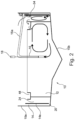
- a fan 19 (shown in figure 3 ) will be installed which generates a negative pressure and which pulls the air bubbles out from the water. Because of the negative pressure and a large surface between the air bubbles and water this method will efficiently remove CO 2 from the water.
- Figure 2 shows embodiments where several ring chambers are arranged so that different water treatment methods can be carried out in the different ring chambers.
- the first ring chamber 14 is split into several part chambers so that the water circulates from one part chamber and over into the next part chamber.
- ring chamber 14 can be divided by vertical walls so that the water circulates circularly from one part chamber and over into the next part chamber.
- the part chambers are below each other, separated by horizontal wall sections.
- FIG 2 a presently preferred embodiment of the invention is shown.
- a tank 10 is fitted with several ring chambers 14,24.
- a second ring chamber 24 Arranged inside the first ring chamber 14 is a second ring chamber 24 and water is led from the first ring chamber 14 via this second ring chamber 24 to the main chamber 12, preferably via overflow.
- a first ring chamber 12 is used for aeration and skimming (as explained above) and the second ring chamber 24 is used for biofiltration.
- a drainage well 34 is also shown bordering on to the upper section of the first ring chamber 14, for transfer of foam (skimming) i.e. removal of foam and polluting particles from the water.
- Figure 2 also shows a third ring chamber 44 which is used for oxygenating the water.
- CO 2 that is produced by the biofilter in the second ring chamber 14 is also removed here before the water enters the main chamber 12.
- the third ring chamber is, in the embodiment in figure 2 , placed such that water flows from the second ring chamber 24 via overflow to the third ring chamber 44.
- Openings 44a are arranged in a third ring chamber 44, preferably in the bottom section of the ring chamber 44 such that water flows from the third ring chamber to the main chamber 12. Oxygen and/or air is supplied to the water in the third ring chamber 44 at the same time as CO 2 is removed with the help of additions of small air bubbles in the water.
- the flow of water is indicated with arrows in the figures, i.e. water is led from the main chamber 12 via the pipeline 16 to the first ring chamber 14, and then vertically down and through the openings 20 in the bottom section of the second ring chamber 24. Air is supplied in the second ring chamber 24 to establish a vertical circular movement of the water in the ring chamber 24 before it flows on via overflow to the third ring chamber 44 and thereafter via openings in the bottom section in the third ring chamber 44 to the main chamber 12. In this circular flow movement, water passes through different water treatment processes arranged in different ring chambers 14,24,44 externally to the main chamber 12.
- the different ring chambers 14,24,44 can have any possible shape and size. However, to obtain a compact installation 10 it is preferred that one or more of the ring chambers have a vertical extension corresponding to the vertical extension of the tank 10.
- FIG 3 shows schematically in section a detail of the main chamber 12, the first ring chamber 14, second ring chamber 24 and a third ring chamber 44 and also the different water levels that are established.
- the water level in the main chamber 12 is given as V1 and is the lowest water level.
- the water level in the first ring chamber 14, given as V2 is the highest water level.
- the other ring chambers have successively lower water levels so that the second ring chamber 24 has a water level V3 which is lower than V2, but higher than the water level V4 for the third ring chamber 44. Therefore, the water is forced to flow from the first ring chamber 14, via the second ring chamber 24 via the third ring chamber 44 and to the main chamber 12.
- the tank 10 is fitted with a roof. Furthermore, the outer walls of the tank are preferably insulated, and the roof is also insulated. The walls between the different ring chambers, and the wall between the main chamber and the ring chamber is preferably made from thin plastic plates or tarpaulin, and structurally fastened to the roof at several points.
- tank/vessel is for placing on land, it is preferably manufactured from steel, concrete or plastic and covered internally by plastic.
- Figure 4 shows an embodiment which does not form part of the invention where water is led centrally in the main chamber 12 to a position at the outer edge of the main chamber 12. It is preferred that the water is led to a position adjoining the outside of the ring chamber 14.
Landscapes
- Life Sciences & Earth Sciences (AREA)
- Environmental Sciences (AREA)
- Marine Sciences & Fisheries (AREA)
- Biodiversity & Conservation Biology (AREA)
- Animal Husbandry (AREA)
- Zoology (AREA)
- Chemical & Material Sciences (AREA)
- Chemical Kinetics & Catalysis (AREA)
- Hydrology & Water Resources (AREA)
- Water Supply & Treatment (AREA)
- Environmental & Geological Engineering (AREA)
- Engineering & Computer Science (AREA)
- Organic Chemistry (AREA)
- Farming Of Fish And Shellfish (AREA)
- Housing For Livestock And Birds (AREA)
- Electrical Discharge Machining, Electrochemical Machining, And Combined Machining (AREA)
- Gas Separation By Absorption (AREA)
- Treating Waste Gases (AREA)
- Artificial Fish Reefs (AREA)
Claims (15)
- Réservoir (10) destiné à l'élevage d'organismes marins, le réservoir (10) comprenant
une chambre principale (12) destinée à contenir les organismes marins, ledit réservoir comprenant également une première chambre annulaire (14) agencée à la périphérie de la chambre principale (12) et l'eau de la chambre principale (12) circulant par l'intermédiaire de canalisations (16) vers la première chambre annulaire, caractérisé en ce que les canalisations (16) sont disposées à proximité du centre de la chambre principale (12) et sont équipées d'un dispositif de pompage (18) qui élève l'eau suffisamment haut de façon à ce que l'eau s'écoule librement dans une section inclinée horizontalement (16a) des canalisations (16) jusqu'à la première chambre annulaire (14), et en ce qu'une pompe à vide (19), telle qu'un ventilateur (19), est disposée en communication avec les canalisations (16) et installée de manière à ce qu'une pression négative soit établie dans la section inclinée horizontalement (16a) des canalisations. - Réservoir (10) selon la revendication 1, caractérisé en ce que l'eau circule par l'intermédiaire desdites canalisations (16) jusqu'à la première chambre annulaire (14) et des ouvertures (20) se trouvant dans une paroi (14a) de la première chambre annulaire (14) installées de manière à ce que l'eau soit renvoyée vers la chambre principale (12).
- Réservoir (10) selon la revendication 1, caractérisé en ce que le réservoir (10) comprend une seconde chambre annulaire (24) le long de la périphérie de la chambre principale (12) et extérieurement par rapport à celle-ci et intérieurement pour la première chambre annulaire (14), ladite eau circulant depuis la chambre principale (12) par l'intermédiaire de la première chambre annulaire (14) et ensuite par l'intermédiaire de la seconde chambre annulaire (24) et étant renvoyée vers la chambre principale (12).
- Réservoir (10) selon l'une des revendications précédentes, caractérisé en ce que le dispositif de pompage (18) est une pompe à hélice (18).
- Réservoir (10) selon la revendication 1, ladite pression négative et ladite mise à l'atmosphère des canalisations (16) étant établies avec un cyclone.
- Réservoir (10) selon la revendication 4 ou 5, caractérisé en ce que l'eau circule lentement par l'intermédiaire des canalisations (16) de sorte que l'eau soit soumise à une pression négative pendant une longue période.
- Réservoir (10) selon la revendication 1, ledit dispositif de pompage comprenant un injecteur (17) permettant l'adjonction de petites bulles de gaz, de préférence des microbulles, et plus préférablement des microbulles d'air, dans le liquide qui est acheminé à travers lesdites canalisations (16), ou des moyens d'alimentation en air (30) étant disposés dans la première chambre annulaire (14) pour l'alimentation en air, de préférence de l'air dirigé vers le haut dans la première chambre annulaire (14), ou des microbulles étant ajoutées par l'intermédiaire d'un injecteur dans la première chambre annulaire (14), ou ledit réservoir (10) comprenant également un ou plusieurs puits de drainage (34) disposés périphériquement à proximité de la section supérieure de la première chambre annulaire (14) de sorte que la mousse soit transférée de la première chambre annulaire (14) aux puits de drainage (34).
- Réservoir (10) selon la revendication 3, caractérisé en ce que ladite seconde chambre annulaire (24) est installée sous la forme d'un biofiltre, de préférence en ce que de l'air est insufflé dans la chambre (24) et met l'eau dans un mouvement de circulation et que dans l'eau, un grand nombre de corps de grande surface sont agencés pour la nitrification de l'eau.
- Réservoir (10) selon l'une quelconque des revendications 1 à 8, caractérisé en ce que le réservoir (10) comprend une autre chambre annulaire (44) périphérique par rapport à la chambre principale (12) dans sa section supérieure, cette autre chambre (44) comprenant des moyens destinés à alimenter en oxygène et/ou en air l'eau dans ladite autre chambre annulaire (44).
- Réservoir (10) selon la revendication 9, caractérisé en ce que l'eau provenant de l'autre chambre annulaire (44) circule vers la chambre principale (12) par l'intermédiaire d'un trop-plein disposé dans l'autre chambre annulaire (44).
- Réservoir (10) selon l'une quelconque des revendications 1 à 10 et au moins les revendications 3 et 9, caractérisé en ce que le réservoir (10) comprend ladite chambre principale (12) avec un niveau d'eau V1, ladite première chambre annulaire (14) avec un niveau d'eau V2, ladite seconde chambre annulaire (24) avec un niveau d'eau V3 et ladite autre chambre annulaire (44) avec un niveau d'eau V4 établis de sorte que le niveau d'eau V1 soit le niveau d'eau le plus bas et où le niveau d'eau V2 dans la première chambre annulaire (14) soit le niveau d'eau le plus élevé et où les niveaux d'eau respectifs V3 et V4 sont successivement inférieurs à V2, mais supérieurs à V1.
- Réservoir (10) selon l'une quelconque des revendications 1 à 11, ladite première chambre annulaire (14) comprenant plusieurs buses le long de la circonférence de la chambre (14) installées pour alimenter en air à la chambre de sorte que l'eau circule et soit aérée dans la chambre (14), ou ladite première chambre annulaire (14) comportant une extension verticale correspondant à la profondeur verticale de la section de paroi (10a) du réservoir (10), ou ladite seconde chambre annulaire (24) selon la revendication 3 comportant une extension verticale correspondant à la profondeur verticale d'une section de paroi (10a) du réservoir (10).
- Réservoir (10) selon l'une quelconque des revendications 1 à 12 et au moins la revendication 3, lesdits moyens étant disposés dans la seconde chambre annulaire (24) de manière à insuffler de l'air vers le haut le long d'une paroi dans la seconde chambre annulaire (24) de sorte que l'eau soit mise en rotation verticalement dans la seconde chambre annulaire (24).
- Réservoir (10) selon l'une quelconque des revendications 1 à 13, le fond de la chambre principale (12) descendant vers le centre du puits dans lequel se trouve une collection d'organismes marins morts et de déchets, ou une paroi externe dans la chambre principale (12) étant isolée, ou un toit étant placé sur le réservoir (10) et ledit toit étant dimensionné de manière à soulever et à ancrer les parois entre lesdites une ou plusieurs chambres annulaires et entre lesdites une ou plusieurs chambres annulaires et la chambre principale, ou
ladite première chambre annulaire (14) étant divisée en une multitude de chambres partielles, par des sections de paroi soit horizontales, soit verticales. - Réservoir (10) selon la revendication 14, différents procédés de traitement de l'eau étant effectués dans les différentes chambres partielles.
Applications Claiming Priority (2)
| Application Number | Priority Date | Filing Date | Title |
|---|---|---|---|
| NO20180333A NO344276B1 (no) | 2018-03-06 | 2018-03-06 | Oppdrettsmerd |
| PCT/NO2019/050050 WO2019172776A1 (fr) | 2018-03-06 | 2019-03-06 | Cage d'aquaculture comprenant une chambre principale et une chambre annulaire périphérique |
Publications (4)
| Publication Number | Publication Date |
|---|---|
| EP3761782A1 EP3761782A1 (fr) | 2021-01-13 |
| EP3761782A4 EP3761782A4 (fr) | 2021-12-15 |
| EP3761782C0 EP3761782C0 (fr) | 2024-12-04 |
| EP3761782B1 true EP3761782B1 (fr) | 2024-12-04 |
Family
ID=67846228
Family Applications (1)
| Application Number | Title | Priority Date | Filing Date |
|---|---|---|---|
| EP19764456.0A Active EP3761782B1 (fr) | 2018-03-06 | 2019-03-06 | Réservoir d'aquaculture comprenant une chambre principale et une chambre annulaire périphérique |
Country Status (6)
| Country | Link |
|---|---|
| US (1) | US11684046B2 (fr) |
| EP (1) | EP3761782B1 (fr) |
| JP (1) | JP7270656B2 (fr) |
| CN (1) | CN112118733B (fr) |
| NO (4) | NO344276B1 (fr) |
| WO (1) | WO2019172776A1 (fr) |
Families Citing this family (7)
| Publication number | Priority date | Publication date | Assignee | Title |
|---|---|---|---|---|
| NO347070B1 (no) * | 2019-04-29 | 2023-05-02 | Searas As | Anordning for multippel skimming |
| US20220061275A1 (en) * | 2020-09-02 | 2022-03-03 | Jiangsu Academy Of Agricultural Sciences | Ecological culture method for fish that contains marine barracuda |
| NO347408B1 (en) * | 2020-09-30 | 2023-10-23 | Csub As | Fiber-reinforced plastic material aquaculture tank |
| CA3218389A1 (fr) * | 2021-05-14 | 2022-11-17 | Alf Reidar Sandstad | Cage d'elevage de poissons utilisant une biomasse vivante comme force d'entrainement pour l'echange d'eau |
| SE2150766A1 (en) * | 2021-06-14 | 2022-10-18 | Amfitop Solid Surface Products | An aquafarming tank for growing marine species and a method of constructing the aquafarming tank |
| NO348642B1 (no) * | 2023-02-06 | 2025-04-14 | Searas As | Løsning for vannbehandling i kar |
| NO348615B1 (en) | 2023-11-10 | 2025-03-31 | Mmc First Process As | A live fish tank re-circulation arrangement |
Family Cites Families (33)
| Publication number | Priority date | Publication date | Assignee | Title |
|---|---|---|---|---|
| GB1110020A (en) | 1965-07-22 | 1968-04-18 | Raymond George Girard | Method and apparatus for preventing cannibalism in the rearing of tropical fish |
| JPS5437760Y2 (fr) * | 1974-11-09 | 1979-11-12 | ||
| US3996893A (en) * | 1974-12-20 | 1976-12-14 | Buss Keen W | Fish husbandry system |
| US4211183A (en) * | 1977-08-08 | 1980-07-08 | Hoult David P | Fish raising |
| DE2829496A1 (de) * | 1978-07-05 | 1980-01-31 | Recentec Umwelttech Gmbh | Vorrichtung zur haltung und aufzucht von im wasser lebenden lebewesen |
| FR2573875B1 (fr) | 1984-11-23 | 1987-01-16 | Marseille Eaux | Procedes et dispositifs pour detecter la pollution de l'eau |
| JPS6471428A (en) * | 1987-09-10 | 1989-03-16 | Seinan Jidosha Kogyo Kk | Filter device for live fish tank |
| NO884198L (no) | 1988-09-22 | 1990-03-23 | Sinvent As | Luftdiffusor for stroemsetting av vann i basseng/kar. |
| JP3022030U (ja) * | 1995-08-25 | 1996-03-12 | 守哉 南浦 | 水産物の養殖設備 |
| JP2002058387A (ja) * | 2000-08-21 | 2002-02-26 | Igarashi Hiroshi | 水棲生物飼育装置 |
| JP2002360110A (ja) * | 2001-06-05 | 2002-12-17 | Mitsui Norin Marine Products Development Co Ltd | 砂地生息水中生物の養殖装置 |
| NO20014797L (no) * | 2001-10-03 | 2003-04-04 | Eco Farm As | Fremgangsmåte og anordning for behandling av vann i landbasert oppdrettsanlegg |
| JP2003259759A (ja) * | 2002-03-07 | 2003-09-16 | Japan Aqua Tec Co Ltd | 魚類飼育水槽の二酸化炭素除去装置 |
| JP2003265065A (ja) * | 2002-03-15 | 2003-09-24 | Igaki:Kk | 養殖用水槽 |
| JP2005131455A (ja) * | 2003-10-28 | 2005-05-26 | Mitsubishi Heavy Ind Ltd | 中空の浄化媒体および浄化装置 |
| JP3930880B2 (ja) * | 2003-11-25 | 2007-06-13 | 株式会社陸上養殖工学研究所 | 循環濾過式養殖装置 |
| JP2006272307A (ja) * | 2005-03-28 | 2006-10-12 | Nanoplanet Kenkyusho:Kk | マイクロバブルによる自然水域又は自然水を入れた水槽水の浄化方法及び浄化システム |
| US7771515B2 (en) * | 2006-07-13 | 2010-08-10 | Institut National Des Sciences Appliquees | Method and installation for treating an aqueous effluent, in order to extract at least one dissolved gaseous compound; application to aquaculture in recirculated aqueous medium |
| US8506811B2 (en) * | 2007-03-01 | 2013-08-13 | Bradley Innovation Group, Llc | Process and system for growing crustaceans and other fish |
| US20100206240A1 (en) | 2007-11-09 | 2010-08-19 | Keepalive, Inc. | Endless stream fish tank |
| US9268746B2 (en) * | 2008-03-07 | 2016-02-23 | St Ericsson Sa | Architecture for vector memory array transposition using a block transposition accelerator |
| NO330681B1 (no) * | 2010-04-30 | 2011-06-06 | Hobas As | Oppdrettssystem for akvatiske organismer |
| KR101330704B1 (ko) * | 2011-10-24 | 2013-11-19 | 유병화 | 에어리프트를 이용한 순환식 양식 시스템 |
| KR101315624B1 (ko) * | 2013-01-10 | 2013-10-08 | 유병화 | 순환 여과식 양식시스템 |
| CN103071318B (zh) * | 2013-01-30 | 2015-04-15 | 华东理工大学 | 利用旋流或离心场与压力梯度场耦合进行液体脱气的装置 |
| CN103130382B (zh) * | 2013-03-15 | 2014-06-11 | 重庆大学 | 一种曝气生物滤池与人工湿地组合污水低碳处理反应器 |
| DK2996465T4 (da) * | 2013-05-14 | 2024-02-19 | Veolia Water Solutions & Tech Support Sas | Fiskeopdrætsanlæg og anvendelse deraf |
| CN205337242U (zh) * | 2015-12-25 | 2016-06-29 | 广东何氏水产有限公司 | 活鱼养殖池 |
| MY195142A (en) * | 2016-04-07 | 2023-01-11 | Nordahl Pedersen Geir | Installation and Method for Farming of Fish |
| CN106259137B (zh) * | 2016-08-09 | 2019-11-08 | 中国水产科学研究院南海水产研究所 | 一种跑道式高密度封闭水产养殖系统及养殖水产的方法 |
| NO342403B1 (no) * | 2016-09-07 | 2018-05-14 | Searas As | Lukket merd |
| WO2018151605A1 (fr) * | 2017-02-14 | 2018-08-23 | Rognsoey Richard | Agencement de récipient pour pisciculture |
| IL252390A (en) * | 2017-05-18 | 2018-04-30 | Latimeria Ltd | A method and system for maintaining water quality |
-
2018
- 2018-03-06 NO NO20180333A patent/NO344276B1/no unknown
-
2019
- 2019-02-22 NO NO20190247A patent/NO20190247A1/no not_active Application Discontinuation
- 2019-03-06 JP JP2020570386A patent/JP7270656B2/ja active Active
- 2019-03-06 CN CN201980017156.1A patent/CN112118733B/zh active Active
- 2019-03-06 WO PCT/NO2019/050050 patent/WO2019172776A1/fr not_active Ceased
- 2019-03-06 US US16/978,704 patent/US11684046B2/en active Active
- 2019-03-06 EP EP19764456.0A patent/EP3761782B1/fr active Active
-
2020
- 2020-10-02 NO NO20201078A patent/NO20201078A1/en unknown
- 2020-10-05 NO NO20201080A patent/NO20201080A1/en unknown
Also Published As
| Publication number | Publication date |
|---|---|
| NO20201080A1 (en) | 2020-10-05 |
| CA3091737A1 (fr) | 2019-09-12 |
| WO2019172776A1 (fr) | 2019-09-12 |
| NO20190247A1 (no) | 2019-09-09 |
| NO344276B1 (no) | 2019-10-28 |
| CN112118733B (zh) | 2022-10-11 |
| JP7270656B2 (ja) | 2023-05-10 |
| US11684046B2 (en) | 2023-06-27 |
| CN112118733A (zh) | 2020-12-22 |
| EP3761782A1 (fr) | 2021-01-13 |
| JP2021516067A (ja) | 2021-07-01 |
| EP3761782C0 (fr) | 2024-12-04 |
| NO20201078A1 (en) | 2020-10-02 |
| EP3761782A4 (fr) | 2021-12-15 |
| US20210092941A1 (en) | 2021-04-01 |
| NO20180333A1 (no) | 2019-09-09 |
Similar Documents
| Publication | Publication Date | Title |
|---|---|---|
| EP3761782B1 (fr) | Réservoir d'aquaculture comprenant une chambre principale et une chambre annulaire périphérique | |
| US3235234A (en) | Apparatus for aerating water | |
| FI130256B (en) | Water circulation and aeration system for an aquaculture facility, related facility, procedures and use | |
| CN108773970B (zh) | 漂浮式综合水处理设备、水处理方法及该设备的反洗方法 | |
| CS210625B2 (en) | Method of sewage biological treatment by aeration and equipment for making the same | |
| US5421999A (en) | Floating nitrification reactor in a treatment pond | |
| CN102317215A (zh) | 用于从水性介质中去除不想要的物质的水下系统及方法 | |
| US20080185344A1 (en) | Aeration Method, Aeration Apparatus and Aeration System | |
| KR100512089B1 (ko) | 고속 고효율 폭기장치 | |
| WO2016159870A1 (fr) | Bioréacteur à lit mobile et procédé de traitement de l'eau | |
| US10654732B2 (en) | Equipment and process for massive dissolution of gases in liquids | |
| CN204211537U (zh) | 一体化兼氧mbr膜生物反应器 | |
| KR20220075694A (ko) | 에너지 절감이 가능한 순환여과시스템의 수처리 시스템 | |
| CA3091737C (fr) | Cage d'aquaculture comprenant une chambre principale et une chambre annulaire peripherique | |
| KR100762885B1 (ko) | 다단 혼합 구조를 갖는 슬림형 고속 폭기장치 | |
| KR950007910B1 (ko) | 다중기상 침전조 | |
| CN205258117U (zh) | 漂浮式曝气溶氧生物循环水处理装置及水处理系统 | |
| RU2754363C2 (ru) | Способ циркуляции воды в замкнутой системе водоснабжения для содержания гидробионтов | |
| KR101149063B1 (ko) | 부유형 호소 정화장치 | |
| LV15092B (lv) | Zivju audzēšanas komplekss un ūdens reģenerēšanas paņēmiens tajā | |
| KR101767402B1 (ko) | 수체 내 산소 공급 장치 | |
| JP3158262B2 (ja) | 養殖海域における海流生成方法及び施設 | |
| JPS638472Y2 (fr) | ||
| JP2001047088A (ja) | 水改質装置 | |
| WO2018151587A1 (fr) | Mécanisme autonome flottant pour aérer des corps d'eau |
Legal Events
| Date | Code | Title | Description |
|---|---|---|---|
| STAA | Information on the status of an ep patent application or granted ep patent |
Free format text: STATUS: THE INTERNATIONAL PUBLICATION HAS BEEN MADE |
|
| PUAI | Public reference made under article 153(3) epc to a published international application that has entered the european phase |
Free format text: ORIGINAL CODE: 0009012 |
|
| STAA | Information on the status of an ep patent application or granted ep patent |
Free format text: STATUS: REQUEST FOR EXAMINATION WAS MADE |
|
| 17P | Request for examination filed |
Effective date: 20201006 |
|
| AK | Designated contracting states |
Kind code of ref document: A1 Designated state(s): AL AT BE BG CH CY CZ DE DK EE ES FI FR GB GR HR HU IE IS IT LI LT LU LV MC MK MT NL NO PL PT RO RS SE SI SK SM TR |
|
| AX | Request for extension of the european patent |
Extension state: BA ME |
|
| DAV | Request for validation of the european patent (deleted) | ||
| DAX | Request for extension of the european patent (deleted) | ||
| A4 | Supplementary search report drawn up and despatched |
Effective date: 20211116 |
|
| RIC1 | Information provided on ipc code assigned before grant |
Ipc: A01K 63/04 20060101ALI20211110BHEP Ipc: A01K 63/00 20170101ALI20211110BHEP Ipc: A01K 61/60 20170101AFI20211110BHEP |
|
| GRAP | Despatch of communication of intention to grant a patent |
Free format text: ORIGINAL CODE: EPIDOSNIGR1 |
|
| STAA | Information on the status of an ep patent application or granted ep patent |
Free format text: STATUS: GRANT OF PATENT IS INTENDED |
|
| RIC1 | Information provided on ipc code assigned before grant |
Ipc: C02F 9/00 20060101ALI20240229BHEP Ipc: B01D 19/00 20060101ALI20240229BHEP Ipc: A01K 63/04 20060101ALI20240229BHEP Ipc: A01K 63/00 20170101ALI20240229BHEP Ipc: A01K 61/60 20170101AFI20240229BHEP |
|
| INTG | Intention to grant announced |
Effective date: 20240320 |
|
| GRAS | Grant fee paid |
Free format text: ORIGINAL CODE: EPIDOSNIGR3 |
|
| GRAA | (expected) grant |
Free format text: ORIGINAL CODE: 0009210 |
|
| STAA | Information on the status of an ep patent application or granted ep patent |
Free format text: STATUS: THE PATENT HAS BEEN GRANTED |
|
| AK | Designated contracting states |
Kind code of ref document: B1 Designated state(s): AL AT BE BG CH CY CZ DE DK EE ES FI FR GB GR HR HU IE IS IT LI LT LU LV MC MK MT NL NO PL PT RO RS SE SI SK SM TR |
|
| REG | Reference to a national code |
Ref country code: CH Ref legal event code: EP |
|
| REG | Reference to a national code |
Ref country code: DE Ref legal event code: R096 Ref document number: 602019062990 Country of ref document: DE |
|
| REG | Reference to a national code |
Ref country code: IE Ref legal event code: FG4D |
|
| U01 | Request for unitary effect filed |
Effective date: 20241219 |
|
| U07 | Unitary effect registered |
Designated state(s): AT BE BG DE DK EE FI FR IT LT LU LV MT NL PT RO SE SI Effective date: 20250210 |
|
| U20 | Renewal fee for the european patent with unitary effect paid |
Year of fee payment: 7 Effective date: 20250215 |
|
| PG25 | Lapsed in a contracting state [announced via postgrant information from national office to epo] |
Ref country code: HR Free format text: LAPSE BECAUSE OF FAILURE TO SUBMIT A TRANSLATION OF THE DESCRIPTION OR TO PAY THE FEE WITHIN THE PRESCRIBED TIME-LIMIT Effective date: 20241204 |
|
| PG25 | Lapsed in a contracting state [announced via postgrant information from national office to epo] |
Ref country code: ES Free format text: LAPSE BECAUSE OF FAILURE TO SUBMIT A TRANSLATION OF THE DESCRIPTION OR TO PAY THE FEE WITHIN THE PRESCRIBED TIME-LIMIT Effective date: 20241204 |
|
| PG25 | Lapsed in a contracting state [announced via postgrant information from national office to epo] |
Ref country code: NO Free format text: LAPSE BECAUSE OF FAILURE TO SUBMIT A TRANSLATION OF THE DESCRIPTION OR TO PAY THE FEE WITHIN THE PRESCRIBED TIME-LIMIT Effective date: 20250304 |
|
| PG25 | Lapsed in a contracting state [announced via postgrant information from national office to epo] |
Ref country code: GR Free format text: LAPSE BECAUSE OF FAILURE TO SUBMIT A TRANSLATION OF THE DESCRIPTION OR TO PAY THE FEE WITHIN THE PRESCRIBED TIME-LIMIT Effective date: 20250305 |
|
| PG25 | Lapsed in a contracting state [announced via postgrant information from national office to epo] |
Ref country code: RS Free format text: LAPSE BECAUSE OF FAILURE TO SUBMIT A TRANSLATION OF THE DESCRIPTION OR TO PAY THE FEE WITHIN THE PRESCRIBED TIME-LIMIT Effective date: 20250304 |
|
| PG25 | Lapsed in a contracting state [announced via postgrant information from national office to epo] |
Ref country code: SM Free format text: LAPSE BECAUSE OF FAILURE TO SUBMIT A TRANSLATION OF THE DESCRIPTION OR TO PAY THE FEE WITHIN THE PRESCRIBED TIME-LIMIT Effective date: 20241204 |
|
| PG25 | Lapsed in a contracting state [announced via postgrant information from national office to epo] |
Ref country code: PL Free format text: LAPSE BECAUSE OF FAILURE TO SUBMIT A TRANSLATION OF THE DESCRIPTION OR TO PAY THE FEE WITHIN THE PRESCRIBED TIME-LIMIT Effective date: 20241204 |
|
| PG25 | Lapsed in a contracting state [announced via postgrant information from national office to epo] |
Ref country code: SK Free format text: LAPSE BECAUSE OF FAILURE TO SUBMIT A TRANSLATION OF THE DESCRIPTION OR TO PAY THE FEE WITHIN THE PRESCRIBED TIME-LIMIT Effective date: 20241204 |
|
| PG25 | Lapsed in a contracting state [announced via postgrant information from national office to epo] |
Ref country code: CZ Free format text: LAPSE BECAUSE OF FAILURE TO SUBMIT A TRANSLATION OF THE DESCRIPTION OR TO PAY THE FEE WITHIN THE PRESCRIBED TIME-LIMIT Effective date: 20241204 |
|
| PLBE | No opposition filed within time limit |
Free format text: ORIGINAL CODE: 0009261 |
|
| STAA | Information on the status of an ep patent application or granted ep patent |
Free format text: STATUS: NO OPPOSITION FILED WITHIN TIME LIMIT |
|
| PG25 | Lapsed in a contracting state [announced via postgrant information from national office to epo] |
Ref country code: MC Free format text: LAPSE BECAUSE OF FAILURE TO SUBMIT A TRANSLATION OF THE DESCRIPTION OR TO PAY THE FEE WITHIN THE PRESCRIBED TIME-LIMIT Effective date: 20241204 |
|
| REG | Reference to a national code |
Ref country code: CH Ref legal event code: L10 Free format text: ST27 STATUS EVENT CODE: U-0-0-L10-L00 (AS PROVIDED BY THE NATIONAL OFFICE) Effective date: 20251015 |
|
| REG | Reference to a national code |
Ref country code: CH Ref legal event code: H13 Free format text: ST27 STATUS EVENT CODE: U-0-0-H10-H13 (AS PROVIDED BY THE NATIONAL OFFICE) Effective date: 20251023 |
|
| 26N | No opposition filed |
Effective date: 20250905 |
|
| PG25 | Lapsed in a contracting state [announced via postgrant information from national office to epo] |
Ref country code: CH Free format text: LAPSE BECAUSE OF NON-PAYMENT OF DUE FEES Effective date: 20250331 |
|
| PG25 | Lapsed in a contracting state [announced via postgrant information from national office to epo] |
Ref country code: IE Free format text: LAPSE BECAUSE OF NON-PAYMENT OF DUE FEES Effective date: 20250306 |
|
| U20 | Renewal fee for the european patent with unitary effect paid |
Year of fee payment: 8 Effective date: 20260217 |
|
| PGFP | Annual fee paid to national office [announced via postgrant information from national office to epo] |
Ref country code: GB Payment date: 20260323 Year of fee payment: 8 |
|
| PGFP | Annual fee paid to national office [announced via postgrant information from national office to epo] |
Ref country code: IS Payment date: 20260224 Year of fee payment: 8 |