EP3765794B1 - A universal radiator - Google Patents
A universal radiator Download PDFInfo
- Publication number
- EP3765794B1 EP3765794B1 EP19720355.7A EP19720355A EP3765794B1 EP 3765794 B1 EP3765794 B1 EP 3765794B1 EP 19720355 A EP19720355 A EP 19720355A EP 3765794 B1 EP3765794 B1 EP 3765794B1
- Authority
- EP
- European Patent Office
- Prior art keywords
- bushing
- lower bushing
- heating medium
- pipe
- radiator
- Prior art date
- Legal status (The legal status is an assumption and is not a legal conclusion. Google has not performed a legal analysis and makes no representation as to the accuracy of the status listed.)
- Active
Links
Images


Classifications
-
- F—MECHANICAL ENGINEERING; LIGHTING; HEATING; WEAPONS; BLASTING
- F24—HEATING; RANGES; VENTILATING
- F24D—DOMESTIC- OR SPACE-HEATING SYSTEMS, e.g. CENTRAL HEATING SYSTEMS; DOMESTIC HOT-WATER SUPPLY SYSTEMS; ELEMENTS OR COMPONENTS THEREFOR
- F24D19/00—Details
- F24D19/0002—Means for connecting central heating radiators to circulation pipes
- F24D19/0078—Plugs
-
- F—MECHANICAL ENGINEERING; LIGHTING; HEATING; WEAPONS; BLASTING
- F24—HEATING; RANGES; VENTILATING
- F24D—DOMESTIC- OR SPACE-HEATING SYSTEMS, e.g. CENTRAL HEATING SYSTEMS; DOMESTIC HOT-WATER SUPPLY SYSTEMS; ELEMENTS OR COMPONENTS THEREFOR
- F24D19/00—Details
- F24D19/0002—Means for connecting central heating radiators to circulation pipes
-
- F—MECHANICAL ENGINEERING; LIGHTING; HEATING; WEAPONS; BLASTING
- F28—HEAT EXCHANGE IN GENERAL
- F28D—HEAT-EXCHANGE APPARATUS, NOT PROVIDED FOR IN ANOTHER SUBCLASS, IN WHICH THE HEAT-EXCHANGE MEDIA DO NOT COME INTO DIRECT CONTACT
- F28D1/00—Heat-exchange apparatus having stationary conduit assemblies for one heat-exchange medium only, the media being in contact with different sides of the conduit wall, in which the other heat-exchange medium is a large body of fluid, e.g. domestic or motor car radiators
- F28D1/02—Heat-exchange apparatus having stationary conduit assemblies for one heat-exchange medium only, the media being in contact with different sides of the conduit wall, in which the other heat-exchange medium is a large body of fluid, e.g. domestic or motor car radiators with heat-exchange conduits immersed in the body of fluid
- F28D1/04—Heat-exchange apparatus having stationary conduit assemblies for one heat-exchange medium only, the media being in contact with different sides of the conduit wall, in which the other heat-exchange medium is a large body of fluid, e.g. domestic or motor car radiators with heat-exchange conduits immersed in the body of fluid with tubular conduits
- F28D1/053—Heat-exchange apparatus having stationary conduit assemblies for one heat-exchange medium only, the media being in contact with different sides of the conduit wall, in which the other heat-exchange medium is a large body of fluid, e.g. domestic or motor car radiators with heat-exchange conduits immersed in the body of fluid with tubular conduits the conduits being straight
- F28D1/0535—Heat-exchange apparatus having stationary conduit assemblies for one heat-exchange medium only, the media being in contact with different sides of the conduit wall, in which the other heat-exchange medium is a large body of fluid, e.g. domestic or motor car radiators with heat-exchange conduits immersed in the body of fluid with tubular conduits the conduits being straight the conduits having a non-circular cross-section
- F28D1/05366—Assemblies of conduits connected to common headers, e.g. core type radiators
- F28D1/05375—Assemblies of conduits connected to common headers, e.g. core type radiators with particular pattern of flow, e.g. change of flow direction
-
- F—MECHANICAL ENGINEERING; LIGHTING; HEATING; WEAPONS; BLASTING
- F28—HEAT EXCHANGE IN GENERAL
- F28F—DETAILS OF HEAT-EXCHANGE AND HEAT-TRANSFER APPARATUS, OF GENERAL APPLICATION
- F28F9/00—Casings; Header boxes; Auxiliary supports for elements; Auxiliary members within casings
- F28F9/02—Header boxes; End plates
- F28F9/026—Header boxes; End plates with static flow control means, e.g. with means for uniformly distributing heat exchange media into conduits
- F28F9/027—Header boxes; End plates with static flow control means, e.g. with means for uniformly distributing heat exchange media into conduits in the form of distribution pipes
-
- F—MECHANICAL ENGINEERING; LIGHTING; HEATING; WEAPONS; BLASTING
- F28—HEAT EXCHANGE IN GENERAL
- F28F—DETAILS OF HEAT-EXCHANGE AND HEAT-TRANSFER APPARATUS, OF GENERAL APPLICATION
- F28F9/00—Casings; Header boxes; Auxiliary supports for elements; Auxiliary members within casings
- F28F9/26—Arrangements for connecting different sections of heat-exchange elements, e.g. of radiators
- F28F9/262—Arrangements for connecting different sections of heat-exchange elements, e.g. of radiators for radiators
-
- F—MECHANICAL ENGINEERING; LIGHTING; HEATING; WEAPONS; BLASTING
- F24—HEATING; RANGES; VENTILATING
- F24D—DOMESTIC- OR SPACE-HEATING SYSTEMS, e.g. CENTRAL HEATING SYSTEMS; DOMESTIC HOT-WATER SUPPLY SYSTEMS; ELEMENTS OR COMPONENTS THEREFOR
- F24D2220/00—Components of central heating installations excluding heat sources
- F24D2220/20—Heat consumers
- F24D2220/2009—Radiators
- F24D2220/2018—Column radiators having vertically extending tubes
-
- F—MECHANICAL ENGINEERING; LIGHTING; HEATING; WEAPONS; BLASTING
- F24—HEATING; RANGES; VENTILATING
- F24D—DOMESTIC- OR SPACE-HEATING SYSTEMS, e.g. CENTRAL HEATING SYSTEMS; DOMESTIC HOT-WATER SUPPLY SYSTEMS; ELEMENTS OR COMPONENTS THEREFOR
- F24D2220/00—Components of central heating installations excluding heat sources
- F24D2220/20—Heat consumers
- F24D2220/2009—Radiators
- F24D2220/2045—Radiators having horizontally extending tubes
-
- F—MECHANICAL ENGINEERING; LIGHTING; HEATING; WEAPONS; BLASTING
- F28—HEAT EXCHANGE IN GENERAL
- F28D—HEAT-EXCHANGE APPARATUS, NOT PROVIDED FOR IN ANOTHER SUBCLASS, IN WHICH THE HEAT-EXCHANGE MEDIA DO NOT COME INTO DIRECT CONTACT
- F28D21/00—Heat-exchange apparatus not covered by any of the groups F28D1/00 - F28D20/00
- F28D2021/0019—Other heat exchangers for particular applications; Heat exchange systems not otherwise provided for
- F28D2021/0035—Other heat exchangers for particular applications; Heat exchange systems not otherwise provided for for domestic or space heating, e.g. heating radiators
-
- F—MECHANICAL ENGINEERING; LIGHTING; HEATING; WEAPONS; BLASTING
- F28—HEAT EXCHANGE IN GENERAL
- F28F—DETAILS OF HEAT-EXCHANGE AND HEAT-TRANSFER APPARATUS, OF GENERAL APPLICATION
- F28F9/00—Casings; Header boxes; Auxiliary supports for elements; Auxiliary members within casings
- F28F9/02—Header boxes; End plates
- F28F2009/0285—Other particular headers or end plates
- F28F2009/0297—Side headers, e.g. for radiators having conduits laterally connected to common header
Definitions
- the invention relates to a universal radiator intended for heating both housing and non-housing spaces, with universal options of connecting to heating circuits.
- the background of the invention in the field can be characterized that there are several types of radiators used for heating, among which panel radiators are the most common. Furthermore, there are plenty of tube (bathroom) radiators and various design radiators that are manufactured. These radiators are often welded from tubular sections of various shapes and pipes.
- the panel radiator usually consists of two connecting bars shut with covers at the end, which are equipped with bushings used for connection to the heating circuit.
- the connecting bars can be made of steel, copper or aluminium sections or pipes and are mutually connected by heating sections.
- the heating sections can be also made of steel, copper or aluminium sections or pipes. To allow the heating medium (heating water) to flow through the radiator, the connecting bars and heating sections are linked by holes.
- the operating principle of the radiator is that the heating medium enters the radiator through one bushing and transmits the heat to the surroundings while flowing through connecting bars and heating sections. This process cools the heating medium down and the cooled medium flows through the other bushing back to the heating system.
- the bushings not used for connecting to the heating system are shut with (shut-off or deaeration) covers.
- radiators have to deal with problems about different types of connecting radiators to the heating system (e.g. from right, from left, diagonally, from below downwards) due to several reasons - structural, designing or visual ones.
- the problem with existing solutions can be characterized that when the connection is unsuitable, the radiator heat output may decrease by tens of percents.
- the input and output bushing must be installed at different connecting bars. So the heating medium flows into the radiator e.g. from the right through the upper or lower bushing, wherein it flows through the whole right connecting bar and holes to heating sections. After that the cooled heating medium flows through holes, the whole left connecting bar and the lower bushing out to the heating circuit.
- a similar connection from the left is also possible, just with the radiator connected reversely.
- a problem may arise when a one-sided lateral connection of the radiator to the heating circuit is required and when both inlet and outlet bushing are to be placed at the same side, so in one connecting bar.
- This arrangement may cause that the heating medium can flow freely (by line of least resistance) e.g. from the right upper (inlet) bushing through the connecting bar directly to the right lower (outlet) bushing without flowing through heating sections. In that case an adjustment of the radiator construction is necessary to prevent the heating medium from flowing through this shortened route.
- the typical solution of the problem described above that is used nowadays to guarantee a constant heat output of the radiator with the one-sided lateral connection is a barrier placed in one or both connection bars to guide the heating medium (heating water) stream.
- the heating medium flows into the radiator from right through the upper bushing. It flows through the upper part of the right connecting bar and through holes to upper heating sections.
- the cooled heating medium flows through upper holes to the left connecting bar and subsequently through lower holes to the lower heating sections.
- Through lower holes the heating medium flows into the lower part of the right connecting bar and subsequently it drains away from the radiator through the lower bushing, wherein the right connecting bar is divided by a barrier to the upper and lower part.
- the described necessity to have several variants of the same radiator just due to different connection types causes big problems in logistics, ordering and delivering radiators, because the customer has to define the radiator precisely according to its connection type and consequently the manufacturer has to produce and deliver the radiator of the selected type. That involves a big risk of errors during ordering and manufacturing radiators.
- the delivered radiator cannot be used e.g. when the construction layout changes and the radiator has to be connected in a different manner. So for suppliers and merchants it is impossible to have radiators in stock and ready to be picked up instantly, because they always have to take into account the construction layout etc.
- FR 2 316 568 A1 discloses a closure plate which is installed in the bottom distributing pipe of a radiator which has bottom connections at both ends. It separates the chamber connected to the ascending pipes from the chamber connected to the descending pipes.
- the plate comprises a single piece of hot water-resistant plastic material, e.g. polyphenylene oxide with 30% glass fibre content.
- the outer support has a cross-shaped profile of given length, with a sealing collar which is mounted in a threaded bore on the valve side, and a mandrel on the separating side with grooves for receiving the closure plate.
- the profile may be Y-shaped, or a bush at one end may be connected to a stop at the other end by a tube with longitudinal slots which open more than a quarter of the tube periphery.
- US 5 400 853 A discloses a modular heat exchanger system that comprises at least a primary heat exchanger having two parallel manifolds with a chosen plurality of heat exchange tubes running there between, the manifolds defining a water pathway therein within which baffles are provided to produce a serpentine path through the manifolds and heat exchange tubes of the exchanger, one of the manifolds being an intake manifold and the other being a return manifold having a terminal return chamber, the chamber feeding into a return tube extending through the manifold and exiting the opposite end thereof, the tube being of smaller diameter than the manifold and creating an annular channel there around through which liquid flowing through the exchanger is routed.
- the system further includes a secondary heat exchanger having two parallel manifolds with a chosen plurality of heat exchange tubes running there between, the manifolds defining a water pathway therein within which baffles are provided to produce a serpentine path through the manifolds and heat exchange tubes of the exchanger, one of the manifolds being an intake manifold and the other being a return manifold having a terminal return chamber, the chamber feeding into a return tube extending through the manifold and exiting the opposite end thereof, the tube being of smaller diameter than the manifold and creating an annular channel there around through which liquid flowing through the exchanger is routed, and an intake chamber at the opposite end of the manifold which is joined to the return chamber of the primary exchanger, in a manner where, upon blocking access between the return tube and return chamber of the primary exchanger, liquid from the return chamber of the primary exchanger flows into the intake chamber of the secondary exchanger.
- EP 0 972 998 A2 discloses a heating or cooling device which has a number of hollow horizontal panels, feed and return connections for a circulated heating or cooling medium and a distributor receiving the heating or cooling medium from the first horizontal panel, which is connected to the feed connection and supplying it to each of the remaining horizontal panels.
- An independent claim for a spacer for construction of a hollow horizontal panel for a heating or cooling device is also included.
- the radiator with practically universal features, as for different required connection variants, eliminates the disadvantages of current radiator embodiments. It means there is only one radiator embodiment that is manufactured in the production plant and simple assembly tools can be used to connect this radiator to the heating system as required. The need for that solution can be underlined by the fact that the radiator is equipped with welded hangers at the back side for mounting to the wall. In fact, this explicitly defines the position of the radiator towards the wall- and individual variants of connecting the radiator to the heating circuit must obey that.
- the radiator according to the invention is defined in claim 1.
- the radiator profits from the flow of the heating medium (most frequently heating water), and consists of tubular heating sections that are firmly connected (usually welded) with two peripheral tubular connecting bars. These tubular connecting bars are connected to the tubular heating sections through holes for the heating medium stream.
- Each tubular connecting bar is equipped with two bushings (with inner threads), the left tubular connecting bar with a left lower bushing (in the lower part of the left tubular connecting bar) and a left upper bushing (in the upper part of the left tubular connecting bar), the right tubular connecting bar with a right lower bushing (in the lower part of the right tubular connecting bar) and a right upper bushing (in the upper part of the right tubular connecting bar).
- the left tubular connecting bar and the right tubular connecting bar are linked by a pipe underneath. Both ends of the pipe overlap into tubular connecting bars, wherein they are coaxial with both the left lower bushing and right lower bushing and are adjusted, usually skewed for a nipple or a plug to be screwed on through the designated lower bushing.
- the nipple consists of a through tube; at one end this tube is ended with an outer flange adhered (through not visible sealing) to the inner shoulder of the right lower bushing or to the inner shoulder of the left lower bushing, wherein at its other end the through pipe of the nipple is mounted on the left end of the pipe or the right end of the pipe.
- the joint between the tube and the left end or the right end of the pipe is sealed with a not visible sealing, e.g. O-ring.
- the joint between the plug tube and the left end or the right end of the pipe is also sealed with a not visible sealing, e.g. O-ring.
- the nipple can be equipped with a thread at the periphery of its outer flange to screw into the left lower bushing or the right lower bushing.
- the nipple conducts the heating medium from the pipe via tube, through the lower bushing into the heating circuit. All four bushings have the same pipe construction with inner thread and inner shoulder.
- the front side of the outer thread for the nipple is equipped with a groove for screwing or with a hexagon socket for Allen key.
- the plug consists of a tube that is at one side ended with an outer flange adhered to the inner shoulder of the right lower bushing or to the inner shoulder of the left lower busing.
- the plug tube shut by a barrier that forms a cap
- the plug tube has at least one radial hole between the barrier and the flange used for the heating medium to flow into the relevant tubular connecting bar.
- the plug can be equipped with a thread at the periphery of its outer flange to screw into the left lower bushing or the right lower bushing.
- the front side of the outer thread of the plug is equipped with a groove for screwing.
- Fig. 4 radiator with heating medium inflow through right lower bushing and cooled heating medium outflow through left lower bushing
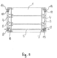
- Fig. 5 radiator with heating medium inflow through left lower bushing and cooled heating medium outflow through right lower bushing
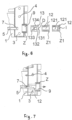
- Fig. 6 detailed representation of plug and nipples for screwing into bushing
- Fig. 7 subassembly with nipple screwed into bushing
- Fig. 8 subassembly with plug screwed into bushing.
- the radiator that takes advantage of the heating medium flow and consists of tubular heating sections 1, which are firmly connected with two peripheral tubular connecting bars 2 , 3 , while these bars are connected with tubular heating sections 1 through holes 4 , wherein each tubular connecting bar 2 , 3 is equipped with two bushings 8 , 10 and 9, 11 placed one above the other one, up and down (see Fig. 1 ); the radiator is connected to the heating medium inlet through the right upper bushing 11 and to the (cooled) heating medium outlet through the right lower bushing 9 .
- the left upper bushing 10 and left lower bushing 8 are both closed with caps 14 , wherein the right end 7 of the pipe 5 has a nipple 12 inserted through the right lower bushing 9 .
- the working principle of the described embodiment of the invention is that the hot heating medium flows into the radiator from the right through the right upper bushing 11 and flows through the entire right tubular connecting bar 3 and through holes 4 into the heating sections 1 .
- the cooled heating medium flows through holes 4 leading into the left tubular. connecting bar 2 and from there it drains away through the pipe 5 into the right lower bushing 9 .
- the radiator that takes advantage of the heating medium flow and consists of tubular heating sections 1 , which are firmly connected with two peripheral tubular connecting bars 2 , 3 , while these bars are connected with tubular heating sections 1 through holes 4 , wherein each tubular connecting bar 2 , 3 is equipped with two bushings 8 , 10 and 9 , 11 placed one above the other one, up and down (see Fig. 2 ); the radiator is connected to the heating medium inlet through the left upper bushing 10 and to the (cooled) heating medium outlet through the left lower bushing 8 .
- the right upper bushing 11 and left lower bushing 9 are both closed with caps 14 , wherein the left end 6 of the pipe 5 has a nipple 12 inserted through the left lower bushing 8 .
- the radiator that takes advantage of the heating medium flow and consists of tubular heating sections 1 , which are firmly connected with two peripheral tubular connecting bars 2 , 3 , while these bars are connected with tubular heating sections 1 through holes 4 , wherein each tubular connecting bar 2 , 3 is equipped with two bushings 8 , 10 and 9 , 11 placed one above the other one, up and down (see Fig. 3 ); the radiator is connected to the heating medium inlet through the right upper bushing 11 and to the heating medium outlet through the left lower bushing 8 .
- the left upper bushing 10 is closed with a cap 14 .
- the right end 7 of the pipe 5 has a nipple 12 inserted through the right lower bushing 9 , wherein the right lower bushing 9 is closed with a cap 14.
- the working principle of the described embodiment of the invention is that the hot heating medium flows into the radiator from the right through the right upper bushing 11 and flows through the entire right tubular connecting bar 3 and through holes 4 into the heating sections 1 ,
- the cooled heating medium flows through holes 4 leading into the left tubular connecting bar 2 and from there it drains away through the left lower bushing 8 into the heating circuit.
- the right lower bushing 9 is closed with a cap 14 , so the heating medium does not flow through the pipe 5 .
- the radiator that takes advantage of the heating medium flow and consists of tubular heating sections 1 , which are firmly connected with two peripheral tubular connecting bars 2 , 3 , while these bars are connected with tubular heating sections 1 through holes 4 , wherein each tubular connecting bar 2 , 3 is equipped with two bushings 8 , 10 and 9 , 11 placed one above the other one, up and down (see Fig. 4 ); the radiator is connected to the heating medium inlet through the right lower bushing 9 and to the heating medium outlet through the left lower bushing 8 .
- the right lower bushing 9 has a plug 13 mounted on the right end 7 of the pipe 5 , wherein the right upper bushing 11 and the left upper bushing 10 are both closed with caps 14.
- the working principle of the described embodiment of the invention is that the hot heating medium flows through the right lower bushing 9 into the plug 13 , which shuts the pipe 5 with the barrier 133 pushed against the right end 7 of this pipe.
- the hot heating medium flows through radial holes 134 of the plug 13 into the right tubular connecting bar 3 and from there through holes 4 into tubular heating sections 1 , where the heating medium is cooled down. After that the medium flows through holes 4 into the left tubular connecting bar 2 , from which it drains away through the left lower bushing 8 into the heating circuit.
- the radiator that takes advantage of the heating medium flow and consists of tubular heating sections 1 , which are firmly connected with two peripheral tubular connecting bars 2 , 3 , while these bars are connected with tubular heating sections 1 through holes 4 , wherein each tubular connecting bar 2,3 is equipped with two bushings 8 , 10 and 9 , 11 placed one above the other one, up and down (see Fig. 5 ); the radiator is connected to the heating medium inlet through the left lower bushing 8 and to the heating medium outlet through the right lower bushing 9 .
- the left upper bushing 10 and the right upper bushing 11 are both closed with caps 14 .
- the right lower bushing 9 has a plug 13 mounted on the right end 7 of the pipe 5 that shuts the pipe 5 and makes it impassable for the heating medium.
- the plug 13 is equipped with radial holes 134 for the cooled heating medium streaming.
- the working principle of the described embodiment of the invention is that the hot heating medium flows into the radiator through the left lower bushing 8 into the left tubular connecting bar 2 and through holes 4 of the left tubular connecting bar 2 into the heating sections 1 . From there the cooled heating medium flows through holes 4 into the right tubular connecting bar 3 . Consequently, the cooled heating medium flows through radial holes 134 of the plug 13 into the right lower bushing 9 and then into the heating circuit.
- This example concerns the radiator that takes advantage of the heating medium flow and consists of tubular heating sections 1 , which are firmly connected with two peripheral tubular connecting bars 2,3, while these bars are connected with tubular heating sections 1 through holes 4 , wherein each tubular connecting bar 2 , 3 is equipped with two bushings 8 , 10 and 9 , 11 placed one above the other one, up and down, wherein Fig. 6 to 8 show alternative embodiments of the nipple 12 with a thread Z1 at the periphery of its outer flange 122 to screw the nipple 12 into the left lower bushing 8 or to the right lower bushing 9 .
- the nipple 12 is used for the outflow of the heating medium from the pipe 5 through the tube 121 and the lower bushing 8 or 9 into the heating circuit. All four bushings 8 , 9 and 10 , 11 have the same pipe construction with the inner thread Z .
- the front side of the outer thread 122 for the nipple 12 is equipped with a groove D for screwing or with a hexagon socket I for Allen key.
- the outer flange 132 of the plug 13 can have a peripheral outer thread Z1 to screw it into the left lower bushing 8 or the right lower bushing 9 .
- the front side of the outer flange 132 for the plug 13 is equipped with a groove D for screwing. Screwing the plug 13 seals this plug 13 more effectively against the inner area of the relevant tubular connecting bar 2 or 3 and consequently prevents from undesirable seepage of the heating medium.
- the universal radiator is intended for heating both housing and non-housing spaces.
Landscapes
- Engineering & Computer Science (AREA)
- Physics & Mathematics (AREA)
- Thermal Sciences (AREA)
- Mechanical Engineering (AREA)
- General Engineering & Computer Science (AREA)
- Chemical & Material Sciences (AREA)
- Combustion & Propulsion (AREA)
- Steam Or Hot-Water Central Heating Systems (AREA)
- Resistance Heating (AREA)
- Central Heating Systems (AREA)
Applications Claiming Priority (2)
| Application Number | Priority Date | Filing Date | Title |
|---|---|---|---|
| CZ2018-34770U CZ32005U1 (cs) | 2018-03-12 | 2018-03-12 | Univerzální otopné těleso |
| PCT/CZ2019/000012 WO2019174654A1 (en) | 2018-03-12 | 2019-03-05 | A universal radiator |
Publications (2)
| Publication Number | Publication Date |
|---|---|
| EP3765794A1 EP3765794A1 (en) | 2021-01-20 |
| EP3765794B1 true EP3765794B1 (en) | 2023-11-29 |
Family
ID=63360805
Family Applications (1)
| Application Number | Title | Priority Date | Filing Date |
|---|---|---|---|
| EP19720355.7A Active EP3765794B1 (en) | 2018-03-12 | 2019-03-05 | A universal radiator |
Country Status (6)
| Country | Link |
|---|---|
| EP (1) | EP3765794B1 (pl) |
| CZ (1) | CZ32005U1 (pl) |
| EA (1) | EA038905B9 (pl) |
| PL (1) | PL3765794T3 (pl) |
| UA (1) | UA126306C2 (pl) |
| WO (1) | WO2019174654A1 (pl) |
Family Cites Families (3)
| Publication number | Priority date | Publication date | Assignee | Title |
|---|---|---|---|---|
| DE2527370C3 (de) * | 1975-06-19 | 1981-09-10 | Benteler-Werke Ag Werk Neuhaus, 4790 Paderborn | Vorrichtung zum Aufteilen der Rohre eines Heizkörpers mit zweiseitigem unteren Anschluß |
| US5400853A (en) * | 1992-10-01 | 1995-03-28 | Wolters; H. Otto | Modular heating/cooling coil design and coil flow connector |
| DE19832051C2 (de) * | 1998-07-16 | 2002-06-13 | Kermi Gmbh | Heiz- bzw. Kühlkörper-Verteileranordnung |
-
2018
- 2018-03-12 CZ CZ2018-34770U patent/CZ32005U1/cs active Protection Beyond IP Right Term
-
2019
- 2019-03-05 WO PCT/CZ2019/000012 patent/WO2019174654A1/en not_active Ceased
- 2019-03-05 EP EP19720355.7A patent/EP3765794B1/en active Active
- 2019-03-05 EA EA202092078A patent/EA038905B9/ru unknown
- 2019-03-05 PL PL19720355.7T patent/PL3765794T3/pl unknown
- 2019-03-05 UA UAA202006360A patent/UA126306C2/uk unknown
Also Published As
| Publication number | Publication date |
|---|---|
| PL3765794T3 (pl) | 2024-05-27 |
| EP3765794A1 (en) | 2021-01-20 |
| CZ32005U1 (cs) | 2018-08-28 |
| UA126306C2 (uk) | 2022-09-14 |
| EA038905B9 (ru) | 2022-01-25 |
| WO2019174654A1 (en) | 2019-09-19 |
| EA202092078A1 (ru) | 2021-01-11 |
| EA038905B1 (ru) | 2021-11-08 |
Similar Documents
| Publication | Publication Date | Title |
|---|---|---|
| US7509927B2 (en) | Hydraulic header for a heating system | |
| CN103287760A (zh) | 集装箱 | |
| EP4108996A1 (en) | Modular heat station | |
| EP3816521A1 (en) | Hydraulic assembly for a heat pump for room heating and for the production of domestic hot water and heat pump provided with said assembly | |
| US7191789B2 (en) | Transition adaptor and component modules for hydronic heating | |
| EP3765794B1 (en) | A universal radiator | |
| BR102016007431A2 (pt) | misturador de moinho de esferas | |
| US20090223654A1 (en) | An installation unit in a heating or cooling system | |
| US4564142A (en) | Hydronic system with circulators connected to a header | |
| EP4108998A1 (en) | Monolithic heating station with by-pass | |
| ITVR970095A1 (it) | GRUPPO VALVOLARE A DISTRIBUZIONE IDRAULICA INTEGRALE PARTICOLARMENTEù PER CALDAIE MURALI DA RISCALDAMENTO E PRODUZIONE DI ACQUA CALDA | |
| CN103582783B (zh) | 辐射器元件以及用于将其连接至管道系统的适配器装置 | |
| US8251021B1 (en) | Hydronic assembly of manifold with hydraulic separator and endsuction pumps | |
| AU2005100473B4 (en) | Water heater | |
| EP1546611B1 (en) | Manifold for central heating systems | |
| EP2917646B1 (en) | A heating radiator of a heating system, the radiator comprising two heating plates and a connecting element connecting the two heating plates | |
| NL8103102A (nl) | Koppelingseenheid en klepsamenstelling voor een fluidum stromingspijp. | |
| FI82129C (fi) | Armatur med termostatstyrd blandventil foer varmvattenbehaollare av tryckberedartyp. | |
| EP3039350B1 (en) | Multi-row plate radiator comprising a heating medium and a connecting element | |
| RU195496U1 (ru) | Радиатор отопления с нижним подключением со встроенным термостатическим клапаном | |
| CN109665579B (zh) | 用于水处理装置的壳体及具有其的水处理装置 | |
| EP1420217B1 (en) | Panel-radiator with modular built-up connection pipes, thus variable in their length, that connect the lower central adapter fittings of the radiator with its upper valve housing | |
| KR102948715B1 (ko) | 차량용 냉난방 밸브류 모듈장치 | |
| EP3938712B1 (en) | Flexible fluid connector | |
| EP4555260A1 (en) | Connector fitting |
Legal Events
| Date | Code | Title | Description |
|---|---|---|---|
| STAA | Information on the status of an ep patent application or granted ep patent |
Free format text: STATUS: UNKNOWN |
|
| STAA | Information on the status of an ep patent application or granted ep patent |
Free format text: STATUS: THE INTERNATIONAL PUBLICATION HAS BEEN MADE |
|
| PUAI | Public reference made under article 153(3) epc to a published international application that has entered the european phase |
Free format text: ORIGINAL CODE: 0009012 |
|
| STAA | Information on the status of an ep patent application or granted ep patent |
Free format text: STATUS: REQUEST FOR EXAMINATION WAS MADE |
|
| 17P | Request for examination filed |
Effective date: 20200925 |
|
| AK | Designated contracting states |
Kind code of ref document: A1 Designated state(s): AL AT BE BG CH CY CZ DE DK EE ES FI FR GB GR HR HU IE IS IT LI LT LU LV MC MK MT NL NO PL PT RO RS SE SI SK SM TR |
|
| AX | Request for extension of the european patent |
Extension state: BA ME |
|
| DAV | Request for validation of the european patent (deleted) | ||
| DAX | Request for extension of the european patent (deleted) | ||
| GRAP | Despatch of communication of intention to grant a patent |
Free format text: ORIGINAL CODE: EPIDOSNIGR1 |
|
| STAA | Information on the status of an ep patent application or granted ep patent |
Free format text: STATUS: GRANT OF PATENT IS INTENDED |
|
| RIC1 | Information provided on ipc code assigned before grant |
Ipc: F28F 9/26 20060101ALI20230614BHEP Ipc: F28F 9/02 20060101ALI20230614BHEP Ipc: F28D 21/00 20060101ALI20230614BHEP Ipc: F28D 1/053 20060101ALI20230614BHEP Ipc: F24D 19/00 20060101AFI20230614BHEP |
|
| INTG | Intention to grant announced |
Effective date: 20230705 |
|
| GRAS | Grant fee paid |
Free format text: ORIGINAL CODE: EPIDOSNIGR3 |
|
| GRAA | (expected) grant |
Free format text: ORIGINAL CODE: 0009210 |
|
| STAA | Information on the status of an ep patent application or granted ep patent |
Free format text: STATUS: THE PATENT HAS BEEN GRANTED |
|
| AK | Designated contracting states |
Kind code of ref document: B1 Designated state(s): AL AT BE BG CH CY CZ DE DK EE ES FI FR GB GR HR HU IE IS IT LI LT LU LV MC MK MT NL NO PL PT RO RS SE SI SK SM TR |
|
| REG | Reference to a national code |
Ref country code: GB Ref legal event code: FG4D |
|
| REG | Reference to a national code |
Ref country code: CH Ref legal event code: EP |
|
| REG | Reference to a national code |
Ref country code: DE Ref legal event code: R096 Ref document number: 602019042333 Country of ref document: DE |
|
| REG | Reference to a national code |
Ref country code: IE Ref legal event code: FG4D |
|
| REG | Reference to a national code |
Ref country code: LT Ref legal event code: MG9D |
|
| REG | Reference to a national code |
Ref country code: NL Ref legal event code: MP Effective date: 20231129 |
|
| PG25 | Lapsed in a contracting state [announced via postgrant information from national office to epo] |
Ref country code: GR Free format text: LAPSE BECAUSE OF FAILURE TO SUBMIT A TRANSLATION OF THE DESCRIPTION OR TO PAY THE FEE WITHIN THE PRESCRIBED TIME-LIMIT Effective date: 20240301 |
|
| PG25 | Lapsed in a contracting state [announced via postgrant information from national office to epo] |
Ref country code: IS Free format text: LAPSE BECAUSE OF FAILURE TO SUBMIT A TRANSLATION OF THE DESCRIPTION OR TO PAY THE FEE WITHIN THE PRESCRIBED TIME-LIMIT Effective date: 20240329 |
|
| PG25 | Lapsed in a contracting state [announced via postgrant information from national office to epo] |
Ref country code: LT Free format text: LAPSE BECAUSE OF FAILURE TO SUBMIT A TRANSLATION OF THE DESCRIPTION OR TO PAY THE FEE WITHIN THE PRESCRIBED TIME-LIMIT Effective date: 20231129 |
|
| PG25 | Lapsed in a contracting state [announced via postgrant information from national office to epo] |
Ref country code: ES Free format text: LAPSE BECAUSE OF FAILURE TO SUBMIT A TRANSLATION OF THE DESCRIPTION OR TO PAY THE FEE WITHIN THE PRESCRIBED TIME-LIMIT Effective date: 20231129 |
|
| PG25 | Lapsed in a contracting state [announced via postgrant information from national office to epo] |
Ref country code: LT Free format text: LAPSE BECAUSE OF FAILURE TO SUBMIT A TRANSLATION OF THE DESCRIPTION OR TO PAY THE FEE WITHIN THE PRESCRIBED TIME-LIMIT Effective date: 20231129 Ref country code: IS Free format text: LAPSE BECAUSE OF FAILURE TO SUBMIT A TRANSLATION OF THE DESCRIPTION OR TO PAY THE FEE WITHIN THE PRESCRIBED TIME-LIMIT Effective date: 20240329 Ref country code: GR Free format text: LAPSE BECAUSE OF FAILURE TO SUBMIT A TRANSLATION OF THE DESCRIPTION OR TO PAY THE FEE WITHIN THE PRESCRIBED TIME-LIMIT Effective date: 20240301 Ref country code: ES Free format text: LAPSE BECAUSE OF FAILURE TO SUBMIT A TRANSLATION OF THE DESCRIPTION OR TO PAY THE FEE WITHIN THE PRESCRIBED TIME-LIMIT Effective date: 20231129 Ref country code: BG Free format text: LAPSE BECAUSE OF FAILURE TO SUBMIT A TRANSLATION OF THE DESCRIPTION OR TO PAY THE FEE WITHIN THE PRESCRIBED TIME-LIMIT Effective date: 20240229 |
|
| REG | Reference to a national code |
Ref country code: AT Ref legal event code: MK05 Ref document number: 1636489 Country of ref document: AT Kind code of ref document: T Effective date: 20231129 |
|
| PG25 | Lapsed in a contracting state [announced via postgrant information from national office to epo] |
Ref country code: NL Free format text: LAPSE BECAUSE OF FAILURE TO SUBMIT A TRANSLATION OF THE DESCRIPTION OR TO PAY THE FEE WITHIN THE PRESCRIBED TIME-LIMIT Effective date: 20231129 |
|
| PG25 | Lapsed in a contracting state [announced via postgrant information from national office to epo] |
Ref country code: SE Free format text: LAPSE BECAUSE OF FAILURE TO SUBMIT A TRANSLATION OF THE DESCRIPTION OR TO PAY THE FEE WITHIN THE PRESCRIBED TIME-LIMIT Effective date: 20231129 Ref country code: RS Free format text: LAPSE BECAUSE OF FAILURE TO SUBMIT A TRANSLATION OF THE DESCRIPTION OR TO PAY THE FEE WITHIN THE PRESCRIBED TIME-LIMIT Effective date: 20231129 Ref country code: NO Free format text: LAPSE BECAUSE OF FAILURE TO SUBMIT A TRANSLATION OF THE DESCRIPTION OR TO PAY THE FEE WITHIN THE PRESCRIBED TIME-LIMIT Effective date: 20240229 Ref country code: NL Free format text: LAPSE BECAUSE OF FAILURE TO SUBMIT A TRANSLATION OF THE DESCRIPTION OR TO PAY THE FEE WITHIN THE PRESCRIBED TIME-LIMIT Effective date: 20231129 Ref country code: LV Free format text: LAPSE BECAUSE OF FAILURE TO SUBMIT A TRANSLATION OF THE DESCRIPTION OR TO PAY THE FEE WITHIN THE PRESCRIBED TIME-LIMIT Effective date: 20231129 Ref country code: HR Free format text: LAPSE BECAUSE OF FAILURE TO SUBMIT A TRANSLATION OF THE DESCRIPTION OR TO PAY THE FEE WITHIN THE PRESCRIBED TIME-LIMIT Effective date: 20231129 |
|
| PG25 | Lapsed in a contracting state [announced via postgrant information from national office to epo] |
Ref country code: DK Free format text: LAPSE BECAUSE OF FAILURE TO SUBMIT A TRANSLATION OF THE DESCRIPTION OR TO PAY THE FEE WITHIN THE PRESCRIBED TIME-LIMIT Effective date: 20231129 |
|
| PG25 | Lapsed in a contracting state [announced via postgrant information from national office to epo] |
Ref country code: AT Free format text: LAPSE BECAUSE OF FAILURE TO SUBMIT A TRANSLATION OF THE DESCRIPTION OR TO PAY THE FEE WITHIN THE PRESCRIBED TIME-LIMIT Effective date: 20231129 |
|
| PG25 | Lapsed in a contracting state [announced via postgrant information from national office to epo] |
Ref country code: SK Free format text: LAPSE BECAUSE OF FAILURE TO SUBMIT A TRANSLATION OF THE DESCRIPTION OR TO PAY THE FEE WITHIN THE PRESCRIBED TIME-LIMIT Effective date: 20231129 |
|
| PG25 | Lapsed in a contracting state [announced via postgrant information from national office to epo] |
Ref country code: SM Free format text: LAPSE BECAUSE OF FAILURE TO SUBMIT A TRANSLATION OF THE DESCRIPTION OR TO PAY THE FEE WITHIN THE PRESCRIBED TIME-LIMIT Effective date: 20231129 Ref country code: SK Free format text: LAPSE BECAUSE OF FAILURE TO SUBMIT A TRANSLATION OF THE DESCRIPTION OR TO PAY THE FEE WITHIN THE PRESCRIBED TIME-LIMIT Effective date: 20231129 Ref country code: EE Free format text: LAPSE BECAUSE OF FAILURE TO SUBMIT A TRANSLATION OF THE DESCRIPTION OR TO PAY THE FEE WITHIN THE PRESCRIBED TIME-LIMIT Effective date: 20231129 Ref country code: DK Free format text: LAPSE BECAUSE OF FAILURE TO SUBMIT A TRANSLATION OF THE DESCRIPTION OR TO PAY THE FEE WITHIN THE PRESCRIBED TIME-LIMIT Effective date: 20231129 Ref country code: AT Free format text: LAPSE BECAUSE OF FAILURE TO SUBMIT A TRANSLATION OF THE DESCRIPTION OR TO PAY THE FEE WITHIN THE PRESCRIBED TIME-LIMIT Effective date: 20231129 |
|
| PG25 | Lapsed in a contracting state [announced via postgrant information from national office to epo] |
Ref country code: PT Free format text: LAPSE BECAUSE OF FAILURE TO SUBMIT A TRANSLATION OF THE DESCRIPTION OR TO PAY THE FEE WITHIN THE PRESCRIBED TIME-LIMIT Effective date: 20240401 |
|
| PG25 | Lapsed in a contracting state [announced via postgrant information from national office to epo] |
Ref country code: PT Free format text: LAPSE BECAUSE OF FAILURE TO SUBMIT A TRANSLATION OF THE DESCRIPTION OR TO PAY THE FEE WITHIN THE PRESCRIBED TIME-LIMIT Effective date: 20240401 |
|
| REG | Reference to a national code |
Ref country code: DE Ref legal event code: R097 Ref document number: 602019042333 Country of ref document: DE |
|
| PLBE | No opposition filed within time limit |
Free format text: ORIGINAL CODE: 0009261 |
|
| STAA | Information on the status of an ep patent application or granted ep patent |
Free format text: STATUS: NO OPPOSITION FILED WITHIN TIME LIMIT |
|
| PG25 | Lapsed in a contracting state [announced via postgrant information from national office to epo] |
Ref country code: SI Free format text: LAPSE BECAUSE OF FAILURE TO SUBMIT A TRANSLATION OF THE DESCRIPTION OR TO PAY THE FEE WITHIN THE PRESCRIBED TIME-LIMIT Effective date: 20231129 |
|
| PG25 | Lapsed in a contracting state [announced via postgrant information from national office to epo] |
Ref country code: SI Free format text: LAPSE BECAUSE OF FAILURE TO SUBMIT A TRANSLATION OF THE DESCRIPTION OR TO PAY THE FEE WITHIN THE PRESCRIBED TIME-LIMIT Effective date: 20231129 |
|
| 26N | No opposition filed |
Effective date: 20240830 |
|
| PG25 | Lapsed in a contracting state [announced via postgrant information from national office to epo] |
Ref country code: LU Free format text: LAPSE BECAUSE OF NON-PAYMENT OF DUE FEES Effective date: 20240305 |
|
| PG25 | Lapsed in a contracting state [announced via postgrant information from national office to epo] |
Ref country code: MC Free format text: LAPSE BECAUSE OF FAILURE TO SUBMIT A TRANSLATION OF THE DESCRIPTION OR TO PAY THE FEE WITHIN THE PRESCRIBED TIME-LIMIT Effective date: 20231129 |
|
| GBPC | Gb: european patent ceased through non-payment of renewal fee |
Effective date: 20240305 |
|
| PG25 | Lapsed in a contracting state [announced via postgrant information from national office to epo] |
Ref country code: MC Free format text: LAPSE BECAUSE OF FAILURE TO SUBMIT A TRANSLATION OF THE DESCRIPTION OR TO PAY THE FEE WITHIN THE PRESCRIBED TIME-LIMIT Effective date: 20231129 Ref country code: LU Free format text: LAPSE BECAUSE OF NON-PAYMENT OF DUE FEES Effective date: 20240305 |
|
| PG25 | Lapsed in a contracting state [announced via postgrant information from national office to epo] |
Ref country code: GB Free format text: LAPSE BECAUSE OF NON-PAYMENT OF DUE FEES Effective date: 20240305 |
|
| PG25 | Lapsed in a contracting state [announced via postgrant information from national office to epo] |
Ref country code: IE Free format text: LAPSE BECAUSE OF NON-PAYMENT OF DUE FEES Effective date: 20240305 |
|
| PG25 | Lapsed in a contracting state [announced via postgrant information from national office to epo] |
Ref country code: IE Free format text: LAPSE BECAUSE OF NON-PAYMENT OF DUE FEES Effective date: 20240305 Ref country code: GB Free format text: LAPSE BECAUSE OF NON-PAYMENT OF DUE FEES Effective date: 20240305 |
|
| PGFP | Annual fee paid to national office [announced via postgrant information from national office to epo] |
Ref country code: DE Payment date: 20250221 Year of fee payment: 7 |
|
| PGFP | Annual fee paid to national office [announced via postgrant information from national office to epo] |
Ref country code: RO Payment date: 20250226 Year of fee payment: 7 |
|
| PGFP | Annual fee paid to national office [announced via postgrant information from national office to epo] |
Ref country code: BE Payment date: 20250317 Year of fee payment: 7 |
|
| PGFP | Annual fee paid to national office [announced via postgrant information from national office to epo] |
Ref country code: FR Payment date: 20250326 Year of fee payment: 7 Ref country code: CZ Payment date: 20250218 Year of fee payment: 7 Ref country code: PL Payment date: 20250129 Year of fee payment: 7 |
|
| PGFP | Annual fee paid to national office [announced via postgrant information from national office to epo] |
Ref country code: IT Payment date: 20250307 Year of fee payment: 7 |
|
| PGFP | Annual fee paid to national office [announced via postgrant information from national office to epo] |
Ref country code: TR Payment date: 20250210 Year of fee payment: 7 |
|
| PGFP | Annual fee paid to national office [announced via postgrant information from national office to epo] |
Ref country code: CH Payment date: 20250401 Year of fee payment: 7 |
|
| PG25 | Lapsed in a contracting state [announced via postgrant information from national office to epo] |
Ref country code: CY Free format text: LAPSE BECAUSE OF FAILURE TO SUBMIT A TRANSLATION OF THE DESCRIPTION OR TO PAY THE FEE WITHIN THE PRESCRIBED TIME-LIMIT; INVALID AB INITIO Effective date: 20190305 |
|
| PG25 | Lapsed in a contracting state [announced via postgrant information from national office to epo] |
Ref country code: HU Free format text: LAPSE BECAUSE OF FAILURE TO SUBMIT A TRANSLATION OF THE DESCRIPTION OR TO PAY THE FEE WITHIN THE PRESCRIBED TIME-LIMIT; INVALID AB INITIO Effective date: 20190305 |
|
| PG25 | Lapsed in a contracting state [announced via postgrant information from national office to epo] |
Ref country code: FI Free format text: LAPSE BECAUSE OF FAILURE TO SUBMIT A TRANSLATION OF THE DESCRIPTION OR TO PAY THE FEE WITHIN THE PRESCRIBED TIME-LIMIT Effective date: 20231129 |