EP3766660A1 - Élément en matière plastique, dispositif de fabrication et procédé de fabrication d'élément en matière plastique - Google Patents
Élément en matière plastique, dispositif de fabrication et procédé de fabrication d'élément en matière plastique Download PDFInfo
- Publication number
- EP3766660A1 EP3766660A1 EP20195886.5A EP20195886A EP3766660A1 EP 3766660 A1 EP3766660 A1 EP 3766660A1 EP 20195886 A EP20195886 A EP 20195886A EP 3766660 A1 EP3766660 A1 EP 3766660A1
- Authority
- EP
- European Patent Office
- Prior art keywords
- plastic
- plastic element
- extrusion
- extrusion part
- film
- Prior art date
- Legal status (The legal status is an assumption and is not a legal conclusion. Google has not performed a legal analysis and makes no representation as to the accuracy of the status listed.)
- Granted
Links
Images


Classifications
-
- B—PERFORMING OPERATIONS; TRANSPORTING
- B29—WORKING OF PLASTICS; WORKING OF SUBSTANCES IN A PLASTIC STATE IN GENERAL
- B29C—SHAPING OR JOINING OF PLASTICS; SHAPING OF MATERIAL IN A PLASTIC STATE, NOT OTHERWISE PROVIDED FOR; AFTER-TREATMENT OF THE SHAPED PRODUCTS, e.g. REPAIRING
- B29C48/00—Extrusion moulding, i.e. expressing the moulding material through a die or nozzle which imparts the desired form; Apparatus therefor
- B29C48/001—Combinations of extrusion moulding with other shaping operations
- B29C48/0021—Combinations of extrusion moulding with other shaping operations combined with joining, lining or laminating
-
- B—PERFORMING OPERATIONS; TRANSPORTING
- B29—WORKING OF PLASTICS; WORKING OF SUBSTANCES IN A PLASTIC STATE IN GENERAL
- B29C—SHAPING OR JOINING OF PLASTICS; SHAPING OF MATERIAL IN A PLASTIC STATE, NOT OTHERWISE PROVIDED FOR; AFTER-TREATMENT OF THE SHAPED PRODUCTS, e.g. REPAIRING
- B29C48/00—Extrusion moulding, i.e. expressing the moulding material through a die or nozzle which imparts the desired form; Apparatus therefor
- B29C48/03—Extrusion moulding, i.e. expressing the moulding material through a die or nozzle which imparts the desired form; Apparatus therefor characterised by the shape of the extruded material at extrusion
-
- B—PERFORMING OPERATIONS; TRANSPORTING
- B29—WORKING OF PLASTICS; WORKING OF SUBSTANCES IN A PLASTIC STATE IN GENERAL
- B29C—SHAPING OR JOINING OF PLASTICS; SHAPING OF MATERIAL IN A PLASTIC STATE, NOT OTHERWISE PROVIDED FOR; AFTER-TREATMENT OF THE SHAPED PRODUCTS, e.g. REPAIRING
- B29C48/00—Extrusion moulding, i.e. expressing the moulding material through a die or nozzle which imparts the desired form; Apparatus therefor
- B29C48/15—Extrusion moulding, i.e. expressing the moulding material through a die or nozzle which imparts the desired form; Apparatus therefor incorporating preformed parts or layers, e.g. extrusion moulding around inserts
- B29C48/154—Coating solid articles, i.e. non-hollow articles
-
- B—PERFORMING OPERATIONS; TRANSPORTING
- B29—WORKING OF PLASTICS; WORKING OF SUBSTANCES IN A PLASTIC STATE IN GENERAL
- B29C—SHAPING OR JOINING OF PLASTICS; SHAPING OF MATERIAL IN A PLASTIC STATE, NOT OTHERWISE PROVIDED FOR; AFTER-TREATMENT OF THE SHAPED PRODUCTS, e.g. REPAIRING
- B29C48/00—Extrusion moulding, i.e. expressing the moulding material through a die or nozzle which imparts the desired form; Apparatus therefor
- B29C48/25—Component parts, details or accessories; Auxiliary operations
- B29C48/285—Feeding the extrusion material to the extruder
- B29C48/288—Feeding the extrusion material to the extruder in solid form, e.g. powder or granules
- B29C48/2883—Feeding the extrusion material to the extruder in solid form, e.g. powder or granules of preformed parts, e.g. inserts, retaining their shape during the extrusion process
-
- B—PERFORMING OPERATIONS; TRANSPORTING
- B29—WORKING OF PLASTICS; WORKING OF SUBSTANCES IN A PLASTIC STATE IN GENERAL
- B29K—INDEXING SCHEME ASSOCIATED WITH SUBCLASSES B29B, B29C OR B29D, RELATING TO MOULDING MATERIALS OR TO MATERIALS FOR MOULDS, REINFORCEMENTS, FILLERS OR PREFORMED PARTS, e.g. INSERTS
- B29K2075/00—Use of PU, i.e. polyureas or polyurethanes or derivatives thereof, as moulding material
-
- B—PERFORMING OPERATIONS; TRANSPORTING
- B29—WORKING OF PLASTICS; WORKING OF SUBSTANCES IN A PLASTIC STATE IN GENERAL
- B29K—INDEXING SCHEME ASSOCIATED WITH SUBCLASSES B29B, B29C OR B29D, RELATING TO MOULDING MATERIALS OR TO MATERIALS FOR MOULDS, REINFORCEMENTS, FILLERS OR PREFORMED PARTS, e.g. INSERTS
- B29K2427/00—Use of polyvinylhalogenides or derivatives thereof as filler
- B29K2427/06—PVC, i.e. polyvinylchloride
-
- B—PERFORMING OPERATIONS; TRANSPORTING
- B29—WORKING OF PLASTICS; WORKING OF SUBSTANCES IN A PLASTIC STATE IN GENERAL
- B29K—INDEXING SCHEME ASSOCIATED WITH SUBCLASSES B29B, B29C OR B29D, RELATING TO MOULDING MATERIALS OR TO MATERIALS FOR MOULDS, REINFORCEMENTS, FILLERS OR PREFORMED PARTS, e.g. INSERTS
- B29K2509/00—Use of inorganic materials not provided for in groups B29K2503/00 - B29K2507/00, as filler
-
- B—PERFORMING OPERATIONS; TRANSPORTING
- B29—WORKING OF PLASTICS; WORKING OF SUBSTANCES IN A PLASTIC STATE IN GENERAL
- B29L—INDEXING SCHEME ASSOCIATED WITH SUBCLASS B29C, RELATING TO PARTICULAR ARTICLES
- B29L2031/00—Other particular articles
- B29L2031/30—Vehicles, e.g. ships or aircraft, or body parts thereof
- B29L2031/3005—Body finishings
Definitions
- the present invention relates to a plastic element, in particular for a vehicle, as well as a manufacturing device and a method for manufacturing the plastic element.
- a film-decorated plastic molding known.
- a decorative panel for a motor vehicle is shown therein, which is manufactured as an IMD molded part.
- the IMD molded part is an injection-molded plastic part that has two differently designed decorative areas.
- a shiny silver lacquer layer is applied, while in the second decorative area the plastic material of the plastic carrier is exposed on the visible side.
- a separating groove is made in the plastic material of the plastic carrier, with which the two decorative areas are optically separated from one another.
- the plastic material of the plastic carrier can, for example, be a black high-gloss substrate in which the material, such as ABS-PC or PMMA, is colored accordingly.
- Such a decorative strip coated with a film has the disadvantage, however, that its surface can only be designed as a smooth and homogeneous surface and is accordingly sensitive to scratches and soiling, etc., since these are immediately visible. Furthermore, the smooth and homogeneous surface of the trim strip forms a visible and annoying transition to a painted body part and is therefore only conditionally suitable as an add-on part in a vehicle, namely where a smooth and homogeneous surface, e.g. a chrome-like trim strip, is desired.
- the present invention is based on the object of providing a plastic element with a structured surface.
- this object is achieved by a plastic element with the features of claim 1, by a manufacturing device with the features of claim 8 a method with the features of patent claim 13 and / or solved by a method with the features of patent claim 14.
- a plastic element for a vehicle being designed as an extrusion part or as an extrusion part with a base, at least a section of the outside of the extrusion part being coated with a lacquer film to form a structured surface, the structured surface preferably being as similar as possible to a lacquered surface Has structure, and wherein the extrusion is made of a plastic material or a mixture of a plastic material and particles, wherein the particles are made of a material which does not or as little as possible melts with the plastic material.
- the plastic element has the advantage that it can be designed with a defined surface structure. In this way, the plastic element can be specifically adapted, for example, to a component connected to the plastic element, such as a painted body part. Furthermore, the plastic element can be designed entirely as an extrusion part or partially as an extrusion part. In the latter case, the plastic element forms, for example, an extrusion part with a base.
- a manufacturing device for manufacturing a plastic element having an extrusion device with a shaping nozzle for manufacturing the plastic element as an extrusion part or as an extrusion part with a base and a coating device for coating at least a portion of the extrusion part with a lacquer film, the lacquer film in particular being part of a lacquer transfer film is.
- the method has the advantage that structuring can be produced on the surface of the plastic element only by mixing in the particles, this structuring being able to be reproduced by the subsequently applied lacquer film.
- the method has the advantage that structuring can be produced by mechanical processing or structuring of the surface of the plastic element coated with the lacquer film, for example by means of at least one grain roller, a sprinkling device and / or a spray nozzle device.
- structuring can be produced by mechanical processing or structuring of the surface of the plastic element coated with the lacquer film, for example by means of at least one grain roller, a sprinkling device and / or a spray nozzle device.
- an admixture of particles into the plastic material of the plastic element can also take place or even be omitted entirely.
- the knowledge / idea on which the present invention is based consists in providing a plastic element with a structured surface by adding non-melting particles or particles that melt as little as possible to the extrusion part, which provide the extrusion part with a surface structure that is applied to the extrusion part applied lacquer film can then be mapped and / or by the surface of the extrusion provided with the lacquer film is structured by a mechanical process by sprinkling with a fluid or gas and / or by irradiating the surface of the lacquer film with a fluid or gas Lacquer film of the extrusion part is structured.
- the plastic element having the lacquer film can be provided with a structured surface.
- the at least one section of the extrusion part coated with the lacquer film is structured by at least one structuring device, the structuring device being at least one grain roller.
- a grain roller has the advantage that it can provide the lacquer film with a defined structure.
- the at least one section of the extrusion part coated with the lacquer film is structured by at least one structuring device, the structuring device being at least one sprinkling and / or spray nozzle device.
- a medium in particular a fluid and / or a gas, can be sprinkled and / or blasted onto the section and the section or the surface of the lacquer film can thereby be structured.
- the extruded part coated with the lacquer film can also very easily be provided with a surface structure, the surface structure being able to be specifically influenced by parameters such as the pressure, the distance from the lacquer film and / or the diameter of a jet of liquid or air.
- the size and / or the material of the particles is or are the same or different. As a result, different effects can be achieved in the surface structuring of the coated extrusion part.
- the particles are made of a non-melting plastic, for example a non-melting polyvinyl chloride, in particular a cross-linked or a high molecular weight polyvinyl chloride, a non-melting combination of plastics, a mineral material, a ceramic material, talc, chalk and / or made of glass.
- the non-melting plastic (s) are those plastics which, in particular, do not melt, in particular completely melt, with the plastic material of the plastic element, in particular in an extruder device, eg a screw extruder or piston extruder.
- the particles with the plastic material can form an extrusion part with a structured surface which can be reproduced by a lacquer film applied to it.
- the invention is not limited to a non-melting polyvinyl chloride as an example of a non-melting or melting plastic. Any plastic can be used which is suitable for an extrusion process and does not melt or melt or only melts or melts as little as possible during the extrusion process.
- the content of particles in the plastic material of the extrusion part is preferably in a range from 20% to 30%.
- the surface of the extrusion part can be formed with sufficient structuring by means of the particles, which is suitable, if the extrusion part is coated with a lacquer film, to provide a structure or orange peel structure similar to a lacquered surface.
- the particles have a diameter in a range from 40 ⁇ m to 60 ⁇ m and preferably from 45 ⁇ m to 55 ⁇ m and particularly preferably from 50 ⁇ m +/- 4 ⁇ m.
- Such particles are particularly suitable for producing a surface structure of the extrusion part coated with a lacquer film, which has a structure or orange peel structure similar to a lacquered surface.
- the plastic material consists of at least one plastic.
- Polyurethane and in particular a partially crosslinked polyurethane can be used as the plastic.
- the plastic element is a vehicle panel, a vehicle strip, for example a roof strip or water deflector strip, a window frame or a shaft strip.
- the invention is not limited to the examples mentioned for plastic elements as add-on parts for a vehicle.
- the aforementioned add-on parts as well as further add-on parts for a vehicle can be formed both in black and colored, for example in a corresponding vehicle paint color including a white vehicle paint color, through the paint film.
- the lacquer film can have a glossy, in particular high-gloss, as well as a matt, including matt monochrome or matt metallic.
- the plastic element has at least one additional component, the additional component also being designed as a coated plastic element or as a coated plastic part.
- the coated plastic part can be designed as an injection molded part with at least one section with a structured surface, this section being coated with a lacquer film.
- Such an additional component can for example be a flap element for opening and closing an opening in the roof rail in the case of a roof rail as a coated plastic element. In the closed state, the flap element can form an optical transition with the rest of the roof rail and have a structured surface like the rest of the roof rail.
- a plastic element, such as a roof rail can also be designed without such an additional component or with another additional component. In the case of a roof rail, this can accordingly have another additional component or, for example, no additional component at all, in addition or as an alternative to the flap element.
- the extrusion part is applied as a coating on at least one section of the base.
- coated plastic elements can also be produced which are not completely designed as an extrusion part but are only partially designed as an extrusion part or have this.
- the base is a profile made of metal and in particular made of aluminum, an aluminum alloy or steel.
- a base made of aluminum or an aluminum alloy has the advantage that the finished, coated plastic element can later be bent into shape if necessary, depending on the desired end shape.
- the particles are made of a material which does not melt or melts as little as possible with or in the plastic material.
- This surface structuring can, for example, have an orange peel structure or a structuring that is as similar as possible to a paintwork of a body part.
- the extrusion device is a screw extruder, for example a single-screw extruder or a twin-screw extruder, or a piston extruder.
- Piston extruders can be used, for example, if there is a frequent product change or if particles are processed that could impair or damage a screw.
- a running speed of the extrusion part or the extrusion part with the base from the shaping nozzle of the extrusion device is in a range between 10 ° m / min to 15 ° m / min. This area is particularly advantageous from an economic point of view. However, the invention is not limited to this range for the running speed.
- the running speed can be less than 10 ° m / min and greater than 15 ° m / min, depending on the function and purpose.
- a speed of the single-screw extruder is in a range from 5 ° rpm to 25 ° rpm.
- the speed of the extruder depends on the running speed of the profile to be produced. The higher the speed, the higher the material output and the more profiles can be produced per unit of time.
- the manufacturing device has a structuring device which structures the at least one portion of the extrusion coated with the lacquer film and provides or structures it, for example, with a structure that is as similar as possible to a lacquered surface. In this way, unsightly transitions between the coated plastic element later installed as an attachment on the vehicle and an adjoining painted body part can be prevented in a targeted manner.
- the structuring device is at least one grain roller and / or at least one sprinkling and / or spray nozzle device.
- a grain roller has the advantage that it is provided with a defined or predetermined surface structure that can be easily transferred to a lacquer film and a constant result can be provided.
- a sprinkling device has the advantage that the lacquer film on the extrusion part can be structured very simply and inexpensively by sprinkling it with a fluid such as water or steam.
- a spray nozzle device in turn has the advantage that a targeted structuring of the extruded part coated with the lacquer film can also be generated, whereby by setting or varying at least one parameter such as the distance between the fluid or gas jet, in particular the air jet, to the lacquer film, the diameter of the fluid - Or gas jet and / or pressure of the fluid or gas jet, the result of the structuring of the lacquer film can be specifically influenced and varied.
- the manufacturing device has a base feed device for feeding the base to the extrusion device for coating the base with the plastic material or the mixture of the plastic material and the particles to form the plastic element as an extrusion part with a base.
- the production device has a supply device for supplying a paint transfer film which has a paint film on a carrier layer.
- the feed device removes the carrier layer from the lacquer film before the lacquer film is fed to the extrusion device for coating the extrusion part produced by means of the extrusion device by a coating device.
- the method comprises the provision of at least one sprinkling and / or spray nozzle device and the sprinkling and / or jet blasting of the at least one section of the extrusion coated with the lacquer film through the sprinkling and / or spray nozzle device for structuring the coated section.
- the extrusion part can be made from only one plastic material or alternatively from a mixture of a plastic material and particles, the particles being made from a material that does not or as little as possible with the plastic material during production, for example in an extrusion device , melts. In this way, for example, an extrusion part can be additionally structured which already has a structure due to the admixture of the particles in the plastic material.
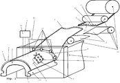
- Fig. 1 is a perspective view of a sequence of the production of a coated plastic element 1 according to an embodiment of the invention schematically and greatly simplified and not shown to scale.
- body parts and add-on parts on a vehicle have usually been painted so far.
- the surfaces of such body paints in a vehicle and the painted surfaces of add-on parts made of plastic show a pronounced structure on the surface depending on the painting process. In general usage, this structure is referred to as the so-called orange peel in specialist circles.
- an extruded add-on part can be produced in high-gloss black or in the respective body color by means of a paint transfer film. In this case, the parts no longer have to be painted in an additional operation as before. Instead, the lacquer-like surface can be produced by a lacquer transfer film.
- a coated plastic element 1 is produced which is coated with a lacquer film 2 of a lacquer transfer film 3 and has a structured surface, the structured surface, for example, having a structure or orange peel structure that is as similar as possible to a lacquered surface.
- the plastic element 1 is produced entirely as an extrusion part 23 from a plastic material 14 by means of an extrusion process.
- the plastic element can also be produced only partially as an extrusion part or an extrusion part with an additional base, as in the following Fig. 3 is shown.
- a base for example a metal profile, is provided with the extrusion part in at least one section, for example on its outside or visible side.
- the base is coated with the plastic material 14 in the at least one section by the extrusion process.
- the plastic material 14 consists of a plastic or a combination of at least two plastics.
- polyurethane and in particular a partially crosslinked polyurethane or a polyurethane which is not thermally deformable or thermally deformable as little as possible can be used as the plastic.
- the invention is not limited to polyurethane as a plastic. Any other plastic or combination of plastics can be used which is or are suitable for producing a plastic element 1 as an extrusion part and in particular an attachment part of a vehicle, which is coated with a paint film 2 of a paint transfer film 3.
- the plastic element 1 can be designed as an add-on part for a vehicle, for example as a cover or strip, roof strip or water deflector, shaft strip, vehicle window surround, etc.
- the plastic material 14 made of at least one plastic is melted, for example continuously melted, and discharged through a shaping nozzle 4 of an extrusion device 5, as in FIG Fig. 1 is greatly simplified and not shown to scale.
- the shaping nozzle 4 is used as an attachment for a vehicle in Fig. 1
- a strip 6 or cover is designed as a plastic element 1.
- the plastic element 1 can also be made only partially from the plastic material 14, for example, instead of completely from the plastic material 14.
- the plastic element can have a base, for example a metal profile made of aluminum, an aluminum alloy or steel, etc., which is coated in at least one section with the plastic material 14 by extrusion to form the plastic element as an extrusion part with a base.
- the section of the plastic element coated with the plastic material by extrusion is then coated on its outside with a paint film of a paint transfer film to form the finished coated plastic element.
- the base for example a metal profile
- the base is fed to the extrusion device via a base feed device (not shown) and the base is coated with the plastic material by means of the extrusion device.
- the extrusion part is then coated with the lacquer film and forms a structured surface through the particles added to the plastic material and / or through structuring with a structuring device described in more detail below.
- the coating of the extrusion part with the lacquer film can take place immediately or at a later point in time after leaving the extrusion device in which the extrusion part is formed.
- the extrusion can be coated after a subsequent cooling bath for the extrusion.
- the invention is not limited to the examples mentioned at the time the lacquer film is laminated onto the extrusion part.
- the lacquer film can be applied or laminated onto the extrusion part at any other suitable point in time. The same applies to a structuring of the lacquer film by a structuring device to be described in more detail.
- the lacquer film can be applied to the extrusion part by the structuring device, such as a grain roller, a sprinkling and / or spray nozzle device, immediately or at a later point in time after leaving the extrusion device and structured by the structuring device. Likewise, after a subsequent cooling bath for the extruded part, the lacquer film can also be applied to the latter and structured by the structuring device.
- the structuring of the lacquer film can take place immediately after it has been applied or laminated to the extrusion part or in a subsequent work step.
- the aforementioned particles are mixed into the plastic material 14 of the plastic element 1 according to one embodiment of the invention.
- the particles introduced into the plastic element 1 are in Fig. 1 not shown for reasons of clarity.
- the particles consist of a material or a combination of materials which does not or as little as possible melts or melts in the plastic material. Therefore, the particles form as in the following Fig. 2 is shown, with the plastic material, a structured surface which, when additionally coated with the lacquer film 2, forms an orange peel or a structure as similar as possible to a lacquered surface.
- the plastic or plastic material 14 below the paint film 2 is modified by at least one suitable additive in the form of non-melting or only slightly melting particles.
- This addition of particles creates a surface structure in the plastic, which is transferred to or reproduced on the paint film 2 of the paint transfer film 3 after the plastic element 1 has been coated with this film 2, as in the following Fig. 2 is indicated, so that a surface similar to the orange peel structure or the structure of a painted surface is generated.
- the structure of the extrudate or extrusion part and thus of the plastic element 1 can be specifically influenced by the type of modifying substance and the amount of addition.
- the particles used can be, for example, cross-linked particles and thus non-melting particles made of polyvinyl chloride (PVC) or cross-linked rubber particles, wood particles, particles made of at least one duromer or thermoset, such as epoxy resin, polyurethane, etc., particles made of a mineral material, talc, chalk, Glass, in particular glass spheres, ceramic, polyamide, metal, etc.
- PVC polyvinyl chloride
- the plastic material can have a proportion in a range of 20% to 30% of particles.
- the invention is not limited to this proportion in a range from 20% to 30% of particles. Depending on the function and intended use, the proportion can also be less than 20%.
- the particles can be made of the same material or at least two different materials, and the same size or diameter or at least two different sizes or diameters can be added to the plastic material.
- the particles In order to form the extrusion part 23 or plastic element 1 with a structure as similar as possible to an orange peel or a lacquered surface, the particles have, for example, a diameter in a range from 40 ⁇ m to 60 ⁇ m and preferably from 45 ⁇ m to 55 ⁇ m and particularly preferably from 50 ⁇ m +/- 4 ⁇ m on.
- the size or the diameter of the particles can be selected as desired, depending on the desired embossing or structure of the surface of the extrusion part 23 or plastic element 1. The thicker the paint film of the paint transfer film, the weaker and softer the structure or embossing of the surface of the extrusion part 23 or Plastic element 1 shown.
- the thinner the lacquer transfer film the stronger and more sharply the structure or embossing of the surface of the extrusion part 23 or plastic element 1 is in turn reproduced. Accordingly, by choosing the size or the diameter of the particles and the thickness of the lacquer film, the structure of the surface of the extrusion part 23 or plastic element provided with the lacquer film can be set in a targeted manner.
- the characteristics of e.g. orange peel or a structure that is as similar as possible to a painted surface can be specifically influenced or adjusted by choosing the diameter or size of the particles.
- An extrusion device 5 is used in the production of the extrusion part 23 or plastic element 1 by extrusion.
- a screw extruder for example a single-screw extruder or a twin-screw extruder, or a piston extruder can be used as the extrusion device 5.
- the pressure is generated by means of a piston.
- Piston extruders are mainly used if the material to be processed cannot be processed using screw extruders or if a frequent product change is to be carried out.
- the invention is not restricted to the examples given for extrusion devices.
- the running speed of the extrusion part 23 or plastic element 1 from the shaping nozzle 4 of the extrusion device 5 is in a range of preferably 10 ° m / min to 15 ° m / min. If a single-screw extruder is used as the extrusion device 5, the rotational speed of the extrusion screw of the single-screw extruder 5 is in a range of preferably 5 ° rpm to 25 ° rpm.
- the lacquer transfer film 3 has an optional carrier layer 11 and an optional additional protective layer 24.
- the carrier layer 11 is arranged on the underside of the lacquer film 2 and the protective layer 24 is arranged on the upper side of the lacquer film 2.
- the carrier layer 11 is peeled off the lacquer film 2 before the coating of the later extrusion part in front of the extrusion device 5.
- the protective layer 24 initially remains on the lacquer film 2 and, as in FIG Fig. 1 is shown, for example applied to the extrusion part 23 together with the lacquer film 2 and only removed from the lacquer film 2 in a later step in order to provide the finished plastic element 1 coated with the lacquer film 2.
- the lacquer film 2 and, if present, the additional protective layer 24 of the lacquer transfer film 3 after the extrusion part 23 or plastic element 1 has left the shaping nozzle 4 of the extrusion device 5, is applied to a surface area of the extrusion part 23 or plastic element 1 to be coated by a coating device 15 applied.
- the lacquer film 2 and, if present, the additional protective layer 24 of the lacquer transfer film 3, for example directly after leaving the shaping nozzle 4, is applied to the extrusion part 23 or the plastic element 1 by the coating device, as long as the extrusion part 23 or plastic element is still warm and then the extrusion part 23 or plastic element 1 coated with the lacquer film 2 and, if present, an additional protective layer 24 is cooled.
- the extrusion part 23 or plastic element 1 coated with the lacquer film 2 and, if present, the additional protective layer 24 of the lacquer transfer film 3 can cool at room temperature or be cooled by means of an additional cooling device, not shown.
- the lacquer film 2 and, if present, the additional protective layer 24 can, instead of being applied to the extrusion part 23 or plastic element 1 directly after leaving the shaping nozzle 4, also be applied later to the extrusion part 23 or plastic element 1, for example before, during and / or after the extrusion part 23 or plastic element 1 has cooled down. While the lacquer film 2 remains on the extrusion part 23 to provide the finished plastic element 1, the protective layer 24, if present, is removed or peeled off from the lacquer film 2.
- an extrusion part with a metal base for example, this can be done after a stretch-bending process, in which the extrusion part coated with the lacquer film 2 and the protective layer 24 was brought into a desired shape with its metal base by the stretch-bending process.
- the protective layer 24 can also be applied to any be peeled off from the lacquer film 2 at another suitable time. This can take place before the extrusion tool or after leaving the extrusion tool, for example immediately after leaving the extrusion tool, before or after the structuring of the paint film by the structuring device, before or after the extrusion part has cooled, etc.
- the invention is not limited to the examples mentioned limited.
- the carrier layer (11) and the protective layer (24) can be made from the same material or different materials, depending on the function and intended use.
- the coating device 15 can for example have rollers or doctor blades, not shown, as in FIG Fig. 1 is indicated by arrows P, by means of which the lacquer film 2 of the lacquer transfer film 3 can be applied to the extrusion part 23 or plastic element 1.
- any other coating device 15 can also be provided which is suitable for applying or applying the lacquer film 2 to at least one section of the extrusion part 23.
- the extrusion part 23 or plastic element 1 can be provided with an orange peel or with a structure that is as similar as possible to a painted surface by the surface of the Extrusion part 23 or plastic element 1 is structured by an aforementioned structuring device 7.
- At least one grain roller 8 is provided as an example and purely schematically, which provides the surface of the extrusion part 23 or plastic element 1 coated with the lacquer film 2 with, for example, an orange peel or a structure as similar as possible to a lacquered surface.
- the grain roller 8 has a correspondingly profiled or structured surface 9, as in FIG Fig. 1 is shown greatly simplified.
- a sprinkling and / or spray nozzle device 10 can be provided as structuring device 7, as also in FIG Fig. 1 is shown greatly simplified.
- the sprinkling and / or spray nozzle device 10 is designed such that the surface of the extrusion part 23 or plastic element 1 coated with the lacquer film 2 of the lacquer transfer film 3 can be sprinkled with a fluid or steam, e.g. water or steam, and / or with at least one or more Nozzles, not shown, direct a nozzle jet, in particular a fluid jet or gas jet, onto the surface coated with the lacquer film 2 in order to structure the surface.
- the surface structured in this way preferably has an orange-skin structure or a structure that is as similar as possible to a lacquered surface.
- the lacquer transfer film 3 has the lacquer film 2, a protective layer 24 and a carrier layer 11, as in FIG Fig. 1 is shown as an example.
- the lacquer film 2 can Lacquer transfer film 3 have one layer or several layers in order to achieve, for example, a certain gloss effect, in particular a high gloss effect, a metal effect, matt effect, color effect, image effect of the structure or embossing of the surface of the extrusion part 23 or plastic element, etc.
- the paint transfer film can also be provided with the aforementioned additional protective layer 24, which is provided on the top of the paint film 2 of the paint transfer film 3 in order to protect the paint film.
- this protective layer 24 can be removed again before or after the lacquer film 2 is applied to the plastic element.
- the carrier layer 11 for the lacquer film of the lacquer transfer film 3 is removed before the lacquer film is applied to the plastic element.
- This paint transfer film 3 is fed to the extrusion device 5 by a film feed device 12 and the carrier layer 11 is removed or peeled off from the paint film 2 by the film feed device 12 before the paint film 2 is applied to the extrusion part 23 or plastic element 1 by the coating device .
- the lacquer film 2 of the lacquer transfer film 3 is in Fig. 1 indicated with a dotted line. Examples of lacquer transfer foils as they can be used in the invention are produced, for example, by Wörwag and Akzo.
- the protective layer 24 is in the example in FIG Fig. 1 indicated with a dashed line and is removed from the lacquer film 2, for example after leaving the extrusion device 5, for example before the lacquer film 2 is structured by the structuring device.
- the lacquer film 2 can have both at least one black colored layer and at least one layer colored in a predetermined lacquer color, corresponding to the lacquer color of a lacquered body part to which the plastic element 1 is then attached, for example.
- both a black and a colored, including white, coated plastic element 1 can be produced as an add-on part for a vehicle.
- the lacquer film can have a glossy, in particular high-gloss, matt and / or metallic design in order to produce a correspondingly coated plastic element 1.
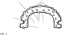
- FIG. 13 is a greatly simplified, purely schematic and not to scale sectional view through the plastic element 1 according to FIG. 1 coated with the lacquer film 2 of a lacquer transfer film Fig. 1 shown.
- the plastic element 1 in this embodiment according to the invention is designed entirely as an extrusion part 23 and is additionally coated with the lacquer film 2.
- the plastic material 14 of the extrusion part 23 or plastic element 1 particles 13 are mixed.
- the particles 13 consist of a material or a combination of materials that does not melt with the plastic material 14 in the extrusion device or only melts with it as little as possible in the extrusion device, so that a structured surface and not a smooth surface is produced.
- the particles 13, as in FIG Fig. 2 is shown, produce a structured surface with the extrusion part 23 or plastic element 1, instead of a completely smooth surface.
- the lacquer film 2 of the lacquer transfer film applied to the structured surface of the extrusion part 23 or plastic element 1 forms the structured surface of the extrusion part 23 or plastic element 1, so that a plastic element 1 can be produced with a surface coated with the lacquer film 2, which for example has an orange skin structure or a structure that is as similar as possible to a painted surface.
- the lacquer film 2 of the lacquer transfer film is in Fig. 2 also indicated with a dotted line.
- Fig. 3 is a greatly simplified, purely schematic and not to scale sectional view through a plastic element 1 coated with a paint film 2 of a paint transfer film according to a further exemplary embodiment of the invention.
- the plastic element 1 according to Fig. 3 differs from the plastic element in the Fig. 1 and 2 in that the plastic element 1 is not completely made as an extrusion part but only partially as an extrusion part 23 from a plastic material 14 made of at least one plastic.
- the plastic element 1 in the embodiment in Fig. 3 has a base 16, for example a metal profile made of aluminum, an aluminum alloy or steel etc., which is provided or coated with the extrusion part 23.
- the invention is not limited to a base 16 made of metal.
- the base 16 can also be made from any other material or material combination which is suitable for being coated by extrusion with a plastic material made of at least one plastic to form a plastic element 1 as an extrusion part 23 with a base.
- At least a portion of the base 16 is extruded, as previously exemplified with reference to FIG Fig. 1 and 2 has been described, coated with the plastic material 14 to form the extrusion part 23, with the plastic material 14 for the later formation of a structured surface optionally additionally particles 13 can be added, as previously also by way of example with reference to FIG Fig. 1 and 2 has been described. To avoid unnecessary repetition, refer to the description in Fig. 1 and 2 referenced.
- the in Fig. 3 The embodiment shown is, for example, the visible side or top of the base 16 made of an aluminum alloy coated by extrusion with the plastic material 14 made of at least one plastic.
- additional particles 13, for example are added to the plastic material 14.
- the embodiment shown are particles 13, for example in the form of spheres with a structure for generating a Surface suitable or predetermined diameter made of a material or a combination of materials, which does not or as little as possible in the plastic material melts or melts.
- the particles 13 in the form of beads can, as previously with reference to FIG Fig.
- PVC polyvinyl chloride
- wood from at least one duromer or thermosetting plastic, such as epoxy resin, polyurethane, etc., from a mineral material, talc, chalk, glass, ceramic, polyamide, metal, etc .. made be.
- the invention is not limited to the materials mentioned for the particles.
- any other material or combination of materials can also be used which is suitable for being mixed with the plastic material for the extrusion part 23 of the plastic element in order to produce a desired surface structure.
- a lacquer film 2 of a lacquer transfer film is applied, as previously exemplified with reference to FIG Fig. 1 and 2 has been described.
- the lacquer film 2 is also indicated with a dotted line.
- the extrusion part 23 of the plastic element 1 coated with the lacquer film 23 can also be structured by means of a structuring device, for example a grain roller, etc., as described above with reference to FIG Fig. 1 and 2 has been described.
- coated plastic elements 1 shown can be provided on a vehicle, for example, as a cover or strip, for example a roof strip, etc.
- a coated plastic element 1 with a base 16, in particular made of an aluminum alloy, has the advantage that it can later be bent if necessary, for example to run as a roof rail along the roof and at least along one of the vehicle pillars.
- Such a cover or strip, in particular a roof strip in a vehicle can have one or more additional components as a coated plastic element 1, each of which is a coated plastic part or plastic element according to FIG Fig. 1 , 2 , or 3 are formed and preferably do not differ optically or as little as possible from the roof strip as a coated plastic element 1.
- this additional component can be, for example, a flap element for opening and closing an opening in the roof molding. The flap element can be folded into the open position, for example outwards, in order to expose an opening in the roof molding, for mounting elements such as roof racks etc. on the vehicle.
- the additional component can, like the roof rail, as a coated plastic element 1, as previously with reference to the Figs. 1 to 3 is described.
- the additional component can be designed as a coated plastic part 17, as in FIG Fig. 4 is indicated purely schematically and greatly simplified.
- Fig. 4 shows a sectional view of an injection mold 18 for producing a coated plastic part 17 as an additional component.
- the injection mold has two mold halves 19, 20.
- the embodiment shown is a section of the inside of one of the mold halves 19 is provided with a structure 21 to produce a structured surface on the plastic part 17.
- the lacquer film 2 is pressed against the structured inside of the mold half 19 in order to provide the plastic part 17 to be produced with a structured surface.
- the finished plastic part 17 coated with the lacquer film 2 can be provided with a surface structure which has a structure that is as similar as possible to an orange peel or a lacquered surface.
- the lacquer film 2 can have at least one or more layers.
- the coated plastic part 17 can be produced by a one-component injection molding process or by a multi-component injection molding process.
- add-on parts for a vehicle can be produced as plastic element 1.
- plastic element 1 As described above, add-on parts for a vehicle, such as panels or strips, for example roof strips, vehicle window frames, etc., can be produced as plastic element 1.
- Fig. 1 , 2 and 3 The shape shown of the plastic element 1 and its cross section is purely exemplary and the invention is not limited thereto. Any shape and any cross-section can be produced, which can in particular be produced by an extrusion device.
- the invention is also not limited to the in Fig. 3 Shown special embodiment of the plastic element from the extrusion and base limited.
- the base can have any profile, depending on the function and intended use.
- the extrusion part can be shaped as desired or the base can be coated with it, depending on the function and intended use.
Landscapes
- Engineering & Computer Science (AREA)
- Mechanical Engineering (AREA)
- Extrusion Moulding Of Plastics Or The Like (AREA)
Applications Claiming Priority (3)
| Application Number | Priority Date | Filing Date | Title |
|---|---|---|---|
| DE102015211086.9A DE102015211086B4 (de) | 2015-06-17 | 2015-06-17 | Kunststoffelement, Herstellvorrichtung und Verfahren zum Herstellen des Kunststoffelements |
| PCT/EP2016/063725 WO2016202845A2 (fr) | 2015-06-17 | 2016-06-15 | Élément en matière plastique, dispositif de fabrication et procédé de fabrication de l'élément en matière plastique |
| EP16731550.6A EP3310548A2 (fr) | 2015-06-17 | 2016-06-15 | Élément en matière plastique, dispositif de fabrication et procédé de fabrication de l'élément en matière plastique |
Related Parent Applications (1)
| Application Number | Title | Priority Date | Filing Date |
|---|---|---|---|
| EP16731550.6A Division EP3310548A2 (fr) | 2015-06-17 | 2016-06-15 | Élément en matière plastique, dispositif de fabrication et procédé de fabrication de l'élément en matière plastique |
Publications (2)
| Publication Number | Publication Date |
|---|---|
| EP3766660A1 true EP3766660A1 (fr) | 2021-01-20 |
| EP3766660B1 EP3766660B1 (fr) | 2023-08-09 |
Family
ID=56194454
Family Applications (2)
| Application Number | Title | Priority Date | Filing Date |
|---|---|---|---|
| EP20195886.5A Active EP3766660B1 (fr) | 2015-06-17 | 2016-06-15 | Élément en matière plastique, dispositif de fabrication et procédé de fabrication d'élément en matière plastique |
| EP16731550.6A Withdrawn EP3310548A2 (fr) | 2015-06-17 | 2016-06-15 | Élément en matière plastique, dispositif de fabrication et procédé de fabrication de l'élément en matière plastique |
Family Applications After (1)
| Application Number | Title | Priority Date | Filing Date |
|---|---|---|---|
| EP16731550.6A Withdrawn EP3310548A2 (fr) | 2015-06-17 | 2016-06-15 | Élément en matière plastique, dispositif de fabrication et procédé de fabrication de l'élément en matière plastique |
Country Status (5)
| Country | Link |
|---|---|
| EP (2) | EP3766660B1 (fr) |
| CN (1) | CN107921689B (fr) |
| DE (1) | DE102015211086B4 (fr) |
| MX (1) | MX2017016193A (fr) |
| WO (1) | WO2016202845A2 (fr) |
Families Citing this family (5)
| Publication number | Priority date | Publication date | Assignee | Title |
|---|---|---|---|---|
| DE102017209457A1 (de) * | 2017-06-02 | 2018-12-06 | Faurecia Innenraum Systeme Gmbh | Verfahren und Werkzeug zum Herstellen eines Fahrzeuginnenverkleidungsteils sowie Fahrzeuginnenverkleidungsteil |
| EP3542989A1 (fr) * | 2018-03-20 | 2019-09-25 | Motherson Innovations Company Limited | Composant en matière plastique et procédé de fabrication du composant en matière plastique |
| CN114274401B (zh) * | 2021-12-31 | 2024-06-21 | 连云港永泰塑业有限公司 | 一种尼龙再生塑料颗粒及其制备方法 |
| CN115447014A (zh) * | 2022-09-20 | 2022-12-09 | 王朝霞 | 一种塑料粒子制备工艺 |
| DE102023210371A1 (de) * | 2023-10-20 | 2025-04-24 | Volkswagen Aktiengesellschaft | Zierleiste sowie Verfahren zur Herstellung einer solchen |
Citations (3)
| Publication number | Priority date | Publication date | Assignee | Title |
|---|---|---|---|---|
| JPS53145866A (en) * | 1977-05-26 | 1978-12-19 | Aron Kasei Kk | Decorative material production method |
| GB2074092A (en) * | 1980-03-26 | 1981-10-28 | Schiesser Ag | Method and apparatus for equipping profiles formed of elastic masses with velour bands |
| DE102012023066A1 (de) | 2012-11-26 | 2014-05-28 | Volkswagen Aktiengesellschaft | Foliendekoriertes Kunststoff-Formteil sowie Verfahren zur Herstellung eines solchen Formteiles |
Family Cites Families (5)
| Publication number | Priority date | Publication date | Assignee | Title |
|---|---|---|---|---|
| DE2908487A1 (de) | 1979-03-05 | 1980-09-11 | Roehm Gmbh | Extrudierter hohlprofilstrang aus thermoplastischem kunststoff mit oberflaechenstruktur |
| US7067188B1 (en) | 1999-01-21 | 2006-06-27 | Arkema | Polymeric articles having a textured surface and frosted appearance |
| DE10329938A1 (de) * | 2003-07-02 | 2005-03-17 | Röhm GmbH & Co. KG | Kunststoffkörper mit mikrostrukturierter Oberfläche |
| CN101247954B (zh) * | 2005-08-23 | 2011-09-28 | 优泊公司 | 树脂薄膜及其制造方法、印刷品、标签及树脂成形品 |
| PL220970B1 (pl) * | 2013-03-22 | 2016-02-29 | Polska Ekstruzja Spółka Z Ograniczoną Odpowiedzialnością | Sposób nakładania okładziny zewnętrznej na profile PVC i urządzenie do nakładania okładziny zewnętrznej na profile PVC |
-
2015
- 2015-06-17 DE DE102015211086.9A patent/DE102015211086B4/de not_active Expired - Fee Related
-
2016
- 2016-06-15 EP EP20195886.5A patent/EP3766660B1/fr active Active
- 2016-06-15 WO PCT/EP2016/063725 patent/WO2016202845A2/fr not_active Ceased
- 2016-06-15 CN CN201680048137.1A patent/CN107921689B/zh not_active Expired - Fee Related
- 2016-06-15 MX MX2017016193A patent/MX2017016193A/es unknown
- 2016-06-15 EP EP16731550.6A patent/EP3310548A2/fr not_active Withdrawn
Patent Citations (3)
| Publication number | Priority date | Publication date | Assignee | Title |
|---|---|---|---|---|
| JPS53145866A (en) * | 1977-05-26 | 1978-12-19 | Aron Kasei Kk | Decorative material production method |
| GB2074092A (en) * | 1980-03-26 | 1981-10-28 | Schiesser Ag | Method and apparatus for equipping profiles formed of elastic masses with velour bands |
| DE102012023066A1 (de) | 2012-11-26 | 2014-05-28 | Volkswagen Aktiengesellschaft | Foliendekoriertes Kunststoff-Formteil sowie Verfahren zur Herstellung eines solchen Formteiles |
Also Published As
| Publication number | Publication date |
|---|---|
| DE102015211086A1 (de) | 2016-12-22 |
| DE102015211086B4 (de) | 2023-11-02 |
| EP3766660B1 (fr) | 2023-08-09 |
| WO2016202845A3 (fr) | 2017-02-09 |
| CN107921689A (zh) | 2018-04-17 |
| MX2017016193A (es) | 2018-06-27 |
| EP3310548A2 (fr) | 2018-04-25 |
| WO2016202845A2 (fr) | 2016-12-22 |
| CN107921689B (zh) | 2021-04-06 |
Similar Documents
| Publication | Publication Date | Title |
|---|---|---|
| EP3766660B1 (fr) | Élément en matière plastique, dispositif de fabrication et procédé de fabrication d'élément en matière plastique | |
| DE69620488T2 (de) | Extrudierter Gegenstand mit dekorativer Verbesserung und Verfahren. | |
| DE102007036197B4 (de) | Kunststoff-Formteil | |
| DE4032160A1 (de) | Vorrichtung zum aufbringen eines kunststoffueberzuges | |
| EP4052612B1 (fr) | Baguette de bordure et son procédé de fabrication | |
| DE102011016757B4 (de) | Verfahren zur Herstellung eines Kunststoffverbundbauteils | |
| DE102007058714B4 (de) | Verfahren zum Herstellen eines Bauteils und Bauteil für ein Kraftfahrzeug | |
| DE3640887A1 (de) | Verfahren zur einbringung von extrudierbaren dichtungsprofilen | |
| EP0759351B1 (fr) | Méthode et appareil pour la production de feuilles de tableau de bord avec deux ou plusieurs couleurs ou tableau de bord fabriqué à partir de telles feuilles | |
| EP2519390B1 (fr) | Peau de moulage et procédé destiné à sa fabrication | |
| DE69407815T2 (de) | Verfahren zum formen und mit diesem verfahren hergestelltes formteil | |
| DE102020202535A1 (de) | Kraftfahrzeugtürabdichtelement und verfahren zur herstellung desselben | |
| DE102005028355A1 (de) | Innenverkleidungsteil für Kraftfahrzeuge sowie Verfahren zur Herstellung eines Innenverkleidungsteils | |
| WO1995012483A1 (fr) | Technique et dispositif de fabrication de produits multicouches par extrusion et pultrusion ainsi qu'utilisation de la matiere coextrudee au moyen dudit dispositif | |
| EP1743756A1 (fr) | Procédé de fabrication d'un élément composite | |
| DE102012014659A1 (de) | Kunststoffbauteil, insbesondere für ein Kraftfahrzeug und Verfahren zur Herstellung eines Kunststoffbauteils | |
| DE102004012937A1 (de) | Verfahren zur Herstellung eines Verbundmaterials | |
| DE19736194A1 (de) | Mehrfarbige Verbundfolie aus thermoplastischem Kunststoff und Verfahren und Vorrichtung für ihre Herstellung | |
| DE1948442C3 (de) | Verfahren und Vorrichtung zum Strangpressen einer Verbundfolie aus thermoplastischen Kunststoffen | |
| EP1700714A2 (fr) | Procédé et dispositif de fabrication des corps profilés décorés d'un élément flexible | |
| EP2576173B1 (fr) | Procédé pour générer une peau de moulage dotée d'un décor, procédé pour fabriquer une partie d'habillage intérieure de véhicule | |
| EP3542989A1 (fr) | Composant en matière plastique et procédé de fabrication du composant en matière plastique | |
| EP1957269B1 (fr) | Procede de production de films multicolores | |
| DE102015218142A1 (de) | Verfahren zur Herstellung eines Verbundbauteils | |
| EP3683032A1 (fr) | Procédé de fabrication d'une boîte aux lettres |
Legal Events
| Date | Code | Title | Description |
|---|---|---|---|
| PUAI | Public reference made under article 153(3) epc to a published international application that has entered the european phase |
Free format text: ORIGINAL CODE: 0009012 |
|
| STAA | Information on the status of an ep patent application or granted ep patent |
Free format text: STATUS: REQUEST FOR EXAMINATION WAS MADE |
|
| 17P | Request for examination filed |
Effective date: 20200914 |
|
| AC | Divisional application: reference to earlier application |
Ref document number: 3310548 Country of ref document: EP Kind code of ref document: P |
|
| AK | Designated contracting states |
Kind code of ref document: A1 Designated state(s): AL AT BE BG CH CY CZ DE DK EE ES FI FR GB GR HR HU IE IS IT LI LT LU LV MC MK MT NL NO PL PT RO RS SE SI SK SM TR |
|
| GRAP | Despatch of communication of intention to grant a patent |
Free format text: ORIGINAL CODE: EPIDOSNIGR1 |
|
| STAA | Information on the status of an ep patent application or granted ep patent |
Free format text: STATUS: GRANT OF PATENT IS INTENDED |
|
| INTG | Intention to grant announced |
Effective date: 20230306 |
|
| GRAS | Grant fee paid |
Free format text: ORIGINAL CODE: EPIDOSNIGR3 |
|
| GRAA | (expected) grant |
Free format text: ORIGINAL CODE: 0009210 |
|
| STAA | Information on the status of an ep patent application or granted ep patent |
Free format text: STATUS: THE PATENT HAS BEEN GRANTED |
|
| P01 | Opt-out of the competence of the unified patent court (upc) registered |
Effective date: 20230620 |
|
| AC | Divisional application: reference to earlier application |
Ref document number: 3310548 Country of ref document: EP Kind code of ref document: P |
|
| AK | Designated contracting states |
Kind code of ref document: B1 Designated state(s): AL AT BE BG CH CY CZ DE DK EE ES FI FR GB GR HR HU IE IS IT LI LT LU LV MC MK MT NL NO PL PT RO RS SE SI SK SM TR |
|
| REG | Reference to a national code |
Ref country code: GB Ref legal event code: FG4D Free format text: NOT ENGLISH |
|
| REG | Reference to a national code |
Ref country code: CH Ref legal event code: EP |
|
| REG | Reference to a national code |
Ref country code: DE Ref legal event code: R096 Ref document number: 502016016013 Country of ref document: DE |
|
| REG | Reference to a national code |
Ref country code: IE Ref legal event code: FG4D Free format text: LANGUAGE OF EP DOCUMENT: GERMAN |
|
| REG | Reference to a national code |
Ref country code: LT Ref legal event code: MG9D |
|
| REG | Reference to a national code |
Ref country code: NL Ref legal event code: MP Effective date: 20230809 |
|
| PG25 | Lapsed in a contracting state [announced via postgrant information from national office to epo] |
Ref country code: GR Free format text: LAPSE BECAUSE OF FAILURE TO SUBMIT A TRANSLATION OF THE DESCRIPTION OR TO PAY THE FEE WITHIN THE PRESCRIBED TIME-LIMIT Effective date: 20231110 |
|
| PG25 | Lapsed in a contracting state [announced via postgrant information from national office to epo] |
Ref country code: IS Free format text: LAPSE BECAUSE OF FAILURE TO SUBMIT A TRANSLATION OF THE DESCRIPTION OR TO PAY THE FEE WITHIN THE PRESCRIBED TIME-LIMIT Effective date: 20231209 |
|
| PG25 | Lapsed in a contracting state [announced via postgrant information from national office to epo] |
Ref country code: SE Free format text: LAPSE BECAUSE OF FAILURE TO SUBMIT A TRANSLATION OF THE DESCRIPTION OR TO PAY THE FEE WITHIN THE PRESCRIBED TIME-LIMIT Effective date: 20230809 Ref country code: RS Free format text: LAPSE BECAUSE OF FAILURE TO SUBMIT A TRANSLATION OF THE DESCRIPTION OR TO PAY THE FEE WITHIN THE PRESCRIBED TIME-LIMIT Effective date: 20230809 Ref country code: PT Free format text: LAPSE BECAUSE OF FAILURE TO SUBMIT A TRANSLATION OF THE DESCRIPTION OR TO PAY THE FEE WITHIN THE PRESCRIBED TIME-LIMIT Effective date: 20231211 Ref country code: NO Free format text: LAPSE BECAUSE OF FAILURE TO SUBMIT A TRANSLATION OF THE DESCRIPTION OR TO PAY THE FEE WITHIN THE PRESCRIBED TIME-LIMIT Effective date: 20231109 Ref country code: NL Free format text: LAPSE BECAUSE OF FAILURE TO SUBMIT A TRANSLATION OF THE DESCRIPTION OR TO PAY THE FEE WITHIN THE PRESCRIBED TIME-LIMIT Effective date: 20230809 Ref country code: LV Free format text: LAPSE BECAUSE OF FAILURE TO SUBMIT A TRANSLATION OF THE DESCRIPTION OR TO PAY THE FEE WITHIN THE PRESCRIBED TIME-LIMIT Effective date: 20230809 Ref country code: LT Free format text: LAPSE BECAUSE OF FAILURE TO SUBMIT A TRANSLATION OF THE DESCRIPTION OR TO PAY THE FEE WITHIN THE PRESCRIBED TIME-LIMIT Effective date: 20230809 Ref country code: IS Free format text: LAPSE BECAUSE OF FAILURE TO SUBMIT A TRANSLATION OF THE DESCRIPTION OR TO PAY THE FEE WITHIN THE PRESCRIBED TIME-LIMIT Effective date: 20231209 Ref country code: HR Free format text: LAPSE BECAUSE OF FAILURE TO SUBMIT A TRANSLATION OF THE DESCRIPTION OR TO PAY THE FEE WITHIN THE PRESCRIBED TIME-LIMIT Effective date: 20230809 Ref country code: GR Free format text: LAPSE BECAUSE OF FAILURE TO SUBMIT A TRANSLATION OF THE DESCRIPTION OR TO PAY THE FEE WITHIN THE PRESCRIBED TIME-LIMIT Effective date: 20231110 Ref country code: FI Free format text: LAPSE BECAUSE OF FAILURE TO SUBMIT A TRANSLATION OF THE DESCRIPTION OR TO PAY THE FEE WITHIN THE PRESCRIBED TIME-LIMIT Effective date: 20230809 |
|
| PG25 | Lapsed in a contracting state [announced via postgrant information from national office to epo] |
Ref country code: PL Free format text: LAPSE BECAUSE OF FAILURE TO SUBMIT A TRANSLATION OF THE DESCRIPTION OR TO PAY THE FEE WITHIN THE PRESCRIBED TIME-LIMIT Effective date: 20230809 |
|
| PG25 | Lapsed in a contracting state [announced via postgrant information from national office to epo] |
Ref country code: ES Free format text: LAPSE BECAUSE OF FAILURE TO SUBMIT A TRANSLATION OF THE DESCRIPTION OR TO PAY THE FEE WITHIN THE PRESCRIBED TIME-LIMIT Effective date: 20230809 |
|
| PG25 | Lapsed in a contracting state [announced via postgrant information from national office to epo] |
Ref country code: SM Free format text: LAPSE BECAUSE OF FAILURE TO SUBMIT A TRANSLATION OF THE DESCRIPTION OR TO PAY THE FEE WITHIN THE PRESCRIBED TIME-LIMIT Effective date: 20230809 Ref country code: RO Free format text: LAPSE BECAUSE OF FAILURE TO SUBMIT A TRANSLATION OF THE DESCRIPTION OR TO PAY THE FEE WITHIN THE PRESCRIBED TIME-LIMIT Effective date: 20230809 Ref country code: ES Free format text: LAPSE BECAUSE OF FAILURE TO SUBMIT A TRANSLATION OF THE DESCRIPTION OR TO PAY THE FEE WITHIN THE PRESCRIBED TIME-LIMIT Effective date: 20230809 Ref country code: EE Free format text: LAPSE BECAUSE OF FAILURE TO SUBMIT A TRANSLATION OF THE DESCRIPTION OR TO PAY THE FEE WITHIN THE PRESCRIBED TIME-LIMIT Effective date: 20230809 Ref country code: DK Free format text: LAPSE BECAUSE OF FAILURE TO SUBMIT A TRANSLATION OF THE DESCRIPTION OR TO PAY THE FEE WITHIN THE PRESCRIBED TIME-LIMIT Effective date: 20230809 Ref country code: CZ Free format text: LAPSE BECAUSE OF FAILURE TO SUBMIT A TRANSLATION OF THE DESCRIPTION OR TO PAY THE FEE WITHIN THE PRESCRIBED TIME-LIMIT Effective date: 20230809 Ref country code: SK Free format text: LAPSE BECAUSE OF FAILURE TO SUBMIT A TRANSLATION OF THE DESCRIPTION OR TO PAY THE FEE WITHIN THE PRESCRIBED TIME-LIMIT Effective date: 20230809 |
|
| REG | Reference to a national code |
Ref country code: DE Ref legal event code: R097 Ref document number: 502016016013 Country of ref document: DE |
|
| PG25 | Lapsed in a contracting state [announced via postgrant information from national office to epo] |
Ref country code: IT Free format text: LAPSE BECAUSE OF FAILURE TO SUBMIT A TRANSLATION OF THE DESCRIPTION OR TO PAY THE FEE WITHIN THE PRESCRIBED TIME-LIMIT Effective date: 20230809 |
|
| PLBE | No opposition filed within time limit |
Free format text: ORIGINAL CODE: 0009261 |
|
| STAA | Information on the status of an ep patent application or granted ep patent |
Free format text: STATUS: NO OPPOSITION FILED WITHIN TIME LIMIT |
|
| 26N | No opposition filed |
Effective date: 20240513 |
|
| PG25 | Lapsed in a contracting state [announced via postgrant information from national office to epo] |
Ref country code: SI Free format text: LAPSE BECAUSE OF FAILURE TO SUBMIT A TRANSLATION OF THE DESCRIPTION OR TO PAY THE FEE WITHIN THE PRESCRIBED TIME-LIMIT Effective date: 20230809 |
|
| PG25 | Lapsed in a contracting state [announced via postgrant information from national office to epo] |
Ref country code: BG Free format text: LAPSE BECAUSE OF FAILURE TO SUBMIT A TRANSLATION OF THE DESCRIPTION OR TO PAY THE FEE WITHIN THE PRESCRIBED TIME-LIMIT Effective date: 20230809 |
|
| PG25 | Lapsed in a contracting state [announced via postgrant information from national office to epo] |
Ref country code: BG Free format text: LAPSE BECAUSE OF FAILURE TO SUBMIT A TRANSLATION OF THE DESCRIPTION OR TO PAY THE FEE WITHIN THE PRESCRIBED TIME-LIMIT Effective date: 20230809 |
|
| REG | Reference to a national code |
Ref country code: DE Ref legal event code: R119 Ref document number: 502016016013 Country of ref document: DE |
|
| PG25 | Lapsed in a contracting state [announced via postgrant information from national office to epo] |
Ref country code: MC Free format text: LAPSE BECAUSE OF FAILURE TO SUBMIT A TRANSLATION OF THE DESCRIPTION OR TO PAY THE FEE WITHIN THE PRESCRIBED TIME-LIMIT Effective date: 20230809 |
|
| REG | Reference to a national code |
Ref country code: CH Ref legal event code: PL |
|
| PG25 | Lapsed in a contracting state [announced via postgrant information from national office to epo] |
Ref country code: LU Free format text: LAPSE BECAUSE OF NON-PAYMENT OF DUE FEES Effective date: 20240615 |
|
| GBPC | Gb: european patent ceased through non-payment of renewal fee |
Effective date: 20240615 |
|
| PG25 | Lapsed in a contracting state [announced via postgrant information from national office to epo] |
Ref country code: DE Free format text: LAPSE BECAUSE OF NON-PAYMENT OF DUE FEES Effective date: 20250101 |
|
| PG25 | Lapsed in a contracting state [announced via postgrant information from national office to epo] |
Ref country code: IE Free format text: LAPSE BECAUSE OF NON-PAYMENT OF DUE FEES Effective date: 20240615 |
|
| PG25 | Lapsed in a contracting state [announced via postgrant information from national office to epo] |
Ref country code: CH Free format text: LAPSE BECAUSE OF NON-PAYMENT OF DUE FEES Effective date: 20240630 Ref country code: BE Free format text: LAPSE BECAUSE OF NON-PAYMENT OF DUE FEES Effective date: 20240630 |
|
| PG25 | Lapsed in a contracting state [announced via postgrant information from national office to epo] |
Ref country code: FR Free format text: LAPSE BECAUSE OF NON-PAYMENT OF DUE FEES Effective date: 20240630 |
|
| PG25 | Lapsed in a contracting state [announced via postgrant information from national office to epo] |
Ref country code: GB Free format text: LAPSE BECAUSE OF NON-PAYMENT OF DUE FEES Effective date: 20240615 |
|
| REG | Reference to a national code |
Ref country code: BE Ref legal event code: MM Effective date: 20240630 |
|
| REG | Reference to a national code |
Ref country code: AT Ref legal event code: MM01 Ref document number: 1597002 Country of ref document: AT Kind code of ref document: T Effective date: 20240615 |
|
| PG25 | Lapsed in a contracting state [announced via postgrant information from national office to epo] |
Ref country code: AT Free format text: LAPSE BECAUSE OF NON-PAYMENT OF DUE FEES Effective date: 20240615 |
|
| PG25 | Lapsed in a contracting state [announced via postgrant information from national office to epo] |
Ref country code: CY Free format text: LAPSE BECAUSE OF FAILURE TO SUBMIT A TRANSLATION OF THE DESCRIPTION OR TO PAY THE FEE WITHIN THE PRESCRIBED TIME-LIMIT; INVALID AB INITIO Effective date: 20160615 |
|
| PG25 | Lapsed in a contracting state [announced via postgrant information from national office to epo] |
Ref country code: HU Free format text: LAPSE BECAUSE OF FAILURE TO SUBMIT A TRANSLATION OF THE DESCRIPTION OR TO PAY THE FEE WITHIN THE PRESCRIBED TIME-LIMIT; INVALID AB INITIO Effective date: 20160615 |