EP3770697A1 - Procede de fabrication d'une pierre biseautee, notamment pour un mouvement d'horlogerie - Google Patents
Procede de fabrication d'une pierre biseautee, notamment pour un mouvement d'horlogerie Download PDFInfo
- Publication number
- EP3770697A1 EP3770697A1 EP19188535.9A EP19188535A EP3770697A1 EP 3770697 A1 EP3770697 A1 EP 3770697A1 EP 19188535 A EP19188535 A EP 19188535A EP 3770697 A1 EP3770697 A1 EP 3770697A1
- Authority
- EP
- European Patent Office
- Prior art keywords
- stone
- face
- groove
- precursor
- machining
- Prior art date
- Legal status (The legal status is an assumption and is not a legal conclusion. Google has not performed a legal analysis and makes no representation as to the accuracy of the status listed.)
- Granted
Links
Images


Classifications
-
- G—PHYSICS
- G04—HOROLOGY
- G04B—MECHANICALLY-DRIVEN CLOCKS OR WATCHES; MECHANICAL PARTS OF CLOCKS OR WATCHES IN GENERAL; TIME PIECES USING THE POSITION OF THE SUN, MOON OR STARS
- G04B31/00—Bearings; Point suspensions or counter-point suspensions; Pivot bearings; Single parts therefor
- G04B31/004—Bearings; Point suspensions or counter-point suspensions; Pivot bearings; Single parts therefor characterised by the material used
-
- G—PHYSICS
- G04—HOROLOGY
- G04B—MECHANICALLY-DRIVEN CLOCKS OR WATCHES; MECHANICAL PARTS OF CLOCKS OR WATCHES IN GENERAL; TIME PIECES USING THE POSITION OF THE SUN, MOON OR STARS
- G04B31/00—Bearings; Point suspensions or counter-point suspensions; Pivot bearings; Single parts therefor
- G04B31/06—Manufacture or mounting processes
-
- B—PERFORMING OPERATIONS; TRANSPORTING
- B28—WORKING CEMENT, CLAY, OR STONE
- B28D—WORKING STONE OR STONE-LIKE MATERIALS
- B28D5/00—Fine working of gems, jewels, crystals, e.g. of semiconductor material; apparatus or devices therefor
- B28D5/0058—Accessories specially adapted for use with machines for fine working of gems, jewels, crystals, e.g. of semiconductor material
-
- G—PHYSICS
- G04—HOROLOGY
- G04B—MECHANICALLY-DRIVEN CLOCKS OR WATCHES; MECHANICAL PARTS OF CLOCKS OR WATCHES IN GENERAL; TIME PIECES USING THE POSITION OF THE SUN, MOON OR STARS
- G04B31/00—Bearings; Point suspensions or counter-point suspensions; Pivot bearings; Single parts therefor
- G04B31/02—Shock-damping bearings
-
- B—PERFORMING OPERATIONS; TRANSPORTING
- B22—CASTING; POWDER METALLURGY
- B22F—WORKING METALLIC POWDER; MANUFACTURE OF ARTICLES FROM METALLIC POWDER; MAKING METALLIC POWDER; APPARATUS OR DEVICES SPECIALLY ADAPTED FOR METALLIC POWDER
- B22F3/00—Manufacture of workpieces or articles from metallic powder characterised by the manner of compacting or sintering; Apparatus specially adapted therefor ; Presses and furnaces
- B22F3/12—Both compacting and sintering
- B22F3/16—Both compacting and sintering in successive or repeated steps
- B22F3/162—Machining, working after consolidation
-
- B—PERFORMING OPERATIONS; TRANSPORTING
- B22—CASTING; POWDER METALLURGY
- B22F—WORKING METALLIC POWDER; MANUFACTURE OF ARTICLES FROM METALLIC POWDER; MAKING METALLIC POWDER; APPARATUS OR DEVICES SPECIALLY ADAPTED FOR METALLIC POWDER
- B22F5/00—Manufacture of workpieces or articles from metallic powder characterised by the special shape of the product
- B22F5/10—Manufacture of workpieces or articles from metallic powder characterised by the special shape of the product of articles with cavities or holes, not otherwise provided for in the preceding subgroups
- B22F5/106—Tube or ring forms
-
- B—PERFORMING OPERATIONS; TRANSPORTING
- B28—WORKING CEMENT, CLAY, OR STONE
- B28B—SHAPING CLAY OR OTHER CERAMIC COMPOSITIONS; SHAPING SLAG; SHAPING MIXTURES CONTAINING CEMENTITIOUS MATERIAL, e.g. PLASTER
- B28B3/00—Producing shaped articles from the material by using presses; Presses specially adapted therefor
- B28B3/02—Producing shaped articles from the material by using presses; Presses specially adapted therefor wherein a ram exerts pressure on the material in a moulding space; Ram heads of special form
- B28B3/021—Ram heads of special form
-
- B—PERFORMING OPERATIONS; TRANSPORTING
- B28—WORKING CEMENT, CLAY, OR STONE
- B28D—WORKING STONE OR STONE-LIKE MATERIALS
- B28D1/00—Working stone or stone-like materials, e.g. brick, concrete or glass, not provided for elsewhere; Machines, devices, tools therefor
- B28D1/20—Working stone or stone-like materials, e.g. brick, concrete or glass, not provided for elsewhere; Machines, devices, tools therefor by planing, e.g. channelling by means of planing tools
-
- B—PERFORMING OPERATIONS; TRANSPORTING
- B28—WORKING CEMENT, CLAY, OR STONE
- B28D—WORKING STONE OR STONE-LIKE MATERIALS
- B28D1/00—Working stone or stone-like materials, e.g. brick, concrete or glass, not provided for elsewhere; Machines, devices, tools therefor
- B28D1/22—Working stone or stone-like materials, e.g. brick, concrete or glass, not provided for elsewhere; Machines, devices, tools therefor by cutting, e.g. incising
-
- B—PERFORMING OPERATIONS; TRANSPORTING
- B28—WORKING CEMENT, CLAY, OR STONE
- B28D—WORKING STONE OR STONE-LIKE MATERIALS
- B28D7/00—Accessories specially adapted for use with machines or devices of the preceding groups
-
- B—PERFORMING OPERATIONS; TRANSPORTING
- B28—WORKING CEMENT, CLAY, OR STONE
- B28D—WORKING STONE OR STONE-LIKE MATERIALS
- B28D7/00—Accessories specially adapted for use with machines or devices of the preceding groups
- B28D7/04—Accessories specially adapted for use with machines or devices of the preceding groups for supporting or holding work or conveying or discharging work
-
- C—CHEMISTRY; METALLURGY
- C01—INORGANIC CHEMISTRY
- C01B—NON-METALLIC ELEMENTS; COMPOUNDS THEREOF; METALLOIDS OR COMPOUNDS THEREOF NOT COVERED BY SUBCLASS C01C
- C01B35/00—Boron; Compounds thereof
- C01B35/08—Compounds containing boron and nitrogen, phosphorus, oxygen, sulfur, selenium or tellurium
- C01B35/10—Compounds containing boron and oxygen
- C01B35/12—Borates
-
- C—CHEMISTRY; METALLURGY
- C04—CEMENTS; CONCRETE; ARTIFICIAL STONE; CERAMICS; REFRACTORIES
- C04B—LIME, MAGNESIA; SLAG; CEMENTS; COMPOSITIONS THEREOF, e.g. MORTARS, CONCRETE OR LIKE BUILDING MATERIALS; ARTIFICIAL STONE; CERAMICS; REFRACTORIES; TREATMENT OF NATURAL STONE
- C04B35/00—Shaped ceramic products characterised by their composition; Ceramics compositions; Processing powders of inorganic compounds preparatory to the manufacturing of ceramic products
- C04B35/01—Shaped ceramic products characterised by their composition; Ceramics compositions; Processing powders of inorganic compounds preparatory to the manufacturing of ceramic products based on oxide ceramics
- C04B35/10—Shaped ceramic products characterised by their composition; Ceramics compositions; Processing powders of inorganic compounds preparatory to the manufacturing of ceramic products based on oxide ceramics based on aluminium oxide
- C04B35/101—Refractories from grain sized mixtures
- C04B35/105—Refractories from grain sized mixtures containing chromium oxide or chrome ore
-
- C—CHEMISTRY; METALLURGY
- C04—CEMENTS; CONCRETE; ARTIFICIAL STONE; CERAMICS; REFRACTORIES
- C04B—LIME, MAGNESIA; SLAG; CEMENTS; COMPOSITIONS THEREOF, e.g. MORTARS, CONCRETE OR LIKE BUILDING MATERIALS; ARTIFICIAL STONE; CERAMICS; REFRACTORIES; TREATMENT OF NATURAL STONE
- C04B35/00—Shaped ceramic products characterised by their composition; Ceramics compositions; Processing powders of inorganic compounds preparatory to the manufacturing of ceramic products
- C04B35/622—Forming processes; Processing powders of inorganic compounds preparatory to the manufacturing of ceramic products
-
- F—MECHANICAL ENGINEERING; LIGHTING; HEATING; WEAPONS; BLASTING
- F16—ENGINEERING ELEMENTS AND UNITS; GENERAL MEASURES FOR PRODUCING AND MAINTAINING EFFECTIVE FUNCTIONING OF MACHINES OR INSTALLATIONS; THERMAL INSULATION IN GENERAL
- F16C—SHAFTS; FLEXIBLE SHAFTS; ELEMENTS OR CRANKSHAFT MECHANISMS; ROTARY BODIES OTHER THAN GEARING ELEMENTS; BEARINGS
- F16C33/00—Parts of bearings; Special methods for making bearings or parts thereof
-
- G—PHYSICS
- G04—HOROLOGY
- G04B—MECHANICALLY-DRIVEN CLOCKS OR WATCHES; MECHANICAL PARTS OF CLOCKS OR WATCHES IN GENERAL; TIME PIECES USING THE POSITION OF THE SUN, MOON OR STARS
- G04B31/00—Bearings; Point suspensions or counter-point suspensions; Pivot bearings; Single parts therefor
- G04B31/004—Bearings; Point suspensions or counter-point suspensions; Pivot bearings; Single parts therefor characterised by the material used
- G04B31/008—Jewel bearings
- G04B31/0087—Jewel bearings with jewel hole only
-
- G—PHYSICS
- G04—HOROLOGY
- G04D—APPARATUS OR TOOLS SPECIALLY DESIGNED FOR MAKING OR MAINTAINING CLOCKS OR WATCHES
- G04D3/00—Watchmakers' or watch-repairers' machines or tools for working materials
- G04D3/0002—Watchmakers' or watch-repairers' machines or tools for working materials for mechanical working other than with a lathe
- G04D3/0056—Watchmakers' or watch-repairers' machines or tools for working materials for mechanical working other than with a lathe for bearing components
- G04D3/0058—Watchmakers' or watch-repairers' machines or tools for working materials for mechanical working other than with a lathe for bearing components for bearing jewels
-
- G—PHYSICS
- G04—HOROLOGY
- G04D—APPARATUS OR TOOLS SPECIALLY DESIGNED FOR MAKING OR MAINTAINING CLOCKS OR WATCHES
- G04D3/00—Watchmakers' or watch-repairers' machines or tools for working materials
- G04D3/0069—Watchmakers' or watch-repairers' machines or tools for working materials for working with non-mechanical means, e.g. chemical, electrochemical, metallising, vapourising; with electron beams, laser beams
- G04D3/0071—Watchmakers' or watch-repairers' machines or tools for working materials for working with non-mechanical means, e.g. chemical, electrochemical, metallising, vapourising; with electron beams, laser beams for bearing components
-
- B—PERFORMING OPERATIONS; TRANSPORTING
- B22—CASTING; POWDER METALLURGY
- B22F—WORKING METALLIC POWDER; MANUFACTURE OF ARTICLES FROM METALLIC POWDER; MAKING METALLIC POWDER; APPARATUS OR DEVICES SPECIALLY ADAPTED FOR METALLIC POWDER
- B22F2302/00—Metal Compound, non-Metallic compound or non-metal composition of the powder or its coating
- B22F2302/10—Carbide
-
- B—PERFORMING OPERATIONS; TRANSPORTING
- B22—CASTING; POWDER METALLURGY
- B22F—WORKING METALLIC POWDER; MANUFACTURE OF ARTICLES FROM METALLIC POWDER; MAKING METALLIC POWDER; APPARATUS OR DEVICES SPECIALLY ADAPTED FOR METALLIC POWDER
- B22F2302/00—Metal Compound, non-Metallic compound or non-metal composition of the powder or its coating
- B22F2302/20—Nitride
-
- B—PERFORMING OPERATIONS; TRANSPORTING
- B22—CASTING; POWDER METALLURGY
- B22F—WORKING METALLIC POWDER; MANUFACTURE OF ARTICLES FROM METALLIC POWDER; MAKING METALLIC POWDER; APPARATUS OR DEVICES SPECIALLY ADAPTED FOR METALLIC POWDER
- B22F2302/00—Metal Compound, non-Metallic compound or non-metal composition of the powder or its coating
- B22F2302/25—Oxide
-
- C—CHEMISTRY; METALLURGY
- C04—CEMENTS; CONCRETE; ARTIFICIAL STONE; CERAMICS; REFRACTORIES
- C04B—LIME, MAGNESIA; SLAG; CEMENTS; COMPOSITIONS THEREOF, e.g. MORTARS, CONCRETE OR LIKE BUILDING MATERIALS; ARTIFICIAL STONE; CERAMICS; REFRACTORIES; TREATMENT OF NATURAL STONE
- C04B2235/00—Aspects relating to ceramic starting mixtures or sintered ceramic products
- C04B2235/60—Aspects relating to the preparation, properties or mechanical treatment of green bodies or pre-forms
- C04B2235/602—Making the green bodies or pre-forms by moulding
- C04B2235/6027—Slip casting
-
- C—CHEMISTRY; METALLURGY
- C04—CEMENTS; CONCRETE; ARTIFICIAL STONE; CERAMICS; REFRACTORIES
- C04B—LIME, MAGNESIA; SLAG; CEMENTS; COMPOSITIONS THEREOF, e.g. MORTARS, CONCRETE OR LIKE BUILDING MATERIALS; ARTIFICIAL STONE; CERAMICS; REFRACTORIES; TREATMENT OF NATURAL STONE
- C04B2235/00—Aspects relating to ceramic starting mixtures or sintered ceramic products
- C04B2235/70—Aspects relating to sintered or melt-casted ceramic products
- C04B2235/94—Products characterised by their shape
- C04B2235/945—Products containing grooves, cuts, recesses or protusions
Definitions
- the invention relates to a method of manufacturing a beveled stone, in particular for a timepiece movement.
- the invention also relates to a manufacturing system for carrying out the method.
- stones of the ruby or sapphire type are used in particular to form counter-pivots or guide elements, called bearings, in timepieces.
- These counter-pivots and guide elements are intended to come into contact with the pivots in order to make the latter movable in rotation and this with minimal friction.
- they form, for example, all or part of a bearing of an axis mounted in rotation.
- the guide elements generally include a through hole for inserting the pivot axis.
- synthetic stones are used in watch movements.
- the Verneuil type process is known for manufacturing stones of the monocrystalline type.
- stones of the poly-crystalline type which are manufactured by pressing a precursor with a view to obtaining a green body of the future stone from a pressing tool. The stones are then machined to obtain a finished shape with the desired dimensions.
- the pressing tool is for example provided with a wire participating in the construction of a hole blank.
- Monocrystalline type stones are first drilled with a laser to obtain the rough hole.
- the final dimension of the hole is obtained subsequently through machining.
- the stones are generally sized to be positioned in the housing of a bearing block.
- damper bearings which allow shock absorption.
- FIG. 1 The configuration of a conventional shock absorbing bearing 1 is represented by the figure 1 .
- the chaton 3 is held in place. bearing against the bottom of a bearing block 5 by elastic means, generally a damping spring 6, arranged to exert an axial constraint on the upper part of the counter-pivot stone 4.
- a damping bearing makes it possible to absorb shocks along the longitudinal axis of the pivot, the assembly formed by the kitten, the curved stone, and the counter-pivot stone, being able to move thanks to the shock absorber spring 6.
- the kitten 3 further comprises a flared outer wall arranged in correspondence with a flared inner wall disposed at the periphery of the bottom of the bearing block 5.
- the kitten has an outer wall having a convex shaped surface, that is to say convex.
- the aim of the present invention is to overcome all or part of the drawbacks mentioned above by proposing a method of manufacturing a stone provided with a peripheral face at least partly flared, in order to be able to be inserted into a damping bearing block. as described above In this context, such a manufacturing process is repeatable without causing any damage to the stone or to the system for manufacturing this stone.
- Such a process makes it possible to easily manufacture a bevelled stone provided with a peripheral face at least one flared part, the stone preferably being of the poly-crystal type.
- a stone can thus be inserted into a bearing block having a shape corresponding to the flared face, in particular to absorb side impacts.
- the machining comprises a sub-step of digging a hollow in the upper face of the body.
- the machining comprises a sub-step for cutting the upper face of the body, in order to obtain an upper face giving the stone a predetermined thickness.
- the pressing comprises the digging of a hole blank by means of a punch of the lower die.
- the groove is made to be circular and / or centered on the underside of the stone.
- the projecting rib and the groove have a substantially triangular section, one of the sides of which will form the flared part of the peripheral face of the stone, after planing.
- the groove comprises an internal face and an external face, the external face being eliminated during planing.
- the internal face is preserved during planing so as to form the flared part of the peripheral face.
- the pressing step is carried out by bringing the upper and lower dies together in a housing.
- the sintering step comprises pyrolysis.
- the method comprises a step of finishing the stone, for example lapping and / or brushing and / or polishing.
- the powder material is ceramic-based and comprises at least one metal oxide, one metal nitride or one metal carbide.
- the ceramic-based powder material comprises aluminum oxide.
- the ceramic-based powder material further comprises chromium oxide.
- the projecting rib is substantially circular and / or centered on the lower die.
- the projecting rib has a substantially triangular section.
- the invention relates to a method of manufacturing a stone capable of forming a guide element of a timepiece.
- the stone is for example intended to come into contact with a pivot in order to make the latter movable in rotation with minimal friction. It is therefore understood that the present invention makes it possible in particular to produce a stone which can form all or part of a bearing of an axis mounted in rotation.
- the figure 2 is an example of beveled stone 8 obtained by the method according to the invention.
- the stone 8 is crossed by a hole 9 intended to receive a pivot, also called a journal.
- the stone 8 comprises an upper face 11 and a lower face 12, one of which comprises a functional element, here a cone 13, communicating with the through hole 9.
- the hole 9 communicates with the upper face 6 and also with a substantially conical recess defined in the face lower 9. This recess then forms a cone 13 of engagement of the pierced stone 8.
- an internal wall of the body of this stone defined at the level of the hole 19 comprises a rounded zone 14 intended to minimize contact with the pivot but also to facilitate possible lubrication. It will be noted that minimizing contact with the pivot makes it possible in particular to reduce friction with the pivot.
- the bevelled stone 8 also has a peripheral face 15 which is partially flared, and connecting the lower face 12 of smaller area to the upper face 11 of larger area.
- the flared part 16 is intended to be in contact with an internal wall of a bearing block so as to absorb side impacts, the stone being able to slide on the wall of the block thanks to the flared wall, as in the example of figure 1 .
- Stone 8 is preferably formed from an inorganic body of polycrystalline type, the body comprising, for example, polyrubis of al2O3Cr type or Zirconia of ZrO2 type.
- the method of making such a stone which is shown in figure 3 , has six stages.
- a first step 21 consists in producing a precursor from a mixture of at least one powdered material with a binder.
- This material can be ceramic in a non-limiting and non-exhaustive manner. This step is intended to form a precursor from a ceramic-based powder taken in the binder.
- the ceramic-based powder can comprise at least one metal oxide, one metal nitride or one metal carbide.
- the ceramic-based powder may comprise aluminum oxide in order to form synthetic sapphire or a mixture of aluminum oxide and chromium oxide in order to form synthetic ruby, or else zirconium oxide.
- the binder can be of various natures such as, for example, of polymeric types or of organic types.
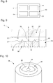
- the method then comprises a second step 22 of pressing the precursor from an upper die and a lower die of a pressing device, shown in FIG. figure 9 , in order to form the green body of the future stone.
- the method includes a third step 23 of sintering the green body to form a body 30 visible on the figure 4 in the material which can be, as we mentioned previously, ceramic.
- this step 23 is intended to sinter the green body in order to form a ceramic body 30 of the future pierced stone.
- the sintering step 23 can include pyrolysis.
- the body 30 comprises a peripheral face 37 and a lower face 32 provided with a groove 40.
- the figure 4 shows the body 30 of the stone after the sintering step, and the final stone 8 in overprinting obtained at the end of the manufacturing process following the various stages of machining of the body.
- the body comprises an upper face 31 and a lower face 32.
- the body 30 further comprises a hole blank 34 provided with the upper and lower parts 35, 36 which are of different shapes. Indeed, the lower part 35, which constitutes the blank of the functional element has a conical shape and the upper part 36 which comprises the blank of the hole 34 has a cylindrical shape.
- Such a hole 34 also comprises a first opening 37 defined in the body 30 and opening into the lower face 32 of this body 30.
- such a blank makes it possible in particular to form the engagement cone 13 of the stone 8 for easier mounting of the pivot, in particular when it comes to mounting it blind in the drilled stone.
- the shape of the through hole 9 is provided by the shape of a punch of the lower die of the pressing device.
- a pressing step 22 of the device of the figure 3 is intended to compress, using the upper matrix and the lower matrix, the precursor in order to form said green body of the future stone 8.
- the body 30 of the figure 4 comprises a groove 40 on its underside 32.
- the groove 40 preferably describes a circular path centered around the hole blank 34.
- the groove 40 preferably has a section of substantially triangular shape. However, other shapes are possible, and may for example be slightly convex or concave. As shown in the figure, the diameter of the circular path of the groove 40 determines the width of the final stone.
- the groove 40 is circular and centered on the underside of the stone.
- the groove has a substantially triangular section.
- the groove comprises an internal face 41 and an external face 42 forming the two ridges of its triangular section, the third ridge 43 being open on the lower face of the body.
- the internal face 41 will form the flared part of the peripheral face, while the external face 42 will be eliminated subsequently.
- the periphery of the final stone is defined by the groove 40.
- the groove 40 is formed by the lower die of the pressing device, shown in the figures. figures 9 and 10 , the lower die comprising a negative shape of the groove 40, such as an annular projecting rib.
- the method 20 comprises a fourth step of machining 24 of the body 30 of the future stone 8 of the figure 4 .
- the fourth step 24 comprises a first sub-step of digging a recess 45 in the upper face 31 of the body 30.
- the recess 45 is preferably substantially hemispherical, as can be seen in the figure. figure 5 .
- an opening 46 is made in the blank of the hole 34 making it possible to connect the cone of the lower part 35 to the recess 45.
- the blank of the hole 34 thus comprises a second opening 46 defined in the body and opening into the upper face 31 of this body 30.
- the machining step 24 also comprises a second turning sub-step for planing the peripheral wall 37 of the body 30.
- material is removed, preferably up to the top 47 of the groove so as to obtain a peripheral wall 15 at least in part flared 16.
- the outer face 41 is eliminated during planing.
- the internal face 42 is kept so as to form the flared part 16 of the peripheral face 15 of the future stone.
- the flared part 16 extends from the lower face 12 of the stone 8.
- Another part 48 of the peripheral wall 15 is substantially straight and connects the flared part 16 of the upper face 31, preferably from the top 47 of the. groove 40. This substantially straight portion 48 was formed during planing of the body 30.
- the dimensions of the lower face 12 of the stone 8 are determined by the groove 40, in particular by the junction 49 of the internal face 42 to the face. lower body 32 30.
- the peripheral face can be completely flared.
- the flared part extends from the lower face of smaller diameter, to the upper face of larger diameter.
- the machining step 24 also comprises a third sub-step of cutting the upper face 31 of the body 30, in order to obtain an upper face 11 giving the stone 8 a predetermined thickness, such as that shown in the figure. figure 7 .
- the thickness of stone 8 is chosen according to the configuration of the bearing block.
- the machining step 24 is preferably carried out using destructive radiation of the laser type in order to obtain very precise engraving.
- this step 24 can be obtained using other types of processes such as, for example, mechanical removal such as mechanical drilling or high pressure water cutting.
- a fifth finishing step 25 makes it possible to give the stone 8 a surface state compatible with its use.
- Such a finishing step 25 can thus comprise a lapping and / or a brushing and / or a polishing allowing the adjustment of the final dimensions and / or the removal of edges and / or the local modification of the roughness.
- a surface state Ra 0.025 ⁇ m.
- Such a finishing step 25 can thus comprise a lapping and / or a brushing and / or a polishing allowing the adjustment of the final dimensions and / or the removal of edges and / or the local modification of the roughness.
- Such a system 50 is capable of implementing a method for manufacturing the stone 8 shown in FIG. figure 2 going through the stages of figures 4 to 7 .
- each die 57, 58 is fixed on a double-acting press.
- a dies 57, 58 (or both) is brought together in directions A in the housing 59 of this pressing device 52 so as to form not only upper and lower faces 31, 32 of a body 30 of the future stone 8, but also the peripheral face 37 of this body 30.
- the dies 57, 58 are substantially plane and the lower die 58 comprises a punch 56 intended to form a blind cavity 34 in the body 30
- This punch 56 comprises a main part having a conical shape and a substantially cylindrical distal part which is provided with a point. The main part and the distal part are intended to form respectively the lower part 35 and the upper part 36 of the blind cavity 34.
- the lower die 58 further comprises a protruding rib 60 configured to form the groove 40 on the underside 32 of the body 30.
- the protruding rib 60 is preferably circular and centered on the lower die 58.
- the protruding rib 60 is preferably circular and centered on the lower die 58.
- protruding rib 60 has dimensions and a shape corresponding to those of the groove 40, since it is this which forms the groove 40 in the underside of the body 30.
- the protruding rib 60 also preferably has a substantially section. triangular.
- the lower die 58 comprises a face 62 delimited by the projecting rib 60 and corresponding to the dimensions of the lower face 12 of the stone 8.
- the lower die 58 provided with the punch 56 and the projecting rib 60, prints the face. lower 32 of the body 30 of its forms. Thanks to this system 50, the desired green body is obtained, which is subsequently sintered to form the body 30, which will lead to stone 8 after machining.
Landscapes
- Engineering & Computer Science (AREA)
- Chemical & Material Sciences (AREA)
- Physics & Mathematics (AREA)
- Manufacturing & Machinery (AREA)
- General Physics & Mathematics (AREA)
- Mechanical Engineering (AREA)
- Ceramic Engineering (AREA)
- Organic Chemistry (AREA)
- Materials Engineering (AREA)
- Structural Engineering (AREA)
- Inorganic Chemistry (AREA)
- General Engineering & Computer Science (AREA)
- Mining & Mineral Resources (AREA)
- Optics & Photonics (AREA)
- Plasma & Fusion (AREA)
- Processing Of Stones Or Stones Resemblance Materials (AREA)
- Press-Shaping Or Shaping Using Conveyers (AREA)
- Adornments (AREA)
- Devices For Post-Treatments, Processing, Supply, Discharge, And Other Processes (AREA)
- Powder Metallurgy (AREA)
Abstract
Description
- L'invention porte sur un procédé de fabrication d'une pierre biseautée, notamment pour un mouvement d'horlogerie.
- L'invention porte aussi sur un système de fabrication permettant la mise en oeuvre du procédé.
- Dans l'état de la technique de l'horlogerie, les pierres de type rubis ou saphir, sont notamment utilisées pour former des contre-pivots ou des éléments de guidage, appelés coussinets, dans des pièces d'horlogerie. Ces contre-pivots et éléments de guidage sont destinés à entrer en contact avec des pivots afin de rendre ces derniers mobiles en rotation et ce, avec un frottement minimal. Ainsi, ils forment, par exemple, tout ou partie d'un palier d'un axe monté en rotation. Les éléments de guidage comprennent généralement un trou traversant pour y insérer l'axe du pivot.
- En principe, on utilise des pierres synthétiques dans les mouvements horlogers. On connait en particulier le procédé de type Verneuil pour fabriquer des pierres de type monocristalline. Il existe aussi les pierres de type poly-cristalline, que l'on fabrique par pressage d'un précurseur en vue de l'obtention d'un corps vert de la future pierre à partir d'un outil de pressage. Les pierres sont ensuite usinées pour obtenir une forme finie aux dimensions désirées.
- En particulier, concernant les éléments de guidage en pierre polycristalline, l'outil de pressage est par exemple pourvu d'un fil participant à l'édification d'une ébauche de trou. Les pierres de type monocristallines sont d'abord percées au laser pour obtenir l'ébauche de trou. La dimension finale du trou est obtenue par la suite grâce à l'usinage.
- Les pierres sont généralement dimensionnées pour être positionnées dans le logement d'un bloc de palier. IL existe notamment les paliers amortisseurs qui permettent d'absorber les chocs.
- La configuration d'un palier amortisseur de choc 1 conventionnel est représentée par la
figure 1 . Une pierre bombée olivée 2 formant un élément de guidage axial pour le pivot, qui est appelée communément coussinet, est chassée dans un support de palier 3 appelé communément chaton, sur lequel est montée une pierre contre-pivot 4. Le chaton 3 est maintenu en appui contre le fond d'un bloc de palier 5 par des moyens élastiques, généralement un ressort amortisseur 6, agencé pour exercer une contrainte axiale sur la partie supérieure de la pierre contre-pivot 4. Un tel palier amortisseur permet d'absorber les chocs selon l'axe longitudinal du pivot, l'ensemble formé du chaton, de la pierre bombée, et de la pierre contre-pivot, pouvant se déplacer grâce au ressort amortisseur 6. - Le chaton 3 comporte en outre une paroi externe évasée agencée en correspondance avec une paroi interne évasée disposée à la périphérie du fond du bloc de palier 5. Il existe également des variantes selon lesquelles le chaton comporte une paroi externe présentant une surface de forme convexe, c'est-à-dire bombée. Ainsi, le palier amortisseur permet d'absorber les chocs radiaux, grâce aux parois évasées du chaton et du fond du bloc de palier 5. En effet, l'ensemble peut se déplacer radialement et axialement de façon simultanée.
- Cependant, on souhaite avoir une pierre unique capable de former à la fois l'élément de guidage et le chaton pour simplifier la disposition des éléments et améliorer la résistance aux chocs. Pour cela, il est nécessaire d'obtenir une pierre avec une paroi périphérique au moins en partie évasée. Or, les procédés actuels d'usinage sont compliqués à mettre en oeuvre pour y arriver.
- Le but de la présente invention est de pallier en tout ou partie les inconvénients cités précédemment en proposant un procédé de fabrication d'une pierre munie d'une face périphérique au moins en partie évasée, afin de pouvoir être insérée dans un bloc de palier amortisseur tel que décrit précédemment Dans ce contexte, un tel procédé de fabrication est répétable et ce, sans engendrer un quelconque endommagement de la pierre ou encore du système de fabrication de cette pierre.
- A cet effet, l'invention porte sur un procédé de fabrication d'une pierre biseautée, notamment pour une pièce d'horlogerie. Le procédé est remarquable en ce qu'il comporte les étapes suivantes :
- réalisation d'un précurseur à partir d'un mélange d'au moins un matériau en poudre avec un liant ;
- pressage du précurseur, à l'aide d'une matrice supérieure et d'une matrice inférieure comprenant une nervure saillante afin de former un corps vert,
- frittage dudit corps vert afin de former un corps de la future pierre dans ledit au moins un matériau, le corps comprenant une face périphérique et une face inférieure munie d'une rainure, et
- usinage du corps comportant une sous-étape de rabotage de la face périphérique jusqu'à la rainure de manière à ce qu'une paroi interne de la rainure forme au moins une partie évasée de la face périphérique de la pierre,
- Ainsi, un tel procédé permet de fabriquer aisément une pierre biseautée munie d'une face périphérique au moins une partie évasée, la pierre étant de préférence de type poly-cristal. Une telle pierre peut ainsi être insérée dans un bloc de palier ayant une forme correspondant à la face évasée, notamment pour absorber les chocs latéraux.
- Selon un mode de réalisation particulier de l'invention, l'usinage comprend une sous-étape de creusement d'une creusure dans la face supérieure du corps.
- Selon un mode de réalisation particulier de l'invention, l'usinage comprend une sous-étape de taille de la face supérieure du corps, afin d'obtenir une face supérieure donnant à la pierre une épaisseur prédéterminée.
- Selon un mode de réalisation particulier de l'invention, le pressage comprend le creusement d'une ébauche de trou au moyen d'un poinçon de la matrice inférieure.
- Selon un mode de réalisation particulier de l'invention, la rainure est réalisée pour être circulaire et/ou centrée sur la face inférieure de la pierre.
- Selon un mode de réalisation particulier de l'invention, la nervure saillante et la rainure ont une section sensiblement triangulaire dont l'un des côtés formera la partie évasée de la face périphérique de la pierre, après le rabotage.
- Selon un mode de réalisation particulier de l'invention, la rainure comprend une face interne et une face externe, la face externe étant éliminée lors du rabotage.
- Selon un mode de réalisation particulier de l'invention, la face interne est conservée lors du rabotage de manière à former la partie évasée de la face périphérique.
- Selon un mode de réalisation particulier de l'invention, l'étape pressage est réalisée par rapprochement des matrices supérieure et inférieure dans un carter.
- Selon un mode de réalisation particulier de l'invention, l'étape frittage comporte une pyrolyse.
- Selon un mode de réalisation particulier de l'invention, le procédé comporte une étape de finition de la pierre, par exemple un rodage et/ou un brossage et/ou un polissage.
- Selon un mode de réalisation particulier de l'invention, le matériau en poudre est à base de céramique et comporte au moins un oxyde métallique, un nitrure métallique ou un carbure métallique.
- Selon un mode de réalisation particulier de l'invention, le matériau en poudre à base de céramique comporte de l'oxyde d'aluminium.
- Selon un mode de réalisation particulier de l'invention, le matériau en poudre à base de céramique comporte en outre de l'oxyde de chrome.
- L'invention porte aussi sur un système de fabrication d'une pierre mettant en oeuvre le procédé selon l'invention. Le système est remarquable en en ce qu'il comprend :
- un dispositif de réalisation d'un précurseur à partir d'un mélange d'au moins un matériau en poudre avec un liant ;
- un dispositif de pressage du précurseur comprenant des matrices supérieure et inférieure agencées mobile dans un carter contribuant à former un corps vert de la future pierre, la matrice inférieure comprenant une nervure saillante ;
- un dispositif de frittage dudit corps vert ; et
- un dispositif d'usinage d'un corps de la future pierre.
- Selon un mode de réalisation particulier de l'invention, la nervure saillante est sensiblement circulaire et/ou centrée sur la matrice inférieure.
- Selon un mode de réalisation particulier de l'invention, la nervure saillante a une section sensiblement triangulaire.
- D'autres particularités et avantages ressortiront clairement de la description qui en est faite ci-après, à titre indicatif et nullement limitatif, en référence aux dessins annexés, dans lesquels :
- la
figure 1 représente schématiquement une section transversale d'un palier amortisseur de choc selon un mode de réalisation connu de l'état de la technique ; - la
figure 2 est une représentation d'une pierre obtenue avec le procédé selon l'invention ; - la
figure 3 un logigramme relatif au procédé de fabrication d'une pierre selon l'invention ; - la
figure 4 est une représentation schématique d'une partie du corps vert obtenue après l'étape de pressage du procédé selon l'invention ; - la
figure 5 est une représentation schématique d'une partie de la pierre après une première sous-étape d'usinage du procédé selon l'invention ; - la
figure 6 est une représentation schématique d'une partie de la pierre après une deuxième sous-étape d'usinage du procédé selon l'invention; - la
figure 7 est une représentation schématique d'une partie de la pierre après une troisième sous-étape d'usinage du procédé selon l'invention ; - la
figure 8 est une représentation schématique d'un système de fabrication d'une pierre selon de l'invention ; - la
figure 9 est une vue schématique d'un dispositif de pressage du système selon l'invention ; et - la
figure 10 est une vue schématique d'une matrice inférieure du dispositif de pressage du système selon l'invention. - Comme expliqué ci-dessus, l'invention se rapporte à un procédé de fabrication d'une pierre susceptible de former un élément de guidage d'une pièce d'horlogerie. La pierre est par exemple destinée à entrer en contact avec un pivot afin de rendre ce dernier mobile en rotation avec un frottement minimal. On comprend donc que la présente invention permet notamment de réaliser une pierre pouvant former tout ou partie d'un palier d'un axe monté en rotation.
- La
figure 2 est un exemple de pierre biseautée 8 obtenue grâce au procédé selon l'invention. Avantageusement, la pierre 8 est traversée par un trou 9 destiné à recevoir un pivot, également appelé tourillon. La pierre 8 comporte, une face supérieure 11 et une face inférieure 12 dont l'une comprend un élément fonctionnel, ici un cône 13, communiquant avec le trou traversant 9. Autrement dit, le trou 9 communique avec la face supérieure 6 et avec aussi un évidement sensiblement conique défini dans la face inférieure 9. Cet évidement forme alors un cône 13 d'engagement de la pierre percée 8. - Dans la description, on parle de face supérieure et de face inférieure par rapport aux figures, notamment pour les distinguer. Néanmoins, les faces supérieure et inférieure peuvent être inversées.
- On remarque également qu'une paroi interne du corps de cette pierre définie au niveau du trou 19 comporte une zone arrondie 14 destinée à minimiser le contact avec le pivot mais également à faciliter une éventuelle lubrification. On notera que la minimisation du contact avec le pivot permet notamment de diminuer les frottements avec le pivot.
- La pierre biseautée 8 a en outre une face périphérique 15 en partie évasée, et reliant la face inférieure 12 de plus petite surface à la face supérieure 11 de plus grande surface. La partie évasée 16 est destinée à être en contact avec une paroi interne d'un bloc de palier de manière à absorber les chocs latéraux, la pierre pouvant glisser sur la paroi du bloc grâce à la paroi évasée, comme dans l'exemple de la
figure 1 . - La pierre 8 est, de préférence, formée à partir d'un corps minéral de type polycristallin, le corps comprenant par exemple du polyrubis de type al2O3Cr ou de la Zircone de type ZrO2.
- Le procédé de fabrication 20 d'une telle pierre, qui est représenté sur la
figure 3 , comporte six étapes. - Une première étape 21 consiste à réaliser un précurseur à partir d'un mélange d'au moins un matériau en poudre avec un liant. Ce matériau peut être de manière non limitative et non exhaustive de la céramique. Cette étape est destinée à former un précurseur à partir d'une poudre à base de céramique prise dans le liant.
- Dans ce contexte, la poudre à base de céramique peut comporter au moins un oxyde métallique, un nitrure métallique ou un carbure métallique. A titre d'exemple, la poudre à base de céramique peut comporter de l'oxyde d'aluminium afin de former du saphir synthétique ou un mélange d'oxyde d'aluminium et d'oxyde de chrome afin de former du rubis synthétique, ou encore de l'oxyde de zirconium. De plus, le liant peut être de natures variées comme, par exemple, de types polymères ou de types organiques.
- Le procédé comporte ensuite une deuxième étape de pressage 22 du précurseur à partir d'une matrice supérieure et d'une matrice inférieure d'un dispositif de pressage, représenté sur la
figure 9 , afin de former le corps vert de la future pierre. - Le procédé comporte une troisième étape 23 de frittage du corps vert afin de former un corps 30 visible sur la
figure 4 dans le matériau qui peut être ainsi que nous l'avons évoqué précédemment, de la céramique. Autrement dit, cette étape 23 est destinée à fritter le corps vert afin de former un corps 30 en céramique de la future pierre percée. Préférentiellement selon l'invention, l'étape de frittage 23 peut comporter une pyrolyse. - Selon l'invention, le corps 30 comprend une face périphérique 37 et une face inférieure 32 munie d'une rainure 40. La
figure 4 montre le corps 30 de la pierre après l'étape de frittage, et la pierre finale 8 en surimpression obtenue à la fin du procédé de fabrication suite aux différentes étapes d'usinage du corps. Le corps comprend une face supérieure 31 et une face inférieure 32. Le corps 30 comprend de plus une ébauche de trou 34 pourvue des parties supérieure et inférieure 35, 36 qui sont de formes différentes. En effet, la partie inférieure 35, qui constitue l'ébauche de l'élément fonctionnel a une forme conique et la partie supérieure 36 qui comprend l'ébauche du trou 34 a une forme cylindrique. Un tel trou 34 comprend aussi une première ouverture 37 définie dans le corps 30 et débouchant dans la face inférieure 32 de ce corps 30. - On notera qu'une telle ébauche permet notamment de former le cône d'engagement 13 de la pierre 8 pour un montage plus aisé du pivot notamment lorsqu'il s'agit de le monter à l'aveugle dans la pierre percée formant dans cet exemple un élément de guidage. On comprend donc que la forme du trou traversant 9 est apportée par la forme d'un poinçon de la matrice inférieure du dispositif de pressage. Ainsi, une telle étape de pressage 22 du dispositif de la
figure 3 , est destinée à compresser, à l'aide de la matrice supérieure et la matrice inférieure, le précurseur afin de former ledit corps vert de la future pierre 8. - Selon l'invention, le corps 30 de la
figure 4 comprend une rainure 40 sur sa face inférieure 32. La rainure 40 décrit, de préférence, un chemin circulaire centré autour de l'ébauche de trou 34. La rainure 40 a, de préférence, une section de forme sensiblement triangulaire. Néanmoins, d'autres formes sont possibles, et peuvent par exemple être légèrement convexes ou concaves. Comme le montre la figure, le diamètre du chemin circulaire de la rainure 40 détermine la largeur de la pierre finale. - La rainure 40 est circulaire et centrée sur la face inférieure de la pierre. La rainure a une section sensiblement triangulaire. La rainure comprend une face interne 41 et une face externe 42 formant les deux arêtes de sa section triangulaire, la troisième arête 43 étant ouverte sur la face inférieure du corps. La face interne 41 formera la partie évasée de la face périphérique, tandis que la face externe 42 sera éliminée par la suite. La périphérie de la pierre finale est définie par la rainure 40. La rainure 40 est formée par la matrice inférieure du dispositif de pressage, représenté sur les
figures 9 et 10 , la matrice inférieure comportant une forme en négatif de la rainure 40, telle une nervure saillante annulaire. - Sur la
figure 3 , le procédé 20 comprend une quatrième étape d'usinage 24 du corps 30 de la future pierre 8 de lafigure 4 . La quatrième étape 24 comporte une première sous-étape de creusement d'une creusure 45 dans la face supérieure 31 du corps 30. La creusure 45 est, de préférence, sensiblement hémisphérique, comme on peut le voir sur lafigure 5 . Lors du déroulement de cette sous étape, une ouverture 46 est réalisée dans l'ébauche du trou 34 permettant de relier le cône de la partie inférieure 35 à la creusure 45. L'ébauche du trou 34 comprend ainsi une seconde ouverture 46 définie dans le corps et débouchant dans la face supérieure 31 de ce corps 30. - L'étape d'usinage 24 comprend aussi une deuxième sous-étape de tournage pour raboter la paroi périphérique 37 du corps 30. Comme le montre la
figure 6 , on enlève de la matière, de préférence jusqu'au sommet 47 de la rainure de manière à obtenir une paroi périphérique 15 au moins en partie évasée 16. Ainsi, la face externe 41 est éliminée lors du rabotage. En revanche, la face interne 42 est conservée de manière à former la partie évasée 16 de la face périphérique 15 de la future pierre. La partie évasée 16 s'étend depuis la face inférieure 12 de la pierre 8. Une autre partie 48 de la paroi périphérique 15 est sensiblement droite et relie la partie évasée 16 de à la face supérieure 31, de préférence depuis le sommet 47 de la rainure 40. Cette partie 48 sensiblement droite a été formée lors du rabotage du corps 30. Les dimensions de la face inférieure 12 de la pierre 8 sont déterminées par la rainure 40, en particulier par la jonction 49 de la face interne 42 à la face inférieure 32 du corps 30. - Selon une variante non représentée, la face périphérique peut être entièrement évasée. Dans ce cas, la partie évasée s'étend depuis la face inférieure de plus petit diamètre, jusqu'à la face supérieure de plus grand diamètre.
- L'étape d'usinage 24 comprend encore une troisième sous étape de taille de la face supérieure 31 du corps 30, afin d'obtenir une face supérieure 11 donnant à la pierre 8 une épaisseur prédéterminée, telle que celle représentée sur la
figure 7 . On choisit l'épaisseur de la pierre 8 en fonction de la configuration du bloc de palier. - L'étape d'usinage 24 est préférentiellement réalisée à l'aide d'un rayonnement destructif du type laser afin d'obtenir une gravure très précise. Toutefois, cette étape 24 peut être obtenue à l'aide d'autres types de processus comme, par exemple, un retrait mécanique tel qu'un perçage mécanique ou une découpe à eau haute pression.
- Enfin, une cinquième étape 25 de finition permet de donner à la pierre 8 un état de surface compatible avec son utilisation. Une telle étape de finition 25 peut ainsi comporter un rodage et/ou un brossage et/ou un polissage permettant l'ajustage des cotes finales et/ou le retrait d'arêtes et/ou la modification locale de la rugosité. On cherche par exemple à obtenir un état de surface Ra=0.025µm. Une telle étape de finition 25 peut ainsi comporter un rodage et/ou un brossage et/ou un polissage permettant l'ajustage des cotes finales et/ou le retrait d'arêtes et/ou la modification locale de la rugosité.
- En référence à la
figure 8 , l'invention porte aussi sur un système de fabrication 50 de la pierre. Ce système 50 comprend les différents dispositifs suivants : - un dispositif de réalisation 51 d'un précurseur à partir d'un mélange d'au moins un matériau en poudre avec un liant ;
- un dispositif de pressage 52 du matériau précurseur comprenant des matrices supérieure et inférieure 57, 58 agencées mobiles dans un carter 59 contribuant à former un corps vert de la future pierre 8 ;
- un dispositif de frittage 53 dudit corps vert, et
- un dispositif d'usinage 54 du corps 30 de la future pierre 8 issu du frittage du corps vert.
- On notera qu'au moins deux de ces dispositifs 51 à 54 peuvent former ensemble une même entité du système 50. Un tel système 50 est apte à mettre en oeuvre un procédé de fabrication de la pierre 8 représentée sur la
figure 2 en passant par les étapes desfigures 4 à 7 . - Dans le dispositif de pressage 52 visible sur les
figures 9 et 10 , chaque matrice 57, 58 est fixée sur une presse double effet. Selon l'invention, une des matrices 57, 58 (ou les deux) est rapprochée de l'autre selon les directions A dans le carter 59 de ce dispositif de pressage 52 afin de former non seulement des faces supérieure et inférieure 31, 32 d'un corps 30 de la future pierre 8, mais également la face périphérique 37 de ce corps 30. Dans ce dispositif de pressage 52, les matrices 57, 58 sont sensiblement planes et la matrice inférieure 58 comporte un poinçon 56 destiné à former une cavité borgne 34 dans le corps 30. Ce poinçon 56 comprend une partie principale ayant une forme conique et une partie distale essentiellement cylindrique qui est pourvue d'une pointe. La partie principale et la partie distale sont destinées à former respectivement la partie inférieure 35 et la partie supérieure 36 de la cavité borgne 34. - Selon l'invention, la matrice inférieure 58 comporte en outre une nervure saillante 60 configurée pour former la rainure 40 sur la face inférieure 32 du corps 30. La nervure saillante 60 est, de préférence, circulaire et centrée sur la matrice inférieure 58. La nervure saillante 60 a des dimensions et une forme correspondant à celles de la rainure 40, car c'est elle qui forme la rainure 40 dans la face inférieure du corps 30. Ainsi, la nervure saillante 60 a également, de préférence, une section sensiblement triangulaire. La matrice inférieure 58 comprend une face 62 délimitée par la nervure saillante 60 et correspondant aux dimensions de la face inférieure 12 de la pierre 8. Lors du pressage, la matrice inférieure 58 munie du poinçon 56 et de la nervure saillante 60, imprime la face inférieure 32 du corps 30 de ses formes. Grâce à ce système 50, on obtient le corps vert souhaité, qui est fritté par la suite pour former le corps 30, qui permettra d'aboutir à la pierre 8 après usinage.
- Bien entendu, la présente invention ne se limite pas à l'exemple illustré mais est susceptible de diverses variantes et modifications qui apparaîtront à l'homme de l'art. En particulier, d'autres types d'éléments fonctionnels formés par d'autres géométries de nervures saillantes et/ou de matrices 57, 58 peuvent être envisagés avantageusement selon l'invention.
Claims (17)
- Procédé de fabrication (20) d'une pierre biseautée (8), notamment pour une pièce d'horlogerie, caractérisé en ce qu'il comporte les étapes suivantes :- réalisation (21) d'un précurseur à partir d'un mélange d'au moins un matériau en poudre avec un liant ;- pressage (22) du précurseur afin de former un corps vert, à l'aide d'une matrice supérieure (57) et d'une matrice inférieure (58) comprenant une nervure saillante (60),- frittage (23) dudit corps vert afin de former un corps (30) de la future pierre (8) dans ledit au moins un matériau, le corps (30) comprenant une face périphérique (37) et une face inférieure (32) munie d'une rainure (40), et- usinage (24) du corps (30) comportant une sous-étape de rabotage de la face périphérique (37) jusqu'à la rainure (40), de manière à ce qu'une paroi interne (42) de la rainure forme au moins une partie évasée (16) de la face périphérique (15) de la pierre (8).
- Procédé selon la revendication précédente, caractérisé en ce que l'usinage (24) comprend une sous-étape de creusement d'une creusure (45) dans la face supérieure (31) du corps (30).
- Procédé selon l'une, quelconque, des revendications précédentes, caractérisé en ce que l'usinage comprend une sous-étape de taille de la face supérieure (31) du corps (30), afin d'obtenir une face supérieure (11) donnant à la pierre (8) une épaisseur prédéterminée.
- Procédé selon l'une, quelconque, des revendications précédentes, caractérisé en ce que le pressage (22) comprend le creusement d'une ébauche (34) de trou au moyen d'un poinçon (56) de la matrice inférieure (58).
- Procédé selon l'une, quelconque, des revendications précédentes, caractérisé en ce que la rainure (40) est réalisée de manière être circulaire et/ou centrée sur la face inférieure (32) du corps (30).
- Procédé selon l'une, quelconque, des revendications précédentes, caractérisé en ce que la nervure saillante (60) et la rainure (40) ont une section sensiblement triangulaire dont l'un des côtés formera la partie évasée (16) de la face périphérique (15) de la pierre (8), après le rabotage.
- Procédé selon l'une, quelconque, des revendications précédentes, caractérisé en ce que la rainure (40) comprend une face interne (42) et une face externe (41), la face externe (41) étant éliminée lors du rabotage.
- Procédé selon la revendication précédente, caractérisé en ce que la face interne (42) est conservée lors du rabotage de manière à former la partie évasée (16) de la face périphérique (15).
- Procédé selon l'une des revendications précédentes, caractérisé en ce que l'étape pressage (22) est réalisée par rapprochement des matrices supérieure et inférieure (57, 58) dans un carter (59).
- Procédé selon l'une des revendications précédentes, caractérisé en ce que l'étape de frittage (23) comporte une pyrolyse.
- Procédé selon l'une des revendications précédentes, caractérisé en ce qu'il comporte une étape de finition (25) de la pierre (8), par exemple un rodage et/ou un brossage et/ou un polissage.
- Procédé selon l'une des revendications précédentes, caractérisé en ce que le matériau en poudre est à base de céramique et comporte au moins un oxyde métallique, un nitrure métallique ou un carbure métallique.
- Procédé selon la revendication précédente, caractérisé en ce que le matériau en poudre à base de céramique comporte de l'oxyde d'aluminium.
- Procédé selon la revendication précédente, caractérisé en ce que le matériau en poudre à base de céramique comporte en outre de l'oxyde de chrome.
- Système de fabrication (50) d'une pierre (8) mettant en oeuvre le procédé selon l'une des revendications 1 à 14, caractérisé en ce qu'il comprend :- un dispositif de réalisation (51) d'un précurseur à partir d'un mélange d'au moins un matériau en poudre avec un liant ;- un dispositif de pressage (52) du précurseur comprenant des matrices supérieure et inférieure (57, 58) agencées mobile dans un carter (59) contribuant à former un corps vert de la future pierre (8), la matrice inférieure (58) comprenant une nervure saillante (60) ;- un dispositif de frittage (53) dudit corps vert ; et- un dispositif d'usinage (54) d'un corps (30) de la future pierre (8).
- Système selon la revendication précédente, caractérisé en ce que la nervure saillante (60) est sensiblement circulaire et/ou centrée sur la matrice inférieure (58).
- Système selon la revendication 15 ou 16, caractérisé en ce que la nervure saillante (60) a une section sensiblement triangulaire.
Priority Applications (8)
| Application Number | Priority Date | Filing Date | Title |
|---|---|---|---|
| EP19188535.9A EP3770697B1 (fr) | 2019-07-26 | 2019-07-26 | Procede de fabrication d'une pierre biseautee, notamment pour un mouvement d'horlogerie |
| US16/893,590 US11703806B2 (en) | 2019-07-26 | 2020-06-05 | Method for manufacturing a bevelled stone, particularly for a horological movement |
| JP2020108539A JP2021021723A (ja) | 2019-07-26 | 2020-06-24 | とりわけ時計学的ムーブメントのための傾斜石を製造するための方法 |
| KR1020200088425A KR102798867B1 (ko) | 2019-07-26 | 2020-07-16 | 특히 시측 무브먼트용의 베벨형 스톤을 제조하기 위한 방법 |
| CN202010722920.XA CN112297190A (zh) | 2019-07-26 | 2020-07-24 | 用于制造尤其用于钟表机芯的倒角宝石的方法 |
| CN202411615936.5A CN119238755A (zh) | 2019-07-26 | 2020-07-24 | 用于制造尤其用于钟表机芯的倒角宝石的方法 |
| JP2022096283A JP7397915B2 (ja) | 2019-07-26 | 2022-06-15 | とりわけ時計学的ムーブメントのための傾斜石を製造するための方法 |
| US17/873,777 US20220365487A1 (en) | 2019-07-26 | 2022-07-26 | Method for manufacturing a bevelled stone, particularly for a horological movement |
Applications Claiming Priority (1)
| Application Number | Priority Date | Filing Date | Title |
|---|---|---|---|
| EP19188535.9A EP3770697B1 (fr) | 2019-07-26 | 2019-07-26 | Procede de fabrication d'une pierre biseautee, notamment pour un mouvement d'horlogerie |
Publications (2)
| Publication Number | Publication Date |
|---|---|
| EP3770697A1 true EP3770697A1 (fr) | 2021-01-27 |
| EP3770697B1 EP3770697B1 (fr) | 2023-08-30 |
Family
ID=67439040
Family Applications (1)
| Application Number | Title | Priority Date | Filing Date |
|---|---|---|---|
| EP19188535.9A Active EP3770697B1 (fr) | 2019-07-26 | 2019-07-26 | Procede de fabrication d'une pierre biseautee, notamment pour un mouvement d'horlogerie |
Country Status (5)
| Country | Link |
|---|---|
| US (2) | US11703806B2 (fr) |
| EP (1) | EP3770697B1 (fr) |
| JP (2) | JP2021021723A (fr) |
| KR (1) | KR102798867B1 (fr) |
| CN (2) | CN112297190A (fr) |
Cited By (3)
| Publication number | Priority date | Publication date | Assignee | Title |
|---|---|---|---|---|
| CN113977741A (zh) * | 2021-11-10 | 2022-01-28 | 浙江骏海新材料有限公司 | 一种高耐磨硅莫砖的加工方法及装置 |
| CN115625343A (zh) * | 2022-09-30 | 2023-01-20 | 成都飞机工业(集团)有限责任公司 | 一种连接区域成形方法 |
| EP4018268B1 (fr) * | 2019-08-19 | 2024-09-04 | Rolex Sa | Procédé de fabrication d'un palier horloger |
Families Citing this family (1)
| Publication number | Priority date | Publication date | Assignee | Title |
|---|---|---|---|---|
| EP3835882B1 (fr) * | 2019-12-10 | 2025-11-05 | Comadur S.A. | Pierre, notamment pour un mouvement d'horlogerie, et son procédé de fabrication |
Citations (3)
| Publication number | Priority date | Publication date | Assignee | Title |
|---|---|---|---|---|
| JP2003080514A (ja) * | 2001-09-07 | 2003-03-19 | Noritake Co Ltd | プレス金型およびセラミック基板製造方法 |
| EP2778801A1 (fr) * | 2013-03-11 | 2014-09-17 | Comadur S.A. | Coussinet comportant des premier et deuxième éléments fonctionnels sur deux faces distinctes |
| EP3483665A1 (fr) * | 2017-11-13 | 2019-05-15 | Comadur S.A. | Procede de fabrication d'une pierre percee |
Family Cites Families (18)
| Publication number | Priority date | Publication date | Assignee | Title |
|---|---|---|---|---|
| CH156949A (fr) | 1927-11-19 | 1932-08-31 | Tavannes Watch Co Sa | Palier pour mouvements d'horlogerie. |
| CH216723A (fr) | 1940-10-03 | 1941-09-15 | Rolex Montres | Coussinet pour axe de mobile de pièce d'horlogerie et procédé pour sa fabrication. |
| CH244264A (fr) | 1944-04-21 | 1946-08-31 | Morf Ernest | Palier pare-chocs pour pièce d'horlogerie. |
| JPS502846Y1 (fr) * | 1970-02-04 | 1975-01-25 | ||
| JPS4830445A (fr) * | 1971-08-24 | 1973-04-21 | ||
| JPS5931104B2 (ja) * | 1979-12-10 | 1984-07-31 | 三菱電機株式会社 | 印鑑照合装置 |
| JP2001319967A (ja) * | 2000-05-11 | 2001-11-16 | Ibiden Co Ltd | セラミック基板の製造方法 |
| US20020135108A1 (en) * | 2001-03-23 | 2002-09-26 | Billiet Romain L. | Polycrystalline watch jewels and method of fabrication thereof |
| JP4539031B2 (ja) * | 2002-05-28 | 2010-09-08 | パナソニック電工株式会社 | 光電気混載基板の製造方法 |
| US20030222025A1 (en) * | 2002-06-04 | 2003-12-04 | Archuleta John Paul | Use of foamed glass article for environment remediation and filtration |
| JP5010377B2 (ja) | 2007-07-20 | 2012-08-29 | 株式会社東芝 | 回折光学素子、回折光学素子成形用金型、および回折光学素子成形用金型の製造方法 |
| WO2010102645A1 (fr) * | 2009-03-11 | 2010-09-16 | Avure Technologies Ab | Récipient sous pression pour presse haute pression |
| JP2011180006A (ja) | 2010-03-02 | 2011-09-15 | Seiko Instruments Inc | 時計用軸受ユニット、ムーブメントおよび携帯用時計 |
| US20130049575A1 (en) * | 2010-07-14 | 2013-02-28 | Shunsuke Fujita | Phosphor composite member, led device and method for manufacturing phosphor composite member |
| CH707740B1 (fr) | 2013-03-11 | 2021-05-31 | Comadur Sa | Coussinet comportant des premier et deuxième éléments fonctionnels sur deux faces distinctes et son procédé de fabrication. |
| EP2969394B1 (fr) * | 2013-03-12 | 2020-08-05 | 3M Innovative Properties Company | Article abrasif agglomere |
| JP2017058248A (ja) * | 2015-09-16 | 2017-03-23 | セイコーインスツル株式会社 | 押え部材、耐振軸受、ムーブメントおよび時計 |
| EP3470936B1 (fr) | 2017-10-16 | 2020-06-03 | The Swatch Group Research and Development Ltd | Procédé de découpe de glace d'horlogerie |
-
2019
- 2019-07-26 EP EP19188535.9A patent/EP3770697B1/fr active Active
-
2020
- 2020-06-05 US US16/893,590 patent/US11703806B2/en active Active
- 2020-06-24 JP JP2020108539A patent/JP2021021723A/ja active Pending
- 2020-07-16 KR KR1020200088425A patent/KR102798867B1/ko active Active
- 2020-07-24 CN CN202010722920.XA patent/CN112297190A/zh active Pending
- 2020-07-24 CN CN202411615936.5A patent/CN119238755A/zh active Pending
-
2022
- 2022-06-15 JP JP2022096283A patent/JP7397915B2/ja active Active
- 2022-07-26 US US17/873,777 patent/US20220365487A1/en active Pending
Patent Citations (3)
| Publication number | Priority date | Publication date | Assignee | Title |
|---|---|---|---|---|
| JP2003080514A (ja) * | 2001-09-07 | 2003-03-19 | Noritake Co Ltd | プレス金型およびセラミック基板製造方法 |
| EP2778801A1 (fr) * | 2013-03-11 | 2014-09-17 | Comadur S.A. | Coussinet comportant des premier et deuxième éléments fonctionnels sur deux faces distinctes |
| EP3483665A1 (fr) * | 2017-11-13 | 2019-05-15 | Comadur S.A. | Procede de fabrication d'une pierre percee |
Cited By (3)
| Publication number | Priority date | Publication date | Assignee | Title |
|---|---|---|---|---|
| EP4018268B1 (fr) * | 2019-08-19 | 2024-09-04 | Rolex Sa | Procédé de fabrication d'un palier horloger |
| CN113977741A (zh) * | 2021-11-10 | 2022-01-28 | 浙江骏海新材料有限公司 | 一种高耐磨硅莫砖的加工方法及装置 |
| CN115625343A (zh) * | 2022-09-30 | 2023-01-20 | 成都飞机工业(集团)有限责任公司 | 一种连接区域成形方法 |
Also Published As
| Publication number | Publication date |
|---|---|
| JP7397915B2 (ja) | 2023-12-13 |
| JP2022120139A (ja) | 2022-08-17 |
| EP3770697B1 (fr) | 2023-08-30 |
| KR102798867B1 (ko) | 2025-04-21 |
| CN119238755A (zh) | 2025-01-03 |
| CN112297190A (zh) | 2021-02-02 |
| US11703806B2 (en) | 2023-07-18 |
| US20220365487A1 (en) | 2022-11-17 |
| US20210026307A1 (en) | 2021-01-28 |
| JP2021021723A (ja) | 2021-02-18 |
| KR20210013530A (ko) | 2021-02-04 |
Similar Documents
| Publication | Publication Date | Title |
|---|---|---|
| EP2778801B1 (fr) | Coussinet comportant des premier et deuxième éléments fonctionnels sur deux faces distinctes | |
| EP3770697B1 (fr) | Procede de fabrication d'une pierre biseautee, notamment pour un mouvement d'horlogerie | |
| EP3483665B1 (fr) | Procede de fabrication d'une pierre percee | |
| EP3835882B1 (fr) | Pierre, notamment pour un mouvement d'horlogerie, et son procédé de fabrication | |
| EP3835881B1 (fr) | Pierre, notamment pour un mouvement d'horlogerie, et son procédé de fabrication | |
| EP2656151B1 (fr) | Assemblage d'une pièce ne comportant pas de domaine plastique | |
| EP4018268B1 (fr) | Procédé de fabrication d'un palier horloger | |
| EP3770698B1 (fr) | Pierre minérale de type monocristalline munie d'un cone de recentrage d'un pivot, et son procédé de fabrication | |
| EP4004653B1 (fr) | Pierre, notamment pour un mouvement d'horlogerie, et son procede de fabrication | |
| EP3367182A1 (fr) | Palier support d'axe a frottement réduit | |
| EP3519902B1 (fr) | Palier support d'axe a frottement reduit | |
| CH716925A2 (fr) | Pierre, notamment pour un mouvement d'horlogerie, et son procédé de fabrication. | |
| CH716431A2 (fr) | Pierre, notamment pour un mouvement d'horlogerie, et son procédé de fabrication. | |
| CH716429A2 (fr) | Procédé de fabrication d'une pierre biseautée, notamment pour un mouvement d'horlogerie. | |
| CH716924A2 (fr) | Pierre, notamment pour un mouvement d'horlogerie, et son procédé de fabrication. | |
| CH707740B1 (fr) | Coussinet comportant des premier et deuxième éléments fonctionnels sur deux faces distinctes et son procédé de fabrication. | |
| CH716430A2 (fr) | Pierre minérale de type monocristalline munie d'un cone de recentrage d'un pivot, et son procédé de fabrication. | |
| CH716178B1 (fr) | Procédé de fabrication d'un palier horloger. | |
| HK40073150B (zh) | 尤其用於时计机芯的石材及其制造方法 | |
| CH712587B1 (fr) | Palier support d'axe à frottement réduit. | |
| EP1465781B1 (fr) | Outillage pour la fabrication de pointes de stylos-billes | |
| HK40045861A (en) | Method for manufacturing a bevelled stone, particularly for a horological movement | |
| EP3974913A1 (fr) | Barillet pour pièce d'horlogerie |
Legal Events
| Date | Code | Title | Description |
|---|---|---|---|
| PUAI | Public reference made under article 153(3) epc to a published international application that has entered the european phase |
Free format text: ORIGINAL CODE: 0009012 |
|
| STAA | Information on the status of an ep patent application or granted ep patent |
Free format text: STATUS: THE APPLICATION HAS BEEN PUBLISHED |
|
| AK | Designated contracting states |
Kind code of ref document: A1 Designated state(s): AL AT BE BG CH CY CZ DE DK EE ES FI FR GB GR HR HU IE IS IT LI LT LU LV MC MK MT NL NO PL PT RO RS SE SI SK SM TR |
|
| AX | Request for extension of the european patent |
Extension state: BA ME |
|
| STAA | Information on the status of an ep patent application or granted ep patent |
Free format text: STATUS: REQUEST FOR EXAMINATION WAS MADE |
|
| 17P | Request for examination filed |
Effective date: 20210727 |
|
| RBV | Designated contracting states (corrected) |
Designated state(s): AL AT BE BG CH CY CZ DE DK EE ES FI FR GB GR HR HU IE IS IT LI LT LU LV MC MK MT NL NO PL PT RO RS SE SI SK SM TR |
|
| GRAP | Despatch of communication of intention to grant a patent |
Free format text: ORIGINAL CODE: EPIDOSNIGR1 |
|
| STAA | Information on the status of an ep patent application or granted ep patent |
Free format text: STATUS: GRANT OF PATENT IS INTENDED |
|
| INTG | Intention to grant announced |
Effective date: 20230420 |
|
| GRAS | Grant fee paid |
Free format text: ORIGINAL CODE: EPIDOSNIGR3 |
|
| P01 | Opt-out of the competence of the unified patent court (upc) registered |
Effective date: 20230611 |
|
| GRAA | (expected) grant |
Free format text: ORIGINAL CODE: 0009210 |
|
| STAA | Information on the status of an ep patent application or granted ep patent |
Free format text: STATUS: THE PATENT HAS BEEN GRANTED |
|
| AK | Designated contracting states |
Kind code of ref document: B1 Designated state(s): AL AT BE BG CH CY CZ DE DK EE ES FI FR GB GR HR HU IE IS IT LI LT LU LV MC MK MT NL NO PL PT RO RS SE SI SK SM TR |
|
| REG | Reference to a national code |
Ref country code: GB Ref legal event code: FG4D Free format text: NOT ENGLISH |
|
| REG | Reference to a national code |
Ref country code: CH Ref legal event code: EP |
|
| REG | Reference to a national code |
Ref country code: DE Ref legal event code: R096 Ref document number: 602019035986 Country of ref document: DE |
|
| REG | Reference to a national code |
Ref country code: IE Ref legal event code: FG4D Free format text: LANGUAGE OF EP DOCUMENT: FRENCH |
|
| REG | Reference to a national code |
Ref country code: LT Ref legal event code: MG9D |
|
| REG | Reference to a national code |
Ref country code: NL Ref legal event code: MP Effective date: 20230830 |
|
| REG | Reference to a national code |
Ref country code: AT Ref legal event code: MK05 Ref document number: 1606222 Country of ref document: AT Kind code of ref document: T Effective date: 20230830 |
|
| PG25 | Lapsed in a contracting state [announced via postgrant information from national office to epo] |
Ref country code: GR Free format text: LAPSE BECAUSE OF FAILURE TO SUBMIT A TRANSLATION OF THE DESCRIPTION OR TO PAY THE FEE WITHIN THE PRESCRIBED TIME-LIMIT Effective date: 20231201 |
|
| PG25 | Lapsed in a contracting state [announced via postgrant information from national office to epo] |
Ref country code: IS Free format text: LAPSE BECAUSE OF FAILURE TO SUBMIT A TRANSLATION OF THE DESCRIPTION OR TO PAY THE FEE WITHIN THE PRESCRIBED TIME-LIMIT Effective date: 20231230 |
|
| PG25 | Lapsed in a contracting state [announced via postgrant information from national office to epo] |
Ref country code: SE Free format text: LAPSE BECAUSE OF FAILURE TO SUBMIT A TRANSLATION OF THE DESCRIPTION OR TO PAY THE FEE WITHIN THE PRESCRIBED TIME-LIMIT Effective date: 20230830 Ref country code: RS Free format text: LAPSE BECAUSE OF FAILURE TO SUBMIT A TRANSLATION OF THE DESCRIPTION OR TO PAY THE FEE WITHIN THE PRESCRIBED TIME-LIMIT Effective date: 20230830 Ref country code: NO Free format text: LAPSE BECAUSE OF FAILURE TO SUBMIT A TRANSLATION OF THE DESCRIPTION OR TO PAY THE FEE WITHIN THE PRESCRIBED TIME-LIMIT Effective date: 20231130 Ref country code: LV Free format text: LAPSE BECAUSE OF FAILURE TO SUBMIT A TRANSLATION OF THE DESCRIPTION OR TO PAY THE FEE WITHIN THE PRESCRIBED TIME-LIMIT Effective date: 20230830 Ref country code: LT Free format text: LAPSE BECAUSE OF FAILURE TO SUBMIT A TRANSLATION OF THE DESCRIPTION OR TO PAY THE FEE WITHIN THE PRESCRIBED TIME-LIMIT Effective date: 20230830 Ref country code: IS Free format text: LAPSE BECAUSE OF FAILURE TO SUBMIT A TRANSLATION OF THE DESCRIPTION OR TO PAY THE FEE WITHIN THE PRESCRIBED TIME-LIMIT Effective date: 20231230 Ref country code: HR Free format text: LAPSE BECAUSE OF FAILURE TO SUBMIT A TRANSLATION OF THE DESCRIPTION OR TO PAY THE FEE WITHIN THE PRESCRIBED TIME-LIMIT Effective date: 20230830 Ref country code: GR Free format text: LAPSE BECAUSE OF FAILURE TO SUBMIT A TRANSLATION OF THE DESCRIPTION OR TO PAY THE FEE WITHIN THE PRESCRIBED TIME-LIMIT Effective date: 20231201 Ref country code: FI Free format text: LAPSE BECAUSE OF FAILURE TO SUBMIT A TRANSLATION OF THE DESCRIPTION OR TO PAY THE FEE WITHIN THE PRESCRIBED TIME-LIMIT Effective date: 20230830 Ref country code: AT Free format text: LAPSE BECAUSE OF FAILURE TO SUBMIT A TRANSLATION OF THE DESCRIPTION OR TO PAY THE FEE WITHIN THE PRESCRIBED TIME-LIMIT Effective date: 20230830 |
|
| PG25 | Lapsed in a contracting state [announced via postgrant information from national office to epo] |
Ref country code: PL Free format text: LAPSE BECAUSE OF FAILURE TO SUBMIT A TRANSLATION OF THE DESCRIPTION OR TO PAY THE FEE WITHIN THE PRESCRIBED TIME-LIMIT Effective date: 20230830 Ref country code: NL Free format text: LAPSE BECAUSE OF FAILURE TO SUBMIT A TRANSLATION OF THE DESCRIPTION OR TO PAY THE FEE WITHIN THE PRESCRIBED TIME-LIMIT Effective date: 20230830 |
|
| PG25 | Lapsed in a contracting state [announced via postgrant information from national office to epo] |
Ref country code: ES Free format text: LAPSE BECAUSE OF FAILURE TO SUBMIT A TRANSLATION OF THE DESCRIPTION OR TO PAY THE FEE WITHIN THE PRESCRIBED TIME-LIMIT Effective date: 20230830 |
|
| PG25 | Lapsed in a contracting state [announced via postgrant information from national office to epo] |
Ref country code: SM Free format text: LAPSE BECAUSE OF FAILURE TO SUBMIT A TRANSLATION OF THE DESCRIPTION OR TO PAY THE FEE WITHIN THE PRESCRIBED TIME-LIMIT Effective date: 20230830 Ref country code: RO Free format text: LAPSE BECAUSE OF FAILURE TO SUBMIT A TRANSLATION OF THE DESCRIPTION OR TO PAY THE FEE WITHIN THE PRESCRIBED TIME-LIMIT Effective date: 20230830 Ref country code: ES Free format text: LAPSE BECAUSE OF FAILURE TO SUBMIT A TRANSLATION OF THE DESCRIPTION OR TO PAY THE FEE WITHIN THE PRESCRIBED TIME-LIMIT Effective date: 20230830 Ref country code: EE Free format text: LAPSE BECAUSE OF FAILURE TO SUBMIT A TRANSLATION OF THE DESCRIPTION OR TO PAY THE FEE WITHIN THE PRESCRIBED TIME-LIMIT Effective date: 20230830 Ref country code: DK Free format text: LAPSE BECAUSE OF FAILURE TO SUBMIT A TRANSLATION OF THE DESCRIPTION OR TO PAY THE FEE WITHIN THE PRESCRIBED TIME-LIMIT Effective date: 20230830 Ref country code: CZ Free format text: LAPSE BECAUSE OF FAILURE TO SUBMIT A TRANSLATION OF THE DESCRIPTION OR TO PAY THE FEE WITHIN THE PRESCRIBED TIME-LIMIT Effective date: 20230830 Ref country code: PT Free format text: LAPSE BECAUSE OF FAILURE TO SUBMIT A TRANSLATION OF THE DESCRIPTION OR TO PAY THE FEE WITHIN THE PRESCRIBED TIME-LIMIT Effective date: 20240102 Ref country code: SK Free format text: LAPSE BECAUSE OF FAILURE TO SUBMIT A TRANSLATION OF THE DESCRIPTION OR TO PAY THE FEE WITHIN THE PRESCRIBED TIME-LIMIT Effective date: 20230830 |
|
| PG25 | Lapsed in a contracting state [announced via postgrant information from national office to epo] |
Ref country code: IT Free format text: LAPSE BECAUSE OF FAILURE TO SUBMIT A TRANSLATION OF THE DESCRIPTION OR TO PAY THE FEE WITHIN THE PRESCRIBED TIME-LIMIT Effective date: 20230830 |
|
| REG | Reference to a national code |
Ref country code: DE Ref legal event code: R097 Ref document number: 602019035986 Country of ref document: DE |
|
| PLBE | No opposition filed within time limit |
Free format text: ORIGINAL CODE: 0009261 |
|
| STAA | Information on the status of an ep patent application or granted ep patent |
Free format text: STATUS: NO OPPOSITION FILED WITHIN TIME LIMIT |
|
| PG25 | Lapsed in a contracting state [announced via postgrant information from national office to epo] |
Ref country code: SI Free format text: LAPSE BECAUSE OF FAILURE TO SUBMIT A TRANSLATION OF THE DESCRIPTION OR TO PAY THE FEE WITHIN THE PRESCRIBED TIME-LIMIT Effective date: 20230830 |
|
| 26N | No opposition filed |
Effective date: 20240603 |
|
| PG25 | Lapsed in a contracting state [announced via postgrant information from national office to epo] |
Ref country code: BG Free format text: LAPSE BECAUSE OF FAILURE TO SUBMIT A TRANSLATION OF THE DESCRIPTION OR TO PAY THE FEE WITHIN THE PRESCRIBED TIME-LIMIT Effective date: 20230830 |
|
| PG25 | Lapsed in a contracting state [announced via postgrant information from national office to epo] |
Ref country code: BG Free format text: LAPSE BECAUSE OF FAILURE TO SUBMIT A TRANSLATION OF THE DESCRIPTION OR TO PAY THE FEE WITHIN THE PRESCRIBED TIME-LIMIT Effective date: 20230830 |
|
| PG25 | Lapsed in a contracting state [announced via postgrant information from national office to epo] |
Ref country code: MC Free format text: LAPSE BECAUSE OF FAILURE TO SUBMIT A TRANSLATION OF THE DESCRIPTION OR TO PAY THE FEE WITHIN THE PRESCRIBED TIME-LIMIT Effective date: 20230830 |
|
| PG25 | Lapsed in a contracting state [announced via postgrant information from national office to epo] |
Ref country code: LU Free format text: LAPSE BECAUSE OF NON-PAYMENT OF DUE FEES Effective date: 20240726 |
|
| PG25 | Lapsed in a contracting state [announced via postgrant information from national office to epo] |
Ref country code: LU Free format text: LAPSE BECAUSE OF NON-PAYMENT OF DUE FEES Effective date: 20240726 |
|
| PG25 | Lapsed in a contracting state [announced via postgrant information from national office to epo] |
Ref country code: BE Free format text: LAPSE BECAUSE OF NON-PAYMENT OF DUE FEES Effective date: 20240731 |
|
| REG | Reference to a national code |
Ref country code: BE Ref legal event code: MM Effective date: 20240731 |
|
| PGFP | Annual fee paid to national office [announced via postgrant information from national office to epo] |
Ref country code: GB Payment date: 20250619 Year of fee payment: 7 |
|
| PGFP | Annual fee paid to national office [announced via postgrant information from national office to epo] |
Ref country code: FR Payment date: 20250620 Year of fee payment: 7 |
|
| PG25 | Lapsed in a contracting state [announced via postgrant information from national office to epo] |
Ref country code: IE Free format text: LAPSE BECAUSE OF NON-PAYMENT OF DUE FEES Effective date: 20240726 |
|
| PGFP | Annual fee paid to national office [announced via postgrant information from national office to epo] |
Ref country code: DE Payment date: 20250620 Year of fee payment: 7 |
|
| PGFP | Annual fee paid to national office [announced via postgrant information from national office to epo] |
Ref country code: CH Payment date: 20250801 Year of fee payment: 7 |
|
| PG25 | Lapsed in a contracting state [announced via postgrant information from national office to epo] |
Ref country code: CY Free format text: LAPSE BECAUSE OF FAILURE TO SUBMIT A TRANSLATION OF THE DESCRIPTION OR TO PAY THE FEE WITHIN THE PRESCRIBED TIME-LIMIT; INVALID AB INITIO Effective date: 20190726 |
|
| PG25 | Lapsed in a contracting state [announced via postgrant information from national office to epo] |
Ref country code: HU Free format text: LAPSE BECAUSE OF FAILURE TO SUBMIT A TRANSLATION OF THE DESCRIPTION OR TO PAY THE FEE WITHIN THE PRESCRIBED TIME-LIMIT; INVALID AB INITIO Effective date: 20190726 |