EP3771042B1 - Fabrication d'un raccordement plat entre un conducteur électrique et une pièce de contact - Google Patents
Fabrication d'un raccordement plat entre un conducteur électrique et une pièce de contact Download PDFInfo
- Publication number
- EP3771042B1 EP3771042B1 EP19305980.5A EP19305980A EP3771042B1 EP 3771042 B1 EP3771042 B1 EP 3771042B1 EP 19305980 A EP19305980 A EP 19305980A EP 3771042 B1 EP3771042 B1 EP 3771042B1
- Authority
- EP
- European Patent Office
- Prior art keywords
- conductor
- contact part
- tool
- contact piece
- aluminum
- Prior art date
- Legal status (The legal status is an assumption and is not a legal conclusion. Google has not performed a legal analysis and makes no representation as to the accuracy of the status listed.)
- Active
Links
Images
Classifications
-
- B—PERFORMING OPERATIONS; TRANSPORTING
- B23—MACHINE TOOLS; METAL-WORKING NOT OTHERWISE PROVIDED FOR
- B23K—SOLDERING OR UNSOLDERING; WELDING; CLADDING OR PLATING BY SOLDERING OR WELDING; CUTTING BY APPLYING HEAT LOCALLY, e.g. FLAME CUTTING; WORKING BY LASER BEAM
- B23K20/00—Non-electric welding by applying impact or other pressure, with or without the application of heat, e.g. cladding or plating
- B23K20/002—Non-electric welding by applying impact or other pressure, with or without the application of heat, e.g. cladding or plating specially adapted for particular articles or work
- B23K20/004—Wire welding
-
- H—ELECTRICITY
- H01—ELECTRIC ELEMENTS
- H01R—ELECTRICALLY-CONDUCTIVE CONNECTIONS; STRUCTURAL ASSOCIATIONS OF A PLURALITY OF MUTUALLY-INSULATED ELECTRICAL CONNECTING ELEMENTS; COUPLING DEVICES; CURRENT COLLECTORS
- H01R43/00—Apparatus or processes specially adapted for manufacturing, assembling, maintaining, or repairing of line connectors or current collectors or for joining electric conductors
- H01R43/02—Apparatus or processes specially adapted for manufacturing, assembling, maintaining, or repairing of line connectors or current collectors or for joining electric conductors for soldered or welded connections
-
- B—PERFORMING OPERATIONS; TRANSPORTING
- B23—MACHINE TOOLS; METAL-WORKING NOT OTHERWISE PROVIDED FOR
- B23K—SOLDERING OR UNSOLDERING; WELDING; CLADDING OR PLATING BY SOLDERING OR WELDING; CUTTING BY APPLYING HEAT LOCALLY, e.g. FLAME CUTTING; WORKING BY LASER BEAM
- B23K20/00—Non-electric welding by applying impact or other pressure, with or without the application of heat, e.g. cladding or plating
- B23K20/12—Non-electric welding by applying impact or other pressure, with or without the application of heat, e.g. cladding or plating the heat being generated by friction; Friction welding
- B23K20/122—Non-electric welding by applying impact or other pressure, with or without the application of heat, e.g. cladding or plating the heat being generated by friction; Friction welding using a non-consumable tool, e.g. friction stir welding
-
- H—ELECTRICITY
- H01—ELECTRIC ELEMENTS
- H01R—ELECTRICALLY-CONDUCTIVE CONNECTIONS; STRUCTURAL ASSOCIATIONS OF A PLURALITY OF MUTUALLY-INSULATED ELECTRICAL CONNECTING ELEMENTS; COUPLING DEVICES; CURRENT COLLECTORS
- H01R4/00—Electrically-conductive connections between two or more conductive members in direct contact, i.e. touching one another; Means for effecting or maintaining such contact; Electrically-conductive connections having two or more spaced connecting locations for conductors and using contact members penetrating insulation
- H01R4/02—Soldered or welded connections
- H01R4/029—Welded connections
-
- H—ELECTRICITY
- H01—ELECTRIC ELEMENTS
- H01R—ELECTRICALLY-CONDUCTIVE CONNECTIONS; STRUCTURAL ASSOCIATIONS OF A PLURALITY OF MUTUALLY-INSULATED ELECTRICAL CONNECTING ELEMENTS; COUPLING DEVICES; CURRENT COLLECTORS
- H01R4/00—Electrically-conductive connections between two or more conductive members in direct contact, i.e. touching one another; Means for effecting or maintaining such contact; Electrically-conductive connections having two or more spaced connecting locations for conductors and using contact members penetrating insulation
- H01R4/58—Electrically-conductive connections between two or more conductive members in direct contact, i.e. touching one another; Means for effecting or maintaining such contact; Electrically-conductive connections having two or more spaced connecting locations for conductors and using contact members penetrating insulation characterised by the form or material of the contacting members
- H01R4/62—Connections between conductors of different materials; Connections between or with aluminium or steel-core aluminium conductors
- H01R4/625—Soldered or welded connections
-
- H—ELECTRICITY
- H01—ELECTRIC ELEMENTS
- H01R—ELECTRICALLY-CONDUCTIVE CONNECTIONS; STRUCTURAL ASSOCIATIONS OF A PLURALITY OF MUTUALLY-INSULATED ELECTRICAL CONNECTING ELEMENTS; COUPLING DEVICES; CURRENT COLLECTORS
- H01R43/00—Apparatus or processes specially adapted for manufacturing, assembling, maintaining, or repairing of line connectors or current collectors or for joining electric conductors
- H01R43/02—Apparatus or processes specially adapted for manufacturing, assembling, maintaining, or repairing of line connectors or current collectors or for joining electric conductors for soldered or welded connections
- H01R43/0249—Apparatus or processes specially adapted for manufacturing, assembling, maintaining, or repairing of line connectors or current collectors or for joining electric conductors for soldered or welded connections for simultaneous welding or soldering of a plurality of wires to contact elements
-
- B—PERFORMING OPERATIONS; TRANSPORTING
- B23—MACHINE TOOLS; METAL-WORKING NOT OTHERWISE PROVIDED FOR
- B23K—SOLDERING OR UNSOLDERING; WELDING; CLADDING OR PLATING BY SOLDERING OR WELDING; CUTTING BY APPLYING HEAT LOCALLY, e.g. FLAME CUTTING; WORKING BY LASER BEAM
- B23K2101/00—Articles made by soldering, welding or cutting
- B23K2101/32—Wires
-
- B—PERFORMING OPERATIONS; TRANSPORTING
- B23—MACHINE TOOLS; METAL-WORKING NOT OTHERWISE PROVIDED FOR
- B23K—SOLDERING OR UNSOLDERING; WELDING; CLADDING OR PLATING BY SOLDERING OR WELDING; CUTTING BY APPLYING HEAT LOCALLY, e.g. FLAME CUTTING; WORKING BY LASER BEAM
- B23K2101/00—Articles made by soldering, welding or cutting
- B23K2101/36—Electric or electronic devices
- B23K2101/38—Conductors
-
- B—PERFORMING OPERATIONS; TRANSPORTING
- B23—MACHINE TOOLS; METAL-WORKING NOT OTHERWISE PROVIDED FOR
- B23K—SOLDERING OR UNSOLDERING; WELDING; CLADDING OR PLATING BY SOLDERING OR WELDING; CUTTING BY APPLYING HEAT LOCALLY, e.g. FLAME CUTTING; WORKING BY LASER BEAM
- B23K2103/00—Materials to be soldered, welded or cut
- B23K2103/08—Non-ferrous metals or alloys
- B23K2103/10—Aluminium or alloys thereof
-
- B—PERFORMING OPERATIONS; TRANSPORTING
- B23—MACHINE TOOLS; METAL-WORKING NOT OTHERWISE PROVIDED FOR
- B23K—SOLDERING OR UNSOLDERING; WELDING; CLADDING OR PLATING BY SOLDERING OR WELDING; CUTTING BY APPLYING HEAT LOCALLY, e.g. FLAME CUTTING; WORKING BY LASER BEAM
- B23K2103/00—Materials to be soldered, welded or cut
- B23K2103/08—Non-ferrous metals or alloys
- B23K2103/12—Copper or alloys thereof
-
- H—ELECTRICITY
- H01—ELECTRIC ELEMENTS
- H01R—ELECTRICALLY-CONDUCTIVE CONNECTIONS; STRUCTURAL ASSOCIATIONS OF A PLURALITY OF MUTUALLY-INSULATED ELECTRICAL CONNECTING ELEMENTS; COUPLING DEVICES; CURRENT COLLECTORS
- H01R4/00—Electrically-conductive connections between two or more conductive members in direct contact, i.e. touching one another; Means for effecting or maintaining such contact; Electrically-conductive connections having two or more spaced connecting locations for conductors and using contact members penetrating insulation
- H01R4/58—Electrically-conductive connections between two or more conductive members in direct contact, i.e. touching one another; Means for effecting or maintaining such contact; Electrically-conductive connections having two or more spaced connecting locations for conductors and using contact members penetrating insulation characterised by the form or material of the contacting members
Definitions
- the invention relates to a method for electrically conductively connecting a contact part to a conductor and to an electrical conductor which is produced using this method.
- the method relates to conductors made of aluminum or an aluminum alloy, which are designed as stranded conductors.
- Aluminum conductors are increasingly being used as a replacement for copper conductors, particularly for weight and cost reasons.
- the main areas of application for such conductors are, for example, automobile and aircraft technology.
- the lower electrical conductivity of aluminum compared to copper is not important for most applications.
- problems arise when attaching contact parts to the conductors since aluminum conductors are surrounded by an oxide layer that has very poor electrical conductivity. This deficiency is particularly noticeable in conductors consisting of a large number of individual wires, also known as stranded conductors.
- the individual wires are surrounded by an oxide layer that cannot be avoided without special treatment. This problem has been known for a long time.
- the copper or aluminum based contact part consists of copper or a copper alloy or aluminum or an aluminum alloy. It can additionally have a layer of, for example, tin, zinc or nickel on its outer surface, which is deposited, for example, galvanically.
- the contact part is referred to below as “contact part” without specifying the material.
- the individual wires of the conductor are made of either aluminum or an aluminum alloy.
- aluminum for the sake of simplicity, only the term “aluminum” will be used below to refer to both aluminum and alloys thereof.
- a method is known in which a cup-shaped contact part is pushed onto a stranded conductor.
- the contact part is provided with different connection elements depending on the application.
- the contact part is manufactured as a one-piece component by deep drawing and is materially connected to the conductor by friction stir welding.
- the JP 2004-160477 A also describes the connection of aluminum wires to a contact part using friction stir welding.
- the wires are welded one after the other to a contact part. There is a relative movement between a tool for friction stir welding and the contact part, with the tool remaining stationary while the contact piece is moved in relation to the tool.
- the present invention has the task of creating a method in order to overcome or at least improve one or more of the problems mentioned at the beginning.
- the tool travels along a path along the stripped stranded conductor, thereby causing flat friction stir welding.
- a direct, cohesive connection of a stranded conductor and a contact part is produced, without an additional part such as the sleeve mentioned, in order to prevent the stranded conductor from being "brushed on”.
- the cavity expediently has a shape that is complementary to the shape of the stripped conductor.
- the two-dimensional movement enables a flat, cohesive connection between the conductor and the contact part even if the diameter of the tool for friction stir welding is smaller than the diameter of the conductor to be welded.
- the individual wires of the conductor are also connected to one another in a materially bonded manner. This ensures that all individual strands of the conductor are equally involved in the current transport.
- the flat, cohesive connection creates sufficient transverse conductivity between the individual strands as well as a metallurgical connection with the contact part.
- the transverse conductivity between the individual strands is particularly important for aluminum conductors because the individual strands are covered with an insulating oxide layer. If there is a lack of transverse conductivity, i.e. if not all individual strands are contacted, the cross section of the conductor is not optimally used for current transport, which can lead to problems in continuous operation of the line.
- the contact part is a solid part, for example a busbar such as is used in electric vehicles or vehicles with hybrid drives.
- the method according to the invention therefore proposes a robust, cost-effective welding method that can be easily automated and does not require any additional parts such as the sleeve mentioned.
- the movement of the tool for friction stir welding is carried out in a plane that is substantially perpendicular to a direction in which the lowering of the tool is carried out.
- the tool can be moved translationally along a line. This embodiment is particularly suitable if the diameter of the tool for friction stir welding is larger than the diameter of the conductor that is welded to the contact part.
- the two-dimensional movement of the tool for friction stir welding can expediently take place translationally along an XY contour.
- the two-dimensional movement of the tool for friction stir welding can be composed of a superposition of a translational and circular movement.
- the invention proposes an electrical line with a conductor which has a plurality of individual wires made of aluminum or an aluminum alloy and which is connected to a contact part.
- the individual wires of the conductor are connected to one another and to the contact part with a flat, cohesive connection, which is produced by friction stir welding according to the first aspect of the invention.
- the contact part of the electrical line is made of copper or aluminum or an alloy thereof.
- the contact part is designed as a busbar.
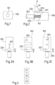
- Figure 1 shows schematically a top view of an end face of a contact part 100, which is designed as a solid component.
- the contact part 100 has a cavity 101, which serves to accommodate an electrical conductor, as will be described below.
- the cavity 101 is designed, for example, as a blind hole, although in the context of the invention it is not important how the cavity is manufactured.
- the cavity can also be produced by forming the contact part or, if the contact part is a cast part, by casting the contact part.
- the cavity can also be designed as a groove.
- the contact part 100 has fastening means (not shown) with which the contact part is connected, for example, to an electric battery or an electric machine.
- the fasteners are screw holes into which a corresponding fastening screw is inserted.
- Figure 2 shows the contact part Figure 1 in a cross section with a conductor 200 inserted into the cavity 101 of the contact part 100.
- the conductor 200 is made from a large number of individual wires or individual strands, which are twisted and / or stranded together and form a stranded conductor.
- the conductor 200 is surrounded by an insulating jacket 202.
- the individual strands 201 are made of aluminum or an aluminum alloy. Since aluminum and its alloys oxidize easily and are covered with an insulating oxide layer, it is of great importance in the practical use of stranded aluminum conductors that all individual strands 201 are contacted in order to make the best possible use of the cross section of the conductor 200 for current transport.
- the insulating jacket 202 is removed at one end of the conductor 200, which is inserted into the cavity 101 of the contact part 100.
- the diameter of the cavity 101 is dimensioned such that the conductor 200 can be inserted into the cavity without the individual strands 201 "brushing up", that is, without one or more individual strands 201 not being accommodated in the cavity 101, but to the outside stand out.
- the electrical connection between the contact part 100 and the conductor 200 is established by a flat, cohesive connection, which, on the one hand, creates a metallurgical connection between the conductor 200 or the stranded conductors 201 and the contact piece 100 and, on the other hand, at the same time creates a metallurgical connection between the individual stranded conductors 201 produces. In this way, good transverse conductivity is created, so that all individual strands 201 contribute to the current transport and the cross section of the conductor 200 is optimally used for the current transport.
- the flat, cohesive connection is produced by friction stir welding.
- the temperature required for a weld is generated through friction.
- This connects the material of the contact part 100 is cohesively bonded to the stranded conductor 200 at a temperature below the melting temperature of the metals used or is welded together by diffusion.
- the pressure applied by the tool 203 and the forming work carried out as a result also contribute to this.
- the tool used in the method accordingly has a friction surface 204, the effectiveness of which is improved by a centrally arranged projecting nose 206.
- the rapidly rotating tool 203 is lowered onto the contact part 100.
- the rotation of the tool 203 is indicated by an arrow R and the lowering movement by an arrow P.
- the tool 203 exerts pressure on the contact part 100, which together with the rotational movement results in the material of the contact part 100 and the individual strands 201 in transition to a plastic state and form a metallurgical material bond with each other.
- the tool 203 When the tool 203 is placed on the contact part 100, the same is advantageously already set in rotation. However, it can also only be set in rotation after it has been placed on the contact part.
- Figure 3A illustrates how a flat connection between the conductor 200 and the contact part 100 is achieved.
- This first method of producing the connection is not part of the invention.
- the tool 203 the diameter of which approximately corresponds to the diameter of the conductor 200 or is larger, is moved along the arrow 301 onto the contact part 100.
- the area of the weld corresponds approximately to the diameter of the tool 203 in one direction and the length of the arrow 301 in the other direction.
- Figure 3B illustrates an alternative procedure for producing the flat connection between the contact part 100 and the conductor 200.
- the tool 203 whose diameter is smaller than the diameter of the conductor 200, is moved along an The XY contour is in Figure 3B indicated by an arrow 302.
- This alternative method is particularly advantageous when the conductor 200 has a comparatively large diameter.
- Figure 3C a further method for producing the flat, cohesive connection between the contact part 100 and the conductor 200.
- the tool 203 is moved on a cycloid along the conductor 200 inserted into the contact part 100.
- the cycloid is created by superimposing a translational movement with a circular movement and is in Figure 3C symbolized by arrow 303.
- This method is also suitable for conductors 200 that have a comparatively large diameter.
- the tool performs other movement patterns on the contact part 100, for example a zigzag line.
- the tool 203 executes movement patterns on the contact part 100 that are generated from a combination of the movement patterns described.
- the direction of lowering of the tool 203 is in the Figures 3A to 3C symbolized by an arrow A into the drawing plane. Accordingly, the tool 203 carries out a movement in the drawing plane towards the contact part 100.
- Figure 4 shows a flowchart of the method for producing a flat, cohesive connection in a general form.
- a first step S1 the conductor 100 is inserted into the cavity 101 in the contact part 100.
- the tool 203 for friction stir welding is lowered onto the contact part 100 and set in rotation if it has not already rotated before lowering.
- the lowered tool 203 is moved on the contact part 100 in a plane that extends substantially perpendicular to the direction in which the lowering of the tool 203 is carried out.
- the individual strands 201 of the conductor 200 are cohesively connected to one another and to the contact part 100, so that a flat, cohesive connection is created.
Landscapes
- Engineering & Computer Science (AREA)
- Manufacturing & Machinery (AREA)
- Mechanical Engineering (AREA)
- Pressure Welding/Diffusion-Bonding (AREA)
- Connections Effected By Soldering, Adhesion, Or Permanent Deformation (AREA)
Claims (7)
- Procédé pour le raccordement électroconducteur d'une pièce de contact (100) avec un conducteur (200), qui comprend une pluralité de fils individuels (201) en aluminium ou en alliage d'aluminium, dans lequel le procédé comprend les étapes suivantes :- insertion (S1) du conducteur (200) dans une cavité (101) dans la pièce de contact (100) ;- abaissement (S2) d'un outil (203) pour un soudage par friction-malaxage sur la pièce de contact (100) ;dans lequel le procédé est caractérisé par les étapes suivantes- déplacement bidimensionnel (S3) de l'outil (203) pour le soudage par friction-malaxage sur la pièce de contact (100) dans le plan qui est globalement perpendiculaire à une direction (A) dans laquelle l'abaissement de l'outil (203) est effectué, ce qui permet d'obtenir un raccordement par liaison de matière plane entre la pièce de contact (100) et le conducteur (200).
- Procédé selon la revendication 1, caractérisé en ce qu'il comprend en outre l'étape suivante :- raccordement par liaison de matière (S3) des fils individuels (201) du conducteur (200) entre eux.
- Procédé selon la revendication 1, caractérisé en ce que le déplacement bidimensionnel de l'outil pour soudage par friction-malaxage a lieu en translation le long d'un contour X-Y (302).
- Procédé selon la revendication 1, caractérisé en ce que le déplacement bidimensionnel de l'outil pour soudage par friction-malaxage est constitué d'une superposition d'un mouvement de translation et d'un mouvement circulaire (303).
- Câble électrique avec un conducteur (200), qui comprend une pluralité de fils individuels (201) en aluminium ou en alliage d'aluminium et qui est relié avec une pièce de contact (100), dans lequel les fils individuels (201) du conducteur (200) sont reliés entre eux et avec la pièce de contact (100) avec un raccordement par liaison de matière, qui est réalisée à l'aide d'un soudage par friction-malaxage selon l'une des revendications 1 à 4.
- Câble électrique selon la revendication 5, caractérisé en ce que la pièce de contact (100) est réalisée à base de cuivre ou d'aluminium ou d'un alliage de ceux-ci.
- Câble électrique selon la revendication 5 ou 6, caractérisé en ce que la pièce de contact (100) est un rail conducteur.
Priority Applications (3)
| Application Number | Priority Date | Filing Date | Title |
|---|---|---|---|
| EP19305980.5A EP3771042B1 (fr) | 2019-07-26 | 2019-07-26 | Fabrication d'un raccordement plat entre un conducteur électrique et une pièce de contact |
| CN202010710212.4A CN112310776B (zh) | 2019-07-26 | 2020-07-22 | 将接触件导电地连接至导体的方法以及电线 |
| US16/937,082 US11936152B2 (en) | 2019-07-26 | 2020-07-23 | Production of a planar connection between an electrical conductor and a contact piece |
Applications Claiming Priority (1)
| Application Number | Priority Date | Filing Date | Title |
|---|---|---|---|
| EP19305980.5A EP3771042B1 (fr) | 2019-07-26 | 2019-07-26 | Fabrication d'un raccordement plat entre un conducteur électrique et une pièce de contact |
Publications (2)
| Publication Number | Publication Date |
|---|---|
| EP3771042A1 EP3771042A1 (fr) | 2021-01-27 |
| EP3771042B1 true EP3771042B1 (fr) | 2023-10-04 |
Family
ID=67551316
Family Applications (1)
| Application Number | Title | Priority Date | Filing Date |
|---|---|---|---|
| EP19305980.5A Active EP3771042B1 (fr) | 2019-07-26 | 2019-07-26 | Fabrication d'un raccordement plat entre un conducteur électrique et une pièce de contact |
Country Status (3)
| Country | Link |
|---|---|
| US (1) | US11936152B2 (fr) |
| EP (1) | EP3771042B1 (fr) |
| CN (1) | CN112310776B (fr) |
Families Citing this family (2)
| Publication number | Priority date | Publication date | Assignee | Title |
|---|---|---|---|---|
| FR3098745B1 (fr) * | 2019-07-15 | 2022-06-24 | Nidec Psa Emotors | Procédé de soudage sans apport de matière |
| CN115070196B (zh) * | 2022-08-08 | 2023-05-26 | 南昌航空大学 | 一种导电铜排与多股铜线焊接接头及搅拌摩擦焊接方法 |
Family Cites Families (10)
| Publication number | Priority date | Publication date | Assignee | Title |
|---|---|---|---|---|
| JP3823780B2 (ja) * | 2001-08-31 | 2006-09-20 | 株式会社日立製作所 | 摩擦攪拌接合方法 |
| JP4267899B2 (ja) * | 2002-11-11 | 2009-05-27 | 古河電気工業株式会社 | アルミニウム線状体の接続方法 |
| JP2009187683A (ja) * | 2008-02-02 | 2009-08-20 | Sumitomo Light Metal Ind Ltd | アルミニウム製コネクタの製造方法 |
| JP4875718B2 (ja) * | 2009-01-21 | 2012-02-15 | 株式会社井上製作所 | 可撓導体および可撓導体の製造方法 |
| EP2735397B1 (fr) | 2012-11-23 | 2018-01-17 | Nexans | Procédé de connection électrique d'une pièce de contact à un conducteur électrique |
| DE102013219150A1 (de) * | 2013-09-24 | 2015-04-09 | Elringklinger Ag | Verfahren zum Herstellen einer elektrisch leitenden Verbindung zwischen einer elektrischen Leitung und einem elektrisch leitenden Bauteil |
| US10027042B2 (en) * | 2014-10-28 | 2018-07-17 | Afl Telecommunications Llc | Swage high voltage cable terminal |
| US10583519B2 (en) * | 2016-08-12 | 2020-03-10 | The Boeing Company | Friction stir welding method and assembly |
| DE102018212158A1 (de) * | 2018-07-20 | 2020-01-23 | Technische Universität Ilmenau | Verfahren zum Zusammenfügen zweier oder mehrerer elektrischer Leiter, Vorrichtung zum Zusammenfügen zweier oder mehrerer elektrischer Leiter und elektrische Verbindung zwischen zwei oder mehr Leitern |
| DE102019104318C5 (de) * | 2019-02-20 | 2023-06-22 | Auto-Kabel Management Gmbh | Elektrischer Leiter sowie Verfahren zur Herstellung eines elektrischen Leiters |
-
2019
- 2019-07-26 EP EP19305980.5A patent/EP3771042B1/fr active Active
-
2020
- 2020-07-22 CN CN202010710212.4A patent/CN112310776B/zh active Active
- 2020-07-23 US US16/937,082 patent/US11936152B2/en active Active
Also Published As
| Publication number | Publication date |
|---|---|
| US11936152B2 (en) | 2024-03-19 |
| EP3771042A1 (fr) | 2021-01-27 |
| CN112310776A (zh) | 2021-02-02 |
| US20210044066A1 (en) | 2021-02-11 |
| CN112310776B (zh) | 2024-04-26 |
Similar Documents
| Publication | Publication Date | Title |
|---|---|---|
| DE10358686B4 (de) | Crimpkontaktelement | |
| DE102018009206B3 (de) | Verbindungsbauteil zur Verbindung von elektrischen Leitern einer hairpin-Wicklung eines Stators einer Elektromaschine sowie Verfahren zur Herstellung dieser Verbindung | |
| EP2362491B1 (fr) | Procédé de connexion d'une conduite électrique avec un élément de raccordement électrique | |
| DE102014012489B4 (de) | Anschlussteil für Aluminiumleitungen | |
| DE19908031A1 (de) | Verbindung eines elektrischen Aluminiumkabels mit einem aus Kupfer oder dergleichen Metall bestehenden Anschlußteil | |
| EP2735397A1 (fr) | Procédé de connection électrique d'une pièce de contact à un conducteur électrique et système associé | |
| DE112011100268T5 (de) | Verfahren zum Bearbeiten eines Drahtendes | |
| EP3769370A1 (fr) | Procédé d'établissement d'une liaison entre un élément de raccordement électrique destiné à un réseau de bord de véhicule automobile et un câble du réseau de bord de véhicule automobile | |
| EP2371036A1 (fr) | Liaison de contact électrique et procédé pour réaliser une liaison de contact électrique | |
| DE102011089207C5 (de) | Verfahren zum Kontaktieren einer Litzenleitung mit einem Kontakt | |
| EP3609023B1 (fr) | Procédé et dispositif de fabrication d'un raccordement électrique et conduite électrique | |
| DE102011085704A1 (de) | Hochstrom-Steckverbinder für Kraftfahrzeuganwendungen | |
| EP3771042B1 (fr) | Fabrication d'un raccordement plat entre un conducteur électrique et une pièce de contact | |
| DE112016002171T5 (de) | Anschluss zur leitungsverbindung und verfahren zur verbindung des anschlusses mit der leitung | |
| EP3454420B1 (fr) | Procédé de raccordement d'une conduite d'aluminium électrique à un tube d'aluminium | |
| DE102014004127B4 (de) | Verfahren zum Verbinden einer elektrischen Leitung mit einem metallischen Kontaktelement, Verbindungselement sowie Sonotrode | |
| WO2018050392A1 (fr) | Rotor électrique et procédé d'établissement d'un contact électrique entre un enroulement de rotor et une patte de contact | |
| EP3206258A1 (fr) | Système de fabrication d'un raccordement électrique, raccordement électrique et son procédé de fabrication | |
| WO2011069744A1 (fr) | Élément de liaison | |
| EP3451455B1 (fr) | Procédé de fabrication d'une liaison électrique et une ligne électrique | |
| EP2887459B1 (fr) | Procédé de liaison électrique d'un conducteur à base d'aluminium avec une pièce de contact | |
| EP2996200A1 (fr) | Élement de liaison | |
| DE102011089206B4 (de) | Verfahren zum Kontaktieren einer Litzenleitung mit einem Kontakt | |
| EP2717275B1 (fr) | Procédé de fabrication d'un fil supraconducteur, notamment en utilisant une brasure sans plomb | |
| DE102025102727A1 (de) | Verbindungs-Adapter |
Legal Events
| Date | Code | Title | Description |
|---|---|---|---|
| PUAI | Public reference made under article 153(3) epc to a published international application that has entered the european phase |
Free format text: ORIGINAL CODE: 0009012 |
|
| STAA | Information on the status of an ep patent application or granted ep patent |
Free format text: STATUS: THE APPLICATION HAS BEEN PUBLISHED |
|
| AK | Designated contracting states |
Kind code of ref document: A1 Designated state(s): AL AT BE BG CH CY CZ DE DK EE ES FI FR GB GR HR HU IE IS IT LI LT LU LV MC MK MT NL NO PL PT RO RS SE SI SK SM TR |
|
| AX | Request for extension of the european patent |
Extension state: BA ME |
|
| STAA | Information on the status of an ep patent application or granted ep patent |
Free format text: STATUS: REQUEST FOR EXAMINATION WAS MADE |
|
| 17P | Request for examination filed |
Effective date: 20210727 |
|
| RBV | Designated contracting states (corrected) |
Designated state(s): AL AT BE BG CH CY CZ DE DK EE ES FI FR GB GR HR HU IE IS IT LI LT LU LV MC MK MT NL NO PL PT RO RS SE SI SK SM TR |
|
| GRAP | Despatch of communication of intention to grant a patent |
Free format text: ORIGINAL CODE: EPIDOSNIGR1 |
|
| STAA | Information on the status of an ep patent application or granted ep patent |
Free format text: STATUS: GRANT OF PATENT IS INTENDED |
|
| RIC1 | Information provided on ipc code assigned before grant |
Ipc: B23K 101/32 20060101ALN20221116BHEP Ipc: B23K 20/00 20060101ALI20221116BHEP Ipc: B23K 20/12 20060101ALI20221116BHEP Ipc: H01R 43/02 20060101ALI20221116BHEP Ipc: H01R 4/02 20060101AFI20221116BHEP |
|
| INTG | Intention to grant announced |
Effective date: 20221215 |
|
| GRAJ | Information related to disapproval of communication of intention to grant by the applicant or resumption of examination proceedings by the epo deleted |
Free format text: ORIGINAL CODE: EPIDOSDIGR1 |
|
| STAA | Information on the status of an ep patent application or granted ep patent |
Free format text: STATUS: REQUEST FOR EXAMINATION WAS MADE |
|
| GRAP | Despatch of communication of intention to grant a patent |
Free format text: ORIGINAL CODE: EPIDOSNIGR1 |
|
| STAA | Information on the status of an ep patent application or granted ep patent |
Free format text: STATUS: GRANT OF PATENT IS INTENDED |
|
| INTC | Intention to grant announced (deleted) | ||
| RIC1 | Information provided on ipc code assigned before grant |
Ipc: B23K 101/32 20060101ALN20230426BHEP Ipc: B23K 20/00 20060101ALI20230426BHEP Ipc: B23K 20/12 20060101ALI20230426BHEP Ipc: H01R 43/02 20060101ALI20230426BHEP Ipc: H01R 4/02 20060101AFI20230426BHEP |
|
| INTG | Intention to grant announced |
Effective date: 20230517 |
|
| GRAS | Grant fee paid |
Free format text: ORIGINAL CODE: EPIDOSNIGR3 |
|
| GRAA | (expected) grant |
Free format text: ORIGINAL CODE: 0009210 |
|
| STAA | Information on the status of an ep patent application or granted ep patent |
Free format text: STATUS: THE PATENT HAS BEEN GRANTED |
|
| AK | Designated contracting states |
Kind code of ref document: B1 Designated state(s): AL AT BE BG CH CY CZ DE DK EE ES FI FR GB GR HR HU IE IS IT LI LT LU LV MC MK MT NL NO PL PT RO RS SE SI SK SM TR |
|
| REG | Reference to a national code |
Ref country code: GB Ref legal event code: FG4D Free format text: NOT ENGLISH |
|
| REG | Reference to a national code |
Ref country code: CH Ref legal event code: EP |
|
| REG | Reference to a national code |
Ref country code: IE Ref legal event code: FG4D Free format text: LANGUAGE OF EP DOCUMENT: GERMAN |
|
| REG | Reference to a national code |
Ref country code: DE Ref legal event code: R096 Ref document number: 502019009550 Country of ref document: DE |
|
| REG | Reference to a national code |
Ref country code: LT Ref legal event code: MG9D |
|
| REG | Reference to a national code |
Ref country code: NL Ref legal event code: MP Effective date: 20231004 |
|
| PG25 | Lapsed in a contracting state [announced via postgrant information from national office to epo] |
Ref country code: NL Free format text: LAPSE BECAUSE OF FAILURE TO SUBMIT A TRANSLATION OF THE DESCRIPTION OR TO PAY THE FEE WITHIN THE PRESCRIBED TIME-LIMIT Effective date: 20231004 |
|
| PG25 | Lapsed in a contracting state [announced via postgrant information from national office to epo] |
Ref country code: GR Free format text: LAPSE BECAUSE OF FAILURE TO SUBMIT A TRANSLATION OF THE DESCRIPTION OR TO PAY THE FEE WITHIN THE PRESCRIBED TIME-LIMIT Effective date: 20240105 |
|
| PG25 | Lapsed in a contracting state [announced via postgrant information from national office to epo] |
Ref country code: IS Free format text: LAPSE BECAUSE OF FAILURE TO SUBMIT A TRANSLATION OF THE DESCRIPTION OR TO PAY THE FEE WITHIN THE PRESCRIBED TIME-LIMIT Effective date: 20240204 |
|
| PG25 | Lapsed in a contracting state [announced via postgrant information from national office to epo] |
Ref country code: LT Free format text: LAPSE BECAUSE OF FAILURE TO SUBMIT A TRANSLATION OF THE DESCRIPTION OR TO PAY THE FEE WITHIN THE PRESCRIBED TIME-LIMIT Effective date: 20231004 |
|
| PG25 | Lapsed in a contracting state [announced via postgrant information from national office to epo] |
Ref country code: ES Free format text: LAPSE BECAUSE OF FAILURE TO SUBMIT A TRANSLATION OF THE DESCRIPTION OR TO PAY THE FEE WITHIN THE PRESCRIBED TIME-LIMIT Effective date: 20231004 |
|
| PG25 | Lapsed in a contracting state [announced via postgrant information from national office to epo] |
Ref country code: LT Free format text: LAPSE BECAUSE OF FAILURE TO SUBMIT A TRANSLATION OF THE DESCRIPTION OR TO PAY THE FEE WITHIN THE PRESCRIBED TIME-LIMIT Effective date: 20231004 Ref country code: IS Free format text: LAPSE BECAUSE OF FAILURE TO SUBMIT A TRANSLATION OF THE DESCRIPTION OR TO PAY THE FEE WITHIN THE PRESCRIBED TIME-LIMIT Effective date: 20240204 Ref country code: GR Free format text: LAPSE BECAUSE OF FAILURE TO SUBMIT A TRANSLATION OF THE DESCRIPTION OR TO PAY THE FEE WITHIN THE PRESCRIBED TIME-LIMIT Effective date: 20240105 Ref country code: ES Free format text: LAPSE BECAUSE OF FAILURE TO SUBMIT A TRANSLATION OF THE DESCRIPTION OR TO PAY THE FEE WITHIN THE PRESCRIBED TIME-LIMIT Effective date: 20231004 Ref country code: BG Free format text: LAPSE BECAUSE OF FAILURE TO SUBMIT A TRANSLATION OF THE DESCRIPTION OR TO PAY THE FEE WITHIN THE PRESCRIBED TIME-LIMIT Effective date: 20240104 Ref country code: PT Free format text: LAPSE BECAUSE OF FAILURE TO SUBMIT A TRANSLATION OF THE DESCRIPTION OR TO PAY THE FEE WITHIN THE PRESCRIBED TIME-LIMIT Effective date: 20240205 |
|
| PG25 | Lapsed in a contracting state [announced via postgrant information from national office to epo] |
Ref country code: SE Free format text: LAPSE BECAUSE OF FAILURE TO SUBMIT A TRANSLATION OF THE DESCRIPTION OR TO PAY THE FEE WITHIN THE PRESCRIBED TIME-LIMIT Effective date: 20231004 Ref country code: RS Free format text: LAPSE BECAUSE OF FAILURE TO SUBMIT A TRANSLATION OF THE DESCRIPTION OR TO PAY THE FEE WITHIN THE PRESCRIBED TIME-LIMIT Effective date: 20231004 Ref country code: PL Free format text: LAPSE BECAUSE OF FAILURE TO SUBMIT A TRANSLATION OF THE DESCRIPTION OR TO PAY THE FEE WITHIN THE PRESCRIBED TIME-LIMIT Effective date: 20231004 Ref country code: NO Free format text: LAPSE BECAUSE OF FAILURE TO SUBMIT A TRANSLATION OF THE DESCRIPTION OR TO PAY THE FEE WITHIN THE PRESCRIBED TIME-LIMIT Effective date: 20240104 Ref country code: LV Free format text: LAPSE BECAUSE OF FAILURE TO SUBMIT A TRANSLATION OF THE DESCRIPTION OR TO PAY THE FEE WITHIN THE PRESCRIBED TIME-LIMIT Effective date: 20231004 Ref country code: HR Free format text: LAPSE BECAUSE OF FAILURE TO SUBMIT A TRANSLATION OF THE DESCRIPTION OR TO PAY THE FEE WITHIN THE PRESCRIBED TIME-LIMIT Effective date: 20231004 |
|
| REG | Reference to a national code |
Ref country code: DE Ref legal event code: R097 Ref document number: 502019009550 Country of ref document: DE |
|
| PG25 | Lapsed in a contracting state [announced via postgrant information from national office to epo] |
Ref country code: DK Free format text: LAPSE BECAUSE OF FAILURE TO SUBMIT A TRANSLATION OF THE DESCRIPTION OR TO PAY THE FEE WITHIN THE PRESCRIBED TIME-LIMIT Effective date: 20231004 |
|
| PG25 | Lapsed in a contracting state [announced via postgrant information from national office to epo] |
Ref country code: CZ Free format text: LAPSE BECAUSE OF FAILURE TO SUBMIT A TRANSLATION OF THE DESCRIPTION OR TO PAY THE FEE WITHIN THE PRESCRIBED TIME-LIMIT Effective date: 20231004 |
|
| PG25 | Lapsed in a contracting state [announced via postgrant information from national office to epo] |
Ref country code: SK Free format text: LAPSE BECAUSE OF FAILURE TO SUBMIT A TRANSLATION OF THE DESCRIPTION OR TO PAY THE FEE WITHIN THE PRESCRIBED TIME-LIMIT Effective date: 20231004 |
|
| PG25 | Lapsed in a contracting state [announced via postgrant information from national office to epo] |
Ref country code: SM Free format text: LAPSE BECAUSE OF FAILURE TO SUBMIT A TRANSLATION OF THE DESCRIPTION OR TO PAY THE FEE WITHIN THE PRESCRIBED TIME-LIMIT Effective date: 20231004 Ref country code: SK Free format text: LAPSE BECAUSE OF FAILURE TO SUBMIT A TRANSLATION OF THE DESCRIPTION OR TO PAY THE FEE WITHIN THE PRESCRIBED TIME-LIMIT Effective date: 20231004 Ref country code: RO Free format text: LAPSE BECAUSE OF FAILURE TO SUBMIT A TRANSLATION OF THE DESCRIPTION OR TO PAY THE FEE WITHIN THE PRESCRIBED TIME-LIMIT Effective date: 20231004 Ref country code: IT Free format text: LAPSE BECAUSE OF FAILURE TO SUBMIT A TRANSLATION OF THE DESCRIPTION OR TO PAY THE FEE WITHIN THE PRESCRIBED TIME-LIMIT Effective date: 20231004 Ref country code: EE Free format text: LAPSE BECAUSE OF FAILURE TO SUBMIT A TRANSLATION OF THE DESCRIPTION OR TO PAY THE FEE WITHIN THE PRESCRIBED TIME-LIMIT Effective date: 20231004 Ref country code: DK Free format text: LAPSE BECAUSE OF FAILURE TO SUBMIT A TRANSLATION OF THE DESCRIPTION OR TO PAY THE FEE WITHIN THE PRESCRIBED TIME-LIMIT Effective date: 20231004 Ref country code: CZ Free format text: LAPSE BECAUSE OF FAILURE TO SUBMIT A TRANSLATION OF THE DESCRIPTION OR TO PAY THE FEE WITHIN THE PRESCRIBED TIME-LIMIT Effective date: 20231004 |
|
| PLBE | No opposition filed within time limit |
Free format text: ORIGINAL CODE: 0009261 |
|
| STAA | Information on the status of an ep patent application or granted ep patent |
Free format text: STATUS: NO OPPOSITION FILED WITHIN TIME LIMIT |
|
| 26N | No opposition filed |
Effective date: 20240705 |
|
| PG25 | Lapsed in a contracting state [announced via postgrant information from national office to epo] |
Ref country code: SI Free format text: LAPSE BECAUSE OF FAILURE TO SUBMIT A TRANSLATION OF THE DESCRIPTION OR TO PAY THE FEE WITHIN THE PRESCRIBED TIME-LIMIT Effective date: 20231004 |
|
| PG25 | Lapsed in a contracting state [announced via postgrant information from national office to epo] |
Ref country code: SI Free format text: LAPSE BECAUSE OF FAILURE TO SUBMIT A TRANSLATION OF THE DESCRIPTION OR TO PAY THE FEE WITHIN THE PRESCRIBED TIME-LIMIT Effective date: 20231004 |
|
| PG25 | Lapsed in a contracting state [announced via postgrant information from national office to epo] |
Ref country code: MC Free format text: LAPSE BECAUSE OF FAILURE TO SUBMIT A TRANSLATION OF THE DESCRIPTION OR TO PAY THE FEE WITHIN THE PRESCRIBED TIME-LIMIT Effective date: 20231004 |
|
| REG | Reference to a national code |
Ref country code: CH Ref legal event code: PL |
|
| PG25 | Lapsed in a contracting state [announced via postgrant information from national office to epo] |
Ref country code: LU Free format text: LAPSE BECAUSE OF NON-PAYMENT OF DUE FEES Effective date: 20240726 |
|
| PG25 | Lapsed in a contracting state [announced via postgrant information from national office to epo] |
Ref country code: LU Free format text: LAPSE BECAUSE OF NON-PAYMENT OF DUE FEES Effective date: 20240726 |
|
| PG25 | Lapsed in a contracting state [announced via postgrant information from national office to epo] |
Ref country code: CH Free format text: LAPSE BECAUSE OF NON-PAYMENT OF DUE FEES Effective date: 20240731 Ref country code: BE Free format text: LAPSE BECAUSE OF NON-PAYMENT OF DUE FEES Effective date: 20240731 |
|
| REG | Reference to a national code |
Ref country code: BE Ref legal event code: MM Effective date: 20240731 |
|
| PG25 | Lapsed in a contracting state [announced via postgrant information from national office to epo] |
Ref country code: IE Free format text: LAPSE BECAUSE OF NON-PAYMENT OF DUE FEES Effective date: 20240726 |
|
| REG | Reference to a national code |
Ref country code: AT Ref legal event code: MM01 Ref document number: 1618718 Country of ref document: AT Kind code of ref document: T Effective date: 20240726 |
|
| PG25 | Lapsed in a contracting state [announced via postgrant information from national office to epo] |
Ref country code: FI Free format text: LAPSE BECAUSE OF FAILURE TO SUBMIT A TRANSLATION OF THE DESCRIPTION OR TO PAY THE FEE WITHIN THE PRESCRIBED TIME-LIMIT Effective date: 20231004 |
|
| PGFP | Annual fee paid to national office [announced via postgrant information from national office to epo] |
Ref country code: DE Payment date: 20250722 Year of fee payment: 7 |
|
| PGFP | Annual fee paid to national office [announced via postgrant information from national office to epo] |
Ref country code: GB Payment date: 20250722 Year of fee payment: 7 |
|
| PG25 | Lapsed in a contracting state [announced via postgrant information from national office to epo] |
Ref country code: AT Free format text: LAPSE BECAUSE OF NON-PAYMENT OF DUE FEES Effective date: 20240726 |
|
| PGFP | Annual fee paid to national office [announced via postgrant information from national office to epo] |
Ref country code: FR Payment date: 20250725 Year of fee payment: 7 |
|
| PG25 | Lapsed in a contracting state [announced via postgrant information from national office to epo] |
Ref country code: CY Free format text: LAPSE BECAUSE OF FAILURE TO SUBMIT A TRANSLATION OF THE DESCRIPTION OR TO PAY THE FEE WITHIN THE PRESCRIBED TIME-LIMIT; INVALID AB INITIO Effective date: 20190726 |
|
| PG25 | Lapsed in a contracting state [announced via postgrant information from national office to epo] |
Ref country code: HU Free format text: LAPSE BECAUSE OF FAILURE TO SUBMIT A TRANSLATION OF THE DESCRIPTION OR TO PAY THE FEE WITHIN THE PRESCRIBED TIME-LIMIT; INVALID AB INITIO Effective date: 20190726 |