EP3771793A1 - Ferrure pour une porte coulissante - Google Patents
Ferrure pour une porte coulissante Download PDFInfo
- Publication number
- EP3771793A1 EP3771793A1 EP20173684.0A EP20173684A EP3771793A1 EP 3771793 A1 EP3771793 A1 EP 3771793A1 EP 20173684 A EP20173684 A EP 20173684A EP 3771793 A1 EP3771793 A1 EP 3771793A1
- Authority
- EP
- European Patent Office
- Prior art keywords
- connecting rod
- carriage
- connecting device
- fitting according
- fitting
- Prior art date
- Legal status (The legal status is an assumption and is not a legal conclusion. Google has not performed a legal analysis and makes no representation as to the accuracy of the status listed.)
- Granted
Links
Images


Classifications
-
- E—FIXED CONSTRUCTIONS
- E05—LOCKS; KEYS; WINDOW OR DOOR FITTINGS; SAFES
- E05D—HINGES OR SUSPENSION DEVICES FOR DOORS, WINDOWS OR WINGS
- E05D15/00—Suspension arrangements for wings
- E05D15/56—Suspension arrangements for wings with successive different movements
- E05D15/565—Suspension arrangements for wings with successive different movements for raising wings before sliding
-
- E—FIXED CONSTRUCTIONS
- E05—LOCKS; KEYS; WINDOW OR DOOR FITTINGS; SAFES
- E05Y—INDEXING SCHEME ASSOCIATED WITH SUBCLASSES E05D AND E05F, RELATING TO CONSTRUCTION ELEMENTS, ELECTRIC CONTROL, POWER SUPPLY, POWER SIGNAL OR TRANSMISSION, USER INTERFACES, MOUNTING OR COUPLING, DETAILS, ACCESSORIES, AUXILIARY OPERATIONS NOT OTHERWISE PROVIDED FOR, APPLICATION THEREOF
- E05Y2600/00—Mounting or coupling arrangements for elements provided for in this subclass
- E05Y2600/10—Adjustable
- E05Y2600/14—Adjustable with position retaining means
-
- E—FIXED CONSTRUCTIONS
- E05—LOCKS; KEYS; WINDOW OR DOOR FITTINGS; SAFES
- E05Y—INDEXING SCHEME ASSOCIATED WITH SUBCLASSES E05D AND E05F, RELATING TO CONSTRUCTION ELEMENTS, ELECTRIC CONTROL, POWER SUPPLY, POWER SIGNAL OR TRANSMISSION, USER INTERFACES, MOUNTING OR COUPLING, DETAILS, ACCESSORIES, AUXILIARY OPERATIONS NOT OTHERWISE PROVIDED FOR, APPLICATION THEREOF
- E05Y2600/00—Mounting or coupling arrangements for elements provided for in this subclass
- E05Y2600/50—Mounting methods; Positioning
- E05Y2600/502—Clamping
-
- E—FIXED CONSTRUCTIONS
- E05—LOCKS; KEYS; WINDOW OR DOOR FITTINGS; SAFES
- E05Y—INDEXING SCHEME ASSOCIATED WITH SUBCLASSES E05D AND E05F, RELATING TO CONSTRUCTION ELEMENTS, ELECTRIC CONTROL, POWER SUPPLY, POWER SIGNAL OR TRANSMISSION, USER INTERFACES, MOUNTING OR COUPLING, DETAILS, ACCESSORIES, AUXILIARY OPERATIONS NOT OTHERWISE PROVIDED FOR, APPLICATION THEREOF
- E05Y2600/00—Mounting or coupling arrangements for elements provided for in this subclass
- E05Y2600/50—Mounting methods; Positioning
- E05Y2600/52—Toolless
- E05Y2600/528—Hooking, e.g. using bayonets; Locking
-
- E—FIXED CONSTRUCTIONS
- E05—LOCKS; KEYS; WINDOW OR DOOR FITTINGS; SAFES
- E05Y—INDEXING SCHEME ASSOCIATED WITH SUBCLASSES E05D AND E05F, RELATING TO CONSTRUCTION ELEMENTS, ELECTRIC CONTROL, POWER SUPPLY, POWER SIGNAL OR TRANSMISSION, USER INTERFACES, MOUNTING OR COUPLING, DETAILS, ACCESSORIES, AUXILIARY OPERATIONS NOT OTHERWISE PROVIDED FOR, APPLICATION THEREOF
- E05Y2800/00—Details, accessories and auxiliary operations not otherwise provided for
- E05Y2800/26—Form or shape
- E05Y2800/292—Form or shape having apertures
-
- E—FIXED CONSTRUCTIONS
- E05—LOCKS; KEYS; WINDOW OR DOOR FITTINGS; SAFES
- E05Y—INDEXING SCHEME ASSOCIATED WITH SUBCLASSES E05D AND E05F, RELATING TO CONSTRUCTION ELEMENTS, ELECTRIC CONTROL, POWER SUPPLY, POWER SIGNAL OR TRANSMISSION, USER INTERFACES, MOUNTING OR COUPLING, DETAILS, ACCESSORIES, AUXILIARY OPERATIONS NOT OTHERWISE PROVIDED FOR, APPLICATION THEREOF
- E05Y2900/00—Application of doors, windows, wings or fittings thereof
- E05Y2900/10—Application of doors, windows, wings or fittings thereof for buildings or parts thereof
- E05Y2900/13—Type of wing
- E05Y2900/132—Doors
Definitions
- the present invention relates to a fitting for a sliding door, in particular a lift-and-slide door, with a first carriage which can be moved along a rail via at least one roller, and a second carriage which can be experienced via at least one roller along the rail, with A wing of the sliding door is supported on the at least two carriages and a connecting rod is arranged between the first carriage and the second carriage, which is fixed to the first carriage via a first connecting device and on the second carriage via a second connecting device.
- the EP 1 298 272 B1 discloses a carriage assembly of a fitting for lift and slide doors, in which a coupling rod with a circular cross section is provided between two carriages.
- the coupling rod is fixed to a carriage at opposite ends, with threaded openings with screws being provided on the connecting devices for this purpose.
- the coupling rod takes up a comparatively large amount of installation space, and the assembly is complex due to the fastening mechanism.
- the coupling rod has a toothing at one end portion which can be brought into engagement with a toothing on a connecting device of the carriage. This is intended to simplify assembly, but the production of the toothing is complex.
- the coupling rod can only be fixed to the toothing of the connecting device in a certain grid dimension.
- the connecting rod is in at least two different positions, at least on the first connecting device can be fixed to the first carriage. This allows you to choose during assembly at which position of the connecting device the connecting rod is fixed, so that the connecting rod is determined depending on the profile geometry in the area of the rail and the requirements for the installation space, the expected loads and the distance between the two carriages can be. This allows the fitting with the connecting rod or coupling rod to be used flexibly for different profile geometries and sliding sashes, since the position of the connecting rod can be designed differently relative to the carriage.
- the connecting rod can preferably also be fixed in at least two different positions on the second connecting device of the second carriage.
- the first connecting device and the second connecting device can have mirror-symmetrical positions relative to a central vertical plane on the connecting rod for fastening the connecting rod, so that the connecting rod extends essentially parallel to the longitudinal direction of the rail.
- the first connecting device has a block attached to the first carriage, which is coupled to the carriage via an articulated connection, for example, with at least two offset receptacles being provided on the block for inserting or applying one end of the connecting rod.
- the connecting rod can also be mounted in three different positions on the connecting device.
- the connecting rod is preferably rectangular in cross-section, with a main surface being able to be fixed at different angles on the first connecting device.
- the main area of the connecting rod is the area that takes up the largest surface.
- two main surfaces are thus provided which are formed parallel to one another and can be fixed at different angles via the connecting device, for example in the mounted position of the fitting essentially vertically or essentially horizontally.
- openings with different opening geometries are formed on the connecting rod, through which different locking elements can be used for fixing to the first connecting device.
- a first locking element can be designed as a rotatable bayonet lock, the associated opening having a cross section deviating from the circular shape, for example with one or two recesses projecting radially from an edge.
- a second locking element can be formed, for example, by a non-positively or positively securable pin which can be inserted into a circular opening on the connecting rod. Appropriate design of the geometries can ensure that only the correct locking element can be inserted into the respective opening.
- the fitting according to the invention is used in particular for a sliding door that can be moved along a rail on a frame.
- the sliding door can be designed as a lift-slide door, in which a wing is raised when unlocking and lowered to lock.
- the fitting can also be used without this lifting function.
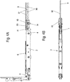
- a fitting 1 comprises a first carriage 2 which can be moved via two rotatable rollers 4 and on which a height-adjustable support 6 is provided for a leaf of a sliding door. Furthermore, the fitting 1 comprises a second carriage 3, which can be moved over two rollers 5 and has a support 7 which is also adjustable in height and serves to support a sash, not shown.
- the supports 6 and 7 are adjustable via an actuating mechanism 8, as shown, for example, in FIG EP 1 298 272 B1 is described.
- a first connecting device 10 is fixed on the end face of the first carriage 2 and is connected to the carriage 2 in an articulated manner about an axis 11.
- a second connecting device 12 is articulated to the carriage 3 via an axle 13.
- a connecting rod 9 is arranged between the two connecting devices 10 and 12 and holds the first carriage 2 and the second carriage 3 at a predetermined distance.
- the connecting rod 9 has a rectangular cross section and a main surface 92 is formed parallel to the longitudinal direction and extends horizontally.
- openings 90 and 91 are recessed in the main surface 92.
- the openings 90 and 91 have different opening geometries, the openings 91 being circular and the openings 90 having a circular base area on which two radially protruding recesses are formed.
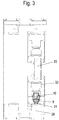
- the openings 90 can be used to fix the connecting rod 9 via a bayonet catch, as shown in FIG Figures 2A and 2B is shown.
- the bayonet catch comprises a rotatable locking element 14 which has two radially protruding projections which, when aligned parallel to the longitudinal direction of the connecting rod 9, can be pushed through the opening 90 in order to then, after rotating, the connecting rod 9 in a form-fitting and optionally also force-fitting manner on the connecting device 10 to fix.
- the rotatable locking element 14 is arranged on an underside of the block-shaped connecting device 10.
- Figure 3 is a section through the carriage of the Figure 2 shown in an assembled position.
- a rail 21, on which the rollers 4 and 5 of the fitting 1 can be moved, is fixed to a frame 20.
- the connecting rod 9, which is rectangular in cross-section, is arranged slightly above the rail 21 and can hold the carriages 2 and 3 at a predetermined distance from one another.
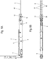
- FIG. 4A and 4B shows the first carriage 2 with the first connecting device 10, in which the connecting rod 9 is in a different position than in FIG Figure 2 is fixed.
- the main surface 92 of the connecting rod 9 is no longer aligned horizontally, but vertically, so that only the narrow longitudinal edges of the connecting rod 9 are positioned horizontally, so that the space requirement in the horizontal direction is significantly less.
- the connecting rod 9 is inserted with one end portion into a slot-shaped receptacle on the connecting device 10 and via a locking element 50, which for example is designed as a pin, fixed.
- the locking element 50 extends through a circular opening 91.
- the locking element 14 on the connecting device 10 is inoperative.
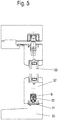
- Figure 5 is the fitting of the Figure 4 shown in a built-in position.
- a rail 31 on which the rollers 4 and 5 of the carriages 2 and 3 can be moved is fixed on a frame 30.
- the connecting rod 9 can be seen, the main surface of which is oriented vertically and thus the lateral installation space next to the connecting rod 9 can be used for other purposes.
- the connecting rod 9 is arranged in a groove of a wing 32 on which a filling element 33 is held.
- the first carriage 2 is shown with the first connecting device 10, in which the connecting rod 9 is fixed at a third position.
- the connecting rod 9 is similar to Figure 2 again aligned horizontally with the main surface 92, but not fixed to the locking element 14, but pushed into a receptacle on the connecting device 10 above the locking element 14.
- the slot-shaped receptacle 28 can be seen in this position, which is used for fixing the connecting rod 9 according to FIG Figure 4A serves.
- the connecting device 10 comprises a block, in particular one Cast block made of plastic or metal, which has the rotatable locking element 14 on an underside 26, which has two radially outwardly protruding projections 15 which can be pushed through the openings 90 on the connecting rod 9 to connect the connecting rod 9 in the manner of a bayonet lock to the To fix connecting device 10.
- a receptacle for an end section of the connecting rod 9, against which the connecting rod can be placed, is thus formed on the underside 26.
- a receptacle 16 for inserting one end of the connecting rod 9 is formed, which is rectangular in cross section and extends horizontally in the assembled position. This receptacle 16 is used to fix the connecting rod 9 via a clamping device.
- the connecting device 10 comprises a web 19 with an opening 18 through which an axle 11 extends in order to fix the connecting device 10 in an articulated manner on the first carriage 2.
Landscapes
- Engineering & Computer Science (AREA)
- Mechanical Engineering (AREA)
- Support Devices For Sliding Doors (AREA)
Applications Claiming Priority (1)
| Application Number | Priority Date | Filing Date | Title |
|---|---|---|---|
| DE102019120584.0A DE102019120584A1 (de) | 2019-07-30 | 2019-07-30 | Beschlag für eine Schiebetür |
Publications (2)
| Publication Number | Publication Date |
|---|---|
| EP3771793A1 true EP3771793A1 (fr) | 2021-02-03 |
| EP3771793B1 EP3771793B1 (fr) | 2023-11-22 |
Family
ID=70680262
Family Applications (1)
| Application Number | Title | Priority Date | Filing Date |
|---|---|---|---|
| EP20173684.0A Active EP3771793B1 (fr) | 2019-07-30 | 2020-05-08 | Ferrure pour une porte coulissante |
Country Status (2)
| Country | Link |
|---|---|
| EP (1) | EP3771793B1 (fr) |
| DE (1) | DE102019120584A1 (fr) |
Families Citing this family (1)
| Publication number | Priority date | Publication date | Assignee | Title |
|---|---|---|---|---|
| DE102022124497A1 (de) * | 2022-09-23 | 2024-03-28 | Maco Technologie Gmbh | Adapterteil zum selektiven verbinden unterschiedlicher koppelstangen mit einem laufwagen eines hebe-schiebeelements |
Citations (4)
| Publication number | Priority date | Publication date | Assignee | Title |
|---|---|---|---|---|
| DE1888103U (de) * | 1964-02-20 | Gretsch-Unitas G.m. b.H., Stuttgart-Feuerbach | Hebeschiebtürbeschlag für Lagerausführung | |
| EP1298272B1 (fr) | 2001-09-27 | 2008-10-29 | Gretsch-Unitas GmbH Baubeschläge | Chariot d'une ferrure pour portes ou fenêtres à soulèvement et coulissement |
| EP2169167A1 (fr) * | 2008-09-30 | 2010-03-31 | HAUTAU GmbH | Dispositif de réglage de la distance entre deux chariots se déplaçant sur un rail commun et procédé |
| EP3018275B1 (fr) | 2014-11-10 | 2018-12-12 | Aug. Winkhaus GmbH & Co. KG | Système de chariot d'une ferrure de portes ou de fenêtres à guillotine ou coulissantes |
-
2019
- 2019-07-30 DE DE102019120584.0A patent/DE102019120584A1/de not_active Withdrawn
-
2020
- 2020-05-08 EP EP20173684.0A patent/EP3771793B1/fr active Active
Patent Citations (4)
| Publication number | Priority date | Publication date | Assignee | Title |
|---|---|---|---|---|
| DE1888103U (de) * | 1964-02-20 | Gretsch-Unitas G.m. b.H., Stuttgart-Feuerbach | Hebeschiebtürbeschlag für Lagerausführung | |
| EP1298272B1 (fr) | 2001-09-27 | 2008-10-29 | Gretsch-Unitas GmbH Baubeschläge | Chariot d'une ferrure pour portes ou fenêtres à soulèvement et coulissement |
| EP2169167A1 (fr) * | 2008-09-30 | 2010-03-31 | HAUTAU GmbH | Dispositif de réglage de la distance entre deux chariots se déplaçant sur un rail commun et procédé |
| EP3018275B1 (fr) | 2014-11-10 | 2018-12-12 | Aug. Winkhaus GmbH & Co. KG | Système de chariot d'une ferrure de portes ou de fenêtres à guillotine ou coulissantes |
Also Published As
| Publication number | Publication date |
|---|---|
| EP3771793B1 (fr) | 2023-11-22 |
| DE102019120584A1 (de) | 2021-02-04 |
Similar Documents
| Publication | Publication Date | Title |
|---|---|---|
| DE3910158C2 (de) | Verstellbarer Türstock | |
| DE69306761T2 (de) | Mechanismus für Glasschiebetüren | |
| DE19733367A1 (de) | Flügel für eine Tür, ein Fenster oder dergleichen | |
| AT519903B1 (de) | Schiene zur Führung eines Schlittens einer Möbeltüre | |
| EP4473182B1 (fr) | Agencement de profilé d'une fenêtre ou d'une porte ayant un profilé de châssis/battant, en particulier un profilé de châssis/battant coulissant | |
| DE19753219A1 (de) | Führungsvorrichtung für Schiebeelemente | |
| EP4180607B1 (fr) | Ensemble de battant coulissant | |
| EP3771793B1 (fr) | Ferrure pour une porte coulissante | |
| EP3055475B1 (fr) | Porte ou fenêtre coulissante | |
| EP4484694B1 (fr) | Agencement de porte coulissante | |
| CH695904A5 (de) | Vorrichtung zur Aufnahme eines Lauforgans. | |
| EP3543454B1 (fr) | Coffre de volet roulant ainsi que réglette adaptatrice | |
| EP2708693B1 (fr) | Cadre de battant ouvrant-coulissant | |
| DE3643192A1 (de) | Vorrichtung zur verriegelung eines fluegelrahmens | |
| DE202015103771U1 (de) | Verglasungssystem | |
| DE19835684C2 (de) | Verfahrbare Türflügelanordnung | |
| DE4442175C2 (de) | Fassade | |
| EP3775455B1 (fr) | Agencement de ferrure | |
| EP3816383A1 (fr) | Agencement de porte coulissante | |
| DE29600891U1 (de) | Sicherungseinrichtung | |
| EP0006439B2 (fr) | Dispositif de chevauchement d'un joint entre deux têtières | |
| DE102020101708A1 (de) | Befestigungsvorrichtung und Fassade | |
| EP4159964B1 (fr) | Ferrure de verrouillage pour portes coulissantes levantes | |
| AT525275B1 (de) | Führungssystem zur Führung wenigstens eines bewegbaren Möbelteiles | |
| DE8023717U1 (de) | Drehkippschere mit Windsicherung |
Legal Events
| Date | Code | Title | Description |
|---|---|---|---|
| PUAI | Public reference made under article 153(3) epc to a published international application that has entered the european phase |
Free format text: ORIGINAL CODE: 0009012 |
|
| STAA | Information on the status of an ep patent application or granted ep patent |
Free format text: STATUS: THE APPLICATION HAS BEEN PUBLISHED |
|
| AK | Designated contracting states |
Kind code of ref document: A1 Designated state(s): AL AT BE BG CH CY CZ DE DK EE ES FI FR GB GR HR HU IE IS IT LI LT LU LV MC MK MT NL NO PL PT RO RS SE SI SK SM TR |
|
| AX | Request for extension of the european patent |
Extension state: BA ME |
|
| STAA | Information on the status of an ep patent application or granted ep patent |
Free format text: STATUS: REQUEST FOR EXAMINATION WAS MADE |
|
| 17P | Request for examination filed |
Effective date: 20210803 |
|
| RBV | Designated contracting states (corrected) |
Designated state(s): AL AT BE BG CH CY CZ DE DK EE ES FI FR GB GR HR HU IE IS IT LI LT LU LV MC MK MT NL NO PL PT RO RS SE SI SK SM TR |
|
| GRAP | Despatch of communication of intention to grant a patent |
Free format text: ORIGINAL CODE: EPIDOSNIGR1 |
|
| STAA | Information on the status of an ep patent application or granted ep patent |
Free format text: STATUS: GRANT OF PATENT IS INTENDED |
|
| INTG | Intention to grant announced |
Effective date: 20230719 |
|
| GRAS | Grant fee paid |
Free format text: ORIGINAL CODE: EPIDOSNIGR3 |
|
| GRAA | (expected) grant |
Free format text: ORIGINAL CODE: 0009210 |
|
| STAA | Information on the status of an ep patent application or granted ep patent |
Free format text: STATUS: THE PATENT HAS BEEN GRANTED |
|
| AK | Designated contracting states |
Kind code of ref document: B1 Designated state(s): AL AT BE BG CH CY CZ DE DK EE ES FI FR GB GR HR HU IE IS IT LI LT LU LV MC MK MT NL NO PL PT RO RS SE SI SK SM TR |
|
| P01 | Opt-out of the competence of the unified patent court (upc) registered |
Effective date: 20231016 |
|
| REG | Reference to a national code |
Ref country code: GB Ref legal event code: FG4D Free format text: NOT ENGLISH |
|
| REG | Reference to a national code |
Ref country code: CH Ref legal event code: EP Ref country code: DE Ref legal event code: R096 Ref document number: 502020006099 Country of ref document: DE |
|
| REG | Reference to a national code |
Ref country code: IE Ref legal event code: FG4D Free format text: LANGUAGE OF EP DOCUMENT: GERMAN |
|
| REG | Reference to a national code |
Ref country code: LT Ref legal event code: MG9D |
|
| REG | Reference to a national code |
Ref country code: NL Ref legal event code: MP Effective date: 20231122 |
|
| PG25 | Lapsed in a contracting state [announced via postgrant information from national office to epo] |
Ref country code: GR Free format text: LAPSE BECAUSE OF FAILURE TO SUBMIT A TRANSLATION OF THE DESCRIPTION OR TO PAY THE FEE WITHIN THE PRESCRIBED TIME-LIMIT Effective date: 20240223 |
|
| PG25 | Lapsed in a contracting state [announced via postgrant information from national office to epo] |
Ref country code: IS Free format text: LAPSE BECAUSE OF FAILURE TO SUBMIT A TRANSLATION OF THE DESCRIPTION OR TO PAY THE FEE WITHIN THE PRESCRIBED TIME-LIMIT Effective date: 20240322 |
|
| PG25 | Lapsed in a contracting state [announced via postgrant information from national office to epo] |
Ref country code: LT Free format text: LAPSE BECAUSE OF FAILURE TO SUBMIT A TRANSLATION OF THE DESCRIPTION OR TO PAY THE FEE WITHIN THE PRESCRIBED TIME-LIMIT Effective date: 20231122 |
|
| PG25 | Lapsed in a contracting state [announced via postgrant information from national office to epo] |
Ref country code: NL Free format text: LAPSE BECAUSE OF FAILURE TO SUBMIT A TRANSLATION OF THE DESCRIPTION OR TO PAY THE FEE WITHIN THE PRESCRIBED TIME-LIMIT Effective date: 20231122 |
|
| PG25 | Lapsed in a contracting state [announced via postgrant information from national office to epo] |
Ref country code: ES Free format text: LAPSE BECAUSE OF FAILURE TO SUBMIT A TRANSLATION OF THE DESCRIPTION OR TO PAY THE FEE WITHIN THE PRESCRIBED TIME-LIMIT Effective date: 20231122 |
|
| PG25 | Lapsed in a contracting state [announced via postgrant information from national office to epo] |
Ref country code: NL Free format text: LAPSE BECAUSE OF FAILURE TO SUBMIT A TRANSLATION OF THE DESCRIPTION OR TO PAY THE FEE WITHIN THE PRESCRIBED TIME-LIMIT Effective date: 20231122 Ref country code: LT Free format text: LAPSE BECAUSE OF FAILURE TO SUBMIT A TRANSLATION OF THE DESCRIPTION OR TO PAY THE FEE WITHIN THE PRESCRIBED TIME-LIMIT Effective date: 20231122 Ref country code: IS Free format text: LAPSE BECAUSE OF FAILURE TO SUBMIT A TRANSLATION OF THE DESCRIPTION OR TO PAY THE FEE WITHIN THE PRESCRIBED TIME-LIMIT Effective date: 20240322 Ref country code: GR Free format text: LAPSE BECAUSE OF FAILURE TO SUBMIT A TRANSLATION OF THE DESCRIPTION OR TO PAY THE FEE WITHIN THE PRESCRIBED TIME-LIMIT Effective date: 20240223 Ref country code: ES Free format text: LAPSE BECAUSE OF FAILURE TO SUBMIT A TRANSLATION OF THE DESCRIPTION OR TO PAY THE FEE WITHIN THE PRESCRIBED TIME-LIMIT Effective date: 20231122 Ref country code: BG Free format text: LAPSE BECAUSE OF FAILURE TO SUBMIT A TRANSLATION OF THE DESCRIPTION OR TO PAY THE FEE WITHIN THE PRESCRIBED TIME-LIMIT Effective date: 20240222 Ref country code: PT Free format text: LAPSE BECAUSE OF FAILURE TO SUBMIT A TRANSLATION OF THE DESCRIPTION OR TO PAY THE FEE WITHIN THE PRESCRIBED TIME-LIMIT Effective date: 20240322 |
|
| PG25 | Lapsed in a contracting state [announced via postgrant information from national office to epo] |
Ref country code: SE Free format text: LAPSE BECAUSE OF FAILURE TO SUBMIT A TRANSLATION OF THE DESCRIPTION OR TO PAY THE FEE WITHIN THE PRESCRIBED TIME-LIMIT Effective date: 20231122 Ref country code: RS Free format text: LAPSE BECAUSE OF FAILURE TO SUBMIT A TRANSLATION OF THE DESCRIPTION OR TO PAY THE FEE WITHIN THE PRESCRIBED TIME-LIMIT Effective date: 20231122 Ref country code: PL Free format text: LAPSE BECAUSE OF FAILURE TO SUBMIT A TRANSLATION OF THE DESCRIPTION OR TO PAY THE FEE WITHIN THE PRESCRIBED TIME-LIMIT Effective date: 20231122 Ref country code: NO Free format text: LAPSE BECAUSE OF FAILURE TO SUBMIT A TRANSLATION OF THE DESCRIPTION OR TO PAY THE FEE WITHIN THE PRESCRIBED TIME-LIMIT Effective date: 20240222 Ref country code: LV Free format text: LAPSE BECAUSE OF FAILURE TO SUBMIT A TRANSLATION OF THE DESCRIPTION OR TO PAY THE FEE WITHIN THE PRESCRIBED TIME-LIMIT Effective date: 20231122 Ref country code: HR Free format text: LAPSE BECAUSE OF FAILURE TO SUBMIT A TRANSLATION OF THE DESCRIPTION OR TO PAY THE FEE WITHIN THE PRESCRIBED TIME-LIMIT Effective date: 20231122 |
|
| PG25 | Lapsed in a contracting state [announced via postgrant information from national office to epo] |
Ref country code: DK Free format text: LAPSE BECAUSE OF FAILURE TO SUBMIT A TRANSLATION OF THE DESCRIPTION OR TO PAY THE FEE WITHIN THE PRESCRIBED TIME-LIMIT Effective date: 20231122 |
|
| PG25 | Lapsed in a contracting state [announced via postgrant information from national office to epo] |
Ref country code: CZ Free format text: LAPSE BECAUSE OF FAILURE TO SUBMIT A TRANSLATION OF THE DESCRIPTION OR TO PAY THE FEE WITHIN THE PRESCRIBED TIME-LIMIT Effective date: 20231122 |
|
| PG25 | Lapsed in a contracting state [announced via postgrant information from national office to epo] |
Ref country code: SK Free format text: LAPSE BECAUSE OF FAILURE TO SUBMIT A TRANSLATION OF THE DESCRIPTION OR TO PAY THE FEE WITHIN THE PRESCRIBED TIME-LIMIT Effective date: 20231122 |
|
| PG25 | Lapsed in a contracting state [announced via postgrant information from national office to epo] |
Ref country code: SM Free format text: LAPSE BECAUSE OF FAILURE TO SUBMIT A TRANSLATION OF THE DESCRIPTION OR TO PAY THE FEE WITHIN THE PRESCRIBED TIME-LIMIT Effective date: 20231122 Ref country code: SK Free format text: LAPSE BECAUSE OF FAILURE TO SUBMIT A TRANSLATION OF THE DESCRIPTION OR TO PAY THE FEE WITHIN THE PRESCRIBED TIME-LIMIT Effective date: 20231122 Ref country code: RO Free format text: LAPSE BECAUSE OF FAILURE TO SUBMIT A TRANSLATION OF THE DESCRIPTION OR TO PAY THE FEE WITHIN THE PRESCRIBED TIME-LIMIT Effective date: 20231122 Ref country code: EE Free format text: LAPSE BECAUSE OF FAILURE TO SUBMIT A TRANSLATION OF THE DESCRIPTION OR TO PAY THE FEE WITHIN THE PRESCRIBED TIME-LIMIT Effective date: 20231122 Ref country code: DK Free format text: LAPSE BECAUSE OF FAILURE TO SUBMIT A TRANSLATION OF THE DESCRIPTION OR TO PAY THE FEE WITHIN THE PRESCRIBED TIME-LIMIT Effective date: 20231122 Ref country code: CZ Free format text: LAPSE BECAUSE OF FAILURE TO SUBMIT A TRANSLATION OF THE DESCRIPTION OR TO PAY THE FEE WITHIN THE PRESCRIBED TIME-LIMIT Effective date: 20231122 |
|
| REG | Reference to a national code |
Ref country code: DE Ref legal event code: R097 Ref document number: 502020006099 Country of ref document: DE |
|
| PLBE | No opposition filed within time limit |
Free format text: ORIGINAL CODE: 0009261 |
|
| STAA | Information on the status of an ep patent application or granted ep patent |
Free format text: STATUS: NO OPPOSITION FILED WITHIN TIME LIMIT |
|
| PG25 | Lapsed in a contracting state [announced via postgrant information from national office to epo] |
Ref country code: SI Free format text: LAPSE BECAUSE OF FAILURE TO SUBMIT A TRANSLATION OF THE DESCRIPTION OR TO PAY THE FEE WITHIN THE PRESCRIBED TIME-LIMIT Effective date: 20231122 |
|
| 26N | No opposition filed |
Effective date: 20240823 |
|
| PG25 | Lapsed in a contracting state [announced via postgrant information from national office to epo] |
Ref country code: SI Free format text: LAPSE BECAUSE OF FAILURE TO SUBMIT A TRANSLATION OF THE DESCRIPTION OR TO PAY THE FEE WITHIN THE PRESCRIBED TIME-LIMIT Effective date: 20231122 |
|
| REG | Reference to a national code |
Ref country code: CH Ref legal event code: PL |
|
| PG25 | Lapsed in a contracting state [announced via postgrant information from national office to epo] |
Ref country code: MC Free format text: LAPSE BECAUSE OF FAILURE TO SUBMIT A TRANSLATION OF THE DESCRIPTION OR TO PAY THE FEE WITHIN THE PRESCRIBED TIME-LIMIT Effective date: 20231122 |
|
| PG25 | Lapsed in a contracting state [announced via postgrant information from national office to epo] |
Ref country code: LU Free format text: LAPSE BECAUSE OF NON-PAYMENT OF DUE FEES Effective date: 20240508 |
|
| GBPC | Gb: european patent ceased through non-payment of renewal fee |
Effective date: 20240508 |
|
| PG25 | Lapsed in a contracting state [announced via postgrant information from national office to epo] |
Ref country code: MC Free format text: LAPSE BECAUSE OF FAILURE TO SUBMIT A TRANSLATION OF THE DESCRIPTION OR TO PAY THE FEE WITHIN THE PRESCRIBED TIME-LIMIT Effective date: 20231122 Ref country code: LU Free format text: LAPSE BECAUSE OF NON-PAYMENT OF DUE FEES Effective date: 20240508 Ref country code: CH Free format text: LAPSE BECAUSE OF NON-PAYMENT OF DUE FEES Effective date: 20240531 |
|
| REG | Reference to a national code |
Ref country code: BE Ref legal event code: MM Effective date: 20240531 |
|
| PG25 | Lapsed in a contracting state [announced via postgrant information from national office to epo] |
Ref country code: IE Free format text: LAPSE BECAUSE OF NON-PAYMENT OF DUE FEES Effective date: 20240508 |
|
| PG25 | Lapsed in a contracting state [announced via postgrant information from national office to epo] |
Ref country code: BE Free format text: LAPSE BECAUSE OF NON-PAYMENT OF DUE FEES Effective date: 20240531 |
|
| PG25 | Lapsed in a contracting state [announced via postgrant information from national office to epo] |
Ref country code: FR Free format text: LAPSE BECAUSE OF NON-PAYMENT OF DUE FEES Effective date: 20240531 |
|
| PG25 | Lapsed in a contracting state [announced via postgrant information from national office to epo] |
Ref country code: GB Free format text: LAPSE BECAUSE OF NON-PAYMENT OF DUE FEES Effective date: 20240508 |
|
| PGFP | Annual fee paid to national office [announced via postgrant information from national office to epo] |
Ref country code: DE Payment date: 20250508 Year of fee payment: 6 |
|
| PGFP | Annual fee paid to national office [announced via postgrant information from national office to epo] |
Ref country code: IT Payment date: 20250530 Year of fee payment: 6 |
|
| PGFP | Annual fee paid to national office [announced via postgrant information from national office to epo] |
Ref country code: AT Payment date: 20250721 Year of fee payment: 5 |
|
| PG25 | Lapsed in a contracting state [announced via postgrant information from national office to epo] |
Ref country code: CY Free format text: LAPSE BECAUSE OF FAILURE TO SUBMIT A TRANSLATION OF THE DESCRIPTION OR TO PAY THE FEE WITHIN THE PRESCRIBED TIME-LIMIT; INVALID AB INITIO Effective date: 20200508 |
|
| PG25 | Lapsed in a contracting state [announced via postgrant information from national office to epo] |
Ref country code: HU Free format text: LAPSE BECAUSE OF FAILURE TO SUBMIT A TRANSLATION OF THE DESCRIPTION OR TO PAY THE FEE WITHIN THE PRESCRIBED TIME-LIMIT; INVALID AB INITIO Effective date: 20200508 |
|
| PG25 | Lapsed in a contracting state [announced via postgrant information from national office to epo] |
Ref country code: FI Free format text: LAPSE BECAUSE OF FAILURE TO SUBMIT A TRANSLATION OF THE DESCRIPTION OR TO PAY THE FEE WITHIN THE PRESCRIBED TIME-LIMIT Effective date: 20231122 |