EP3772120A1 - Batteriemodul, sekundärbatterie und kappenplattenanordnung dafür - Google Patents
Batteriemodul, sekundärbatterie und kappenplattenanordnung dafür Download PDFInfo
- Publication number
- EP3772120A1 EP3772120A1 EP19217502.4A EP19217502A EP3772120A1 EP 3772120 A1 EP3772120 A1 EP 3772120A1 EP 19217502 A EP19217502 A EP 19217502A EP 3772120 A1 EP3772120 A1 EP 3772120A1
- Authority
- EP
- European Patent Office
- Prior art keywords
- cap plate
- explosion
- fixing piece
- proof sheet
- groove
- Prior art date
- Legal status (The legal status is an assumption and is not a legal conclusion. Google has not performed a legal analysis and makes no representation as to the accuracy of the status listed.)
- Granted
Links
Images


Classifications
-
- H—ELECTRICITY
- H01—ELECTRIC ELEMENTS
- H01M—PROCESSES OR MEANS, e.g. BATTERIES, FOR THE DIRECT CONVERSION OF CHEMICAL ENERGY INTO ELECTRICAL ENERGY
- H01M50/00—Constructional details or processes of manufacture of the non-active parts of electrochemical cells other than fuel cells, e.g. hybrid cells
- H01M50/30—Arrangements for facilitating escape of gases
- H01M50/383—Flame arresting or ignition-preventing means
-
- H—ELECTRICITY
- H01—ELECTRIC ELEMENTS
- H01M—PROCESSES OR MEANS, e.g. BATTERIES, FOR THE DIRECT CONVERSION OF CHEMICAL ENERGY INTO ELECTRICAL ENERGY
- H01M10/00—Secondary cells; Manufacture thereof
- H01M10/05—Accumulators with non-aqueous electrolyte
- H01M10/052—Li-accumulators
- H01M10/0525—Rocking-chair batteries, i.e. batteries with lithium insertion or intercalation in both electrodes; Lithium-ion batteries
-
- H—ELECTRICITY
- H01—ELECTRIC ELEMENTS
- H01M—PROCESSES OR MEANS, e.g. BATTERIES, FOR THE DIRECT CONVERSION OF CHEMICAL ENERGY INTO ELECTRICAL ENERGY
- H01M50/00—Constructional details or processes of manufacture of the non-active parts of electrochemical cells other than fuel cells, e.g. hybrid cells
- H01M50/10—Primary casings; Jackets or wrappings
- H01M50/147—Lids or covers
- H01M50/148—Lids or covers characterised by their shape
- H01M50/15—Lids or covers characterised by their shape for prismatic or rectangular cells
-
- H—ELECTRICITY
- H01—ELECTRIC ELEMENTS
- H01M—PROCESSES OR MEANS, e.g. BATTERIES, FOR THE DIRECT CONVERSION OF CHEMICAL ENERGY INTO ELECTRICAL ENERGY
- H01M50/00—Constructional details or processes of manufacture of the non-active parts of electrochemical cells other than fuel cells, e.g. hybrid cells
- H01M50/10—Primary casings; Jackets or wrappings
- H01M50/147—Lids or covers
- H01M50/155—Lids or covers characterised by the material
- H01M50/157—Inorganic material
- H01M50/159—Metals
-
- H—ELECTRICITY
- H01—ELECTRIC ELEMENTS
- H01M—PROCESSES OR MEANS, e.g. BATTERIES, FOR THE DIRECT CONVERSION OF CHEMICAL ENERGY INTO ELECTRICAL ENERGY
- H01M50/00—Constructional details or processes of manufacture of the non-active parts of electrochemical cells other than fuel cells, e.g. hybrid cells
- H01M50/30—Arrangements for facilitating escape of gases
- H01M50/342—Non-re-sealable arrangements
- H01M50/3425—Non-re-sealable arrangements in the form of rupturable membranes or weakened parts, e.g. pierced with the aid of a sharp member
-
- H—ELECTRICITY
- H01—ELECTRIC ELEMENTS
- H01M—PROCESSES OR MEANS, e.g. BATTERIES, FOR THE DIRECT CONVERSION OF CHEMICAL ENERGY INTO ELECTRICAL ENERGY
- H01M50/00—Constructional details or processes of manufacture of the non-active parts of electrochemical cells other than fuel cells, e.g. hybrid cells
- H01M50/30—Arrangements for facilitating escape of gases
- H01M50/375—Vent means sensitive to or responsive to temperature
-
- H—ELECTRICITY
- H01—ELECTRIC ELEMENTS
- H01M—PROCESSES OR MEANS, e.g. BATTERIES, FOR THE DIRECT CONVERSION OF CHEMICAL ENERGY INTO ELECTRICAL ENERGY
- H01M50/00—Constructional details or processes of manufacture of the non-active parts of electrochemical cells other than fuel cells, e.g. hybrid cells
- H01M50/50—Current conducting connections for cells or batteries
- H01M50/572—Means for preventing undesired use or discharge
- H01M50/574—Devices or arrangements for the interruption of current
- H01M50/578—Devices or arrangements for the interruption of current in response to pressure
-
- H—ELECTRICITY
- H01—ELECTRIC ELEMENTS
- H01M—PROCESSES OR MEANS, e.g. BATTERIES, FOR THE DIRECT CONVERSION OF CHEMICAL ENERGY INTO ELECTRICAL ENERGY
- H01M2200/00—Safety devices for primary or secondary batteries
- H01M2200/10—Temperature sensitive devices
-
- H—ELECTRICITY
- H01—ELECTRIC ELEMENTS
- H01M—PROCESSES OR MEANS, e.g. BATTERIES, FOR THE DIRECT CONVERSION OF CHEMICAL ENERGY INTO ELECTRICAL ENERGY
- H01M2200/00—Safety devices for primary or secondary batteries
- H01M2200/20—Pressure-sensitive devices
-
- H—ELECTRICITY
- H01—ELECTRIC ELEMENTS
- H01M—PROCESSES OR MEANS, e.g. BATTERIES, FOR THE DIRECT CONVERSION OF CHEMICAL ENERGY INTO ELECTRICAL ENERGY
- H01M50/00—Constructional details or processes of manufacture of the non-active parts of electrochemical cells other than fuel cells, e.g. hybrid cells
- H01M50/10—Primary casings; Jackets or wrappings
- H01M50/183—Sealing members
- H01M50/186—Sealing members characterised by the disposition of the sealing members
-
- H—ELECTRICITY
- H01—ELECTRIC ELEMENTS
- H01M—PROCESSES OR MEANS, e.g. BATTERIES, FOR THE DIRECT CONVERSION OF CHEMICAL ENERGY INTO ELECTRICAL ENERGY
- H01M50/00—Constructional details or processes of manufacture of the non-active parts of electrochemical cells other than fuel cells, e.g. hybrid cells
- H01M50/50—Current conducting connections for cells or batteries
- H01M50/572—Means for preventing undesired use or discharge
- H01M50/584—Means for preventing undesired use or discharge for preventing incorrect connections inside or outside the batteries
- H01M50/59—Means for preventing undesired use or discharge for preventing incorrect connections inside or outside the batteries characterised by the protection means
- H01M50/593—Spacers; Insulating plates
-
- Y—GENERAL TAGGING OF NEW TECHNOLOGICAL DEVELOPMENTS; GENERAL TAGGING OF CROSS-SECTIONAL TECHNOLOGIES SPANNING OVER SEVERAL SECTIONS OF THE IPC; TECHNICAL SUBJECTS COVERED BY FORMER USPC CROSS-REFERENCE ART COLLECTIONS [XRACs] AND DIGESTS
- Y02—TECHNOLOGIES OR APPLICATIONS FOR MITIGATION OR ADAPTATION AGAINST CLIMATE CHANGE
- Y02E—REDUCTION OF GREENHOUSE GAS [GHG] EMISSIONS, RELATED TO ENERGY GENERATION, TRANSMISSION OR DISTRIBUTION
- Y02E60/00—Enabling technologies; Technologies with a potential or indirect contribution to GHG emissions mitigation
- Y02E60/10—Energy storage using batteries
Definitions
- the present disclosure relates to the field of battery, and in particular to a battery module, a secondary battery and a cap plate assembly thereof.
- an ordinary second battery usually includes a case, an electrode assembly received in the case and a cap plate fixed on the case.
- an explosion-proof sheet is usually disposed at the cap plate. When an internal pressure in the secondary battery reaches an opening pressure of the explosion-proof sheet, the explosion-proof sheet will open to release pressure.
- a plurality of secondary batteries may be assembled into a module through series or parallel connection.
- the explosion-proof sheet of the secondary battery can open in time to release pressure and cool down.
- another secondary battery adjacent to the secondary battery causes its temperature to increase quickly due to heat diffusion and internal short circuit. At this time, the internal gas pressure does not reach the opening pressure of the explosion-proof sheet, thereby resulting in an explosion.
- an object of some embodiments of the present disclosure is to provide a battery module, a secondary battery and a cap plate assembly thereof, the explosion-proof sheet of which may be open in time to achieve pressure release and temperature decrease, thereby increasing safety performance.
- the present disclosure provides a battery module, a secondary battery and a cap plate assembly thereof.
- the cap plate assembly includes a cap plate, an explosion-proof sheet and a fixing piece.
- the cap plate is provided with a through hole, the explosion-proof sheet is disposed at the cap plate and seals the through hole. Further, the explosion-proof has a weak region.
- the fixing piece connects the cap plate and the explosion-proof sheet.
- the fixing piece has a melting point lower than the cap plate and the explosion-proof sheet.
- the explosion-proof sheet is configured as follows: when the fixing piece does not melt, the weak region may break in a case that the internal gas pressure of the secondary battery exceeds an gas pressure required for breakage of the weak region; when the fixing piece melts, the explosion-proof sheet can separate at least partially from the cap plate in a case that the internal gas pressure of the secondary battery is lower than the pressure required for breakage of the weak region.
- the fixing piece is an alloy and the alloy has a melting point of 50°C-300°C.
- the alloy is a tin-Bismuth alloy or a tin-copper-silver alloy.
- the explosion-proof sheet includes a main body and a connecting part.
- the main body covers the through hole.
- the weak region is formed at the main body, and a thickness of the weak region is smaller than a thickness of other region of the main body.
- the connecting part surrounds an outer side of the main body and is fixed to the cap plate through the fixing piece. When the fixing piece does not melt, a connecting strength between the fixing piece and the connecting part is larger than a breaking strength of the weak region.
- the cap plate has a first surface and a second surface both disposed oppositely in a thickness direction, and the through hole penetrates through the first surface and the second surface. Further, the cap plate has a first groove which concaves toward the second surface from the first surface, and the first groove surrounds the periphery of the through hole.
- the fixing piece is at least partially received in the first groove and located between the explosion-proof sheet and a bottom wall of the first groove.
- the cap plate further includes a stopping part extending toward the explosion-proof sheet from the bottom wall of the first groove.
- the stopping part surrounds the periphery of the through hole and the fixing piece is at least partially located at a side that is on the stopping part and away from the through hole.
- a top surface of the stopping part does not go beyond the first surface along the extending direction of the stopping part; the explosion-proof sheet is at least partially located in the first groove in the thickness direction.
- the fixing piece includes a first part and a second part.
- the first part is located at a side that is on the stopping part and away from the through hole and the second part extends from an edge that is on the first part and close to the through hole and is located between the stopping part and the explosion-proof sheet.
- the secondary battery includes an electrode assembly, a case and the cap plate assembly.
- the electrode assembly is received in the case and the cap plate of the cap plate assembly is connected with the case.
- the battery module includes the secondary battery. There are a plurality of secondary batteries arranged in sequence.
- the fixing piece with a low melting point connects the cap plate and the explosion-proof sheet, and moreover the weak region is disposed on the explosion-proof sheet, thus the gas pressure and temperature inside the secondary battery are both taken into consideration, the explosion-proof sheet may be open in time to achieve pressure release and temperature decrease, thereby increasing safety performance.
- connection should be understood in a broad sense.
- connection may be a fixed connection, a removable connection, an integrated connection, an electric connection or a signal connection.
- connection may be a direct connection or may be an indirect connection through an intermediate medium.
- a battery module according to the present disclosure may include a secondary battery, an end plate, a side plate and a bus bar.
- the secondary battery may be a cylindrical lithium ion battery.
- the battery module 10 may comprise a plurality of secondary batteries 100 arranged in sequence. There are two end plates which are respectively disposed at both ends of the plurality of secondary batteries along an arrangement direction. There are also two side plates which are respectively disposed at both sides of the plurality of secondary batteries. The end plates and the side plates are connected into one piece and form a rectangular frame. The frame fixes the plurality of secondary batteries.
- the bus bar electrically connects the plurality of secondary batteries in series connection, parallel connection or a combination of series connection and parallel connection.
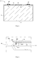
- the secondary battery includes a cap plate assembly 1, an electrode assembly 2, a case 3 and a current collecting assembly 4.
- the electrode assembly 2 is a core member used for the secondary battery to realize charge and discharge functions.
- the electrode assembly 2 includes a positive electrode plate, a negative electrode plate and a separator.
- the separator separates the positive electrode plate from the negative electrode plate.
- the positive electrode plate includes a positive electrode current collector and a positive electrode active material layer coated on a surface of the positive electrode current collector.
- the positive electrode current collector may be an aluminum foil, and the positive electrode active material layer includes a ternary material, lithium manganate or lithium iron phosphate.
- the negative electrode plate includes a negative electrode current collector and a negative electrode active material layer coated on a surface of the negative electrode current collector.
- the negative electrode current collector may be a copper foil and the negative electrode active material layer includes graphite or silicon.
- the electrode assembly 2 may be of a winding structure. Specifically, there is one positive electrode plate and one negative electrode plate respectively, and the positive electrode plate and the negative electrode plate are of a strip structure. The positive electrode plate, the separator and the negative electrode plate are stacked in sequence and wound two or more circles to form the electrode assembly 2. During preparation of the electrode assembly 2, the electrode assembly 2 may be firstly wound into a hollow cylindrical structure and then flattened to a flat shape.
- the electrode assembly 2 may also be of a stacked structure. Specifically, there are a plurality of positive electrode plates and a plurality of negative electrode plates. The plurality of positive electrode plates and the plurality of negative electrode plates are stacked alternately and the separator separates the positive electrode plate from the negative electrode plate.
- the case 3 may be of hexahedral shape or another shape.
- the interior of the case 3 is formed into a receiving chamber to receive the electrode assembly 2 and electrolyte.
- An opening is formed at an end of the case 3 and the electrode assembly 2 may be placed into the receiving chamber through the opening.
- the case 3 may be made of a conductive metal material.
- the case 3 is made of aluminum or an aluminum alloy.
- the cap plate assembly 1 includes a cap plate 11, an electrode terminal 15 and an insulator 16.
- the cap plate is disposed at the case 3 and covers the opening of the case 3. Therefore, the electrode assembly 2 is sealed in the case 3.
- the cap plate 11 may be a metal plate and may be connected to the case 3 by welding.
- the cap plate 11 is provided with two penetrating terminal holes.
- Two electrode terminals 15 are disposed at an upper side of the cap plate 11, that is, at a side of the cap plate 11 away from the electrode assembly 2. Each electrode terminal 15 covers a corresponding terminal hole.
- a sealing ring is disposed between the cap plate 11 and the electrode terminal 15. The terminal holes may be sealed up by compressing the sealing ring.
- the insulator 16 is disposed at an inner side of the cap plate 11 so that the electrode assembly 2 and the cap plate 11 are separated, thereby reducing the risk of short circuit.
- One current collecting assembly 4 is connected to one electrode terminal 15 and the positive electrode plate of the electrode assembly 2; the other current collecting assembly 4 is connected to another electrode terminal 15 and the negative electrode plate of the electrode assembly 2.
- the cap plate assembly 1 of the present disclosure may further include an explosion-proof sheet 12.
- the cap plate 11 is disposed with a through hole 111
- the explosion-proof sheet 12 is disposed at the cap plate 11 and seals the through hole 111.
- the explosion-proof sheet 12 can cover the through hole 111 and separate an internal space of the secondary battery from an outside space, thereby preventing the electrolyte in the case 3 from leaking through the through hole 111.
- the explosion-proof sheet has a weak region 121a. Compared with other region of the explosion-proof sheet, the weak region 121a has a low strength and thus easy to break. In the present disclosure, the weak region 121a may be of ring shape.
- the strength of the weak region 121a may be reduced by decreasing the thickness of the weak region 121a. That is, a thickness of the weak region 121a is smaller than a thickness of other region of the explosion-proof sheet 12.
- the electrode assembly 2 may release gas.
- the gas pressure in the secondary battery will gradually increase.
- the explosion-proof sheet 12 will deform under the action of the gas pressure.
- the explosion-proof sheet 12 will break at the weak region 121a.
- the high pressure gas breaks through the explosion-proof sheet 12 and is released to outside of the secondary battery, thereby releasing pressure and reducing explosion risk.
- the explosion-proof sheet 12 includes a main body 121 and a connecting part 122.
- the main body 121 covers the through hole 111.
- the weak region 121a is formed at the main body 121 and the thickness of the weak region 121a is smaller than the thickness of other region of the main body 121.
- the weak region 121a is formed by pressing a notch 121b on the main body 121.
- the connecting part 122 surrounds the outer side of the main body 121, the connecting part 122 is connected to the cap plate 11 and a connecting region between the connecting part 122 and the cap plate 11 is of ring shape. In this way, sealing is achieved.
- the explosion-proof sheet of the secondary battery can open in time to release pressure and reduce temperature.
- the heat of the nail-penetrated secondary battery may be quickly diffused to an adjacent secondary battery.
- the internal temperature of the adjacent secondary battery is quickly increased due to heat diffusion of other secondary battery and its internal short circuit.
- the cap plate assembly 1 of the present disclosure may further include a fixing piece 13.
- the fixing piece 13 connects the cap plate 11 and the explosion-proof sheet 12. Specifically, the fixing piece 13 is connected to the connecting part 122 of the explosion-proof sheet 12. The melting point of the fixing piece 13 is lower than the melting point of the cap plate 11 and the melting point of the explosion-proof sheet 12. Normally, the fixing piece is in a solid state and connects with the cap plate 11 and the connecting part 122 to ensure connecting strength between the cap plate 11 and the connecting part 122, thereby preventing the connecting part 122 from disconnecting the cap plate 11.
- the fixing piece When a secondary battery has a quickly increasing temperature due to heat diffusion of another secondary battery and/or its internal short circuit, the fixing piece may be molten at a high temperature. During the melting process, the connecting strength between the cap plate 11 and the connecting part 122 may be reduced.
- the explosion-proof sheet 12 is configured as follows: when the fixing piece 13 does not melt, the weak region 121a will break in a case that the internal gas pressure in the secondary battery exceeds a value required for breakage of the weak region 121a.
- the statement that "the fixing piece 13 does not melt” refers to that the fixing piece 13 is entirely in a solid state. In case of no melting, the fixing piece 13 can effectively connect the cap plate 11 and the connecting part 122. Thus, the connecting part 122 will not separate from the cap plate 11.
- the gas pressure required for breakage of the weak region 121a may be set to 0.5MPa - 10MPa. The specific value may be set according to the model of the secondary battery.
- the explosion-proof sheet 12 is further configured as follows: when the fixing piece 13 melts, the explosion-proof sheet 12 can at least partially separate from the cap plate 11 in a case that the internal gas pressure in the secondary battery is lower than the value required for breakage of the weak region 121a.
- the statement "the fixing piece 13 melts” refers to that the fixing piece 13 at least partially melts into liquid.
- the connecting strength between the cap plate 11 and the connecting part 122 is reduced. Therefore, the connecting part 122 can at least partially separate from the cap plate 11 in a case that the internal gas pressure of the secondary battery is lower than the gas pressure required for breakage of the weak region 121a.
- the electrode assembly 2 of the secondary battery will release heat and gas.
- the internal gas pressure of the secondary battery can reach a value required for breakage of the weak region 121a.
- the explosion-proof sheet 12 breaks at the weak region 121a.
- the high pressure gas breaks through the explosion-proof sheet 12 and is released to outside of the secondary battery, thereby releasing pressure and reducing temperature, and further reducing safety risk.
- the secondary battery may have a quickly increasing temperature due to heat diffusion of the another secondary battery and its internal short circuit.
- the fixing piece 13 melts.
- the gas may still separate the connecting part 122 from the cap plate 11. In this way, the gas is discharged to outside of the secondary battery, thereby releasing pressure, reducing temperature and lowering safety risk.
- the fixing piece 13 with a low melting point is connected with the cap plate and the explosion-proof sheet, and moreover the weak region is disposed at the explosion-proof sheet, thus the gas pressure and temperature inside the secondary battery are both taken into consideration, the explosion-proof sheet may be opened in time to achieve pressure release and temperature decrease, thereby reducing explosion risk and improving safety performance.
- the fixing piece 13 may be firstly placed between the cap plate 11 and the explosion-proof sheet 12, and then the fixing piece 13 is heated. After the fixing piece 13 melts, the fixing piece 13 is connected with the cap plate 11 and the explosion-proof sheet 12. After solidification, the fixing piece 13 may connect the cap plate 11 and the explosion-proof sheet 12 to ensure the connecting strength between the cap plate 11 and the explosion-proof sheet 12.
- the material of the fixing piece 13 is alloy.
- the electrode assembly 2 may also releases heat, resulting in temperature increase of the secondary battery. If the melting point of the alloy is excessively low, the fixing piece 13 may melt during a normal use of the secondary battery, so that the connecting strength between the cap plate 11 and the explosion-proof sheet 12 is insufficient. Further, when the secondary battery vibrates, the explosion-proof sheet 12 may separate from the cap plate 11, resulting in leakage of electrolyte and safety accident.
- the temperature of the alloy shall not be lower than 50°C.
- the melting point of the alloy is excessively high, when the secondary battery reaches a critical temperature of an explosion, the alloy may not melt and the explosion-proof sheet 12 also may not separate from the cap plate 11, resulting in safety accident. Therefore, in an example, the melting point of the alloy shall not be higher than 300°C.
- the alloy is a tin-bismuth alloy or a tin-copper-silver alloy.
- the tin-bismuth alloy or the tin-copper-silver alloy may be better connected with the cap plate 11 and the explosion-proof sheet 12 both made of aluminum, thereby increasing connecting strength.
- the connecting strength between the fixing piece 13 and the connecting part 122 is larger than the breaking strength of the weak region 121a.
- the breaking strength of the weak region 121a refers to a gas pressure critical value enabling the explosion-proof sheet 12 to break at the weak region 121a on a precondition that the fixing piece 13 does not melt.
- the gas pressure critical value may be 0.5MPa - 10MPa.
- the connecting strength between the fixing piece 13 and the explosion-proof sheet 12 refers to a gas pressure critical value enabling the explosion-proof sheet 12 to separate from the fixing piece 13 on a precondition that the fixing piece 13 does not melt.
- the explosion-proof sheet 12 may separate from the fixing piece 13 and the cap plate 11 before the internal gas pressure of the secondary battery reaches the breaking strength of the weak region 121a, so that the explosion-proof sheet 12 cannot open in a case that the secondary battery reaches a set gas pressure value. Further, compared with control of consistency of thickness of the weak region 121a, it is more difficult to control consistency of connecting strength between the fixing piece 13 and the explosion-proof sheet 12.
- the connecting strength between the fixing piece 13 and the cap plate 11 is larger than the breaking strength of the weak region 121a.
- the cap plate assembly 1 of the secondary battery according to the present disclosure will be detailed below in combination with different examples.
- the cap plate 11 has a first surface 112 and a second surface 113 disposed oppositely in a thickness direction Z.
- the first surface 112 is an outer surface of the cap plate 11 away from the electrode assembly 2 and the second surface 113 is an inner surface of the cap plate 11 close to the electrode assembly 2.
- the through hole 111 penetrates through the first surface 112 and the second surface 113.
- the explosion-proof sheet 12 is located at a side of the cap plate 11 away from the electrode assembly 2, and the fixing piece 13 is located between the first surface 112 of the cap plate 11 and the explosion-proof sheet 12.
- the cap plate 11 may support the explosion-proof sheet 12 from a lower side. In this case, when the fixing piece 13 melts, the explosion-proof sheet 12 is prevented from falling into the secondary battery, thereby reducing a potential safety hazard.
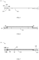
- the cap plate 11 according to a second example further has a first groove 114.
- the first groove 114 concaves toward the second surface 113 from the first surface 112.
- the first groove 114 is of ring shape, surrounds the periphery of the through hole 111 and communicates with the through hole 111.
- the fixing piece 13 is at least partially received in the first groove 114. Further, the fixing piece 13 is located between the explosion-proof sheet 12 and a bottom wall 114a of the first groove 114. In an example, the fixing piece 13 is completely received in the first groove 114.
- space occupied by the fixing piece 13 in the thickness direction Z may be reduced by disposing the first groove 114 in the second example.
- the explosion-proof sheet 12 is at least partially located in the first groove 114. In an example, the explosion-proof sheet 12 is completely received in the first groove 114. In this way, the space occupied by the explosion-proof sheet 12 in the thickness direction is saved.
- the cap plate assembly 1 further includes a protection sheet 14.
- the protection sheet 14 is located at a side of the explosion-proof sheet 12 away from the electrode assembly 2.
- the protection sheet 14 may also be fixed at the first surface 112 of the cap plate 11 and cover the first groove 114.
- the protection sheet 14 may protect the explosion-proof sheet 12 from being damaged by external impurities.
- the protection sheet is a film sheet with less strength. When the explosion-proof sheet 12 opens, the protection sheet 14 is easily broken through by the high temperature gas and thus will not block release of the high temperature gas.
- a gap is disposed between the explosion-proof sheet 12 and the protection sheet 14.
- the explosion-proof sheet 12 deforms under the action of gas pressure. If the explosion-proof sheet 12 is in direct contact with the protection sheet 14, the protection sheet 14 may limit the deformation of the explosion-proof sheet 12, thereby hindering breakage of the weak region 121a.
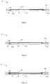
- the cap plate 11 according to a third example further includes a stopping part 115.
- the stopping part 115 extends toward the explosion-proof sheet 12 from the bottom wall 114a of the first groove 114.
- the stopping part 115 surrounds the periphery of the through hole 111.
- the fixing piece 13 is at least partially located at a side of the stopping part away from the through hole 111. That is, the fixing piece 13 is at least partially located between the stopping part 115 and a side wall 114b of the first groove 114.
- the stopping part 115 may block flow of the metal liquid, thereby reducing the metal liquid flowing to the electrode assembly 2 and lowering the safety risk.
- the explosion-proof sheet 12 is at least partially located in the first groove 114 to reduce space occupied by the explosion-proof sheet 12 in the thickness direction Z. In an example, the explosion-proof sheet 12 is completely located in the first groove 114.
- the cap plate 11 according to a fourth example further has a second groove 116.
- the second groove 116 concaves toward the second surface 113 from the first surface 112 and the second groove 116 surrounds the periphery of the first groove 114.
- a depth of the second groove 116 is smaller than a depth of the first groove 114.
- a step may be formed at the cap plate 11 by disposing the first groove 114 and the second groove 116.
- the step may facilite location and installation of the explosion-proof sheet 12.
- the fixing piece 13 includes a first part 131 and a second part 132.
- the first part 131 is located at a side of the stopping part 115 away from the through hole 111, and the second part 132 extends from an edge of the first part 131 close to the through hole 111, and is located between the stopping part 115 and the explosion-proof sheet 12.
- connecting area between the fixing piece 13 and the connecting part 122 is increased by disposing the second part 132 in the fifth example, so that sealing performance between the fixing piece 13 and the explosion-proof sheet 12 is improved.
- the fixing piece has a receiving groove 133.
- the receiving groove 133 concaves from an inner wall 134 of the fixing piece 13 close to the through hole 111.
- the connecting part 122 of the explosion-proof sheet 12 is inserted into the receiving groove 133 of the fixing piece 13 and connected with the fixing piece 13.
Landscapes
- Chemical & Material Sciences (AREA)
- Chemical Kinetics & Catalysis (AREA)
- Electrochemistry (AREA)
- General Chemical & Material Sciences (AREA)
- Inorganic Chemistry (AREA)
- Engineering & Computer Science (AREA)
- Materials Engineering (AREA)
- Manufacturing & Machinery (AREA)
- Gas Exhaust Devices For Batteries (AREA)
Applications Claiming Priority (1)
| Application Number | Priority Date | Filing Date | Title |
|---|---|---|---|
| CN201910696198.4A CN110400895B (zh) | 2019-07-30 | 2019-07-30 | 电池模组、二次电池及其顶盖组件 |
Publications (2)
| Publication Number | Publication Date |
|---|---|
| EP3772120A1 true EP3772120A1 (de) | 2021-02-03 |
| EP3772120B1 EP3772120B1 (de) | 2021-07-28 |
Family
ID=68326600
Family Applications (1)
| Application Number | Title | Priority Date | Filing Date |
|---|---|---|---|
| EP19217502.4A Active EP3772120B1 (de) | 2019-07-30 | 2019-12-18 | Batteriemodul, sekundärbatterie und kappenplattenanordnung dafür |
Country Status (4)
| Country | Link |
|---|---|
| US (1) | US20210036285A1 (de) |
| EP (1) | EP3772120B1 (de) |
| CN (1) | CN110400895B (de) |
| WO (1) | WO2021017905A1 (de) |
Cited By (6)
| Publication number | Priority date | Publication date | Assignee | Title |
|---|---|---|---|---|
| CN113178907A (zh) * | 2021-04-21 | 2021-07-27 | 深圳市驰普科达科技有限公司 | 一种工业电池用智能充电设备及其充电方法 |
| CN115528378A (zh) * | 2022-09-30 | 2022-12-27 | 厦门海辰储能科技股份有限公司 | 下塑胶、顶盖组件、电池、电池模组及用电设备 |
| EP4120448A4 (de) * | 2021-06-01 | 2023-01-18 | Contemporary Amperex Technology Co., Limited | Endabdeckungsanordnung, batteriezelle, batterie und elektrische vorrichtung |
| EP4123798A4 (de) * | 2021-06-01 | 2023-05-31 | Contemporary Amperex Technology Co., Limited | Endabdeckung, batteriezelle, batterie, und vorrichtung und verfahren zum herstellen einer batteriezelle |
| EP4228071A1 (de) * | 2022-02-10 | 2023-08-16 | CALB Co., Ltd. | Batteriebehälter und batteriesatz |
| EP4379933A4 (de) * | 2022-04-24 | 2024-10-23 | Contemporary Amperex Technology (Hong Kong) Limited | Endkappenanordnung, batterie und elektrische vorrichtung |
Families Citing this family (36)
| Publication number | Priority date | Publication date | Assignee | Title |
|---|---|---|---|---|
| CN110400895B (zh) * | 2019-07-30 | 2021-03-09 | 宁德时代新能源科技股份有限公司 | 电池模组、二次电池及其顶盖组件 |
| DE102019220391A1 (de) * | 2019-12-20 | 2021-06-24 | Volkswagen Aktiengesellschaft | Notentgasungsanordnung für die Notentgasung eines Akkumulators eines elektrisch angetriebenen Kraftfahrzeugs |
| CN113146148A (zh) * | 2020-01-21 | 2021-07-23 | 常州微宙电子科技有限公司 | 防爆壳体及其刻槽方法和具有其的电池 |
| CN111564651B (zh) * | 2020-05-12 | 2024-01-19 | 路华置富电子(深圳)有限公司 | 叠绕电芯电池 |
| CN111525072A (zh) * | 2020-05-28 | 2020-08-11 | 瑞声科技(南京)有限公司 | 纽扣电池 |
| CN111525071B (zh) * | 2020-05-28 | 2021-09-24 | 瑞声科技(南京)有限公司 | 纽扣电池及电子设备 |
| CN111525070B (zh) * | 2020-05-28 | 2021-09-24 | 瑞声科技(南京)有限公司 | 纽扣电池及电子设备 |
| HUE067215T2 (hu) | 2020-07-10 | 2024-10-28 | Contemporary Amperex Technology Hong Kong Ltd | Akkumulátor, az elõállítására szolgáló berendezés és eljárás, valamint készülék |
| CN112234309A (zh) * | 2020-11-19 | 2021-01-15 | 常州瑞德丰精密技术有限公司 | 二次电池顶盖组件以及二次电池 |
| EP4254613A4 (de) * | 2020-11-26 | 2024-10-09 | Ningde Amperex Technology Limited | Elektrochemische vorrichtung und elektronische vorrichtung |
| JP2022113312A (ja) * | 2021-01-25 | 2022-08-04 | プライムプラネットエナジー&ソリューションズ株式会社 | ガス排出弁を備えた封口板及びそれを用いた二次電池 |
| CN112886110B (zh) * | 2021-03-09 | 2025-07-15 | 江苏瑞德丰精密技术股份有限公司 | 一种顶盖组件以及动力电池 |
| CN114018511A (zh) * | 2021-11-04 | 2022-02-08 | 中船澄西扬州船舶有限公司 | 一种舱室气密性检测工装 |
| CN114142188B (zh) * | 2021-11-30 | 2024-11-05 | 宁德新能源科技有限公司 | 电化学装置及用电设备 |
| DE102021214245A1 (de) | 2021-12-13 | 2023-06-15 | Audi Aktiengesellschaft | Abdeckelement in Sandwichbauweise mit aufschmelzbarer Zwischenlage für ein Batteriegehäuse, Batteriegehäuse und Kraftfahrzeug |
| CN117413422A (zh) * | 2022-01-27 | 2024-01-16 | 宁德时代新能源科技股份有限公司 | 端盖组件、电池单体、电池以及用电装置 |
| CN114643430B (zh) * | 2022-04-27 | 2024-05-17 | 深圳市大德激光技术有限公司 | 一种动力电池防爆片激光精雕夹具装置 |
| CN217114584U (zh) * | 2022-05-16 | 2022-08-02 | 宁德时代新能源科技股份有限公司 | 端盖组件、电池单体、电池及用电装置 |
| CN115832604B (zh) * | 2022-08-12 | 2026-03-03 | 江苏时代新能源科技有限公司 | 电池单体、电池及用电设备 |
| WO2024040530A1 (zh) * | 2022-08-25 | 2024-02-29 | 宁德时代新能源科技股份有限公司 | 电池单体、电池及用电设备 |
| CN115275502A (zh) * | 2022-08-31 | 2022-11-01 | 宁德新能源科技有限公司 | 电化学装置及用电设备 |
| CN115832394A (zh) * | 2022-11-07 | 2023-03-21 | 深圳市比克动力电池有限公司 | 卷芯、电池、卷芯的制造方法及电池的制造方法 |
| CN115882125B (zh) * | 2022-11-17 | 2024-09-06 | 宁德时代新能源科技股份有限公司 | 电池单体、电池及用电设备 |
| CN116274558A (zh) * | 2023-01-09 | 2023-06-23 | 东莞领益精密制造科技有限公司 | 防爆片压合设备、防爆片的生产线及加工方法 |
| CN116787070A (zh) * | 2023-02-07 | 2023-09-22 | 万向一二三股份公司 | 一种在电池壳体上加工防爆片焊接孔的方法 |
| CN116666887A (zh) * | 2023-05-31 | 2023-08-29 | 宁德时代新能源科技股份有限公司 | 电池单体、电池及用电设备 |
| CN119231083A (zh) * | 2023-06-29 | 2024-12-31 | 宁德时代新能源科技股份有限公司 | 电池单体、电池以及用电装置 |
| EP4507101A4 (de) * | 2023-07-12 | 2025-12-17 | Eve Energy Co Ltd | Batteriezelle und batteriepack |
| CN117080638B (zh) * | 2023-10-12 | 2023-12-26 | 厦门海辰储能科技股份有限公司 | 端盖组件、储能装置和用电设备 |
| CN117080671B (zh) * | 2023-10-16 | 2024-01-26 | 厦门海辰储能科技股份有限公司 | 顶盖组件、电池、储能装置及用电装置 |
| KR20250066680A (ko) * | 2023-11-07 | 2025-05-14 | 에스케이온 주식회사 | 배터리모듈 |
| WO2025107153A1 (zh) * | 2023-11-21 | 2025-05-30 | 宁德时代新能源科技股份有限公司 | 电池单体、电池以及用电装置 |
| CN222355249U (zh) * | 2023-12-14 | 2025-01-14 | 惠州亿纬锂能股份有限公司 | 盖帽组件、电池单体及电池 |
| CN118507976A (zh) * | 2024-02-22 | 2024-08-16 | 比亚迪股份有限公司 | 防爆阀、盖板组件、电芯、电池包以及用电系统 |
| CN118507975A (zh) * | 2024-02-22 | 2024-08-16 | 比亚迪股份有限公司 | 防爆阀、盖板组件、电芯、电池包以及用电系统 |
| CN121238190A (zh) * | 2024-06-27 | 2025-12-30 | 宁德时代新能源科技股份有限公司 | 电池单体、电池、储能设备及用电设备 |
Citations (4)
| Publication number | Priority date | Publication date | Assignee | Title |
|---|---|---|---|---|
| EP0948065A1 (de) * | 1998-03-30 | 1999-10-06 | Renata AG | Sicherheitsentluftüng für Akkumulator oder Batterie |
| EP1821355A2 (de) * | 2006-01-24 | 2007-08-22 | Toyota Jidosha Kabushiki Kaisha | Batterie und Verfahren zum Montieren der Batterie |
| DE102013210292A1 (de) * | 2013-06-04 | 2014-12-04 | Robert Bosch Gmbh | Sicherheitsventil zum Schutz einer galvanischen Zelle vor schädigendem Überdruck sowie Zellgehäusedeckel und galvanische Zelle mit Sicherheitsventil |
| CN204632837U (zh) * | 2015-04-27 | 2015-09-09 | 迪吉亚节能科技股份有限公司 | 锂电池芯泄压结构 |
Family Cites Families (13)
| Publication number | Priority date | Publication date | Assignee | Title |
|---|---|---|---|---|
| JP2000231912A (ja) * | 1999-02-15 | 2000-08-22 | Toyota Central Res & Dev Lab Inc | 二次電池の安全弁装置 |
| JP4589596B2 (ja) * | 2002-03-22 | 2010-12-01 | パナソニック株式会社 | 電池パック |
| US6887618B2 (en) * | 2002-08-09 | 2005-05-03 | The Gillette Company | Electrochemical cell with flat casing and vent |
| CN1983674A (zh) * | 2005-12-13 | 2007-06-20 | 中国电子科技集团公司第十八研究所 | 一种锂系列电池防爆装置 |
| KR100908912B1 (ko) * | 2008-06-03 | 2009-07-23 | (주) 파워옵틱스 | 안전 배기 조립체, 이의 제조 방법 및 이를 구비한 전기장치 |
| CN203445174U (zh) * | 2013-08-29 | 2014-02-19 | 天津中聚新能源科技有限公司 | 电池防爆结构及包括其的电池 |
| CN105470431A (zh) * | 2014-09-12 | 2016-04-06 | 宁德时代新能源科技股份有限公司 | 电池及其防爆装置 |
| WO2018003761A1 (ja) * | 2016-06-29 | 2018-01-04 | 三洋電機株式会社 | 二次電池 |
| CN206040781U (zh) * | 2016-07-29 | 2017-03-22 | 比亚迪股份有限公司 | 一种防爆阀、盖板组件及电池 |
| CN108428820B (zh) * | 2017-02-14 | 2021-07-30 | 宁德时代新能源科技股份有限公司 | 动力电池顶盖结构及动力电池 |
| CN207454851U (zh) * | 2017-07-27 | 2018-06-05 | 惠州市沃瑞科技有限公司 | 一种应用于新能源汽车上带金属爆破片的防爆透气阀 |
| CN209880668U (zh) * | 2019-07-25 | 2019-12-31 | 宁德时代新能源科技股份有限公司 | 顶盖组件及二次电池 |
| CN110400895B (zh) * | 2019-07-30 | 2021-03-09 | 宁德时代新能源科技股份有限公司 | 电池模组、二次电池及其顶盖组件 |
-
2019
- 2019-07-30 CN CN201910696198.4A patent/CN110400895B/zh active Active
- 2019-12-18 EP EP19217502.4A patent/EP3772120B1/de active Active
- 2019-12-20 US US16/722,251 patent/US20210036285A1/en not_active Abandoned
-
2020
- 2020-07-17 WO PCT/CN2020/102831 patent/WO2021017905A1/zh not_active Ceased
Patent Citations (4)
| Publication number | Priority date | Publication date | Assignee | Title |
|---|---|---|---|---|
| EP0948065A1 (de) * | 1998-03-30 | 1999-10-06 | Renata AG | Sicherheitsentluftüng für Akkumulator oder Batterie |
| EP1821355A2 (de) * | 2006-01-24 | 2007-08-22 | Toyota Jidosha Kabushiki Kaisha | Batterie und Verfahren zum Montieren der Batterie |
| DE102013210292A1 (de) * | 2013-06-04 | 2014-12-04 | Robert Bosch Gmbh | Sicherheitsventil zum Schutz einer galvanischen Zelle vor schädigendem Überdruck sowie Zellgehäusedeckel und galvanische Zelle mit Sicherheitsventil |
| CN204632837U (zh) * | 2015-04-27 | 2015-09-09 | 迪吉亚节能科技股份有限公司 | 锂电池芯泄压结构 |
Cited By (9)
| Publication number | Priority date | Publication date | Assignee | Title |
|---|---|---|---|---|
| CN113178907A (zh) * | 2021-04-21 | 2021-07-27 | 深圳市驰普科达科技有限公司 | 一种工业电池用智能充电设备及其充电方法 |
| EP4120448A4 (de) * | 2021-06-01 | 2023-01-18 | Contemporary Amperex Technology Co., Limited | Endabdeckungsanordnung, batteriezelle, batterie und elektrische vorrichtung |
| CN116134670A (zh) * | 2021-06-01 | 2023-05-16 | 宁德时代新能源科技股份有限公司 | 端盖组件、电池单体、电池以及用电装置 |
| EP4123798A4 (de) * | 2021-06-01 | 2023-05-31 | Contemporary Amperex Technology Co., Limited | Endabdeckung, batteriezelle, batterie, und vorrichtung und verfahren zum herstellen einer batteriezelle |
| US12368209B2 (en) | 2021-06-01 | 2025-07-22 | Contemporary Amperex Technology (Hong Kong) Limited | End cover assembly, battery cell, battery and electric device |
| EP4228071A1 (de) * | 2022-02-10 | 2023-08-16 | CALB Co., Ltd. | Batteriebehälter und batteriesatz |
| EP4379933A4 (de) * | 2022-04-24 | 2024-10-23 | Contemporary Amperex Technology (Hong Kong) Limited | Endkappenanordnung, batterie und elektrische vorrichtung |
| CN115528378A (zh) * | 2022-09-30 | 2022-12-27 | 厦门海辰储能科技股份有限公司 | 下塑胶、顶盖组件、电池、电池模组及用电设备 |
| CN115528378B (zh) * | 2022-09-30 | 2024-01-23 | 厦门海辰储能科技股份有限公司 | 下塑胶、顶盖组件、电池、电池模组及用电设备 |
Also Published As
| Publication number | Publication date |
|---|---|
| WO2021017905A1 (zh) | 2021-02-04 |
| EP3772120B1 (de) | 2021-07-28 |
| CN110400895B (zh) | 2021-03-09 |
| CN110400895A (zh) | 2019-11-01 |
| US20210036285A1 (en) | 2021-02-04 |
Similar Documents
| Publication | Publication Date | Title |
|---|---|---|
| EP3772120B1 (de) | Batteriemodul, sekundärbatterie und kappenplattenanordnung dafür | |
| US11949119B2 (en) | Cover assembly of secondary battery and secondary battery | |
| JP5517974B2 (ja) | 二次電池 | |
| KR101256071B1 (ko) | 이차 전지 | |
| KR100731453B1 (ko) | 원통형 리튬 이차전지 | |
| KR101279994B1 (ko) | 전극리드에 안전부재가 위치한 구조의 캡 어셈블리 및 이를 포함하고 있는 원통형 전지 | |
| EP2772963B1 (de) | Wiederaufladbare Batterie | |
| EP2924763B1 (de) | Sekundärbatterie | |
| EP2892086A1 (de) | Rechteckige sekundärbatterie | |
| KR101772415B1 (ko) | 캡 조립체 및 이를 포함하는 이차 전지 | |
| EP2793295A2 (de) | Wiederaufladbare Batterie | |
| KR20150047417A (ko) | 퓨즈부를 갖는 이차 전지 및 전지 모듈 | |
| CN111384348B (zh) | 二次电池和电池模组 | |
| WO2025103239A1 (zh) | 电化学装置及用电设备 | |
| KR102761907B1 (ko) | 이차 전지 | |
| EP1919010B1 (de) | Akku | |
| EP2775554B1 (de) | Wiederaufladbare Batterie | |
| EP3989356B1 (de) | Batterie, batteriemodul und batteriesatz | |
| CN211907570U (zh) | 极耳结构、电池及电池模组 | |
| CN118867557A (zh) | 电池及电池组 | |
| JP5442072B2 (ja) | 密閉角形電池 | |
| KR102293970B1 (ko) | 바이메탈로 이루어진 전류 차단 부재를 포함하는 캡 어셈블리 | |
| KR100770111B1 (ko) | 원통형 리튬 이차전지 | |
| KR100521477B1 (ko) | 이차 전지 | |
| KR20140082270A (ko) | 이차 전지 및 이를 포함하는 배터리 팩 |
Legal Events
| Date | Code | Title | Description |
|---|---|---|---|
| PUAI | Public reference made under article 153(3) epc to a published international application that has entered the european phase |
Free format text: ORIGINAL CODE: 0009012 |
|
| STAA | Information on the status of an ep patent application or granted ep patent |
Free format text: STATUS: REQUEST FOR EXAMINATION WAS MADE |
|
| 17P | Request for examination filed |
Effective date: 20191218 |
|
| AK | Designated contracting states |
Kind code of ref document: A1 Designated state(s): AL AT BE BG CH CY CZ DE DK EE ES FI FR GB GR HR HU IE IS IT LI LT LU LV MC MK MT NL NO PL PT RO RS SE SI SK SM TR |
|
| AX | Request for extension of the european patent |
Extension state: BA ME |
|
| REG | Reference to a national code |
Ref country code: DE Ref legal event code: R079 Ref document number: 602019006447 Country of ref document: DE Free format text: PREVIOUS MAIN CLASS: H01M0002040000 Ipc: H01M0050147000 |
|
| GRAP | Despatch of communication of intention to grant a patent |
Free format text: ORIGINAL CODE: EPIDOSNIGR1 |
|
| STAA | Information on the status of an ep patent application or granted ep patent |
Free format text: STATUS: GRANT OF PATENT IS INTENDED |
|
| RIC1 | Information provided on ipc code assigned before grant |
Ipc: H01M 50/147 20210101AFI20210226BHEP |
|
| INTG | Intention to grant announced |
Effective date: 20210329 |
|
| GRAS | Grant fee paid |
Free format text: ORIGINAL CODE: EPIDOSNIGR3 |
|
| GRAA | (expected) grant |
Free format text: ORIGINAL CODE: 0009210 |
|
| STAA | Information on the status of an ep patent application or granted ep patent |
Free format text: STATUS: THE PATENT HAS BEEN GRANTED |
|
| AK | Designated contracting states |
Kind code of ref document: B1 Designated state(s): AL AT BE BG CH CY CZ DE DK EE ES FI FR GB GR HR HU IE IS IT LI LT LU LV MC MK MT NL NO PL PT RO RS SE SI SK SM TR |
|
| REG | Reference to a national code |
Ref country code: GB Ref legal event code: FG4D |
|
| REG | Reference to a national code |
Ref country code: CH Ref legal event code: EP |
|
| REG | Reference to a national code |
Ref country code: AT Ref legal event code: REF Ref document number: 1415525 Country of ref document: AT Kind code of ref document: T Effective date: 20210815 |
|
| REG | Reference to a national code |
Ref country code: IE Ref legal event code: FG4D |
|
| REG | Reference to a national code |
Ref country code: DE Ref legal event code: R096 Ref document number: 602019006447 Country of ref document: DE |
|
| REG | Reference to a national code |
Ref country code: LT Ref legal event code: MG9D |
|
| REG | Reference to a national code |
Ref country code: NL Ref legal event code: MP Effective date: 20210728 |
|
| REG | Reference to a national code |
Ref country code: AT Ref legal event code: MK05 Ref document number: 1415525 Country of ref document: AT Kind code of ref document: T Effective date: 20210728 |
|
| PG25 | Lapsed in a contracting state [announced via postgrant information from national office to epo] |
Ref country code: SE Free format text: LAPSE BECAUSE OF FAILURE TO SUBMIT A TRANSLATION OF THE DESCRIPTION OR TO PAY THE FEE WITHIN THE PRESCRIBED TIME-LIMIT Effective date: 20210728 Ref country code: RS Free format text: LAPSE BECAUSE OF FAILURE TO SUBMIT A TRANSLATION OF THE DESCRIPTION OR TO PAY THE FEE WITHIN THE PRESCRIBED TIME-LIMIT Effective date: 20210728 Ref country code: ES Free format text: LAPSE BECAUSE OF FAILURE TO SUBMIT A TRANSLATION OF THE DESCRIPTION OR TO PAY THE FEE WITHIN THE PRESCRIBED TIME-LIMIT Effective date: 20210728 Ref country code: PT Free format text: LAPSE BECAUSE OF FAILURE TO SUBMIT A TRANSLATION OF THE DESCRIPTION OR TO PAY THE FEE WITHIN THE PRESCRIBED TIME-LIMIT Effective date: 20211129 Ref country code: NO Free format text: LAPSE BECAUSE OF FAILURE TO SUBMIT A TRANSLATION OF THE DESCRIPTION OR TO PAY THE FEE WITHIN THE PRESCRIBED TIME-LIMIT Effective date: 20211028 Ref country code: NL Free format text: LAPSE BECAUSE OF FAILURE TO SUBMIT A TRANSLATION OF THE DESCRIPTION OR TO PAY THE FEE WITHIN THE PRESCRIBED TIME-LIMIT Effective date: 20210728 Ref country code: FI Free format text: LAPSE BECAUSE OF FAILURE TO SUBMIT A TRANSLATION OF THE DESCRIPTION OR TO PAY THE FEE WITHIN THE PRESCRIBED TIME-LIMIT Effective date: 20210728 Ref country code: HR Free format text: LAPSE BECAUSE OF FAILURE TO SUBMIT A TRANSLATION OF THE DESCRIPTION OR TO PAY THE FEE WITHIN THE PRESCRIBED TIME-LIMIT Effective date: 20210728 Ref country code: BG Free format text: LAPSE BECAUSE OF FAILURE TO SUBMIT A TRANSLATION OF THE DESCRIPTION OR TO PAY THE FEE WITHIN THE PRESCRIBED TIME-LIMIT Effective date: 20211028 Ref country code: AT Free format text: LAPSE BECAUSE OF FAILURE TO SUBMIT A TRANSLATION OF THE DESCRIPTION OR TO PAY THE FEE WITHIN THE PRESCRIBED TIME-LIMIT Effective date: 20210728 Ref country code: LT Free format text: LAPSE BECAUSE OF FAILURE TO SUBMIT A TRANSLATION OF THE DESCRIPTION OR TO PAY THE FEE WITHIN THE PRESCRIBED TIME-LIMIT Effective date: 20210728 |
|
| PG25 | Lapsed in a contracting state [announced via postgrant information from national office to epo] |
Ref country code: PL Free format text: LAPSE BECAUSE OF FAILURE TO SUBMIT A TRANSLATION OF THE DESCRIPTION OR TO PAY THE FEE WITHIN THE PRESCRIBED TIME-LIMIT Effective date: 20210728 Ref country code: LV Free format text: LAPSE BECAUSE OF FAILURE TO SUBMIT A TRANSLATION OF THE DESCRIPTION OR TO PAY THE FEE WITHIN THE PRESCRIBED TIME-LIMIT Effective date: 20210728 Ref country code: GR Free format text: LAPSE BECAUSE OF FAILURE TO SUBMIT A TRANSLATION OF THE DESCRIPTION OR TO PAY THE FEE WITHIN THE PRESCRIBED TIME-LIMIT Effective date: 20211029 |
|
| PG25 | Lapsed in a contracting state [announced via postgrant information from national office to epo] |
Ref country code: DK Free format text: LAPSE BECAUSE OF FAILURE TO SUBMIT A TRANSLATION OF THE DESCRIPTION OR TO PAY THE FEE WITHIN THE PRESCRIBED TIME-LIMIT Effective date: 20210728 |
|
| REG | Reference to a national code |
Ref country code: DE Ref legal event code: R097 Ref document number: 602019006447 Country of ref document: DE |
|
| PG25 | Lapsed in a contracting state [announced via postgrant information from national office to epo] |
Ref country code: SM Free format text: LAPSE BECAUSE OF FAILURE TO SUBMIT A TRANSLATION OF THE DESCRIPTION OR TO PAY THE FEE WITHIN THE PRESCRIBED TIME-LIMIT Effective date: 20210728 Ref country code: SK Free format text: LAPSE BECAUSE OF FAILURE TO SUBMIT A TRANSLATION OF THE DESCRIPTION OR TO PAY THE FEE WITHIN THE PRESCRIBED TIME-LIMIT Effective date: 20210728 Ref country code: RO Free format text: LAPSE BECAUSE OF FAILURE TO SUBMIT A TRANSLATION OF THE DESCRIPTION OR TO PAY THE FEE WITHIN THE PRESCRIBED TIME-LIMIT Effective date: 20210728 Ref country code: EE Free format text: LAPSE BECAUSE OF FAILURE TO SUBMIT A TRANSLATION OF THE DESCRIPTION OR TO PAY THE FEE WITHIN THE PRESCRIBED TIME-LIMIT Effective date: 20210728 Ref country code: CZ Free format text: LAPSE BECAUSE OF FAILURE TO SUBMIT A TRANSLATION OF THE DESCRIPTION OR TO PAY THE FEE WITHIN THE PRESCRIBED TIME-LIMIT Effective date: 20210728 Ref country code: AL Free format text: LAPSE BECAUSE OF FAILURE TO SUBMIT A TRANSLATION OF THE DESCRIPTION OR TO PAY THE FEE WITHIN THE PRESCRIBED TIME-LIMIT Effective date: 20210728 |
|
| PLBE | No opposition filed within time limit |
Free format text: ORIGINAL CODE: 0009261 |
|
| STAA | Information on the status of an ep patent application or granted ep patent |
Free format text: STATUS: NO OPPOSITION FILED WITHIN TIME LIMIT |
|
| 26N | No opposition filed |
Effective date: 20220429 |
|
| PG25 | Lapsed in a contracting state [announced via postgrant information from national office to epo] |
Ref country code: MC Free format text: LAPSE BECAUSE OF FAILURE TO SUBMIT A TRANSLATION OF THE DESCRIPTION OR TO PAY THE FEE WITHIN THE PRESCRIBED TIME-LIMIT Effective date: 20210728 Ref country code: IT Free format text: LAPSE BECAUSE OF FAILURE TO SUBMIT A TRANSLATION OF THE DESCRIPTION OR TO PAY THE FEE WITHIN THE PRESCRIBED TIME-LIMIT Effective date: 20210728 |
|
| REG | Reference to a national code |
Ref country code: BE Ref legal event code: MM Effective date: 20211231 |
|
| PG25 | Lapsed in a contracting state [announced via postgrant information from national office to epo] |
Ref country code: LU Free format text: LAPSE BECAUSE OF NON-PAYMENT OF DUE FEES Effective date: 20211218 Ref country code: IE Free format text: LAPSE BECAUSE OF NON-PAYMENT OF DUE FEES Effective date: 20211218 |
|
| PG25 | Lapsed in a contracting state [announced via postgrant information from national office to epo] |
Ref country code: BE Free format text: LAPSE BECAUSE OF NON-PAYMENT OF DUE FEES Effective date: 20211231 |
|
| P01 | Opt-out of the competence of the unified patent court (upc) registered |
Effective date: 20230516 |
|
| PG25 | Lapsed in a contracting state [announced via postgrant information from national office to epo] |
Ref country code: CY Free format text: LAPSE BECAUSE OF FAILURE TO SUBMIT A TRANSLATION OF THE DESCRIPTION OR TO PAY THE FEE WITHIN THE PRESCRIBED TIME-LIMIT Effective date: 20210728 |
|
| PG25 | Lapsed in a contracting state [announced via postgrant information from national office to epo] |
Ref country code: HU Free format text: LAPSE BECAUSE OF FAILURE TO SUBMIT A TRANSLATION OF THE DESCRIPTION OR TO PAY THE FEE WITHIN THE PRESCRIBED TIME-LIMIT; INVALID AB INITIO Effective date: 20191218 |
|
| REG | Reference to a national code |
Ref country code: CH Ref legal event code: PL |
|
| PG25 | Lapsed in a contracting state [announced via postgrant information from national office to epo] |
Ref country code: LI Free format text: LAPSE BECAUSE OF NON-PAYMENT OF DUE FEES Effective date: 20221231 Ref country code: CH Free format text: LAPSE BECAUSE OF NON-PAYMENT OF DUE FEES Effective date: 20221231 |
|
| PG25 | Lapsed in a contracting state [announced via postgrant information from national office to epo] |
Ref country code: MK Free format text: LAPSE BECAUSE OF FAILURE TO SUBMIT A TRANSLATION OF THE DESCRIPTION OR TO PAY THE FEE WITHIN THE PRESCRIBED TIME-LIMIT Effective date: 20210728 |
|
| PG25 | Lapsed in a contracting state [announced via postgrant information from national office to epo] |
Ref country code: TR Free format text: LAPSE BECAUSE OF FAILURE TO SUBMIT A TRANSLATION OF THE DESCRIPTION OR TO PAY THE FEE WITHIN THE PRESCRIBED TIME-LIMIT Effective date: 20210728 |
|
| REG | Reference to a national code |
Ref country code: DE Ref legal event code: R081 Ref document number: 602019006447 Country of ref document: DE Owner name: CONTEMPORARY AMPEREX TECHNOLOGY (HONG KONG) LI, HK Free format text: FORMER OWNER: CONTEMPORARY AMPEREX TECHNOLOGY CO., LTD., NINGDE CITY, FUJIAN, CN |
|
| REG | Reference to a national code |
Ref country code: GB Ref legal event code: 732E Free format text: REGISTERED BETWEEN 20240815 AND 20240821 |
|
| PG25 | Lapsed in a contracting state [announced via postgrant information from national office to epo] |
Ref country code: MT Free format text: LAPSE BECAUSE OF FAILURE TO SUBMIT A TRANSLATION OF THE DESCRIPTION OR TO PAY THE FEE WITHIN THE PRESCRIBED TIME-LIMIT Effective date: 20210728 |
|
| PGFP | Annual fee paid to national office [announced via postgrant information from national office to epo] |
Ref country code: DE Payment date: 20250930 Year of fee payment: 7 |
|
| PGFP | Annual fee paid to national office [announced via postgrant information from national office to epo] |
Ref country code: GB Payment date: 20251001 Year of fee payment: 7 |
|
| PGFP | Annual fee paid to national office [announced via postgrant information from national office to epo] |
Ref country code: FR Payment date: 20251008 Year of fee payment: 7 |