EP3782928A1 - Stapellageranordnung - Google Patents
Stapellageranordnung Download PDFInfo
- Publication number
- EP3782928A1 EP3782928A1 EP19193379.5A EP19193379A EP3782928A1 EP 3782928 A1 EP3782928 A1 EP 3782928A1 EP 19193379 A EP19193379 A EP 19193379A EP 3782928 A1 EP3782928 A1 EP 3782928A1
- Authority
- EP
- European Patent Office
- Prior art keywords
- storage arrangement
- arrangement according
- stacking storage
- slot
- cross
- Prior art date
- Legal status (The legal status is an assumption and is not a legal conclusion. Google has not performed a legal analysis and makes no representation as to the accuracy of the status listed.)
- Granted
Links
Images


Classifications
-
- B—PERFORMING OPERATIONS; TRANSPORTING
- B65—CONVEYING; PACKING; STORING; HANDLING THIN OR FILAMENTARY MATERIAL
- B65G—TRANSPORT OR STORAGE DEVICES, e.g. CONVEYORS FOR LOADING OR TIPPING, SHOP CONVEYOR SYSTEMS OR PNEUMATIC TUBE CONVEYORS
- B65G1/00—Storing articles, individually or in orderly arrangement, in warehouses or magazines
- B65G1/02—Storage devices
-
- A—HUMAN NECESSITIES
- A47—FURNITURE; DOMESTIC ARTICLES OR APPLIANCES; COFFEE MILLS; SPICE MILLS; SUCTION CLEANERS IN GENERAL
- A47B—TABLES; DESKS; OFFICE FURNITURE; CABINETS; DRAWERS; GENERAL DETAILS OF FURNITURE
- A47B87/00—Sectional furniture, i.e. combinations of complete furniture units, e.g. assemblies of furniture units of the same kind such as linkable cabinets, tables, racks or shelf units
- A47B87/02—Sectional furniture, i.e. combinations of complete furniture units, e.g. assemblies of furniture units of the same kind such as linkable cabinets, tables, racks or shelf units stackable ; stackable and linkable
- A47B87/0207—Stackable racks, trays or shelf units
- A47B87/0261—Independent trays
-
- B—PERFORMING OPERATIONS; TRANSPORTING
- B65—CONVEYING; PACKING; STORING; HANDLING THIN OR FILAMENTARY MATERIAL
- B65G—TRANSPORT OR STORAGE DEVICES, e.g. CONVEYORS FOR LOADING OR TIPPING, SHOP CONVEYOR SYSTEMS OR PNEUMATIC TUBE CONVEYORS
- B65G1/00—Storing articles, individually or in orderly arrangement, in warehouses or magazines
- B65G1/02—Storage devices
- B65G1/04—Storage devices mechanical
- B65G1/0407—Storage devices mechanical using stacker cranes
-
- A—HUMAN NECESSITIES
- A47—FURNITURE; DOMESTIC ARTICLES OR APPLIANCES; COFFEE MILLS; SPICE MILLS; SUCTION CLEANERS IN GENERAL
- A47B—TABLES; DESKS; OFFICE FURNITURE; CABINETS; DRAWERS; GENERAL DETAILS OF FURNITURE
- A47B87/00—Sectional furniture, i.e. combinations of complete furniture units, e.g. assemblies of furniture units of the same kind such as linkable cabinets, tables, racks or shelf units
- A47B87/02—Sectional furniture, i.e. combinations of complete furniture units, e.g. assemblies of furniture units of the same kind such as linkable cabinets, tables, racks or shelf units stackable ; stackable and linkable
- A47B87/0207—Stackable racks, trays or shelf units
- A47B87/0246—Shelves stackable by means of separate vertical distance-holders therebetween
-
- B—PERFORMING OPERATIONS; TRANSPORTING
- B65—CONVEYING; PACKING; STORING; HANDLING THIN OR FILAMENTARY MATERIAL
- B65G—TRANSPORT OR STORAGE DEVICES, e.g. CONVEYORS FOR LOADING OR TIPPING, SHOP CONVEYOR SYSTEMS OR PNEUMATIC TUBE CONVEYORS
- B65G1/00—Storing articles, individually or in orderly arrangement, in warehouses or magazines
- B65G1/02—Storage devices
- B65G1/04—Storage devices mechanical
- B65G1/0471—Storage devices mechanical with access from beneath
Definitions
- the present invention relates to a stack storage arrangement for containers having a plurality of uprights connected together by cross connectors.
- Such a stacking storage arrangement is for example from DE 42 03 823 C2 known.
- containers can be stored in the form of stacks, i.e. several containers are arranged one above the other in the direction of gravity. Such stacks can be arranged relatively closely adjacent, so that an available installation space can be used with a high degree of utilization.
- the stands can be arranged at corners of container receiving spaces.
- the cross connectors serve to give the entire arrangement a certain mechanical stability.
- the containers can be placed on top of the respective stack and removed from there, or the containers can be attached to the stack from below and removed from there.
- the stands can be used to support a driving surface on which operating devices can be moved, with which the containers can be removed from the stacking storage arrangement.
- the uprights are used, for example, to support a top cover in order to be able to close off the stacking storage arrangement.
- the invention is based on the object of keeping the effort involved in building a stacking storage arrangement small.
- this object is achieved in that at least one transverse connector is connected to uprights via connection elements is, each of which rests on a contact surface of a stand, and the contact surface has a slot in which at least one screw protruding through the connecting element is screwed.
- connection element can be moved in the direction of the slot relative to the respective stand.
- a screw can be screwed into the slot. This screw is then self-tapping or self-tapping, i.e. it creates its own thread. Since a slot is already present, it is not necessary to drill a hole for this.
- the slot runs the length of the stand. This makes it possible to attach the cross connectors to practically any position on the stand. You can also distribute several cross connectors over the length of the stand without an exact alignment being necessary.
- the slot is preferably formed in a projection and the connection element laterally engages around the projection.
- a sufficient material thickness can be provided in the projection. This holds the screw sufficiently. If the connection element laterally engages around the projection, the stand can be prevented from spreading in the area of the projection, so that the screw is also securely held. It is not necessary for the connection element to protrude laterally beyond the stand.
- the projection preferably has outer sides which are inclined with respect to an axis of the screw. If the inclination is symmetrical, then the projection has the shape of a trapezoid in cross section.
- the connection element acts on the outer sides of the projection and urges the outer sides inward, so that a lateral force is exerted on the screw, which further increases the holding capacity and the load-bearing capacity.
- connection element preferably has inclined inner sides, the inclination of which is adapted to the associated outer sides. This results in a pairing of wedge surfaces which, when the screw is tightened, act in the direction of reducing the width of the slot and thus give the screw sufficient holding force.
- the slot preferably extends into a cavity in the stand.
- the stand can thus be made hollow, which reduces the mass and thus facilitates transport.
- greater tolerances can be allowed for the length of the screw with which the connection element is connected to the stand.
- this configuration has the advantage that the production of the stator can be made economical.
- the stand is preferably designed as an extruded element or a roll-formed profile.
- An extruded element can be manufactured inexpensively. It can for example be produced by extrusion.
- a rollform profile can also be manufactured inexpensively and is available as a semi-finished product.
- three types of stands are provided, a first type having a cross-like cross section, a second type having a T-shaped cross section and a third type having an angled cross section.
- the first type of upright with a cross-like cross section can be arranged in the middle of the stacking storage arrangement.
- the second type of T-shaped cross-section can be placed along the edges of the stacking storage arrangement.
- the third type with an angled cross-section can be arranged at the corners of the stacking storage arrangement. It is thus possible to design the stacking storage arrangement with "smooth" surfaces on all sides, that is to say without elements of the uprights protruding outwards.
- the uprights of the first type are preferably arranged in rows, the uprights in one row being arranged in staggered relationship to uprights in an adjacent row. It is therefore not necessary to arrange a stand at every corner of every stack of containers, that is to say at every corner of a container receiving space. Rather, it is sufficient if the uprights of the first type are arranged, for example, on diagonals of the container receiving spaces. On the one hand, this saves material. On the other hand, a space remains free between the container receiving spaces, which can be used, for example, to arrange a fire extinguishing device here.
- the cross connectors preferably have a slot into which a screw protruding through the connecting element is screwed. You can use the same procedure for fastening the cross connectors to the connecting element as when fastening the connecting elements to the stands.
- the slot is preferably arranged in a projection around which the connection element engages laterally.
- the connection element prevents the slot from expanding when the screw is screwed in, that is to say from increasing its width, so that the screw can be held in the slot with the necessary force.
- the projection preferably has side flanks which are inclined to an axis of the screw, and the connection element in particular has inclined inner sides, the inclination of which is adapted to the inclination of the side flanks.
- the connection element thus acts on wedge surfaces, so that the sides of the projection are loaded in the direction of reducing the width of the slot.
- connection element preferably has a support section to which the cross connector is attached, the support section being arranged below the cross connector. This makes manufacturing easier. First connect the connection element to the stand at the desired height. Then you can place the cross connector on the connection element or on two connection elements and, if necessary, align the connection elements in the desired manner. After that you just have to Screw one or more screws into each connection element and the cross connector is attached to the connection element. Since the cross connector also has a slot, certain length tolerances can be accepted here.
- the cross connector is preferably designed as an extruded element or a roll-formed profile.
- An extruded element or roll-formed profile can be produced inexpensively. It can be cut to any length from a semi-finished product. This can happen on site with the cross connectors.
- the slot preferably extends into a cavity in the cross connector.
- the cross connector can be formed with a low mass through the cavity. The cavity allows large tolerances in the length of the screw used.
- Fig. 1 shows schematically a stacking storage arrangement 1 with uprights 2 which are connected to one another by transverse connectors 3.
- a plurality of container receiving spaces 4 are provided in the stack storage arrangement.
- the container accommodation spaces 4 are arranged in the form of a matrix, i.e. there are columns and rows of container accommodation spaces. In the present case there are five columns and sixteen rows.
- a loading space 5 is arranged below the container receiving spaces 4, into which a loading vehicle can be driven in order to bring a container into the stacking storage arrangement or to remove a container from the stacking storage arrangement.
- a “container” is understood here to mean a device which is able to receive products and which is stackable. The “container” can therefore also be open at the side.
- the stands 2 are fastened to a frame 6, which stands on the floor or some other support surface via support elements 7.
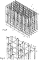
- a first type 8 of stand is in Fig. 5 shown.
- the first type 8 of uprights has a cross-like cross section, ie there are four ways of attaching a connecting element 11.
- a second type 9 of stand is in Fig. 6 shown.
- the second type 9 has a T-shaped cross section, ie there are three ways of attaching a connection element 11.
- the third type 10 of stands that are in Fig. 7 is shown, has an angled cross section, ie there are two ways of attaching a connecting element 11.
- stands of the first type 8 are arranged in the middle of the stacking storage arrangement.
- Posts of the second type 9 are arranged along the longitudinal and transverse sides of the stacking storage arrangement.
- Third type stands 10 are disposed at the corners of the stacker arrangement.
- the uprights 8 of the first type are arranged in several rows, the uprights in the rows are arranged with gaps.
- the uprights 8 of the first type are arranged in several rows, the uprights in the rows are arranged with gaps.
- connection element 11 is provided for fastening cross connectors 3 to stands 2.
- the stand 2 has a slot 12.
- the slot 12 can extend over the entire length of the corresponding stand 2. It extends inward into a cavity 13.
- the slot 12 is in a projection 14 ( Fig. 8 ) educated.
- the projection 14 has inclined outer sides. If a screw 15 is screwed into the slot 12, the outer sides are inclined with respect to an axis of the screw 15.
- the axis of the screw 15 is the axis of rotation around which the screw 15 is rotated when screwing in.
- connection element 11 has correspondingly inclined inner sides 16, ie the inclination of the inner sides 16 is adapted to the inclination of the corresponding outer sides of the projection 14. If the connecting element is brought into contact with the stand 2 when the screw 15 is tightened, the inner sides 16 of the connecting element 11 and the outer sides of the projection 14 work together as wedge surfaces, so that the width of the slot 12 is prevented from changing when the Screw 15 enlarged. This results in a defined width of the slot 12 to which the screw 15 can be adapted.
- the screw 15 is a self-tapping or self-tapping screw.
- the thread of the screw 15 is then not connected to the stand 2 and the projection 14 over its full circumference.
- the engagement between the projection 14 and the screw 15 is sufficient to be able to generate a clamping force with which the connecting element 11 is securely held on the stand 2.
- the slot 12 extends over the entire length of the stand 2. It is thus basically possible to mount a connection element 11 at any position on the stand 2.
- Cross connectors 3a which run in one direction, are mounted at a different height than cross connectors 3b, which run transversely to the first-mentioned cross connectors 3a.
- the associated connection elements 11 are accordingly also mounted at different heights.
- the cross connectors 3 are connected to the connecting elements 11 in a similar manner. This can be done using Fig. 9 detect.
- Each cross connector 3 in turn has a slot 17 into which a screw 18, which protrudes through the connecting element 11, is screwed.
- the slot 17 is in turn arranged in a projection 19 which has inclined outer sides. The outer sides are inclined towards the axis of rotation of the screw 18.
- the connection element 11 has a recess with inclined inner sides, the inclination of which is adapted to the inclination of the outer sides of the projection 19. This results in the same technical effect here as when the connection element 11 is fastened to the stand 2.
- the cross connector 3 likewise has a cavity 24.
- the slot 17 extends into the cavity. When the screw 18 is screwed into the slot 17, it can protrude into the cavity 24.
- connection element 11 is fastened to a stand in which it is brought into contact with a contact surface 21 of the stand 2 and in the process engages around the projection 14.
- the connection element 11 can then still be parallel to the longitudinal extension of the stand 2 moved until it reaches its desired position. After that, it is only necessary to fasten the connection element to the stand 2 with two screws 15.
- connection element 11 is fastened to an opposing stand 2.
- the connection element 11 has a support section 22 which is directed towards the respective other stand 2.
- the cross connector 3 is then placed on this support section 22 and connected to the connecting element 11 with one or two screws.
- Both the uprights 2 and the cross connectors 3 can be designed as extruded elements, for example made of aluminum.
- the stand 2 and the cross connector 3 can also be designed as roll profiles.
Landscapes
- Engineering & Computer Science (AREA)
- Mechanical Engineering (AREA)
- Assembled Shelves (AREA)
- Stackable Containers (AREA)
- Warehouses Or Storage Devices (AREA)
- Non-Reversible Transmitting Devices (AREA)
- Dram (AREA)
- Toys (AREA)
Abstract
Description
- Die vorliegende Erfindung betrifft eine Stapellageranordnung für Behälter mit mehreren Ständern, die durch Querverbinder miteinander verbunden sind.
- Eine derartige Stapellageranordnung ist beispielsweise aus
DE 42 03 823 C2 bekannt. - In einer Stapellageranordnung können Behälter in Form von Stapeln gelagert werden, d.h. mehrere Behälter sind in Schwerkraftrichtung übereinander angeordnet. Derartige Stapel können relativ eng benachbart angeordnet sein, so dass man einen zur Verfügung stehenden Bauraum mit einem hohen Nutzungsgrad nutzen kann. Die Ständer können hierbei an Ecken von Behälteraufnahmeräumen angeordnet sein. Die Querverbinder dienen dazu, der ganzen Anordnung eine gewisse mechanische Stabilität zu verleihen.
- Bei einer derartigen Stapellageranordnung gibt es mehrere Möglichkeiten. Man kann die Behälter von oben auf den jeweiligen Stapel aufsetzen und auch von dort entnehmen oder man kann die Behälter von unten an den Stapel ansetzen und auch von dort entnehmen. Im ersten Fall kann man die Ständer verwenden, um eine Fahrfläche abzustützen, auf der Bedienungsgeräte verfahren werden können, mit denen man die Behälter aus der Stapellageranordnung entnehmen kann. Im letzten Fall dienen die Ständer beispielsweise dazu, eine obere Abdeckung zu tragen, um die Stapellageranordnung abschließen zu können.
- Der Aufbau einer derartigen Stapellageranordnung erfordert einen erheblichen Aufwand.
- Der Erfindung liegt die Aufgabe zugrunde, den Aufwand beim Aufbau einer Stapellageranordnung klein zu halten.
- Diese Aufgabe wird bei einer Stapellageranordnung der eingangs genannten Art dadurch gelöst, dass mindestens ein Querverbinder über Anbindungselemente mit Ständern verbunden ist, von denen jedes an einer Anlagefläche eines Ständers anliegt, und die Anlagefläche einen Schlitz aufweist, in dem mindestens eine das Anbindungselement durchragende Schraube eingeschraubt ist.
- Mit einer derartigen Anordnung ist es nicht mehr erforderlich, die Ständer und die Querverbinder vor dem Verbinden so exakt zueinander auszurichten, dass Bohrungen in den Anbindungselementen und in den Ständern in einem ausreichenden Maße übereinstimmen. Vielmehr kann das Anbindungselement gegenüber dem jeweiligen Ständer in Richtung des Schlitzes bewegt werden. In den Schlitz kann eine Schraube eingeschraubt werden. Diese Schraube ist dann selbstschneidend oder selbstfurchend, d.h. sie erzeugt ihr Gewinde selbst. Da bereits ein Schlitz vorhanden ist, ist es nicht erforderlich, hierfür eine Bohrung herzustellen.
- Vorzugsweise geht der Schlitz über die Länge des Ständers durch. Damit ist es möglich, die Querverbinder praktisch an jeder beliebigen Position der Ständer zu befestigen. Man kann auch mehrere Querverbinder über die Länge des Ständers verteilen, ohne dass hier eine exakte Ausrichtung erforderlich wäre.
- Bevorzugterweise ist der Schlitz in einem Vorsprung ausgebildet und das Anbindungselement umgreift den Vorsprung seitlich. Im Vorsprung kann man eine ausreichende Materialstärke vorsehen. Damit wird die Schraube in ausreichendem Maße gehalten. Wenn das Anbindungselement den Vorsprung seitlich umgreift, kann man ein Spreizen des Ständers im Bereich des Vorsprungs vermeiden, so dass die Schraube auch sicher gehalten wird. Es ist dabei nicht erforderlich, dass das Anbindungselement seitlich über den Ständer hinausragt.
- Bevorzugterweise weist der Vorsprung Außenseiten auf, die gegenüber einer Achse der Schraube geneigt sind. Wenn es sich um eine symmetrische Neigung handelt, dann hat der Vorsprung im Querschnitt die Form eines Trapezes. Wenn das Anbindungselement mit der Schraube festgezogen wird, dann wirkt das Anbindungselement auf die Außenseiten des Vorsprungs und drängt die Außenseiten nach innen, so dass eine seitliche Kraft auf die Schraube ausgeübt wird, die die Haltefähigkeit und die Tragfähigkeit weiter erhöht.
- Vorzugsweise weist das Anbindungselement geneigte Innenseiten auf, deren Neigung an die zugehörigen Außenseiten angepasst ist. Damit ergibt sich eine Paarung von Keilflächen, die beim Anziehen der Schraube in Richtung einer Verringerung der Breite des Schlitzes wirken und damit der Schraube eine ausreichende Haltekraft vermitteln.
- Bevorzugterweise erstreckt sich der Schlitz bis in einen Hohlraum des Ständers. Der Ständer kann also hohl ausgebildet sein, was die Masse verringert und damit den Transport erleichtert. Darüber hinaus kann man durch Verwendung eines Ständers mit Hohlraum größere Toleranzen bei der Länge der Schraube zulassen, mit der das Anbindungselement mit dem Ständer verbunden wird. Darüber hinaus hat diese Ausgestaltung den Vorteil, dass die Herstellung des Ständers wirtschaftlich gestaltet werden kann. Wenn der Schlitz eine Verbindung vom Hohlraum nach außen herstellt, ist der Hohlraum nicht mehr geschlossen. Geschlossene Hohlräume sind bei einer Herstellung durch Extrusion weitaus aufwendiger herzustellen.
- Vorzugsweise ist der Ständer als Strangpresselement oder Rollformprofil ausgebildet. Ein Strangpresselement lässt sich kostengünstig fertigen. Es kann beispielsweise durch Extrusion hergestellt werden. Auch ein Rollformprofil lässt sich kostengünstig fertigen und ist als Halbzeug erhältlich.
- Vorzugsweise sind drei Arten von Ständern vorgesehen, wobei eine erste Art einen kreuzartigen Querschnitt, eine zweite Art einen T-förmigen Querschnitt und eine dritte Art einen abgewinkelten Querschnitt aufweist. Mit diesen drei Arten von Ständern kann man alle möglichen Konstellationen in einer Stapellageranordnung abdecken. Die erste Art von Ständern mit kreuzartigem Querschnitt kann inmitten der Stapellageranordnung angeordnet werden. Die zweite Art mit T-förmigem Querschnitt kann entlang den Rändern der Stapellageranordnung angeordnet werden. Die dritte Art mit abgewinkeltem Querschnitt kann an den Ecken der Stapellageranordnung angeordnet werden. Damit ist es möglich, die Stapellageranordnung an allen Seiten mit "glatten" Flächen auszubilden, also ohne, dass Elemente der Ständer nach außen vorstehen.
- Bevorzugterweise sind die Ständer der ersten Art in Reihen angeordnet, wobei die Ständer einer Reihe auf Lücke zu Ständern einer benachbarten Reihe angeordnet sind. Es ist also nicht erforderlich, an jeder Ecke eines jeden Behälterstapels, also an jeder Ecke eines Behälteraufnahmeraums, einen Ständer anzuordnen. Es reicht vielmehr aus, wenn die Ständer der ersten Art beispielsweise an Diagonalen der Behälteraufnahmeräume angeordnet sind. Damit spart man zum einen Material ein. Zum anderen bleibt ein Raum zwischen den Behälteraufnahmeräumen frei, den man beispielsweise verwenden kann, um eine Feuerlöscheinrichtung hier anzuordnen.
- Bevorzugterweise weisen die Querverbinder einen Schlitz auf, in den eine das Anbindungselement durchragende Schraube eingeschraubt ist. Man kann für die Befestigung der Querverbinder am Anbindungselement die gleiche Vorgehensweise verwenden wie beim Befestigen der Anbindungselemente an den Ständern.
- Vorzugsweise ist der Schlitz in einem Vorsprung angeordnet, den das Anbindungselement seitlich umgreift. Auch hier verhindert das Anbindungselement, dass sich der Schlitz beim Einschrauben der Schraube erweitert, also seine Breite vergrößert, so dass die Schraube mit der notwendigen Kraft im Schlitz festgehalten werden kann.
- Bevorzugterweise weist der Vorsprung Seitenflanken auf, die zu einer Achse der Schraube geneigt sind, und das Anbindungselement weist insbesondere geneigte Innenseiten auf, deren Neigung an die Neigung der Seitenflanken angepasst ist. Damit wirkt das Anbindungselement auf Keilflächen, so dass die Seiten des Vorsprungs in Richtung auf eine Verringerung der Breite des Schlitzes belastet werden.
- Vorzugsweise weist das Anbindungselement einen Tragabschnitt auf, an dem der Querverbinder befestigt ist, wobei der Tragabschnitt unterhalb des Querverbinders angeordnet ist. Dies erleichtert die Herstellung. Man verbindet zunächst das Anbindungselement mit dem Ständer an der gewünschten Höhe. Danach kann man den Querverbinder auf das Anbindungselement oder auf zwei Anbindungselemente auflegen und ggfs. die Anbindungselemente in gewünschter Weise ausrichten. Danach muss man lediglich noch eine oder mehrere Schrauben in jedes Anbindungselement einschrauben und der Querverbinder ist an dem Anbindungselement befestigt. Da auch der Querverbinder einen Schlitz aufweist, kann man hier gewisse Längentoleranzen akzeptieren.
- Vorzugsweise ist der Querverbinder als Strangpresselement oder Rollformprofil ausgebildet. Ein Strangpresselement oder Rollformprofil lässt sich kostengünstig herstellen. Man kann es in beliebiger Länge von einem Halbzeug ablängen. Dies kann bei den Querverbindern durchaus vor Ort passieren.
- Vorzugsweise erstreckt sich der Schlitz bis in einen Hohlraum im Querverbinder. Durch den Hohlraum kann der Querverbinder mit geringer Masse ausgebildet werden. Der Hohlraum erlaubt große Toleranzen bei der Länge der verwendeten Schraube.
- Die Erfindung wird im Folgenden anhand eines bevorzugten Ausführungsbeispiels in Verbindung mit einer Zeichnung beschrieben. Hierin zeigen:
- Fig. 1
- eine schematische Darstellung einer Stapellageranordnung,
- Fig. 2
- einen vergrößerten Ausschnitt aus
Fig. 1 , - Fig. 3
- eine vergrößerte Darstellung zur Erläuterung der Verbindung von Ständer und Querverbinder,
- Fig. 4
- einen Ausschnitt aus
Fig. 3 in Ansicht von unten, - Fig. 5
- eine erste Art von Ständern,
- Fig. 6
- eine zweite Art von Ständern,
- Fig. 7
- eine dritte Art von Ständern,
- Fig. 8
- einen Schnitt durch einen Ständer im Bereich von Anbindungselementen und
- Fig. 9
- einen Schnitt durch einen Querverbinder im Bereich eines Anbindungselements.
-
Fig. 1 zeigt schematisch eine Stapellageranordnung 1 mit Ständern 2, die durch Querverbinder 3 miteinander verbunden sind. - In der Stapellageranordnung sind mehrere Behälteraufnahmeräume 4 vorgesehen. Die Behälteraufnahmeräume 4 sind in Form einer Matrix angeordnet, d.h. es gibt Spalten und Reihen von Behälteraufnahmeräumen. Im vorliegenden Fall gibt es fünf Spalten und sechzehn Reihen.
- Unterhalb der Behälteraufnahmeräume 4 ist ein Beschickungsraum 5 angeordnet, in den man ein Beschickungsfahrzeug einfahren lassen kann, um einen Behälter in die Stapellageranordnung einzubringen oder einen Behälter aus der Stapellageranordnung zu entnehmen.
- Der Begriff "Behälter" ist hier nicht auf geschlossene Behälter beschränkt. Unter einem "Behälter" wird hier eine Einrichtung verstanden, die in der Lage ist, Produkte aufzunehmen und die stapelbar ist. Der "Behälter" kann also auch seitlich offen sein.
- Die Ständer 2 sind an einem Rahmen 6 befestigt, der über Stützelemente 7 auf dem Fußboden oder einer anderen Aufstandsfläche aufsteht.
- Wie man in
Fig. 2 und in denFig. 5 bis 7 erkennen kann, gibt es drei Arten von Ständern. Eine erste Art 8 von Ständern ist inFig. 5 dargestellt. Die erste Art 8 von Ständern hat einen kreuzartigen Querschnitt, d.h. es gibt vier Möglichkeiten, ein Anbindungselement 11 zu befestigen. - Eine zweite Art 9 von Ständern ist in
Fig. 6 dargestellt. Die zweite Art 9 hat einen T-förmigen Querschnitt, d.h. es gibt drei Möglichkeiten, ein Anbindungselement 11 zu befestigen. - Die dritte Art 10 von Ständern, die in
Fig.7 dargestellt ist, hat einen abgewinkelten Querschnitt, d.h. es gibt zwei Möglichkeiten, ein Anbindungselement 11 zu befestigen. - Wie man in
Fig. 2 erkennen kann, sind Ständer der ersten Art 8 inmitten der Stapellageranordnung angeordnet. Ständer der zweiten Art 9 sind entlang der Längs- und Querseiten der Stapellageranordnung angeordnet. Ständer der dritten Art 10 sind an den Ecken der Stapellageranordnung angeordnet. - Wie man insbesondere in
Fig. 2 erkennen kann, sind die Ständer 8 der ersten Art in mehreren Reihen angeordnet, wobei die Ständer in den Reihen auf Lücke angeordnet sind. Bei einem Behälteraufnahmeraum 4 im Inneren der Stapellageranordnung befindet sich also nicht an jeder Ecke des Behälteraufnahmeraums 4 ein Ständer, sondern die Ständer sind nur an diagonal gegenüberliegenden Ecken angeordnet. - Zur Befestigung von Querverbindern 3 an Ständern 2 ist das bereits erwähnte Anbindungselement 11 vorgesehen.
- Um das Anbindungselement 11 am Ständer 2 befestigen zu können, weist der Ständer 2 einen Schlitz 12 auf. Der Schlitz 12 kann sich über die gesamte Länge des entsprechenden Ständers 2 erstrecken. Er erstreckt sich nach innen bis in einen Hohlraum 13. Der Schlitz 12 ist dabei in einem Vorsprung 14 (
Fig. 8 ) ausgebildet. Der Vorsprung 14 hat geneigte Außenseiten. Wenn in den Schlitz 12 eine Schraube 15 eingeschraubt wird, dann sind die Außenseiten gegenüber einer Achse der Schraube 15 geneigt. Die Achse der Schraube 15 ist die Rotationsachse, um die die Schraube 15 beim Einschrauben gedreht wird. - Das Anbindungselement 11 weist entsprechend geneigte Innenseiten 16 auf, d.h. die Neigung der Innenseiten 16 ist an die Neigung der entsprechenden Außenseiten des Vorsprungs 14 angepasst. Wenn das Anbindungselement beim Festziehen der Schraube 15 zur Anlage an den Ständer 2 gebracht wird, dann wirken die Innenseiten 16 des Anbindungselements 11 und die Außenseiten des Vorsprungs 14 als Keilflächen zusammen, so dass verhindert wird, dass sich die Breite des Schlitzes 12 beim Einschrauben der Schraube 15 vergrößert. Damit ergibt sich eine definierte Breite des Schlitzes 12, an die die Schraube 15 angepasst werden kann.
- Die Schraube 15 ist eine selbstfurchende oder selbstschneidende Schraube. Das Gewinde der Schraube 15 steht dann zwar nicht über seinen vollen Umfang mit dem Ständer 2 und dem Vorsprung 14 in Verbindung. Der Eingriff zwischen dem Vorsprung 14 und der Schraube 15 reicht aber aus, um eine Spannkraft erzeugen zu können, mit der das Anbindungselement 11 sicher am Ständer 2 gehalten wird.
- Der Schlitz 12 geht über die gesamte Länge des Ständers 2 durch. Damit ist es im Grunde möglich, ein Anbindungselement 11 an jeder Position am Ständer 2 zu montieren.
- Der daraus resultierende Vorteil ist beispielsweise aus
Fig. 2 ersichtlich. Querverbinder 3a, die in eine Richtung verlaufen, sind in einer anderen Höhe montiert als Querverbinder 3b, die quer zu den erst genannten Querverbindern 3a verlaufen. Dementsprechend sind auch die dazu gehörigen Anbindungselemente 11 in unterschiedlichen Höhen montiert. - Die Querverbinder 3 sind auf ähnliche Weise mit den Anbindungselementen 11 verbunden. Dies lässt sich anhand von
Fig. 9 erkennen. Jeder Querverbinder 3 weist wiederum einen Schlitz 17 auf, in den eine Schraube 18, die das Anbindungselement 11 durchragt, eingeschraubt ist. Der Schlitz 17 ist wiederum in einem Vorsprung 19 angeordnet, der geneigte Außenseiten aufweist. Die Außenseiten sind zur Rotationsachse der Schraube 18 hin geneigt. Das Anbindungselement 11 weist eine Ausnehmung mit geneigten Innenseiten auf, deren Neigung an die Neigung der Außenseiten des Vorsprungs 19 angepasst sind. Damit ergibt sich hier die gleiche technische Wirkung wie bei der Befestigung des Anbindungselements 11 an dem Ständer 2. Der Querverbinder 3 weist ebenfalls einen Hohlraum 24 auf. Der Schlitz 17 erstreckt sich bis in den Hohlraum. Wenn die Schraube 18 in den Schlitz 17 eingeschraubt wird, kann sie bis in den Hohlraum 24 hineinragen. - Die Montage einer derartigen Stapellageranordnung gestaltet sich relativ einfach. Ein Anbindungselement 11 wird an einem Ständer befestigt, in dem es an eine Anlagefläche 21 des Ständers 2 zur Anlage gebracht wird und dabei den Vorsprung 14 umgreift. Das Anbindungselement 11 kann dann noch parallel zur Längserstreckung des Ständers 2 verschoben werden, bis es seine gewünschte Position erreicht hat. Danach ist es lediglich erforderlich, das Anbindungselement mit zwei Schrauben 15 am Ständer 2 zu befestigen.
- In gleicher Weise befestigt man ein weiteres Anbindungselement 11 an einem gegenüberliegenden Ständer 2. Das Anbindungselement 11 weist einen Tragabschnitt 22 auf, der zu dem jeweils anderen Ständer 2 hin gerichtet ist. Auf diesen Tragabschnitt 22 wird dann der Querverbinder 3 aufgelegt und mit ein oder zwei Schrauben mit dem Anbindungselement 11 verbunden.
- Sowohl die Ständer 2 als auch die Querverbinder 3 können als Strangpresselemente ausgebildet sein, beispielsweise aus Aluminium. Man kann die Ständer 2 und die Querverbinder 3 auch als Rollprofile ausbilden.
Claims (15)
- Stapellageranordnung (1) für Behälter mit mehreren Ständern (2), die durch Querverbinder (3) miteinander verbunden sind, dadurch gekennzeichnet, dass mindestens ein Querverbinder (3) über Anbindungselemente (11) mit Ständern (2) verbunden ist, von denen jedes an einer Anlagefläche (21) eines Ständers (2) anliegt, und die Anlagefläche (21) einen Schlitz (12) aufweist, in den mindestens eine das Anbindungselement (11) durchdringende Schraube (15) eingeschraubt ist.
- Stapellageranordnung nach Anspruch 1, dadurch gekennzeichnet, dass der Schlitz (12) über die Länge des Ständers (2) durchgeht.
- Stapellageranordnung nach Anspruch 1 oder 2, dadurch gekennzeichnet, dass der Schlitz (12) in einem Vorsprung (14) ausgebildet ist und das Anbindungselement (11) den Vorsprung (14) seitlich umgreift.
- Stapellageranordnung nach Anspruch 3, dadurch gekennzeichnet, dass der Vorsprung (14) Außenseiten aufweist, die gegenüber einer Achse der Schraube (15) geneigt sind.
- Stapellageranordnung nach Anspruch 4, dadurch gekennzeichnet, dass das Anbindungselement (11) geneigte Innenseiten (16) aufweist, deren Neigung an die zugehörigen Außenseiten angepasst ist.
- Stapellageranordnung nach einem der Ansprüche 1 bis 5, dadurch gekennzeichnet, dass sich der Schlitz (12) bis in einen Hohlraum (13) des Ständers (2) erstreckt.
- Stapellageranordnung nach einem der Ansprüche 1 bis 6, dadurch gekennzeichnet, dass der Ständer (2) als Strangpresselement oder Rollformprofil ausgebildet ist.
- Stapellageranordnung nach einem der Ansprüche 1 bis 7, dadurch gekennzeichnet, dass drei Arten (8, 9, 10) von Ständern (2) vorgesehen sind, wobei eine erste Art (8) einen kreuzartigen Querschnitt, eine zweite Art (9) einen T-förmigen Querschnitt und eine dritte Art (10) einen abgewinkelten Querschnitt aufweist.
- Stapellageranordnung nach Anspruch 8, dadurch gekennzeichnet, dass die Ständer (2) der ersten Art (8) in Reihen angeordnet sind, wobei die Ständer (2) einer Reihe auf Lücke zu Ständern (2) einer benachbarten Reihe angeordnet sind.
- Stapellageranordnung nach einem der Ansprüche 1 bis 9, dadurch gekennzeichnet, dass die Querverbinder (3) einen Schlitz (17) aufweisen, in den eine das Anbindungselement (11) durchragende Schraube (18) eingeschraubt ist.
- Stapellageranordnung nach Anspruch 10, dadurch gekennzeichnet, dass der Schlitz (17) in einem Vorsprung (19) angeordnet ist, den das Anbindungselement (11) seitlich umgreift.
- Stapellageranordnung nach Anspruch 11, dadurch gekennzeichnet, dass der Vorsprung (19) Seitenflanken aufweist, die zu einer Achse der Schraube (18) geneigt sind, und das Anbindungselement (11) insbesondere geneigte Innenseiten (20) aufweist, deren Neigung an die Neigung der Seitenflanken angepasst ist.
- Stapellageranordnung nach einem der Ansprüche 10 bis 12, dadurch gekennzeichnet, dass das Anbindungselement (11) einen Tragabschnitt (22) aufweist, an dem der Querverbinder (3) befestigt ist, wobei der Tragabschnitt (22) unterhalb des Querverbinders (3) angeordnet ist.
- Stapellageranordnung nach einem der Ansprüche 10 bis 13, dadurch gekennzeichnet, dass der Querverbinder (3) als Strangpresselement oder Rollformprofil ausgebildet sind.
- Stapellageranordnung nach einem der Ansprüche 10 bis 14, dadurch gekennzeichnet, dass sich der Schlitz (17) bis in einen Hohlraum (24) im Querverbinder erstreckt.
Priority Applications (5)
| Application Number | Priority Date | Filing Date | Title |
|---|---|---|---|
| EP19193379.5A EP3782928B1 (de) | 2019-08-23 | 2019-08-23 | Stapellageranordnung |
| PL19193379.5T PL3782928T3 (pl) | 2019-08-23 | 2019-08-23 | Układ do składowania w stosach |
| ES19193379T ES2940636T3 (es) | 2019-08-23 | 2019-08-23 | Disposición de almacenamiento por apilado |
| CN202010611716.0A CN112407709B (zh) | 2019-08-23 | 2020-06-30 | 堆垛存放组件 |
| US16/999,216 US11596227B2 (en) | 2019-08-23 | 2020-08-21 | Stacking storage arrangement |
Applications Claiming Priority (1)
| Application Number | Priority Date | Filing Date | Title |
|---|---|---|---|
| EP19193379.5A EP3782928B1 (de) | 2019-08-23 | 2019-08-23 | Stapellageranordnung |
Publications (2)
| Publication Number | Publication Date |
|---|---|
| EP3782928A1 true EP3782928A1 (de) | 2021-02-24 |
| EP3782928B1 EP3782928B1 (de) | 2022-11-23 |
Family
ID=67770360
Family Applications (1)
| Application Number | Title | Priority Date | Filing Date |
|---|---|---|---|
| EP19193379.5A Active EP3782928B1 (de) | 2019-08-23 | 2019-08-23 | Stapellageranordnung |
Country Status (5)
| Country | Link |
|---|---|
| US (1) | US11596227B2 (de) |
| EP (1) | EP3782928B1 (de) |
| CN (1) | CN112407709B (de) |
| ES (1) | ES2940636T3 (de) |
| PL (1) | PL3782928T3 (de) |
Cited By (2)
| Publication number | Priority date | Publication date | Assignee | Title |
|---|---|---|---|---|
| EP4238896A1 (de) * | 2022-03-03 | 2023-09-06 | Jungheinrich Aktiengesellschaft | Stapellageranordnung |
| EP4238903A1 (de) * | 2022-03-03 | 2023-09-06 | Jungheinrich Aktiengesellschaft | Blocklageranordnung |
Families Citing this family (3)
| Publication number | Priority date | Publication date | Assignee | Title |
|---|---|---|---|---|
| ES3031992T3 (en) * | 2019-08-23 | 2025-07-14 | Jungheinrich Ag | Stack storage assembly |
| EP3960657B1 (de) * | 2020-08-26 | 2024-03-27 | Jungheinrich Aktiengesellschaft | Stapellageranordnung |
| EP4238895B1 (de) * | 2022-03-03 | 2024-07-10 | Jungheinrich Aktiengesellschaft | Blocklageranordnung |
Citations (6)
| Publication number | Priority date | Publication date | Assignee | Title |
|---|---|---|---|---|
| DE2241061A1 (de) * | 1972-08-21 | 1974-02-28 | Bernd Ebeling | Bauelement fuer bauwerks-, behaelter-, moebel- o. dgl. konstruktionen |
| DE4203823C2 (de) | 1992-02-10 | 2001-03-08 | Robert Michaelides | Lagereinrichtung |
| DE20309331U1 (de) * | 2003-06-17 | 2003-09-11 | Richmann, Carsten Dieter, 44801 Bochum | Tragkonstruktion für ein Schrank- oder Regalbausystem |
| US20030206789A1 (en) * | 2002-04-05 | 2003-11-06 | Murata Kikai Kabushiki Kaisha | Automatic warehouse |
| EP2907410A1 (de) * | 2014-02-14 | 2015-08-19 | Syma Intercontinental AG | Bauelement, insbesondere Profil zur Verbindung von winklig zueinander angeordneten Teilelementen |
| CN110065750A (zh) * | 2018-06-08 | 2019-07-30 | 阿塔博迪克斯有限公司 | 在存储网格和外部工作站之间共用共同的机器人队列的改进的存储和取回系统 |
Family Cites Families (11)
| Publication number | Priority date | Publication date | Assignee | Title |
|---|---|---|---|---|
| BE786440A (fr) * | 1971-07-20 | 1973-01-19 | Interlake Inc | Verrou de charge |
| GB1364687A (en) * | 1971-08-05 | 1974-08-29 | Albrizzi Ltd | Modular joint components for constructional purposes |
| CA1146393A (en) * | 1980-12-03 | 1983-05-17 | Waldemar H. Greiner | Improvements in fence constructions and in fence elements therefor |
| US4652170A (en) * | 1984-09-24 | 1987-03-24 | Lew Hyok S | Slide connectors with frictional locking means |
| US6481177B1 (en) * | 2000-10-27 | 2002-11-19 | 80/20, Inc. | Inside corner connector for structural framing members |
| US6516955B1 (en) * | 2002-01-17 | 2003-02-11 | Eaton Corporation | Modular cabinet frame |
| CN2803149Y (zh) * | 2005-06-01 | 2006-08-09 | 湖州德马物流系统工程有限公司 | 无轨移动式立体货架 |
| US20080179581A1 (en) * | 2007-01-29 | 2008-07-31 | Northeastern Fence & Supply Corporation | Picket fence kit |
| CN201005355Y (zh) * | 2007-03-26 | 2008-01-16 | 卓加添 | 通廊式货架牛腿及其挂件组合装置 |
| US8689515B2 (en) * | 2010-04-26 | 2014-04-08 | Blanking Systems, Inc. | Hinge assembly for a frame structure |
| CN108482928A (zh) * | 2018-03-26 | 2018-09-04 | 李慧 | 太阳能组件立式缓存机 |
-
2019
- 2019-08-23 ES ES19193379T patent/ES2940636T3/es active Active
- 2019-08-23 EP EP19193379.5A patent/EP3782928B1/de active Active
- 2019-08-23 PL PL19193379.5T patent/PL3782928T3/pl unknown
-
2020
- 2020-06-30 CN CN202010611716.0A patent/CN112407709B/zh active Active
- 2020-08-21 US US16/999,216 patent/US11596227B2/en active Active
Patent Citations (6)
| Publication number | Priority date | Publication date | Assignee | Title |
|---|---|---|---|---|
| DE2241061A1 (de) * | 1972-08-21 | 1974-02-28 | Bernd Ebeling | Bauelement fuer bauwerks-, behaelter-, moebel- o. dgl. konstruktionen |
| DE4203823C2 (de) | 1992-02-10 | 2001-03-08 | Robert Michaelides | Lagereinrichtung |
| US20030206789A1 (en) * | 2002-04-05 | 2003-11-06 | Murata Kikai Kabushiki Kaisha | Automatic warehouse |
| DE20309331U1 (de) * | 2003-06-17 | 2003-09-11 | Richmann, Carsten Dieter, 44801 Bochum | Tragkonstruktion für ein Schrank- oder Regalbausystem |
| EP2907410A1 (de) * | 2014-02-14 | 2015-08-19 | Syma Intercontinental AG | Bauelement, insbesondere Profil zur Verbindung von winklig zueinander angeordneten Teilelementen |
| CN110065750A (zh) * | 2018-06-08 | 2019-07-30 | 阿塔博迪克斯有限公司 | 在存储网格和外部工作站之间共用共同的机器人队列的改进的存储和取回系统 |
Cited By (4)
| Publication number | Priority date | Publication date | Assignee | Title |
|---|---|---|---|---|
| EP4238896A1 (de) * | 2022-03-03 | 2023-09-06 | Jungheinrich Aktiengesellschaft | Stapellageranordnung |
| EP4238903A1 (de) * | 2022-03-03 | 2023-09-06 | Jungheinrich Aktiengesellschaft | Blocklageranordnung |
| US12565381B2 (en) | 2022-03-03 | 2026-03-03 | Jungheinrich Aktiengesellschaft | Block stacking arrangement |
| US12570468B2 (en) | 2022-03-03 | 2026-03-10 | Jungheinrich Aktiengesellschaft | Stacking storage arrangement |
Also Published As
| Publication number | Publication date |
|---|---|
| CN112407709B (zh) | 2022-10-04 |
| US20210052071A1 (en) | 2021-02-25 |
| US11596227B2 (en) | 2023-03-07 |
| EP3782928B1 (de) | 2022-11-23 |
| ES2940636T3 (es) | 2023-05-10 |
| CN112407709A (zh) | 2021-02-26 |
| PL3782928T3 (pl) | 2023-04-24 |
Similar Documents
| Publication | Publication Date | Title |
|---|---|---|
| EP3782928B1 (de) | Stapellageranordnung | |
| EP0310546B1 (de) | Variable Montagerahmen-Anordnung | |
| EP0994664A1 (de) | Satz von konstruktionselementen für möbel | |
| EP1259738A2 (de) | Profilverbindungseinrichtung | |
| EP3529430B1 (de) | Pfosten für eine pfosten-riegel-konstruktion | |
| EP4095331A1 (de) | Kopplungsvorrichtung für den modularen aufbau von bauwerken oder gegenständen | |
| DE2747064A1 (de) | Schalungselement | |
| EP4238896B1 (de) | Stapellageranordnung | |
| EP4163455B1 (de) | Fassaden- und/oder wandkonstruktion mit zugelementen | |
| DE29518886U1 (de) | Stahlbauskelettkonstruktion | |
| DE20010401U1 (de) | Halter zur Befestigung von Plattenmaterial, insbesondere von Glasscheiben an Standsäulen o.dgl. | |
| DE29924191U1 (de) | Regal | |
| CH719422B1 (de) | Verbindungseinrichtung für Tragelemente für ein Traggerüst sowie ein Traggerüst für Personen- und/oder Warenaufzüge | |
| EP3137699B1 (de) | Verfahren zur herstellung einer pfosten-riegel-verbindung | |
| AT526842B1 (de) | Rechtwinkelige Fachwerk-Struktur mit hoher Stabilität und Gestaltungsfreiheit, als Raumgliederung oder Regal | |
| EP1595038B1 (de) | Profilverbund | |
| DE4227531C2 (de) | Eckverbinder für ein Rahmengestell eines Schaltschrankes | |
| EP4526220B1 (de) | Werkstückträgerrahmen und werkstückträgerrahmensystem | |
| DE202004014452U1 (de) | Rollenhalterung | |
| EP3054810B1 (de) | Verbindungsknotenanordnung und bausatz | |
| EP4004305B1 (de) | Montagebaugruppe zur festlegung eines gerüsts an einem bauwerk | |
| EP4521993A1 (de) | Möbelsystem | |
| EP0443111A1 (de) | Verbindungselement zum Verbinden einer Säule mit einer rohrförmigen Strebe, zu verbindende Säule und Gestell mit wenigstens einer Säule und einer Strebe | |
| CH685146A5 (de) | Gestell für die Lagerung von länglichen Gegenständen sowie Profilelement für den Aufbau eines solchen Gestells. | |
| EP3514102B1 (de) | Regalbediengerät |
Legal Events
| Date | Code | Title | Description |
|---|---|---|---|
| PUAI | Public reference made under article 153(3) epc to a published international application that has entered the european phase |
Free format text: ORIGINAL CODE: 0009012 |
|
| STAA | Information on the status of an ep patent application or granted ep patent |
Free format text: STATUS: REQUEST FOR EXAMINATION WAS MADE |
|
| 17P | Request for examination filed |
Effective date: 20200514 |
|
| AK | Designated contracting states |
Kind code of ref document: A1 Designated state(s): AL AT BE BG CH CY CZ DE DK EE ES FI FR GB GR HR HU IE IS IT LI LT LU LV MC MK MT NL NO PL PT RO RS SE SI SK SM TR |
|
| AX | Request for extension of the european patent |
Extension state: BA ME |
|
| STAA | Information on the status of an ep patent application or granted ep patent |
Free format text: STATUS: EXAMINATION IS IN PROGRESS |
|
| 17Q | First examination report despatched |
Effective date: 20210316 |
|
| GRAP | Despatch of communication of intention to grant a patent |
Free format text: ORIGINAL CODE: EPIDOSNIGR1 |
|
| STAA | Information on the status of an ep patent application or granted ep patent |
Free format text: STATUS: GRANT OF PATENT IS INTENDED |
|
| INTG | Intention to grant announced |
Effective date: 20220714 |
|
| GRAS | Grant fee paid |
Free format text: ORIGINAL CODE: EPIDOSNIGR3 |
|
| GRAA | (expected) grant |
Free format text: ORIGINAL CODE: 0009210 |
|
| STAA | Information on the status of an ep patent application or granted ep patent |
Free format text: STATUS: THE PATENT HAS BEEN GRANTED |
|
| AK | Designated contracting states |
Kind code of ref document: B1 Designated state(s): AL AT BE BG CH CY CZ DE DK EE ES FI FR GB GR HR HU IE IS IT LI LT LU LV MC MK MT NL NO PL PT RO RS SE SI SK SM TR |
|
| REG | Reference to a national code |
Ref country code: GB Ref legal event code: FG4D Free format text: NOT ENGLISH |
|
| REG | Reference to a national code |
Ref country code: CH Ref legal event code: EP |
|
| REG | Reference to a national code |
Ref country code: AT Ref legal event code: REF Ref document number: 1533027 Country of ref document: AT Kind code of ref document: T Effective date: 20221215 Ref country code: DE Ref legal event code: R096 Ref document number: 502019006335 Country of ref document: DE |
|
| REG | Reference to a national code |
Ref country code: IE Ref legal event code: FG4D Free format text: LANGUAGE OF EP DOCUMENT: GERMAN |
|
| REG | Reference to a national code |
Ref country code: NL Ref legal event code: FP |
|
| REG | Reference to a national code |
Ref country code: LT Ref legal event code: MG9D |
|
| REG | Reference to a national code |
Ref country code: NO Ref legal event code: T2 Effective date: 20221123 |
|
| PG25 | Lapsed in a contracting state [announced via postgrant information from national office to epo] |
Ref country code: SE Free format text: LAPSE BECAUSE OF FAILURE TO SUBMIT A TRANSLATION OF THE DESCRIPTION OR TO PAY THE FEE WITHIN THE PRESCRIBED TIME-LIMIT Effective date: 20221123 Ref country code: PT Free format text: LAPSE BECAUSE OF FAILURE TO SUBMIT A TRANSLATION OF THE DESCRIPTION OR TO PAY THE FEE WITHIN THE PRESCRIBED TIME-LIMIT Effective date: 20230323 Ref country code: LT Free format text: LAPSE BECAUSE OF FAILURE TO SUBMIT A TRANSLATION OF THE DESCRIPTION OR TO PAY THE FEE WITHIN THE PRESCRIBED TIME-LIMIT Effective date: 20221123 Ref country code: FI Free format text: LAPSE BECAUSE OF FAILURE TO SUBMIT A TRANSLATION OF THE DESCRIPTION OR TO PAY THE FEE WITHIN THE PRESCRIBED TIME-LIMIT Effective date: 20221123 |
|
| REG | Reference to a national code |
Ref country code: ES Ref legal event code: FG2A Ref document number: 2940636 Country of ref document: ES Kind code of ref document: T3 Effective date: 20230510 |
|
| PG25 | Lapsed in a contracting state [announced via postgrant information from national office to epo] |
Ref country code: RS Free format text: LAPSE BECAUSE OF FAILURE TO SUBMIT A TRANSLATION OF THE DESCRIPTION OR TO PAY THE FEE WITHIN THE PRESCRIBED TIME-LIMIT Effective date: 20221123 Ref country code: LV Free format text: LAPSE BECAUSE OF FAILURE TO SUBMIT A TRANSLATION OF THE DESCRIPTION OR TO PAY THE FEE WITHIN THE PRESCRIBED TIME-LIMIT Effective date: 20221123 Ref country code: IS Free format text: LAPSE BECAUSE OF FAILURE TO SUBMIT A TRANSLATION OF THE DESCRIPTION OR TO PAY THE FEE WITHIN THE PRESCRIBED TIME-LIMIT Effective date: 20230323 Ref country code: HR Free format text: LAPSE BECAUSE OF FAILURE TO SUBMIT A TRANSLATION OF THE DESCRIPTION OR TO PAY THE FEE WITHIN THE PRESCRIBED TIME-LIMIT Effective date: 20221123 Ref country code: GR Free format text: LAPSE BECAUSE OF FAILURE TO SUBMIT A TRANSLATION OF THE DESCRIPTION OR TO PAY THE FEE WITHIN THE PRESCRIBED TIME-LIMIT Effective date: 20230224 |
|
| PG25 | Lapsed in a contracting state [announced via postgrant information from national office to epo] |
Ref country code: SM Free format text: LAPSE BECAUSE OF FAILURE TO SUBMIT A TRANSLATION OF THE DESCRIPTION OR TO PAY THE FEE WITHIN THE PRESCRIBED TIME-LIMIT Effective date: 20221123 Ref country code: RO Free format text: LAPSE BECAUSE OF FAILURE TO SUBMIT A TRANSLATION OF THE DESCRIPTION OR TO PAY THE FEE WITHIN THE PRESCRIBED TIME-LIMIT Effective date: 20221123 Ref country code: EE Free format text: LAPSE BECAUSE OF FAILURE TO SUBMIT A TRANSLATION OF THE DESCRIPTION OR TO PAY THE FEE WITHIN THE PRESCRIBED TIME-LIMIT Effective date: 20221123 Ref country code: DK Free format text: LAPSE BECAUSE OF FAILURE TO SUBMIT A TRANSLATION OF THE DESCRIPTION OR TO PAY THE FEE WITHIN THE PRESCRIBED TIME-LIMIT Effective date: 20221123 |
|
| P01 | Opt-out of the competence of the unified patent court (upc) registered |
Effective date: 20230628 |
|
| REG | Reference to a national code |
Ref country code: DE Ref legal event code: R097 Ref document number: 502019006335 Country of ref document: DE |
|
| PG25 | Lapsed in a contracting state [announced via postgrant information from national office to epo] |
Ref country code: SK Free format text: LAPSE BECAUSE OF FAILURE TO SUBMIT A TRANSLATION OF THE DESCRIPTION OR TO PAY THE FEE WITHIN THE PRESCRIBED TIME-LIMIT Effective date: 20221123 Ref country code: AL Free format text: LAPSE BECAUSE OF FAILURE TO SUBMIT A TRANSLATION OF THE DESCRIPTION OR TO PAY THE FEE WITHIN THE PRESCRIBED TIME-LIMIT Effective date: 20221123 |
|
| PLBE | No opposition filed within time limit |
Free format text: ORIGINAL CODE: 0009261 |
|
| STAA | Information on the status of an ep patent application or granted ep patent |
Free format text: STATUS: NO OPPOSITION FILED WITHIN TIME LIMIT |
|
| 26N | No opposition filed |
Effective date: 20230824 |
|
| PG25 | Lapsed in a contracting state [announced via postgrant information from national office to epo] |
Ref country code: SI Free format text: LAPSE BECAUSE OF FAILURE TO SUBMIT A TRANSLATION OF THE DESCRIPTION OR TO PAY THE FEE WITHIN THE PRESCRIBED TIME-LIMIT Effective date: 20221123 |
|
| PG25 | Lapsed in a contracting state [announced via postgrant information from national office to epo] |
Ref country code: MC Free format text: LAPSE BECAUSE OF FAILURE TO SUBMIT A TRANSLATION OF THE DESCRIPTION OR TO PAY THE FEE WITHIN THE PRESCRIBED TIME-LIMIT Effective date: 20221123 |
|
| PG25 | Lapsed in a contracting state [announced via postgrant information from national office to epo] |
Ref country code: MC Free format text: LAPSE BECAUSE OF FAILURE TO SUBMIT A TRANSLATION OF THE DESCRIPTION OR TO PAY THE FEE WITHIN THE PRESCRIBED TIME-LIMIT Effective date: 20221123 |
|
| PG25 | Lapsed in a contracting state [announced via postgrant information from national office to epo] |
Ref country code: LU Free format text: LAPSE BECAUSE OF NON-PAYMENT OF DUE FEES Effective date: 20230823 |
|
| PG25 | Lapsed in a contracting state [announced via postgrant information from national office to epo] |
Ref country code: LU Free format text: LAPSE BECAUSE OF NON-PAYMENT OF DUE FEES Effective date: 20230823 |
|
| REG | Reference to a national code |
Ref country code: BE Ref legal event code: MM Effective date: 20230831 |
|
| REG | Reference to a national code |
Ref country code: IE Ref legal event code: MM4A |
|
| PG25 | Lapsed in a contracting state [announced via postgrant information from national office to epo] |
Ref country code: IE Free format text: LAPSE BECAUSE OF NON-PAYMENT OF DUE FEES Effective date: 20230823 |
|
| PG25 | Lapsed in a contracting state [announced via postgrant information from national office to epo] |
Ref country code: IE Free format text: LAPSE BECAUSE OF NON-PAYMENT OF DUE FEES Effective date: 20230823 |
|
| PG25 | Lapsed in a contracting state [announced via postgrant information from national office to epo] |
Ref country code: BE Free format text: LAPSE BECAUSE OF NON-PAYMENT OF DUE FEES Effective date: 20230831 |
|
| PG25 | Lapsed in a contracting state [announced via postgrant information from national office to epo] |
Ref country code: BG Free format text: LAPSE BECAUSE OF FAILURE TO SUBMIT A TRANSLATION OF THE DESCRIPTION OR TO PAY THE FEE WITHIN THE PRESCRIBED TIME-LIMIT Effective date: 20221123 |
|
| PG25 | Lapsed in a contracting state [announced via postgrant information from national office to epo] |
Ref country code: BG Free format text: LAPSE BECAUSE OF FAILURE TO SUBMIT A TRANSLATION OF THE DESCRIPTION OR TO PAY THE FEE WITHIN THE PRESCRIBED TIME-LIMIT Effective date: 20221123 |
|
| PG25 | Lapsed in a contracting state [announced via postgrant information from national office to epo] |
Ref country code: CY Free format text: LAPSE BECAUSE OF FAILURE TO SUBMIT A TRANSLATION OF THE DESCRIPTION OR TO PAY THE FEE WITHIN THE PRESCRIBED TIME-LIMIT; INVALID AB INITIO Effective date: 20190823 |
|
| PG25 | Lapsed in a contracting state [announced via postgrant information from national office to epo] |
Ref country code: HU Free format text: LAPSE BECAUSE OF FAILURE TO SUBMIT A TRANSLATION OF THE DESCRIPTION OR TO PAY THE FEE WITHIN THE PRESCRIBED TIME-LIMIT; INVALID AB INITIO Effective date: 20190823 |
|
| PGFP | Annual fee paid to national office [announced via postgrant information from national office to epo] |
Ref country code: NL Payment date: 20250821 Year of fee payment: 7 |
|
| PGFP | Annual fee paid to national office [announced via postgrant information from national office to epo] |
Ref country code: ES Payment date: 20250917 Year of fee payment: 7 |
|
| PGFP | Annual fee paid to national office [announced via postgrant information from national office to epo] |
Ref country code: DE Payment date: 20250819 Year of fee payment: 7 |
|
| PGFP | Annual fee paid to national office [announced via postgrant information from national office to epo] |
Ref country code: NO Payment date: 20250820 Year of fee payment: 7 |
|
| PGFP | Annual fee paid to national office [announced via postgrant information from national office to epo] |
Ref country code: IT Payment date: 20250829 Year of fee payment: 7 Ref country code: PL Payment date: 20250813 Year of fee payment: 7 |
|
| PGFP | Annual fee paid to national office [announced via postgrant information from national office to epo] |
Ref country code: GB Payment date: 20250822 Year of fee payment: 7 |
|
| PGFP | Annual fee paid to national office [announced via postgrant information from national office to epo] |
Ref country code: FR Payment date: 20250821 Year of fee payment: 7 Ref country code: AT Payment date: 20250819 Year of fee payment: 7 |
|
| PGFP | Annual fee paid to national office [announced via postgrant information from national office to epo] |
Ref country code: CH Payment date: 20250901 Year of fee payment: 7 |
|
| PGFP | Annual fee paid to national office [announced via postgrant information from national office to epo] |
Ref country code: CZ Payment date: 20250808 Year of fee payment: 7 |
|
| PG25 | Lapsed in a contracting state [announced via postgrant information from national office to epo] |
Ref country code: TR Free format text: LAPSE BECAUSE OF FAILURE TO SUBMIT A TRANSLATION OF THE DESCRIPTION OR TO PAY THE FEE WITHIN THE PRESCRIBED TIME-LIMIT Effective date: 20221123 |