EP3783170B1 - Appareil de nettoyage par aspiration pour piscine - Google Patents
Appareil de nettoyage par aspiration pour piscine Download PDFInfo
- Publication number
- EP3783170B1 EP3783170B1 EP20164196.6A EP20164196A EP3783170B1 EP 3783170 B1 EP3783170 B1 EP 3783170B1 EP 20164196 A EP20164196 A EP 20164196A EP 3783170 B1 EP3783170 B1 EP 3783170B1
- Authority
- EP
- European Patent Office
- Prior art keywords
- driving wheel
- gear
- transmission mechanism
- engaged
- joint
- Prior art date
- Legal status (The legal status is an assumption and is not a legal conclusion. Google has not performed a legal analysis and makes no representation as to the accuracy of the status listed.)
- Active
Links
Images


Classifications
-
- E—FIXED CONSTRUCTIONS
- E04—BUILDING
- E04H—BUILDINGS OR LIKE STRUCTURES FOR PARTICULAR PURPOSES; SWIMMING OR SPLASH BATHS OR POOLS; MASTS; FENCING; TENTS OR CANOPIES, IN GENERAL
- E04H4/00—Swimming or splash baths or pools
- E04H4/14—Parts, details or accessories not otherwise provided for
- E04H4/16—Parts, details or accessories not otherwise provided for specially adapted for cleaning
-
- B—PERFORMING OPERATIONS; TRANSPORTING
- B62—LAND VEHICLES FOR TRAVELLING OTHERWISE THAN ON RAILS
- B62D—MOTOR VEHICLES; TRAILERS
- B62D55/00—Endless track vehicles
- B62D55/08—Endless track units; Parts thereof
- B62D55/14—Arrangement, location, or adaptation of rollers
- B62D55/15—Mounting devices, e.g. bushings, axles, bearings, sealings
-
- E—FIXED CONSTRUCTIONS
- E04—BUILDING
- E04H—BUILDINGS OR LIKE STRUCTURES FOR PARTICULAR PURPOSES; SWIMMING OR SPLASH BATHS OR POOLS; MASTS; FENCING; TENTS OR CANOPIES, IN GENERAL
- E04H4/00—Swimming or splash baths or pools
- E04H4/14—Parts, details or accessories not otherwise provided for
- E04H4/16—Parts, details or accessories not otherwise provided for specially adapted for cleaning
- E04H4/1618—Hand-held powered cleaners
- E04H4/1636—Suction cleaners
-
- B—PERFORMING OPERATIONS; TRANSPORTING
- B60—VEHICLES IN GENERAL
- B60K—ARRANGEMENT OR MOUNTING OF PROPULSION UNITS OR OF TRANSMISSIONS IN VEHICLES; ARRANGEMENT OR MOUNTING OF PLURAL DIVERSE PRIME-MOVERS IN VEHICLES; AUXILIARY DRIVES FOR VEHICLES; INSTRUMENTATION OR DASHBOARDS FOR VEHICLES; ARRANGEMENTS IN CONNECTION WITH COOLING, AIR INTAKE, GAS EXHAUST OR FUEL SUPPLY OF PROPULSION UNITS IN VEHICLES
- B60K17/00—Arrangement or mounting of transmissions in vehicles
- B60K17/04—Arrangement or mounting of transmissions in vehicles characterised by arrangement, location or kind of gearing
-
- B—PERFORMING OPERATIONS; TRANSPORTING
- B60—VEHICLES IN GENERAL
- B60K—ARRANGEMENT OR MOUNTING OF PROPULSION UNITS OR OF TRANSMISSIONS IN VEHICLES; ARRANGEMENT OR MOUNTING OF PLURAL DIVERSE PRIME-MOVERS IN VEHICLES; AUXILIARY DRIVES FOR VEHICLES; INSTRUMENTATION OR DASHBOARDS FOR VEHICLES; ARRANGEMENTS IN CONNECTION WITH COOLING, AIR INTAKE, GAS EXHAUST OR FUEL SUPPLY OF PROPULSION UNITS IN VEHICLES
- B60K8/00—Arrangement or mounting of propulsion units not provided for in one of main groups B60K1/00 - B60K7/00
-
- B—PERFORMING OPERATIONS; TRANSPORTING
- B62—LAND VEHICLES FOR TRAVELLING OTHERWISE THAN ON RAILS
- B62D—MOTOR VEHICLES; TRAILERS
- B62D55/00—Endless track vehicles
- B62D55/08—Endless track units; Parts thereof
- B62D55/18—Tracks
- B62D55/26—Ground engaging parts or elements
-
- E—FIXED CONSTRUCTIONS
- E04—BUILDING
- E04H—BUILDINGS OR LIKE STRUCTURES FOR PARTICULAR PURPOSES; SWIMMING OR SPLASH BATHS OR POOLS; MASTS; FENCING; TENTS OR CANOPIES, IN GENERAL
- E04H4/00—Swimming or splash baths or pools
- E04H4/14—Parts, details or accessories not otherwise provided for
- E04H4/16—Parts, details or accessories not otherwise provided for specially adapted for cleaning
- E04H4/1654—Self-propelled cleaners
- E04H4/1672—Connections to the pool water circulation system
-
- F—MECHANICAL ENGINEERING; LIGHTING; HEATING; WEAPONS; BLASTING
- F16—ENGINEERING ELEMENTS AND UNITS; GENERAL MEASURES FOR PRODUCING AND MAINTAINING EFFECTIVE FUNCTIONING OF MACHINES OR INSTALLATIONS; THERMAL INSULATION IN GENERAL
- F16H—GEARING
- F16H37/00—Combinations of mechanical gearings, not provided for in groups F16H1/00 - F16H35/00
- F16H37/02—Combinations of mechanical gearings, not provided for in groups F16H1/00 - F16H35/00 comprising essentially only toothed or friction gearings
- F16H37/04—Combinations of toothed gearings only
- F16H37/042—Combinations of toothed gearings only change gear transmissions in group arrangement
- F16H37/043—Combinations of toothed gearings only change gear transmissions in group arrangement without gears having orbital motion
- F16H2037/044—Combinations of toothed gearings only change gear transmissions in group arrangement without gears having orbital motion comprising a separate gearing unit for shifting between forward or reverse
-
- F—MECHANICAL ENGINEERING; LIGHTING; HEATING; WEAPONS; BLASTING
- F16—ENGINEERING ELEMENTS AND UNITS; GENERAL MEASURES FOR PRODUCING AND MAINTAINING EFFECTIVE FUNCTIONING OF MACHINES OR INSTALLATIONS; THERMAL INSULATION IN GENERAL
- F16H—GEARING
- F16H2702/00—Combinations of two or more transmissions
Definitions
- the present invention relates to the technical field of pool cleaning, and particularly relates to a suction cleaner for a pool.
- the suction cleaner for the pool is a cleaning device for the pool cleaning requirements.
- the suction cleaner for the pool can climb autonomously on the bottom and the wall of the pool, repeatedly clean the dirt in the pool, filter the water in the pool, and keep the water quality of the pool in a normal range, thereby becoming an indispensable device for the normal maintenance of the pool.
- a water outlet joint of the existing suction cleaner for the pool is rigidly connected with the cleaner.
- the cleaner When the cleaner travels to the pool wall for cleaning the wall cleaning and climbing, the cleaner will be affected by the water pipe. Because the water pipe also greatly bends, cleaner will be impacted to a certain degree. Meanwhile, the requirements for the flexibility of the water pipe are also high, which influences the wall climbing effect of the cleaner.
- the cleaner travels to the corner position of the pool, the cleaner is also easy to jam, thereby reducing the cleaning efficiency. Meanwhile, a slippage phenomenon is easy to occur when a reversing mechanism is reversed, and the phenomenon of tooth jamming causes unstable reversing, increases damage and abrasion of the teeth and reduces the service life
- Application CN109424223A discloses a hydraulic cleaner, which includes a housing,a hydraulic motor and a power output structure, according to the preamble of claim 1.
- the housing is provided with a water inlet at a bottom of the housing.
- the hydraulic motor is arranged in a middle of an interior of the housing; the hydraulic motor includes a cavity, a water inlet and a water outlet; a hollow part of the cavity is provided with a flow channel, a motor output shaft, a plurality of fan blade structures and a plurality of flow baffle pieces; ends of the flow channel are communicated with the water inlet and the water outlet, respectively.
- the power output structure includes a power transmission assembly, a caterpillar track and a wheel.
- a pool cleaner which includes a body having a debris inlet and a debris outlet.
- the body is adapted at the debris outlet for securement of either a water-suction hose connected to a remote suction system or a debris-collection device entrapping debris and passing water therethrough back into the pool.
- a venturi-line structure is secured with respect to the body.
- the venturi-line structure includes a venturi-line inlet adapted for connection of a waterflow line fed by a remote pump and a venturi jet located at the debris inlet to cause accelerated flow substantially thereacross and into the body when the cleaner is used as a pressure cleaner.
- the body includes a debris-inlet adjuster configured to reduce the debris inlet to adapt the cleaner for use as a suction cleaner,whereby the pool cleaner is interchangeably usable as a suction cleaner and as a pressure cleaner.
- a swimming pool vacuum cleaner brush head including a cover cooperating with: a first connector piece of a handle with a rotational joint about a first axis (X1X′1) to which an end of the handle can be connected, preferably in a fixed manner, a second connector piece for a suction tube, comprising a second tubular end-piece opening in a suction opening on the bottom face of the cover.
- the second connector piece includes a joint device which is free to rotate, permitting a rotation of the axis (Y2Y′2) of the second tubular end-piece about all axes of rotation called the second axis of rotation, perpendicular to and intersecting the centre (C) of the ball-joint, with the axis (YY′) of the suction opening, such as to permit a variable inclination ⁇ 2 of the axis (Y2Y′2) of the second tubular end-piece with relation to the axis (YY′) of the suction opening within a cone of apex half-angle (C) ⁇ 2 max with a value of at least 20°, preferably at least 30° with relation to the axis (YY′) of the suction opening.
- a joint device which is free to rotate, permitting a rotation of the axis (Y2Y′2) of the second tubular end-piece about all axes of rotation called the second axis of rotation, perpendicular to and intersecting the centre
- the purpose of the present invention is to provide a suction cleaner for a pool, so as to solve the technical problems that: a water pipe impacts a cleaner due to rigid connection between a water outlet joint of the cleaner and the cleaner, is easy to block when travelling to a corner position of a pool and affects cleaning efficiency; meanwhile, a slippage phenomenon is easy to occur when a reversing mechanism is reversed, and the phenomenon of tooth jamming causes unstable reversing, increases damage and abrasion of the teeth and reduces the service life.
- the suction cleaner according to the invention is realized according to claim 1.
- the rotating swing joint mechanism is composed of a swing head component, an upper cover plate and a lower fixing bracket, wherein the swing head component can swing back and forth and is installed between the upper cover plate and the lower fixing bracket; and the upper cover plate is fixedly connected with the lower fixing bracket.
- the swing head component is composed of a water outlet joint, a joint fixing bracket and a fixing collar, wherein a through hole is formed on the top of the joint fixing bracket; the water outlet joint penetrates through the through hole; the fixing collar is arranged at the through hole, is clamped with the joint fixing bracket, and is used for axially fixing the water outlet joint to the joint fixing bracket; and the water outlet joint can rotate relative to the joint fixing bracket.
- the first transmission mechanism includes a power transmission shaft and a transmission gear set, wherein the first gear and the transmission gear set are engaged with each other; one end of the power transmission shaft is engaged with the third transmission mechanism; the other end of the power transmission shaft is engaged with the fourth transmission mechanism; the power transmission shaft is fixedly connected with the transmission gear set; and the transmission gear set drives the power transmission shaft to rotate.
- one end of the power transmission shaft connected with the third transmission mechanism is a two-section gear structure.
- the second transmission mechanism is a reduction gear set;
- the third transmission mechanism includes a driving wheel, a third transmission driven wheel and an output shaft with a gear;
- a driving wheel gear is also arranged on one side of the driving wheel near the travelling mechanisms;
- the driving wheel gear and the driving wheel are of an integrated structure;
- the driving wheel gear is engaged with the third transmission driven wheel;
- the third transmission driven wheel is engaged with the output shaft;
- the output shaft is connected with the travelling mechanisms;
- the fourth transmission mechanism has the same structure as the third transmission mechanism.
- the driving wheel is a rotating body having both a driving wheel internal gear and a driving wheel external gear, and the driving wheel internal gear and the driving wheel external gear are in coaxial positions;
- the power transmission shaft in the first transmission mechanism is arranged between the driving wheel internal gear and the driving wheel external gear, and is engaged with the driving wheel internal gear or the driving wheel external gear; when the power transmission shaft is engaged with the driving wheel internal gear, engaging rotation directions are the same direction; and when the power transmission shaft is engaged with the driving wheel external gear, the engaging rotation directions are opposite directions.
- the reversing mechanism includes a guide member and a movable member; the guide member is a cam having a larger radius part and a smaller radius part; the guide member is connected with the second transmission mechanism; the second transmission mechanism drives the guide member to rotate; the movable member includes a roller and a roller bracket; the roller is arranged at one end of the roller bracket near the guide member and is rotatably connected with the roller bracket; the roller bracket can slide back and forth; the roller bracket is sleeved on the power transmission shaft in the first transmission mechanism; the roller bracket drives the power transmission shaft to slide back and forth together; and the guide member is in contact with the roller.
- the travelling mechanism is composed of a driven wheel, a driving wheel and a track; an inner surface and an outer surface of the track are provided with teeth; the teeth on the inner surface of the track are engaged with the driving wheel and the driven wheel; both sides of the track are convex and wrap the driving wheel and the driven wheel, or the driven wheel and the driving wheel are provided with grooves; the track is nested in the grooves of the driving wheel and the driven wheel; and the width of the track is smaller than the width of the grooves.
- the present invention has the following beneficial effects: by adopting the movable rotating swing joint mechanism, the present invention can swing and rotate back and forth relative to the travelling direction of the cleaner, which is beneficial for preventing the cleaner from being easily affected by a water pipe when the cleaner climbs up the wall of the pool for cleaning, so that the water pipe does not impact the cleaner and requirements for the flexibility of the water pipe are also reduced. Since there is no problem of corner jamming caused by the impact of the water pipe, the cleaning efficiency is also improved.
- one end of the power transmission shaft in the first transmission mechanism which is connected with the third transmission mechanism, is a two-section gear structure. When engaged with the driving wheel internal gear or the driving wheel external gear, the power transmission shaft can make smooth transition, and is not easy to cause tooth hitting and slippage phenomena.
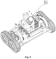
- the present invention provides a suction cleaner for a pool, including a housing 1 which is provided with a water inlet 10 in the middle position of the bottom; a hydraulic motor 2 used for providing power for the cleaner; travelling mechanisms 3 used for travelling; a reversing mechanism 4 used for changing a travelling direction; a rotating swing joint mechanism 5 used for connecting an external water outlet pipe and capable of swinging and rotating back and forth relative to the housing 1, wherein the hydraulic motor 2 and the reversing mechanism 4 are arranged in the housing 1; the hydraulic motor 2 is arranged in the middle position in the housing 1 and is communicated with the water inlet 10; the travelling mechanisms 3 are symmetrically arranged on the left side and the right side of the housing 1; the rotating swing joint mechanism 5 is arranged in the middle position on the top of the housing 1 and is communicated with the hydraulic motor 2; one end of a motor output shaft 21 of the hydraulic motor 2 is provided with a first gear 22 and the other end is provided with a second gear 23; the first gear
- the rotating swing joint mechanism 5 is composed of a swing head component 51, an upper cover plate 52 and a lower fixing bracket 53, wherein the swing head component 51 can swing back and forth and is installed between the upper cover plate 52 and the lower fixing bracket 53; and the upper cover plate 52 is fixedly connected with the lower fixing bracket 53.
- the swing head component 51 is matched with installing holes 521 on both sides of the upper cover plate 52 through a rotating shaft 54 or a pin, and the swing head component 51 swings back and forth by using the installing holes 521 on both sides of the upper cover plate 52 as circle centers.
- the swing head component 51 is composed of a water outlet joint 511, a joint fixing bracket 512 and a fixing collar 513, wherein a through hole 5121 is formed on the top of the joint fixing bracket 512; the water outlet joint 511 penetrates through the through hole 5121; the fixing collar 513 is arranged at the through hole 5121, is clamped with the joint fixing bracket 512, and is used for axially fixing the water outlet joint 511 to the joint fixing bracket 512; and since the water outlet joint 511 is not fixed circumferentially, the water outlet joint 511 is only axially fixed to the joint fixing bracket 512 and the water outlet joint 511 can rotate relative to the joint fixing bracket 512.
- the first transmission mechanism 6 includes a power transmission shaft 61 and a transmission gear set 62, wherein the first gear 22 and the transmission gear set 62 are engaged with each other; one end of the power transmission shaft 61 is engaged with the third transmission mechanism 8; the other end of the power transmission shaft 61 is engaged with the fourth transmission mechanism 9; the power transmission shaft 61 is fixedly connected with the transmission gear set 62; and the transmission gear set 62 drives the power transmission shaft 61 to rotate.
- the transmission gear set 62 includes a third gear 621, a fourth gear 622 and a fifth gear 623.
- the third gear 621 is fixedly arranged on the power transmission shaft 61.
- the fourth gear 622 and the fifth gear 623 are arranged between the first gear 22 and the third gear 621.
- the first gear 22 and the fourth gear 622 are engaged.
- the third gear 621 is engaged with the fifth gear 623, and the fourth gear 622 is engaged with the fifth gear 623, thereby transmitting power to the power transmission shaft 61.
- one end of the power transmission shaft 61 connected with the third transmission mechanism 8 is a structure of a two-section gear 611.
- a transmission ratio when the power transmission shaft 61 is engaged with the driving wheel internal gear 812 and a transmission ratio when the power transmission shaft 61 is engaged with the driving wheel external gear 813 can be set close to each other.
- the power transmission shaft 61 switches the engagement between the driving wheel external gear 813 and the driving wheel internal gear 812, a slippage phenomenon is not easy to occur.
- the second transmission mechanism 7 is a reduction gear set;
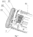
- the third transmission mechanism 8 includes a driving wheel 81, a third transmission driven wheel 82 and an output shaft 83 with a gear;
- a driving wheel gear 811 is also arranged on one side of the driving wheel 81 near the travelling mechanisms 3;
- the driving wheel gear 811 and the driving wheel 81 are of an integrated structure;
- the driving wheel gear 811 is engaged with the third transmission driven wheel 82;
- the third transmission driven wheel 82 is engaged with the output shaft 83;
- the output shaft 83 is connected with the travelling mechanisms 3 to drive the travelling mechanisms 3 to travel;
- the fourth transmission mechanism 9 and the third transmission mechanism 8 have the same structures and are symmetrically arranged.
- one end of the power transmission shaft 61 connected with the fourth transmission mechanism 9 is axially fixed, and can only be engaged with the driving wheel internal gear 812.
- the fourth transmission mechanism 9 can only rotate in one direction.
- the driving wheel 81 is a rotating body having both a driving wheel internal gear 812 and a driving wheel external gear 813, and the driving wheel internal gear 812 and the driving wheel external gear 813 are in coaxial positions;
- the power transmission shaft 61 in the first transmission mechanism 6 is arranged between the driving wheel internal gear 812 and the driving wheel external gear 813, and is engaged with the driving wheel internal gear 812 or the driving wheel external gear 813; when the power transmission shaft 61 is engaged with the driving wheel internal gear 812, engaging rotation directions are the same direction; and when the power transmission shaft 61 is engaged with the driving wheel external gear 813, the engaging rotation directions are opposite directions.
- the reversing mechanism 4 includes a guide member 41 and a movable member 42; the guide member 41 is a cam having a larger radius part and a smaller radius part; the guide member 41 is connected with the second transmission mechanism 7; the second transmission mechanism 7 drives the guide member 41 to rotate; the movable member 42 includes a roller 421 and a roller bracket 422; the roller 42 is arranged at one end of the roller bracket 422 near the guide member 41 and is rotatably connected with the roller bracket 422; the roller bracket 422 can slide back and forth; the roller bracket 422 is sleeved on the power transmission shaft 61 in the first transmission mechanism 6; the roller bracket 422 drives the power transmission shaft 61 to slide back and forth together; and the guide member 41 is in contact with the roller 421.
- a plurality of rolling skirt wings 11 are also symmetrically arranged at the bottom of the housing 1; the rolling skirt wings 11 are rotatably connected with the housing 1; and the rolling skirt wings 11 are used to increase suction around the water inlet at the bottom of the housing 1.
- the travelling mechanism 3 is composed of a driven wheel 31, a driving wheel 32 and a track 33; an inner surface and an outer surface of the track 33 are provided with teeth; the teeth on the inner surface of the track 33 are engaged with the driving wheel 31 and the driven wheel 32; the outer surface of the track 33 is also provided with a full circle of reinforcing belt; the reinforcing belt is perpendicular to the direction of the teeth on the outer surface of the track 33; both sides of the track 33 are convex and wrap the driving wheel 32 and the driven wheel 31, or the driven wheel 31 and the driving wheel 32 are provided with grooves; the track 33 is nested in the grooves of the driving wheel 32 and the driven wheel 31; and the width of the track 33 is smaller than the width of the grooves.
- the swing head component 51 of the rotating swing joint mechanism 5 can swing back and forth along the upper cover plate 52, and the water outlet joint 511 can rotate.
- the swing head component 51 of the rotating swing joint mechanism 5 can swing the direction to adapt to the connection with a water pipe, thereby reducing a torsional force on the cleaner due to the buoyancy of the water pipe, so that the cleaner is easy to climb up the wall of the pool, so as to increase the cleaning range of the pool.
- the working principle of the present invention is as follows: water is sucked in from the water inlet 10 at the bottom of the cleaner housing 1, is rotated by the impeller component 24, and is discharged from the water outlet joint 511.
- the water outlet joint 511 is connected with the water pipe; the water pipe is connected with a water pump; the impeller component 24 drives the motor output shaft 21; the first gear 22 at one end of the motor output shaft 21 drives the first transmission mechanism 6; and the second gear 23 at the other end drives the second transmission mechanism 7.
- the first transmission mechanism 6 transmits the power to the third transmission mechanism 8 and the fourth transmission mechanism 9 through the power transmission shaft 61; the third transmission mechanism 8 and the fourth transmission mechanism 9 drive the travelling mechanisms 3 on the left side and the right side of the housing 1; and the second transmission mechanism 7 drives the reversing mechanism 4.
- the second gear 23 drives the second transmission mechanism 7 to rotate.
- the second transmission mechanism 7 drives the guide member 41 engaged with the second transmission mechanism 7 to rotate together, and the guide member 41 is in contact with the roller 421.
- the roller 421 swings under the guidance of the guide member 41.
- the roller 421 drives the roller bracket 422 to slide back and forth.
- the roller bracket 422 drives the power transmission shaft 51 to slide back and forth together.
- one end of the power transmission shaft 61 engaged with the fourth transmission mechanism 9 is a fixed end, and one end of the power transmission shaft 61 engaged with the third transmission mechanism 8 is a movable end, only one end engaged with the third transmission mechanism 8 can slide back and forth to engage with the driving wheel internal gear 812 or the driving wheel external gear 813.
- engaging rotation directions are the same direction; and when the power transmission shaft 61 is engaged with the driving wheel external gear 813, the engaging rotation directions are opposite directions.
Landscapes
- Engineering & Computer Science (AREA)
- Architecture (AREA)
- Mechanical Engineering (AREA)
- Civil Engineering (AREA)
- Structural Engineering (AREA)
- Chemical & Material Sciences (AREA)
- Combustion & Propulsion (AREA)
- Transportation (AREA)
- General Engineering & Computer Science (AREA)
- Transmission Devices (AREA)
- Nozzles For Electric Vacuum Cleaners (AREA)
Claims (9)
- Aspirateur pour piscine, comprenant un boîtier (1) qui est pourvu d'une entrée d'eau (10) au milieu d'un fond du boîtier (1), et comprenant en outre :un moteur hydraulique (2) utilisé pour fournir de l'énergie audit aspirateur;mécanismes de déplacement (3) utilisés pour se déplacer;un mécanisme d'inversion (4) utilisé pour changer une direction de déplacement;un mécanisme de joint (5) utilisé pour connecter un tuyau de sortie d'eau externe;dans lequel ledit moteur hydraulique (2) et ledit mécanisme d'inversion (4) sont disposés dans ledit boîtier (1); ledit moteur hydraulique (2) est disposé au milieu dans ledit boîtier (1) et communique avec ladite entrée d'eau (10); lesdits mécanismes de déplacement (3) sont disposés symétriquement sur le côté gauche et le côté droit dudit boîtier (1); ledit mécanisme de joint (5) est disposé au milieu sur le dessus dudit boîtier (1) et est en communication avec ledit moteur hydraulique (2); une extrémité d'un arbre de sortie de moteur (21) dudit moteur hydraulique (2) est munie d'un premier engrenage (22) et l'autre extrémité est pourvue d'un deuxième engrenage (23); ledit premier engrenage (22) est en prise avec un premier mécanisme de transmission (6); ledit premier mécanisme de transmission (6) est respectivement en prise avec un troisième mécanisme de transmission (8) et un quatrième mécanisme de transmission (9); ledit troisième mécanisme de transmission (8) et ledit quatrième mécanisme de transmission (9) sont respectivement en prise avec lesdits mécanismes de déplacement (3) sur ledit côté gauche et ledit côté droit dudit boîtier (1); ledit deuxième engrenage (23) est en prise avec ledit mécanisme d'inversion (4) par l'intermédiaire dudit deuxième mécanisme de transmission (7); ledit mécanisme d'inversion (4) est connecté audit premier mécanisme de transmission (6); et ladite entrée d'eau (10), ledit moteur hydraulique (2) et ledit mécanisme de joint d'oscillation rotatif (5) forment un passage de circulation d'eau pour le passage d'un courant d'eau, caractérisé en ce que ledit mécanisme de joint (5) est un mécanisme de joint d'oscillation rotatif (5) capable de se balancer et de tourner d'avant en arrière par rapport audit boîtier, et en ce qu'une pluralité d'ailettes de jupe roulante (11) sont disposées symétriquement audit fond dudit boîtier (1); lesdites ailes de jupe roulante (11) étant reliées de manière rotative audit boîtier (1); et lesdites ailes de jupe roulante (11) étant utilisées pour augmenter l'aspiration autour de ladite entrée d'eau (10) audit fond dudit boîtier (1).
- Aspirateur pour piscine selon la revendication 1, dans lequel ledit mécanisme de joint rotatif (5) est composé d'un élément de tête pivotante (51), d'une plaque de couverture supérieure (52) et d'un support de fixation inférieur (53), dans lequel ledit élément de tête pivotante (51) peut osciller d'avant en arrière et est installé entre ladite plaque de couverture supérieure (52) et ledit support de fixation inférieur (53); et ladite plaque de couverture supérieure (52) est reliée de manière fixe audit support de fixation inférieur (53).
- Aspirateur pour piscine selon la revendication 2, dans lequel ledit élément de tête pivotante (51) est composé d'un joint de sortie d'eau (511), d'un support de fixation de joint (512) et d'un collier de fixation (513), dans lequel un trou traversant (5121) est formé sur le dessus dudit support de fixation de joint (512); ledit joint de sortie d'eau (511) pénètre à travers ledit trou traversant (5121); ledit collier de fixation (513) est disposé au niveau dudit trou traversant (5121), est serré avec ledit support de fixation de joint (512) et est utilisé pour fixer axialement ledit joint de sortie d'eau (511) audit support de fixation de joint (512); et ledit joint de sortie d'eau (511) peut tourner par rapport audit support de fixation de joint (512).
- Aspirateur pour piscine selon la revendication 1, dans lequel ledit premier mécanisme de transmission (6) comprend un arbre de transmission de puissance (61) et un train d'engrenages de transmission (62), dans lequel ledit premier engrenage (22) et ledit train d'engrenages de transmission (62) sont engagés l'un avec l'autre; une extrémité dudit arbre de transmission de puissance (61) est en prise avec ledit troisième mécanisme de transmission (8); l'autre extrémité dudit arbre de transmission de puissance (61) est en prise avec ledit quatrième mécanisme de transmission (9); ledit arbre de transmission de puissance (61) est connecté de manière fixe audit train d'engrenages de transmission (62); et ledit train d'engrenages de transmission (62) entraîne ledit arbre de transmission de puissance (61) à tourner.
- Aspirateur pour piscine selon la revendication 4, dans lequel une extrémité dudit arbre de transmission de puissance (61) reliée audit troisième mécanisme de transmission (8) est une structure d'engrenage à deux sections.
- Aspirateur pour piscine selon la revendication 1, caractérisé en ce que ledit deuxième mécanisme de transmission (7) est un train d'engrenages de réducteur; ledit troisième mécanisme de transmission (8) comprend une roue motrice (81), une troisième roue menée de transmission (82) et un arbre de sortie (83) avec un engrenage; un engrenage de roue motrice (811) est également agencé sur un côté de ladite roue motrice (81) à proximité desdits mécanismes de déplacement (3); ledit engrenage de roue motrice (811) et ladite roue motrice (81) sont d'une structure intégrée; ledit engrenage de roue motrice (811) est en prise avec ladite troisième roue menée de transmission (82); ladite troisième roue menée de transmission (82) est en prise avec ledit arbre de sortie (83); ledit arbre de sortie (83) est connecté auxdits mécanismes de déplacement (3); et ledit quatrième mécanisme de transmission (9) a ladite même structure que ledit troisième mécanisme de transmission (8).
- Aspirateur pour piscine selon la revendication 6, caractérisé en ce que ladite roue motrice (81) est un corps tournant ayant à la fois un engrenage interne de roue motrice (812) et un engrenage externe de roue motrice (813), et ledit engrenage interne de roue motrice (812) et ledit engrenage externe de roue motrice (813) sont dans des positions coaxiales; ledit arbre de transmission de puissance (61) dans ledit premier mécanisme de transmission (6) est disposé entre ledit engrenage interne de roue motrice (812) et ledit engrenage externe de roue motrice (813), et est en prise avec ledit engrenage interne de roue motrice (812) ou ledit engrenage extérieur de la roue motrice (813); lorsque ledit arbre de transmission de puissance (61) est en prise avec ledit engrenage interne de roue d'entraînement (812), sens de rotation d'engagement sont les mêmes; et lorsque ledit arbre de transmission de puissance (61) est en prise avec ledit engrenage externe de roue motrice (813), lesdits sens de rotation d'engagement sont opposés.
- Aspirateur pour piscine selon la revendication 1, caractérisé en ce que ledit mécanisme d'inversion (4) comprend un élément de guidage (41) et un élément mobile (42); ledit élément de guidage (41) est une came ayant une partie de rayon plus grand et une partie de rayon plus petit; ledit élément de guidage (41) est connecté audit second mécanisme de transmission (7); ledit deuxième mécanisme de transmission (7) entraîne en rotation ledit élément de guidage (41); ledit élément mobile (42) comprend un rouleau (421) et un support de rouleau (422); ledit rouleau (42) est agencé à une extrémité dudit support de rouleau (422) à proximité dudit élément de guidage (41) et est connecté de manière rotative audit support de rouleau (422); ledit support de rouleau (422) peut coulisser d'avant en arrière; ledit support de rouleau (422) est gainé sur ledit arbre de transmission de puissance (61) dans ledit premier mécanisme de transmission (6); ledit support de rouleau (422) entraîne ledit arbre de transmission de puissance (61) pour coulisser ensemble d'avant en arrière; et ledit élément de guidage (41) est en contact avec ledit rouleau (421).
- Aspirateur pour piscine selon la revendication 1, caractérisé en ce que ledit mécanisme de déplacement (3) est composé d'une roue menée (31), d'une roue motrice (32) et d'une chenille (33); une surface intérieure et une surface extérieure de ladite chenille (33) sont munies de dents; lesdites dents sur ladite surface intérieure de ladite chenille (33) sont en prise avec ladite roue motrice (31) et ladite roue menée (32); deux côtés de ladite chenille (33) sont convexes et enveloppent ladite roue motrice (32) et ladite roue menée (31), ou ladite roue menée (31) et ladite roue motrice (32) sont pourvues de rainures; ladite chenille (33) est emboîtée dans lesdites rainures de ladite roue motrice (32) et de ladite roue menée (31); et la largeur de ladite chenille (33) est inférieure à la largeur desdites rainures.
Applications Claiming Priority (1)
| Application Number | Priority Date | Filing Date | Title |
|---|---|---|---|
| CN201910774384.5A CN112412128B (zh) | 2019-08-21 | 2019-08-21 | 一种水池水能清洁器 |
Publications (2)
| Publication Number | Publication Date |
|---|---|
| EP3783170A1 EP3783170A1 (fr) | 2021-02-24 |
| EP3783170B1 true EP3783170B1 (fr) | 2021-10-13 |
Family
ID=69903028
Family Applications (1)
| Application Number | Title | Priority Date | Filing Date |
|---|---|---|---|
| EP20164196.6A Active EP3783170B1 (fr) | 2019-08-21 | 2020-03-19 | Appareil de nettoyage par aspiration pour piscine |
Country Status (4)
| Country | Link |
|---|---|
| US (1) | US20210053631A1 (fr) |
| EP (1) | EP3783170B1 (fr) |
| CN (1) | CN112412128B (fr) |
| ES (1) | ES2899193T3 (fr) |
Families Citing this family (7)
| Publication number | Priority date | Publication date | Assignee | Title |
|---|---|---|---|---|
| US11124983B2 (en) | 2020-02-19 | 2021-09-21 | Pavel Sebor | Automatic pool cleaner |
| CN113738163B (zh) * | 2021-08-17 | 2022-10-18 | 浙江金泽泳池设备工程有限公司 | 一种自适应泳池底壁形状的清洁装置 |
| AU2022439389A1 (en) * | 2022-02-09 | 2024-09-26 | Suzhou Smorobot Technology Co., Ltd. | Pool cleaning robot with externally engaged roller brush |
| CN114876250B (zh) * | 2022-05-31 | 2023-09-19 | 广州城市理工学院 | 一种水下清洁设备的移动方法 |
| CN115156214B (zh) * | 2022-06-29 | 2024-04-19 | 中建八局第一建设有限公司 | 一种不锈钢集水槽清理装置 |
| CN218092271U (zh) | 2022-09-02 | 2022-12-20 | 深圳市思傲拓科技有限公司 | 一种泳池清洁机器人的动力输出结构 |
| CN221219891U (zh) * | 2023-10-16 | 2024-06-25 | 上海荣威塑胶工业有限公司 | 水池清洁装置 |
Family Cites Families (19)
| Publication number | Priority date | Publication date | Assignee | Title |
|---|---|---|---|---|
| US5799351A (en) * | 1990-09-21 | 1998-09-01 | Rief; Dieter J. | Swimming pool cleaner with vibratory power |
| US5293659A (en) * | 1990-09-21 | 1994-03-15 | Rief Dieter J | Automatic swimming pool cleaner |
| US5775741A (en) * | 1996-01-26 | 1998-07-07 | Baracuda International Corporation | Swimming pool cleaner swivel assembly |
| US6155657A (en) * | 1998-08-21 | 2000-12-05 | Aqua Products Inc. | Drive track for self-propelled pool cleaner |
| US6782578B1 (en) * | 2000-05-26 | 2004-08-31 | Poolvergnuegen | Swimming pool pressure cleaner with internal steering mechanism |
| US6733046B1 (en) * | 2002-10-24 | 2004-05-11 | Pollvergnuegen | Hose swivel connection apparatus |
| CN2820820Y (zh) * | 2005-08-18 | 2006-09-27 | 关汝壁 | 升降台的传动机构 |
| FR2930798A1 (fr) * | 2008-05-02 | 2009-11-06 | Gatech Sarl | Tete de balai d'aspirateur de piscine |
| US8225446B2 (en) * | 2008-11-17 | 2012-07-24 | Heavy Gain Limited | Pool cleaning vehicle with endless loop track |
| US8402585B2 (en) * | 2009-10-19 | 2013-03-26 | Poolvergnuegen | Convertible pressure/suction swimming pool cleaner |
| CN101708117A (zh) * | 2009-11-26 | 2010-05-19 | 苏州莱尔特清洁器具有限公司 | 一种地板刷 |
| WO2012009082A2 (fr) * | 2010-06-28 | 2012-01-19 | Zodiac Pool Care Europe | Appareils de nettoyage de piscine automatiques et leurs composants |
| WO2014070301A1 (fr) * | 2012-10-30 | 2014-05-08 | Pavel Sebor | Appareil et méthode de nettoyage de piscine à entraînement par turbine |
| EP3187665B1 (fr) * | 2013-08-30 | 2021-04-14 | Hayward Industries, Inc. | Système de nettoyage de piscine |
| CN104083874B (zh) * | 2014-07-24 | 2016-02-03 | 明玉平 | 自动换挡赛车 |
| EP3394366B1 (fr) * | 2015-12-02 | 2020-10-14 | NC Brands L.P. | Système de direction pour nettoyeurs de piscine |
| CN206693693U (zh) * | 2017-03-18 | 2017-12-01 | 宁波博尔富泳池设备有限公司 | 一种泳池清洁设备 |
| CN109424223A (zh) * | 2017-08-28 | 2019-03-05 | 宁波市普世达泳池用品有限公司 | 一种水能清洁器 |
| CN109723251B (zh) * | 2019-01-29 | 2023-10-20 | 温州米修实业有限公司 | 泳池自动清洁车 |
-
2019
- 2019-08-21 CN CN201910774384.5A patent/CN112412128B/zh active Active
-
2020
- 2020-03-19 ES ES20164196T patent/ES2899193T3/es active Active
- 2020-03-19 EP EP20164196.6A patent/EP3783170B1/fr active Active
- 2020-03-19 US US16/824,594 patent/US20210053631A1/en not_active Abandoned
Also Published As
| Publication number | Publication date |
|---|---|
| US20210053631A1 (en) | 2021-02-25 |
| ES2899193T3 (es) | 2022-03-10 |
| EP3783170A1 (fr) | 2021-02-24 |
| CN112412128B (zh) | 2022-02-15 |
| CN112412128A (zh) | 2021-02-26 |
Similar Documents
| Publication | Publication Date | Title |
|---|---|---|
| EP3783170B1 (fr) | Appareil de nettoyage par aspiration pour piscine | |
| US6782578B1 (en) | Swimming pool pressure cleaner with internal steering mechanism | |
| US5933899A (en) | Low pressure automatic swimming pool cleaner | |
| US6854148B1 (en) | Four-wheel-drive automatic swimming pool cleaner | |
| US12385273B2 (en) | Turbine-driven swimming pool cleaning apparatus | |
| CN102037198B (zh) | 带有高压清洁射流的泳池清洁器 | |
| EP0565226B1 (fr) | Appareil de nettoyage pour piscine | |
| US9512630B2 (en) | Automated swimming pool cleaner having and angled jet drive propulsion system | |
| EP2769033B1 (fr) | Nettoyeur de bassin muni d'ensemble temporisateur hydraulique | |
| EP2769034B1 (fr) | Nettoyeur de bassin muni d'ensemble à vide à venturi à étages multiples | |
| US20070157413A1 (en) | Pool cleaning robot | |
| CN102037199A (zh) | 带有高压清洁射流的泳池清洁器 | |
| CA2414101C (fr) | Dispositif de nettoyage a air comprime pour piscine pourvu d'un mecanisme de guidage interne | |
| US9845609B2 (en) | Swimming pool pressure cleaner including automatic timing mechanism | |
| US20080244842A1 (en) | Motorised Pool-Cleaning Device Comprising Freewheel Rotary Movement Means | |
| CA2414117C (fr) | Dispositif automatique de nettoyage de piscine a quatre roues motrices | |
| CN224134314U (zh) | 一种可切换喷口方向的泵推装置及泳池清洁机器人 | |
| ZA200302322B (en) | Four-wheel-drive automatic swimming pool cleaner. |
Legal Events
| Date | Code | Title | Description |
|---|---|---|---|
| PUAI | Public reference made under article 153(3) epc to a published international application that has entered the european phase |
Free format text: ORIGINAL CODE: 0009012 |
|
| STAA | Information on the status of an ep patent application or granted ep patent |
Free format text: STATUS: REQUEST FOR EXAMINATION WAS MADE |
|
| 17P | Request for examination filed |
Effective date: 20200319 |
|
| AK | Designated contracting states |
Kind code of ref document: A1 Designated state(s): AL AT BE BG CH CY CZ DE DK EE ES FI FR GB GR HR HU IE IS IT LI LT LU LV MC MK MT NL NO PL PT RO RS SE SI SK SM TR |
|
| AX | Request for extension of the european patent |
Extension state: BA ME |
|
| GRAP | Despatch of communication of intention to grant a patent |
Free format text: ORIGINAL CODE: EPIDOSNIGR1 |
|
| STAA | Information on the status of an ep patent application or granted ep patent |
Free format text: STATUS: GRANT OF PATENT IS INTENDED |
|
| INTG | Intention to grant announced |
Effective date: 20210720 |
|
| GRAS | Grant fee paid |
Free format text: ORIGINAL CODE: EPIDOSNIGR3 |
|
| GRAA | (expected) grant |
Free format text: ORIGINAL CODE: 0009210 |
|
| STAA | Information on the status of an ep patent application or granted ep patent |
Free format text: STATUS: THE PATENT HAS BEEN GRANTED |
|
| AK | Designated contracting states |
Kind code of ref document: B1 Designated state(s): AL AT BE BG CH CY CZ DE DK EE ES FI FR GB GR HR HU IE IS IT LI LT LU LV MC MK MT NL NO PL PT RO RS SE SI SK SM TR |
|
| REG | Reference to a national code |
Ref country code: GB Ref legal event code: FG4D |
|
| REG | Reference to a national code |
Ref country code: CH Ref legal event code: EP |
|
| REG | Reference to a national code |
Ref country code: DE Ref legal event code: R096 Ref document number: 602020000714 Country of ref document: DE |
|
| REG | Reference to a national code |
Ref country code: IE Ref legal event code: FG4D |
|
| REG | Reference to a national code |
Ref country code: AT Ref legal event code: REF Ref document number: 1438313 Country of ref document: AT Kind code of ref document: T Effective date: 20211115 |
|
| REG | Reference to a national code |
Ref country code: LT Ref legal event code: MG9D |
|
| REG | Reference to a national code |
Ref country code: NL Ref legal event code: MP Effective date: 20211013 |
|
| REG | Reference to a national code |
Ref country code: ES Ref legal event code: FG2A Ref document number: 2899193 Country of ref document: ES Kind code of ref document: T3 Effective date: 20220310 |
|
| REG | Reference to a national code |
Ref country code: AT Ref legal event code: MK05 Ref document number: 1438313 Country of ref document: AT Kind code of ref document: T Effective date: 20211013 |
|
| PG25 | Lapsed in a contracting state [announced via postgrant information from national office to epo] |
Ref country code: RS Free format text: LAPSE BECAUSE OF FAILURE TO SUBMIT A TRANSLATION OF THE DESCRIPTION OR TO PAY THE FEE WITHIN THE PRESCRIBED TIME-LIMIT Effective date: 20211013 Ref country code: LT Free format text: LAPSE BECAUSE OF FAILURE TO SUBMIT A TRANSLATION OF THE DESCRIPTION OR TO PAY THE FEE WITHIN THE PRESCRIBED TIME-LIMIT Effective date: 20211013 Ref country code: FI Free format text: LAPSE BECAUSE OF FAILURE TO SUBMIT A TRANSLATION OF THE DESCRIPTION OR TO PAY THE FEE WITHIN THE PRESCRIBED TIME-LIMIT Effective date: 20211013 Ref country code: BG Free format text: LAPSE BECAUSE OF FAILURE TO SUBMIT A TRANSLATION OF THE DESCRIPTION OR TO PAY THE FEE WITHIN THE PRESCRIBED TIME-LIMIT Effective date: 20220113 Ref country code: AT Free format text: LAPSE BECAUSE OF FAILURE TO SUBMIT A TRANSLATION OF THE DESCRIPTION OR TO PAY THE FEE WITHIN THE PRESCRIBED TIME-LIMIT Effective date: 20211013 |
|
| PG25 | Lapsed in a contracting state [announced via postgrant information from national office to epo] |
Ref country code: IS Free format text: LAPSE BECAUSE OF FAILURE TO SUBMIT A TRANSLATION OF THE DESCRIPTION OR TO PAY THE FEE WITHIN THE PRESCRIBED TIME-LIMIT Effective date: 20220213 Ref country code: SE Free format text: LAPSE BECAUSE OF FAILURE TO SUBMIT A TRANSLATION OF THE DESCRIPTION OR TO PAY THE FEE WITHIN THE PRESCRIBED TIME-LIMIT Effective date: 20211013 Ref country code: PT Free format text: LAPSE BECAUSE OF FAILURE TO SUBMIT A TRANSLATION OF THE DESCRIPTION OR TO PAY THE FEE WITHIN THE PRESCRIBED TIME-LIMIT Effective date: 20220214 Ref country code: PL Free format text: LAPSE BECAUSE OF FAILURE TO SUBMIT A TRANSLATION OF THE DESCRIPTION OR TO PAY THE FEE WITHIN THE PRESCRIBED TIME-LIMIT Effective date: 20211013 Ref country code: NO Free format text: LAPSE BECAUSE OF FAILURE TO SUBMIT A TRANSLATION OF THE DESCRIPTION OR TO PAY THE FEE WITHIN THE PRESCRIBED TIME-LIMIT Effective date: 20220113 Ref country code: NL Free format text: LAPSE BECAUSE OF FAILURE TO SUBMIT A TRANSLATION OF THE DESCRIPTION OR TO PAY THE FEE WITHIN THE PRESCRIBED TIME-LIMIT Effective date: 20211013 Ref country code: LV Free format text: LAPSE BECAUSE OF FAILURE TO SUBMIT A TRANSLATION OF THE DESCRIPTION OR TO PAY THE FEE WITHIN THE PRESCRIBED TIME-LIMIT Effective date: 20211013 Ref country code: HR Free format text: LAPSE BECAUSE OF FAILURE TO SUBMIT A TRANSLATION OF THE DESCRIPTION OR TO PAY THE FEE WITHIN THE PRESCRIBED TIME-LIMIT Effective date: 20211013 Ref country code: GR Free format text: LAPSE BECAUSE OF FAILURE TO SUBMIT A TRANSLATION OF THE DESCRIPTION OR TO PAY THE FEE WITHIN THE PRESCRIBED TIME-LIMIT Effective date: 20220114 |
|
| REG | Reference to a national code |
Ref country code: DE Ref legal event code: R097 Ref document number: 602020000714 Country of ref document: DE |
|
| PG25 | Lapsed in a contracting state [announced via postgrant information from national office to epo] |
Ref country code: SM Free format text: LAPSE BECAUSE OF FAILURE TO SUBMIT A TRANSLATION OF THE DESCRIPTION OR TO PAY THE FEE WITHIN THE PRESCRIBED TIME-LIMIT Effective date: 20211013 Ref country code: SK Free format text: LAPSE BECAUSE OF FAILURE TO SUBMIT A TRANSLATION OF THE DESCRIPTION OR TO PAY THE FEE WITHIN THE PRESCRIBED TIME-LIMIT Effective date: 20211013 Ref country code: RO Free format text: LAPSE BECAUSE OF FAILURE TO SUBMIT A TRANSLATION OF THE DESCRIPTION OR TO PAY THE FEE WITHIN THE PRESCRIBED TIME-LIMIT Effective date: 20211013 Ref country code: EE Free format text: LAPSE BECAUSE OF FAILURE TO SUBMIT A TRANSLATION OF THE DESCRIPTION OR TO PAY THE FEE WITHIN THE PRESCRIBED TIME-LIMIT Effective date: 20211013 Ref country code: DK Free format text: LAPSE BECAUSE OF FAILURE TO SUBMIT A TRANSLATION OF THE DESCRIPTION OR TO PAY THE FEE WITHIN THE PRESCRIBED TIME-LIMIT Effective date: 20211013 Ref country code: CZ Free format text: LAPSE BECAUSE OF FAILURE TO SUBMIT A TRANSLATION OF THE DESCRIPTION OR TO PAY THE FEE WITHIN THE PRESCRIBED TIME-LIMIT Effective date: 20211013 |
|
| PLBE | No opposition filed within time limit |
Free format text: ORIGINAL CODE: 0009261 |
|
| STAA | Information on the status of an ep patent application or granted ep patent |
Free format text: STATUS: NO OPPOSITION FILED WITHIN TIME LIMIT |
|
| 26N | No opposition filed |
Effective date: 20220714 |
|
| REG | Reference to a national code |
Ref country code: DE Ref legal event code: R119 Ref document number: 602020000714 Country of ref document: DE |
|
| PG25 | Lapsed in a contracting state [announced via postgrant information from national office to epo] |
Ref country code: MC Free format text: LAPSE BECAUSE OF FAILURE TO SUBMIT A TRANSLATION OF THE DESCRIPTION OR TO PAY THE FEE WITHIN THE PRESCRIBED TIME-LIMIT Effective date: 20211013 Ref country code: AL Free format text: LAPSE BECAUSE OF FAILURE TO SUBMIT A TRANSLATION OF THE DESCRIPTION OR TO PAY THE FEE WITHIN THE PRESCRIBED TIME-LIMIT Effective date: 20211013 |
|
| REG | Reference to a national code |
Ref country code: BE Ref legal event code: MM Effective date: 20220331 |
|
| PG25 | Lapsed in a contracting state [announced via postgrant information from national office to epo] |
Ref country code: LU Free format text: LAPSE BECAUSE OF NON-PAYMENT OF DUE FEES Effective date: 20220319 Ref country code: IE Free format text: LAPSE BECAUSE OF NON-PAYMENT OF DUE FEES Effective date: 20220319 Ref country code: DE Free format text: LAPSE BECAUSE OF NON-PAYMENT OF DUE FEES Effective date: 20221001 |
|
| PG25 | Lapsed in a contracting state [announced via postgrant information from national office to epo] |
Ref country code: BE Free format text: LAPSE BECAUSE OF NON-PAYMENT OF DUE FEES Effective date: 20220331 |
|
| PG25 | Lapsed in a contracting state [announced via postgrant information from national office to epo] |
Ref country code: IT Free format text: LAPSE BECAUSE OF FAILURE TO SUBMIT A TRANSLATION OF THE DESCRIPTION OR TO PAY THE FEE WITHIN THE PRESCRIBED TIME-LIMIT Effective date: 20211013 |
|
| REG | Reference to a national code |
Ref country code: CH Ref legal event code: PL |
|
| PG25 | Lapsed in a contracting state [announced via postgrant information from national office to epo] |
Ref country code: LI Free format text: LAPSE BECAUSE OF NON-PAYMENT OF DUE FEES Effective date: 20230331 Ref country code: CH Free format text: LAPSE BECAUSE OF NON-PAYMENT OF DUE FEES Effective date: 20230331 |
|
| PG25 | Lapsed in a contracting state [announced via postgrant information from national office to epo] |
Ref country code: MK Free format text: LAPSE BECAUSE OF FAILURE TO SUBMIT A TRANSLATION OF THE DESCRIPTION OR TO PAY THE FEE WITHIN THE PRESCRIBED TIME-LIMIT Effective date: 20211013 Ref country code: CY Free format text: LAPSE BECAUSE OF FAILURE TO SUBMIT A TRANSLATION OF THE DESCRIPTION OR TO PAY THE FEE WITHIN THE PRESCRIBED TIME-LIMIT Effective date: 20211013 |
|
| PG25 | Lapsed in a contracting state [announced via postgrant information from national office to epo] |
Ref country code: HU Free format text: LAPSE BECAUSE OF FAILURE TO SUBMIT A TRANSLATION OF THE DESCRIPTION OR TO PAY THE FEE WITHIN THE PRESCRIBED TIME-LIMIT; INVALID AB INITIO Effective date: 20200319 |
|
| PG25 | Lapsed in a contracting state [announced via postgrant information from national office to epo] |
Ref country code: MT Free format text: LAPSE BECAUSE OF FAILURE TO SUBMIT A TRANSLATION OF THE DESCRIPTION OR TO PAY THE FEE WITHIN THE PRESCRIBED TIME-LIMIT Effective date: 20211013 |
|
| GBPC | Gb: european patent ceased through non-payment of renewal fee |
Effective date: 20240319 |
|
| PG25 | Lapsed in a contracting state [announced via postgrant information from national office to epo] |
Ref country code: GB Free format text: LAPSE BECAUSE OF NON-PAYMENT OF DUE FEES Effective date: 20240319 |
|
| PG25 | Lapsed in a contracting state [announced via postgrant information from national office to epo] |
Ref country code: GB Free format text: LAPSE BECAUSE OF NON-PAYMENT OF DUE FEES Effective date: 20240319 |
|
| PGFP | Annual fee paid to national office [announced via postgrant information from national office to epo] |
Ref country code: ES Payment date: 20250411 Year of fee payment: 6 |
|
| PGFP | Annual fee paid to national office [announced via postgrant information from national office to epo] |
Ref country code: FR Payment date: 20250520 Year of fee payment: 6 |
|
| PG25 | Lapsed in a contracting state [announced via postgrant information from national office to epo] |
Ref country code: TR Free format text: LAPSE BECAUSE OF FAILURE TO SUBMIT A TRANSLATION OF THE DESCRIPTION OR TO PAY THE FEE WITHIN THE PRESCRIBED TIME-LIMIT Effective date: 20211013 |
|
| PG25 | Lapsed in a contracting state [announced via postgrant information from national office to epo] |
Ref country code: SI Free format text: LAPSE BECAUSE OF FAILURE TO SUBMIT A TRANSLATION OF THE DESCRIPTION OR TO PAY THE FEE WITHIN THE PRESCRIBED TIME-LIMIT Effective date: 20211013 |