EP3783175A1 - Cam lock assembly kit - Google Patents
Cam lock assembly kit Download PDFInfo
- Publication number
- EP3783175A1 EP3783175A1 EP19192199.8A EP19192199A EP3783175A1 EP 3783175 A1 EP3783175 A1 EP 3783175A1 EP 19192199 A EP19192199 A EP 19192199A EP 3783175 A1 EP3783175 A1 EP 3783175A1
- Authority
- EP
- European Patent Office
- Prior art keywords
- cam
- adapter
- axle
- profile
- cam lock
- Prior art date
- Legal status (The legal status is an assumption and is not a legal conclusion. Google has not performed a legal analysis and makes no representation as to the accuracy of the status listed.)
- Granted
Links
Images
Classifications
-
- E—FIXED CONSTRUCTIONS
- E05—LOCKS; KEYS; WINDOW OR DOOR FITTINGS; SAFES
- E05C—BOLTS OR FASTENING DEVICES FOR WINGS, SPECIALLY FOR DOORS OR WINDOWS
- E05C3/00—Fastening devices with bolts moving pivotally or rotatively
- E05C3/02—Fastening devices with bolts moving pivotally or rotatively without latching action
- E05C3/04—Fastening devices with bolts moving pivotally or rotatively without latching action with operating handle or equivalent member rigid with the bolt
- E05C3/041—Fastening devices with bolts moving pivotally or rotatively without latching action with operating handle or equivalent member rigid with the bolt rotating about an axis perpendicular to the surface on which the fastener is mounted
- E05C3/042—Fastening devices with bolts moving pivotally or rotatively without latching action with operating handle or equivalent member rigid with the bolt rotating about an axis perpendicular to the surface on which the fastener is mounted the handle being at one side, the bolt at the other side or inside the wing
-
- E—FIXED CONSTRUCTIONS
- E05—LOCKS; KEYS; WINDOW OR DOOR FITTINGS; SAFES
- E05B—LOCKS; ACCESSORIES THEREFOR; HANDCUFFS
- E05B63/00—Locks or fastenings with special structural characteristics
- E05B63/0056—Locks with adjustable or exchangeable lock parts
-
- E—FIXED CONSTRUCTIONS
- E05—LOCKS; KEYS; WINDOW OR DOOR FITTINGS; SAFES
- E05C—BOLTS OR FASTENING DEVICES FOR WINGS, SPECIALLY FOR DOORS OR WINDOWS
- E05C21/00—Arrangements or combinations of wing fastening, securing, or holding devices, not covered by a single preceding main group; Locking kits
Definitions
- Various example embodiments relate to a cam lock assembly kit.
- a cam lock has two main parts: a cam lock base and a rotatable cam as a latch.
- the cam lock may be used in various types of cabinets or other types of furniture, for example.
- Different markets use different kinds of cams, straight or offset cams, with different kinds of through cam holes, for example. Consequently, different markets require different versions of the cam lock, which complicates design and manufacturing and increases costs.
- FIG. 1A and FIG. 1B illustrating a cam lock assembly kit 100.
- the kit 100 comprises six main parts: a first cam 130, a second cam 160, a bolt 180, a cam lock base 110, a first adapter 140, and a second adapter 170.
- the first cam 130 is provided with a first through cam hole 132.
- the second cam 160 is provided with a second through cam hole 162.
- the cams 130, 160 may be offset cams as shown, with offset parts 134, 164, but they may also be straight cams. Likewise, the external forms of the cams 130, 160 may be different from those illustrated.
- the cams 130, 160 may be commercially available standard cams, i.e., they are not specifically manufactured for the cam lock assembly kit 100.
- the second through cam hole 162 is of a different shape than the first through cam hole 132. This requirement may be set by different markets. For example, in some markets the cam hole 132, 162 may be of a rectangular shape with each side being 9 millimetres, whereas in some other markets, each side is 7 millimetres. Also, other shapes of the cam hole 132, 162, are also possible, like an oblong shape of the first through cam hole 132 of the first cam 130, with dimensions 8.1 millimetres x 11.7 millimetres, for example.
- the bolt 180 is provided with a male thread 182.
- a head of the bolt 180 may be provided with a suitable fitting, such as a hexagonal head, a screw head, an Allen head, or a Torx head, for example, in order to enable an easy assembly of the cam lock with matching tools.
- the cam lock base 110 comprises an axle 118 to receive mechanical rotation from a first end 120 of the axle 118 and transmit the rotation to a second end 122 of the axle 118.
- the cam lock base 110 also includes mechanics and possibly electronics needed to allow or block rotation of the cam 130, 160.
- a body 112 of the cam lock base 110 houses the various components.
- the cam lock base 110 may comprise a knob 116, which may also house various electronics such as an NFC (Near Field Communication) antenna.
- the turn-knob 116 may also receive the mechanical rotation from the user and pass it on to the axle 118.
- the applicant, iLOQ Oy has invented many improvements for electromechanical locks, such as those disclosed in various EP and US patent applications / patents, incorporated herein as references in all jurisdictions where applicable. A complete discussion of all those details is not repeated here, but the reader is advised to consult those applications.
- the cam lock base 110 may utilize energy generation from a key insertion for powering the mechanics/electronics, or it may harvest the energy utilizing NFC technology, both being technologies developed by the applicant, but the cam lock base 110 may also be implemented with a purely mechanical technology, or with an alternative electromechanical technology.
- the second end 122 of the axle 118 comprises a hollow 124 with a female thread 126 to couple with the male thread 182 of the bolt 180.
- Each of the first adapter 140 and the second adapter 170 comprise a main profile 150A, 150B dimensioned to clearance fit into the hollow 124 of the cam lock base 110, and a through adapter hole 152A, 152B dimensioned to receive the male thread 182 of the bolt 180 to couple with the female thread 126 of the hollow 124 of the axle 118.
- first adapter 140 comprises a first auxiliary profile 142 dimensioned to clearance fit the first through cam hole 132 of the first cam 130.
- second adapter 170 comprises a second auxiliary profile 172 dimensioned to clearance fit the second through cam hole 162 of the second cam 160.
- first auxiliary profile 142 and the second auxiliary profile 172 may be designed, dimensioned and manufactured to clearance fit the through cam holes 132, 162, i.e., it is not the other way around.
- the bolt 180 couples either the first cam 130 between the first adapter 140 and the second end 122 of the axle 118, or the second cam 160 between the second adapter 170 and the second end 122 of the axle 118.
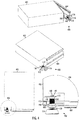
- FIG. 4 illustrates a cam lock 400 assembled from the cam lock assembly kit 100 and fitted to a door 404 of a cabinet 402.
- a detailed view 406 shows the way the cam 130 is located between the adapter 140 and the second end 122 of the axle 118.
- the cam lock 400 is locked, as the cam 130 is behind a striker 412 of the cam lock 400. Note that the shape of the cam 130 in FIG. 4 is different from those shown in FIG. 1A and FIG. 1B
- FIG. 4 also illustrates that the cam lock base 114, provided with male threads 114 and a flange 408, may be attached with a matching bolt 410 to the cabinet door 404.
- the hollow 124 comprises an oblong shape transversal to an axial direction 128 of the axle 118.
- Such oblong shape enables rotation of the axle 118 such that the adapter 140/170 stays securely in place in spite of the torque provided by the rotation.
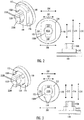
- FIG. 2 and FIG. 3 illustrate that the matching main profile 150A, 150B of the adapter 140, 170 also comprises the oblong shape: one side 212 of the main profile 150A, 150B in one transversal direction 210 is longer than another side 202 of the main profile 150A, 150B in another transversal direction 200.
- the female thread 126 extends away from a bottom of the hollow 124.
- the depth of female thread 126 is dimensioned so that a reliable coupling is achieved.
- the main profile 150A of the first adapter 140 is superimposed on the first auxiliary profile 142 such that a diameter 202 of the main profile 150A is smaller than a diameter 204 of the first auxiliary profile 142 in at least one transversal direction 200
- the main profile 150B of the second adapter 170 is superimposed on the second auxiliary profile 172 such that the diameter 202 of the main profile 150B is smaller than a diameter 206 of the second auxiliary profile 172 in at least one transversal direction 200.
- a diameter 212 of the main profile 150A is also smaller than a diameter 214 of the first auxiliary profile 142 in another transversal direction 210, whereas in FIG.
- a diameter 212 of the main profile 150B is equal to a diameter 216 of the second auxiliary profile 172 in the other transversal direction 210.
- the through adapter hole 152A, 152B is positioned in the middle of the main profile 150A, 150B. This feature increases the robustness of the adapter 140/170.
- a curved sidewall 220A, 220B of the through adapter hole 152A, 152B extends beyond an oblong shape 202, 212 of the main profile 150A, 150B forming an integral bulge 222A, 222B to the oblong shape 202, 212.
- first auxiliary profile 142 is of an angular shape
- second auxiliary profile 172 is of an angular shape.
- edges of the angular shape of the first auxiliary profile 142 are rounded 230
- edges of the angular shape of the second auxiliary profile 172 are bevelled 232.
- the main profile 150A, 150B of the first adapter 140 or the second adapter 170 when assembled, is countersunk into the hollow 124 of the axle 118, and the first auxiliary profile 142 or the second auxiliary profile 172 is outside of the hollow 124 of the axle 118.
- FIG. 1A shows planes 144, 174 of the adapter 140, 170 forming flanges, which rest against the other end 122 of the axle 118 when the cam lock 400 is assembled. These flanges 144, 174 limit depth of the countersinking.
- planes 224, 226 of the adapter 140, 170 may rest against the bottom of the hollow 124.
- the first adapter 140 and the second adapter 170 each comprise a flange 146, 176 next to the first auxiliary profile 142 and the second auxiliary profile 172.
- the bolt 180 presses either the first cam 130 between the flange 146 of the first adapter 140 and the second end 122 of the axle 118, or the second cam 160 between the flange 176 of the second adapter 170 and the second end 122 of the axle 118.
Landscapes
- Engineering & Computer Science (AREA)
- Mechanical Engineering (AREA)
- Structural Engineering (AREA)
- Connection Of Plates (AREA)
- Mutual Connection Of Rods And Tubes (AREA)
Abstract
Description
- Various example embodiments relate to a cam lock assembly kit.
- A cam lock has two main parts: a cam lock base and a rotatable cam as a latch. The cam lock may be used in various types of cabinets or other types of furniture, for example. Different markets use different kinds of cams, straight or offset cams, with different kinds of through cam holes, for example. Consequently, different markets require different versions of the cam lock, which complicates design and manufacturing and increases costs.
-
US 2009/0071209 A1 ,US 9,605,455 B2 US 2012/0248794 A1 disclose various types of adapters for cam locks, but none of them solves the mentioned problem. - According to an aspect, there is provided subject matter of independent claims. Dependent claims define some example embodiments.
- One or more examples of implementations are set forth in more detail in the accompanying drawings and the description of embodiments.
- Some example embodiments will now be described with reference to the accompanying drawings, in which
-
FIG. 1A and FIG. 1B illustrate example embodiments of a cam lock assembly kit from two different views; -
FIG. 2 illustrates example embodiments of a first adapter from three different views; -
FIG. 3 illustrates example embodiments of a second adapter from three different views; and -
FIG. 4 illustrates example embodiments of an assembled cam lock fitted to a cabinet from three different views and one magnified detail view. - The following embodiments are only examples. Although the specification may refer to "an" embodiment in several locations, this does not necessarily mean that each such reference is to the same embodiment(s), or that the feature only applies to a single embodiment. Single features of different embodiments may also be combined to provide other embodiments. Furthermore, words "comprising" and "including" should be understood as not limiting the described embodiments to consist of only those features that have been mentioned and such embodiments may contain also features/structures that have not been specifically mentioned.
- Reference numbers, both in the description of the example embodiments and in the claims, serve to illustrate the example embodiments with reference to the drawings, without limiting it to these examples only.
- The embodiments and features, if any, disclosed in the following description that do not fall under the scope of the independent claims are to be interpreted as examples useful for understanding various embodiments of the invention.
- Let us first study
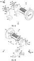
FIG. 1A and FIG. 1B illustrating a camlock assembly kit 100. - The
kit 100 comprises six main parts: afirst cam 130, asecond cam 160, abolt 180, acam lock base 110, afirst adapter 140, and asecond adapter 170. - The
first cam 130 is provided with a first throughcam hole 132. - The
second cam 160 is provided with a second throughcam hole 162. - The
cams offset parts cams cams lock assembly kit 100. - The second through
cam hole 162 is of a different shape than the first throughcam hole 132. This requirement may be set by different markets. For example, in some markets thecam hole cam hole cam hole 132 of thefirst cam 130, with dimensions 8.1 millimetres x 11.7 millimetres, for example. - The
bolt 180 is provided with amale thread 182. A head of thebolt 180 may be provided with a suitable fitting, such as a hexagonal head, a screw head, an Allen head, or a Torx head, for example, in order to enable an easy assembly of the cam lock with matching tools. - The
cam lock base 110 comprises anaxle 118 to receive mechanical rotation from afirst end 120 of theaxle 118 and transmit the rotation to asecond end 122 of theaxle 118. - The
cam lock base 110 also includes mechanics and possibly electronics needed to allow or block rotation of thecam body 112 of thecam lock base 110 houses the various components. Furthermore, thecam lock base 110 may comprise aknob 116, which may also house various electronics such as an NFC (Near Field Communication) antenna. The turn-knob 116 may also receive the mechanical rotation from the user and pass it on to theaxle 118. The applicant, iLOQ Oy, has invented many improvements for electromechanical locks, such as those disclosed in various EP and US patent applications / patents, incorporated herein as references in all jurisdictions where applicable. A complete discussion of all those details is not repeated here, but the reader is advised to consult those applications. Thecam lock base 110 may utilize energy generation from a key insertion for powering the mechanics/electronics, or it may harvest the energy utilizing NFC technology, both being technologies developed by the applicant, but thecam lock base 110 may also be implemented with a purely mechanical technology, or with an alternative electromechanical technology. - The
second end 122 of theaxle 118 comprises a hollow 124 with afemale thread 126 to couple with themale thread 182 of thebolt 180. - Each of the
first adapter 140 and thesecond adapter 170 comprise amain profile cam lock base 110, and athrough adapter hole male thread 182 of thebolt 180 to couple with thefemale thread 126 of the hollow 124 of theaxle 118. - Furthermore, the
first adapter 140 comprises a firstauxiliary profile 142 dimensioned to clearance fit the first throughcam hole 132 of thefirst cam 130. Furthermore, thesecond adapter 170 comprises a secondauxiliary profile 172 dimensioned to clearance fit the second throughcam hole 162 of thesecond cam 160. Note that the firstauxiliary profile 142 and the secondauxiliary profile 172 may be designed, dimensioned and manufactured to clearance fit the throughcam holes - When assembled, the
bolt 180 couples either thefirst cam 130 between thefirst adapter 140 and thesecond end 122 of theaxle 118, or thesecond cam 160 between thesecond adapter 170 and thesecond end 122 of theaxle 118. -
FIG. 4 illustrates acam lock 400 assembled from the camlock assembly kit 100 and fitted to adoor 404 of acabinet 402. Adetailed view 406 shows the way thecam 130 is located between theadapter 140 and thesecond end 122 of theaxle 118. Thecam lock 400 is locked, as thecam 130 is behind astriker 412 of thecam lock 400. Note that the shape of thecam 130 inFIG. 4 is different from those shown inFIG. 1A and FIG. 1B -
FIG. 4 also illustrates that thecam lock base 114, provided withmale threads 114 and aflange 408, may be attached with amatching bolt 410 to thecabinet door 404. - In an example embodiment illustrated in
FIG. 1B , the hollow 124 comprises an oblong shape transversal to anaxial direction 128 of theaxle 118. Such oblong shape enables rotation of theaxle 118 such that theadapter 140/170 stays securely in place in spite of the torque provided by the rotation. Note thatFIG. 2 and FIG. 3 illustrate that the matchingmain profile adapter side 212 of themain profile transversal direction 210 is longer than anotherside 202 of themain profile transversal direction 200. - In an example embodiment illustrated in
FIG. 1B , thefemale thread 126 extends away from a bottom of the hollow 124. The depth offemale thread 126 is dimensioned so that a reliable coupling is achieved. - In an example embodiment illustrated in
FIG. 2 and FIG. 3 , themain profile 150A of thefirst adapter 140 is superimposed on the firstauxiliary profile 142 such that adiameter 202 of themain profile 150A is smaller than adiameter 204 of the firstauxiliary profile 142 in at least onetransversal direction 200, and themain profile 150B of thesecond adapter 170 is superimposed on the secondauxiliary profile 172 such that thediameter 202 of themain profile 150B is smaller than adiameter 206 of the secondauxiliary profile 172 in at least onetransversal direction 200. Note that inFIG. 2 , adiameter 212 of themain profile 150A is also smaller than adiameter 214 of the firstauxiliary profile 142 in anothertransversal direction 210, whereas inFIG. 3 , adiameter 212 of themain profile 150B is equal to a diameter 216 of the secondauxiliary profile 172 in the othertransversal direction 210. These features enable countersinking of themain profile 150A/150B into the hollow 124 of theaxle 118 such that theauxiliary profile 142/172 remains outside of the hollow 124 of theaxle 118. - In an example embodiment illustrated in
FIG. 2 and FIG. 3 , the throughadapter hole main profile adapter 140/170. - In an example embodiment, illustrated in
FIG. 2 and FIG. 3 , acurved sidewall adapter hole oblong shape main profile integral bulge oblong shape - In an example embodiment, the first
auxiliary profile 142 is of an angular shape, and the secondauxiliary profile 172 is of an angular shape. In a further example embodiment illustrated inFIG. 2 and FIG. 3 , edges of the angular shape of the firstauxiliary profile 142 are rounded 230, and/or edges of the angular shape of the secondauxiliary profile 172 are bevelled 232. - In an example embodiment, when assembled, the
main profile first adapter 140 or thesecond adapter 170 is countersunk into the hollow 124 of theaxle 118, and the firstauxiliary profile 142 or the secondauxiliary profile 172 is outside of the hollow 124 of theaxle 118. As was explained earlier, this is illustrated in thedetailed view 406 ofFIG. 4 . Note also thatFIG. 1A showsplanes adapter other end 122 of theaxle 118 when thecam lock 400 is assembled. Theseflanges adapter - In an example embodiment, illustrated in
FIG. 1A, FIG. 1B andFIG. 4 , thefirst adapter 140 and thesecond adapter 170 each comprise aflange auxiliary profile 142 and the secondauxiliary profile 172. When assembled, thebolt 180 presses either thefirst cam 130 between theflange 146 of thefirst adapter 140 and thesecond end 122 of theaxle 118, or thesecond cam 160 between theflange 176 of thesecond adapter 170 and thesecond end 122 of theaxle 118. - Even though the invention has been described with reference to one or more example embodiments according to the accompanying drawings, it is clear that the invention is not restricted thereto but can be modified in several ways within the scope of the appended claims. All words and expressions should be interpreted broadly, and they are intended to illustrate, not to restrict, the example embodiments. It will be obvious to a person skilled in the art that, as technology advances, the inventive concept can be implemented in various ways.
Claims (11)
- A cam lock assembly kit (100), comprising:a first cam (130) with a first through cam hole (132);a second cam (160) with a second through cam hole (162), wherein the second through cam hole (162) is of a different shape than the first through cam hole (132);a bolt (180) with a male thread (182);a cam lock base (110) comprising an axle (118) to receive mechanical rotation from a first end (120) of the axle (118) and transmit the rotation to a second end (122) of the axle (118), the second end (122) of the axle (118) comprising a hollow (124) with a female thread (126) to couple with the male thread (182) of the bolt (180);a first adapter (140) and a second adapter (170),
each of the first adapter (140) and the second adapter (170) comprising a main profile (150A, 150B) dimensioned to clearance fit into the hollow (124) of the cam lock base (110), and a through adapter hole (152A, 152B) dimensioned to receive the male thread (182) of the bolt (180) to couple with the female thread (126) of the hollow (124) of the axle (118), and
the first adapter (140) comprising a first auxiliary profile (142) dimensioned to clearance fit the first through cam hole (132) of the first cam (130), and
the second adapter (170) comprising a second auxiliary profile (172) dimensioned to clearance fit the second through cam hole (162) of the second cam (160),wherein, when assembled, the bolt (180) couples either the first cam (130) between the first adapter (140) and the second end (122) of the axle (118), or the second cam (160) between the second adapter (170) and the second end (122) of the axle (118). - The cam lock assembly kit of claim 1, wherein the hollow (124) comprises an oblong shape transversal to an axial direction (128) of the axle (118).
- The cam lock assembly kit of any preceding claim, wherein the female thread (126) extends away from a bottom of the hollow (124).
- The cam lock assembly kit of any preceding claim, wherein the main profile (150A) of the first adapter (140) is superimposed on the first auxiliary profile (142) such that a diameter (202) of the main profile (150A) is smaller than a diameter (204) of the first auxiliary profile (142) in at least one transversal direction (200), and the main profile (150B) of the second adapter (170) is superimposed on the second auxiliary profile (172) such that the diameter (202) of the main profile (150B) is smaller than a diameter (206) of the second auxiliary profile (172) in at least one transversal direction (200).
- The cam lock assembly kit of any preceding claim, wherein the through adapter hole (152A, 152B) is positioned in the middle of the main profile (150A, 150B).
- The cam lock assembly kit of any preceding claim, wherein a curved sidewall (220A, 220B) of the through adapter hole (152A, 152B) extends beyond an oblong shape (202, 212) of the main profile (150A, 150B) forming an integral bulge (222A, 222B) to the oblong shape (202, 212).
- The cam lock assembly kit of any preceding claim, wherein the first auxiliary profile (142) is of an angular shape, and the second auxiliary profile (172) is of an angular shape.
- The cam lock assembly kit of claim 7, wherein edges of the angular shape of the first auxiliary profile (142) are rounded (230), and/or edges of the angular shape of the second auxiliary profile (172) are bevelled (232).
- The cam lock assembly kit of any preceding claim, wherein, when assembled, the main profile (150A, 150B) of the first adapter (140) or the second adapter (170) is countersunk into the hollow (124) of the axle (118), and the first auxiliary profile (142) or the second auxiliary profile (172) is outside of the hollow (124) of the axle (118).
- The cam lock assembly kit of claim 9, wherein the first adapter (140) and the second adapter (170) each comprise a flange (146, 176) next to the first auxiliary profile (142) and the second auxiliary profile (172), and, when assembled, the bolt (180) presses either the first cam (130) between the flange (146) of the first adapter (140) and the second end (122) of the axle (118), or the second cam (160) between the flange (176) of the second adapter (170) and the second end (122) of the axle (118).
- A cam lock (400) assembled from the cam lock assembly kit (100) of any preceding claim 1 to 10.
Priority Applications (2)
| Application Number | Priority Date | Filing Date | Title |
|---|---|---|---|
| ES19192199T ES2910042T3 (en) | 2019-08-19 | 2019-08-19 | Cam Lock Mounting Kit |
| EP19192199.8A EP3783175B8 (en) | 2019-08-19 | 2019-08-19 | Cam lock assembly kit |
Applications Claiming Priority (1)
| Application Number | Priority Date | Filing Date | Title |
|---|---|---|---|
| EP19192199.8A EP3783175B8 (en) | 2019-08-19 | 2019-08-19 | Cam lock assembly kit |
Publications (3)
| Publication Number | Publication Date |
|---|---|
| EP3783175A1 true EP3783175A1 (en) | 2021-02-24 |
| EP3783175B1 EP3783175B1 (en) | 2022-03-09 |
| EP3783175B8 EP3783175B8 (en) | 2022-04-13 |
Family
ID=67659211
Family Applications (1)
| Application Number | Title | Priority Date | Filing Date |
|---|---|---|---|
| EP19192199.8A Active EP3783175B8 (en) | 2019-08-19 | 2019-08-19 | Cam lock assembly kit |
Country Status (2)
| Country | Link |
|---|---|
| EP (1) | EP3783175B8 (en) |
| ES (1) | ES2910042T3 (en) |
Cited By (3)
| Publication number | Priority date | Publication date | Assignee | Title |
|---|---|---|---|---|
| US11804084B2 (en) | 2013-09-10 | 2023-10-31 | Lockfob, Llc | Contactless electronic access control system |
| EP4317639A1 (en) * | 2022-08-05 | 2024-02-07 | Pinet Industrie | Assembly comprising an opening, a frame and a system for opening and closing the opening |
| US12027001B2 (en) | 2020-03-31 | 2024-07-02 | Lockfob, Llc | Electronic access control |
Citations (7)
| Publication number | Priority date | Publication date | Assignee | Title |
|---|---|---|---|---|
| EP1026344A1 (en) * | 1999-02-05 | 2000-08-09 | Antivols Simplex S.A. | Vehicle lock with means for adjusting the play of its driver |
| FR2791379A1 (en) * | 1999-03-23 | 2000-09-29 | Ronis Sa | Lock for building door has interchangeable control cylinder with base carrying blocking assembly |
| US6276885B1 (en) * | 1996-07-25 | 2001-08-21 | Shimano, Inc. | Bicycle crank arm parts/assembly and assembly tools |
| DE20018281U1 (en) * | 2000-10-25 | 2002-03-07 | Ramsauer, Dieter, 42555 Velbert | lock cylinder |
| US20090071209A1 (en) | 2007-09-13 | 2009-03-19 | Lurie Alan E | Cam lock conversion assembly |
| US20120248794A1 (en) | 2008-06-19 | 2012-10-04 | Compx International Inc. | Adjustable cam for cam lock |
| US9605455B2 (en) | 2013-04-24 | 2017-03-28 | Compx International Inc. | Combination slam latch and cam lock adapter |
-
2019
- 2019-08-19 EP EP19192199.8A patent/EP3783175B8/en active Active
- 2019-08-19 ES ES19192199T patent/ES2910042T3/en active Active
Patent Citations (7)
| Publication number | Priority date | Publication date | Assignee | Title |
|---|---|---|---|---|
| US6276885B1 (en) * | 1996-07-25 | 2001-08-21 | Shimano, Inc. | Bicycle crank arm parts/assembly and assembly tools |
| EP1026344A1 (en) * | 1999-02-05 | 2000-08-09 | Antivols Simplex S.A. | Vehicle lock with means for adjusting the play of its driver |
| FR2791379A1 (en) * | 1999-03-23 | 2000-09-29 | Ronis Sa | Lock for building door has interchangeable control cylinder with base carrying blocking assembly |
| DE20018281U1 (en) * | 2000-10-25 | 2002-03-07 | Ramsauer, Dieter, 42555 Velbert | lock cylinder |
| US20090071209A1 (en) | 2007-09-13 | 2009-03-19 | Lurie Alan E | Cam lock conversion assembly |
| US20120248794A1 (en) | 2008-06-19 | 2012-10-04 | Compx International Inc. | Adjustable cam for cam lock |
| US9605455B2 (en) | 2013-04-24 | 2017-03-28 | Compx International Inc. | Combination slam latch and cam lock adapter |
Cited By (6)
| Publication number | Priority date | Publication date | Assignee | Title |
|---|---|---|---|---|
| US11804084B2 (en) | 2013-09-10 | 2023-10-31 | Lockfob, Llc | Contactless electronic access control system |
| US12211328B2 (en) | 2013-09-10 | 2025-01-28 | Lockfob, Llc | Contactless electronic access control system |
| US12027001B2 (en) | 2020-03-31 | 2024-07-02 | Lockfob, Llc | Electronic access control |
| US12430966B2 (en) | 2020-03-31 | 2025-09-30 | Lockfob, Llc | Electronic access control |
| EP4317639A1 (en) * | 2022-08-05 | 2024-02-07 | Pinet Industrie | Assembly comprising an opening, a frame and a system for opening and closing the opening |
| FR3138666A1 (en) * | 2022-08-05 | 2024-02-09 | Pinet Industrie | Assembly comprising an opening, a frame and an opening and closing system for the opening. |
Also Published As
| Publication number | Publication date |
|---|---|
| ES2910042T3 (en) | 2022-05-11 |
| EP3783175B8 (en) | 2022-04-13 |
| EP3783175B1 (en) | 2022-03-09 |
Similar Documents
| Publication | Publication Date | Title |
|---|---|---|
| EP3783175B1 (en) | Cam lock assembly kit | |
| US5884512A (en) | Multi-use lock housing and cylinder | |
| AU2008203120B2 (en) | Lock Assembly | |
| US20220152789A1 (en) | Socket devices and methods of use | |
| US6644076B2 (en) | Cylinder assembly for a door lock | |
| US20100180651A1 (en) | Lock device | |
| US7895865B2 (en) | Cylinder lock assembly with a tailpiece rotationally coupled to the cylinder plug | |
| EP3859171B1 (en) | Connector | |
| US6698264B1 (en) | Core assembly for a lock | |
| US10465417B2 (en) | Housing for removable lock core | |
| CN103924835A (en) | All-purpose lock component | |
| EP3470605B1 (en) | Lock device and key | |
| CN105386647A (en) | cylinder core for a cylinder for locks | |
| US11161179B2 (en) | Cutting tool assembly | |
| EP2345783A1 (en) | Burglarproof lock assembly | |
| DK180762B1 (en) | Mounting plate for a lock system | |
| US20070128933A1 (en) | Screw feeder adapter for a power screwdriver | |
| US9670693B2 (en) | Interchangeable lock assembly | |
| EP1606482B1 (en) | Double cylinder lock | |
| CN110067794A (en) | Connector | |
| EP2450507B1 (en) | Lock protection for a cylinder lock | |
| EP2865826A1 (en) | Cylinder lock arrangement | |
| US9745774B2 (en) | Lock cylinder | |
| CN218055494U (en) | Crank and pedal connecting structure | |
| EP3109379B1 (en) | Transmission structure for a double sided lock |
Legal Events
| Date | Code | Title | Description |
|---|---|---|---|
| PUAI | Public reference made under article 153(3) epc to a published international application that has entered the european phase |
Free format text: ORIGINAL CODE: 0009012 |
|
| STAA | Information on the status of an ep patent application or granted ep patent |
Free format text: STATUS: THE APPLICATION HAS BEEN PUBLISHED |
|
| AK | Designated contracting states |
Kind code of ref document: A1 Designated state(s): AL AT BE BG CH CY CZ DE DK EE ES FI FR GB GR HR HU IE IS IT LI LT LU LV MC MK MT NL NO PL PT RO RS SE SI SK SM TR |
|
| AX | Request for extension of the european patent |
Extension state: BA ME |
|
| STAA | Information on the status of an ep patent application or granted ep patent |
Free format text: STATUS: REQUEST FOR EXAMINATION WAS MADE |
|
| 17P | Request for examination filed |
Effective date: 20210325 |
|
| RBV | Designated contracting states (corrected) |
Designated state(s): AL AT BE BG CH CY CZ DE DK EE ES FI FR GB GR HR HU IE IS IT LI LT LU LV MC MK MT NL NO PL PT RO RS SE SI SK SM TR |
|
| GRAP | Despatch of communication of intention to grant a patent |
Free format text: ORIGINAL CODE: EPIDOSNIGR1 |
|
| STAA | Information on the status of an ep patent application or granted ep patent |
Free format text: STATUS: GRANT OF PATENT IS INTENDED |
|
| RIC1 | Information provided on ipc code assigned before grant |
Ipc: E05C 21/00 20060101ALI20211027BHEP Ipc: E05B 63/00 20060101ALI20211027BHEP Ipc: E05C 3/04 20060101AFI20211027BHEP |
|
| INTG | Intention to grant announced |
Effective date: 20211201 |
|
| RIN1 | Information on inventor provided before grant (corrected) |
Inventor name: PIIRAINEN, MIKA |
|
| GRAS | Grant fee paid |
Free format text: ORIGINAL CODE: EPIDOSNIGR3 |
|
| GRAA | (expected) grant |
Free format text: ORIGINAL CODE: 0009210 |
|
| STAA | Information on the status of an ep patent application or granted ep patent |
Free format text: STATUS: THE PATENT HAS BEEN GRANTED |
|
| AK | Designated contracting states |
Kind code of ref document: B1 Designated state(s): AL AT BE BG CH CY CZ DE DK EE ES FI FR GB GR HR HU IE IS IT LI LT LU LV MC MK MT NL NO PL PT RO RS SE SI SK SM TR |
|
| REG | Reference to a national code |
Ref country code: CH Ref legal event code: PK Free format text: BERICHTIGUNGEN Ref country code: CH Ref legal event code: EP Ref country code: AT Ref legal event code: REF Ref document number: 1474291 Country of ref document: AT Kind code of ref document: T Effective date: 20220315 |
|
| REG | Reference to a national code |
Ref country code: IE Ref legal event code: FG4D |
|
| REG | Reference to a national code |
Ref country code: CH Ref legal event code: PK Free format text: BERICHTIGUNG B8 Ref country code: DE Ref legal event code: R096 Ref document number: 602019012291 Country of ref document: DE |
|
| RAP4 | Party data changed (patent owner data changed or rights of a patent transferred) |
Owner name: ILOQ OY |
|
| RIN2 | Information on inventor provided after grant (corrected) |
Inventor name: PIIRAINEN, MIKA |
|
| REG | Reference to a national code |
Ref country code: ES Ref legal event code: FG2A Ref document number: 2910042 Country of ref document: ES Kind code of ref document: T3 Effective date: 20220511 |
|
| REG | Reference to a national code |
Ref country code: FI Ref legal event code: FGE |
|
| REG | Reference to a national code |
Ref country code: SE Ref legal event code: TRGR |
|
| REG | Reference to a national code |
Ref country code: LT Ref legal event code: MG9D |
|
| REG | Reference to a national code |
Ref country code: NL Ref legal event code: MP Effective date: 20220309 |
|
| PG25 | Lapsed in a contracting state [announced via postgrant information from national office to epo] |
Ref country code: RS Free format text: LAPSE BECAUSE OF FAILURE TO SUBMIT A TRANSLATION OF THE DESCRIPTION OR TO PAY THE FEE WITHIN THE PRESCRIBED TIME-LIMIT Effective date: 20220309 Ref country code: NO Free format text: LAPSE BECAUSE OF FAILURE TO SUBMIT A TRANSLATION OF THE DESCRIPTION OR TO PAY THE FEE WITHIN THE PRESCRIBED TIME-LIMIT Effective date: 20220609 Ref country code: LT Free format text: LAPSE BECAUSE OF FAILURE TO SUBMIT A TRANSLATION OF THE DESCRIPTION OR TO PAY THE FEE WITHIN THE PRESCRIBED TIME-LIMIT Effective date: 20220309 Ref country code: HR Free format text: LAPSE BECAUSE OF FAILURE TO SUBMIT A TRANSLATION OF THE DESCRIPTION OR TO PAY THE FEE WITHIN THE PRESCRIBED TIME-LIMIT Effective date: 20220309 Ref country code: BG Free format text: LAPSE BECAUSE OF FAILURE TO SUBMIT A TRANSLATION OF THE DESCRIPTION OR TO PAY THE FEE WITHIN THE PRESCRIBED TIME-LIMIT Effective date: 20220609 |
|
| REG | Reference to a national code |
Ref country code: AT Ref legal event code: MK05 Ref document number: 1474291 Country of ref document: AT Kind code of ref document: T Effective date: 20220309 |
|
| PG25 | Lapsed in a contracting state [announced via postgrant information from national office to epo] |
Ref country code: LV Free format text: LAPSE BECAUSE OF FAILURE TO SUBMIT A TRANSLATION OF THE DESCRIPTION OR TO PAY THE FEE WITHIN THE PRESCRIBED TIME-LIMIT Effective date: 20220309 Ref country code: GR Free format text: LAPSE BECAUSE OF FAILURE TO SUBMIT A TRANSLATION OF THE DESCRIPTION OR TO PAY THE FEE WITHIN THE PRESCRIBED TIME-LIMIT Effective date: 20220610 |
|
| PG25 | Lapsed in a contracting state [announced via postgrant information from national office to epo] |
Ref country code: NL Free format text: LAPSE BECAUSE OF FAILURE TO SUBMIT A TRANSLATION OF THE DESCRIPTION OR TO PAY THE FEE WITHIN THE PRESCRIBED TIME-LIMIT Effective date: 20220309 |
|
| PG25 | Lapsed in a contracting state [announced via postgrant information from national office to epo] |
Ref country code: SM Free format text: LAPSE BECAUSE OF FAILURE TO SUBMIT A TRANSLATION OF THE DESCRIPTION OR TO PAY THE FEE WITHIN THE PRESCRIBED TIME-LIMIT Effective date: 20220309 Ref country code: SK Free format text: LAPSE BECAUSE OF FAILURE TO SUBMIT A TRANSLATION OF THE DESCRIPTION OR TO PAY THE FEE WITHIN THE PRESCRIBED TIME-LIMIT Effective date: 20220309 Ref country code: RO Free format text: LAPSE BECAUSE OF FAILURE TO SUBMIT A TRANSLATION OF THE DESCRIPTION OR TO PAY THE FEE WITHIN THE PRESCRIBED TIME-LIMIT Effective date: 20220309 Ref country code: PT Free format text: LAPSE BECAUSE OF FAILURE TO SUBMIT A TRANSLATION OF THE DESCRIPTION OR TO PAY THE FEE WITHIN THE PRESCRIBED TIME-LIMIT Effective date: 20220711 Ref country code: EE Free format text: LAPSE BECAUSE OF FAILURE TO SUBMIT A TRANSLATION OF THE DESCRIPTION OR TO PAY THE FEE WITHIN THE PRESCRIBED TIME-LIMIT Effective date: 20220309 Ref country code: CZ Free format text: LAPSE BECAUSE OF FAILURE TO SUBMIT A TRANSLATION OF THE DESCRIPTION OR TO PAY THE FEE WITHIN THE PRESCRIBED TIME-LIMIT Effective date: 20220309 Ref country code: AT Free format text: LAPSE BECAUSE OF FAILURE TO SUBMIT A TRANSLATION OF THE DESCRIPTION OR TO PAY THE FEE WITHIN THE PRESCRIBED TIME-LIMIT Effective date: 20220309 |
|
| PG25 | Lapsed in a contracting state [announced via postgrant information from national office to epo] |
Ref country code: PL Free format text: LAPSE BECAUSE OF FAILURE TO SUBMIT A TRANSLATION OF THE DESCRIPTION OR TO PAY THE FEE WITHIN THE PRESCRIBED TIME-LIMIT Effective date: 20220309 Ref country code: IS Free format text: LAPSE BECAUSE OF FAILURE TO SUBMIT A TRANSLATION OF THE DESCRIPTION OR TO PAY THE FEE WITHIN THE PRESCRIBED TIME-LIMIT Effective date: 20220709 Ref country code: AL Free format text: LAPSE BECAUSE OF FAILURE TO SUBMIT A TRANSLATION OF THE DESCRIPTION OR TO PAY THE FEE WITHIN THE PRESCRIBED TIME-LIMIT Effective date: 20220309 |
|
| REG | Reference to a national code |
Ref country code: DE Ref legal event code: R097 Ref document number: 602019012291 Country of ref document: DE |
|
| PLBE | No opposition filed within time limit |
Free format text: ORIGINAL CODE: 0009261 |
|
| STAA | Information on the status of an ep patent application or granted ep patent |
Free format text: STATUS: NO OPPOSITION FILED WITHIN TIME LIMIT |
|
| PG25 | Lapsed in a contracting state [announced via postgrant information from national office to epo] |
Ref country code: DK Free format text: LAPSE BECAUSE OF FAILURE TO SUBMIT A TRANSLATION OF THE DESCRIPTION OR TO PAY THE FEE WITHIN THE PRESCRIBED TIME-LIMIT Effective date: 20220309 |
|
| 26N | No opposition filed |
Effective date: 20221212 |
|
| PG25 | Lapsed in a contracting state [announced via postgrant information from national office to epo] |
Ref country code: SI Free format text: LAPSE BECAUSE OF FAILURE TO SUBMIT A TRANSLATION OF THE DESCRIPTION OR TO PAY THE FEE WITHIN THE PRESCRIBED TIME-LIMIT Effective date: 20220309 |
|
| PG25 | Lapsed in a contracting state [announced via postgrant information from national office to epo] |
Ref country code: MC Free format text: LAPSE BECAUSE OF FAILURE TO SUBMIT A TRANSLATION OF THE DESCRIPTION OR TO PAY THE FEE WITHIN THE PRESCRIBED TIME-LIMIT Effective date: 20220309 |
|
| REG | Reference to a national code |
Ref country code: CH Ref legal event code: PL |
|
| PG25 | Lapsed in a contracting state [announced via postgrant information from national office to epo] |
Ref country code: LU Free format text: LAPSE BECAUSE OF NON-PAYMENT OF DUE FEES Effective date: 20220819 Ref country code: LI Free format text: LAPSE BECAUSE OF NON-PAYMENT OF DUE FEES Effective date: 20220831 Ref country code: CH Free format text: LAPSE BECAUSE OF NON-PAYMENT OF DUE FEES Effective date: 20220831 |
|
| REG | Reference to a national code |
Ref country code: BE Ref legal event code: MM Effective date: 20220831 |
|
| PG25 | Lapsed in a contracting state [announced via postgrant information from national office to epo] |
Ref country code: IT Free format text: LAPSE BECAUSE OF FAILURE TO SUBMIT A TRANSLATION OF THE DESCRIPTION OR TO PAY THE FEE WITHIN THE PRESCRIBED TIME-LIMIT Effective date: 20220309 Ref country code: IE Free format text: LAPSE BECAUSE OF NON-PAYMENT OF DUE FEES Effective date: 20220819 Ref country code: FR Free format text: LAPSE BECAUSE OF NON-PAYMENT OF DUE FEES Effective date: 20220831 |
|
| PG25 | Lapsed in a contracting state [announced via postgrant information from national office to epo] |
Ref country code: BE Free format text: LAPSE BECAUSE OF NON-PAYMENT OF DUE FEES Effective date: 20220831 |
|
| GBPC | Gb: european patent ceased through non-payment of renewal fee |
Effective date: 20230819 |
|
| PG25 | Lapsed in a contracting state [announced via postgrant information from national office to epo] |
Ref country code: CY Free format text: LAPSE BECAUSE OF FAILURE TO SUBMIT A TRANSLATION OF THE DESCRIPTION OR TO PAY THE FEE WITHIN THE PRESCRIBED TIME-LIMIT Effective date: 20220309 |
|
| PG25 | Lapsed in a contracting state [announced via postgrant information from national office to epo] |
Ref country code: MK Free format text: LAPSE BECAUSE OF FAILURE TO SUBMIT A TRANSLATION OF THE DESCRIPTION OR TO PAY THE FEE WITHIN THE PRESCRIBED TIME-LIMIT Effective date: 20220309 Ref country code: HU Free format text: LAPSE BECAUSE OF FAILURE TO SUBMIT A TRANSLATION OF THE DESCRIPTION OR TO PAY THE FEE WITHIN THE PRESCRIBED TIME-LIMIT; INVALID AB INITIO Effective date: 20190819 |
|
| PG25 | Lapsed in a contracting state [announced via postgrant information from national office to epo] |
Ref country code: GB Free format text: LAPSE BECAUSE OF NON-PAYMENT OF DUE FEES Effective date: 20230819 |
|
| PG25 | Lapsed in a contracting state [announced via postgrant information from national office to epo] |
Ref country code: GB Free format text: LAPSE BECAUSE OF NON-PAYMENT OF DUE FEES Effective date: 20230819 |
|
| PG25 | Lapsed in a contracting state [announced via postgrant information from national office to epo] |
Ref country code: MT Free format text: LAPSE BECAUSE OF FAILURE TO SUBMIT A TRANSLATION OF THE DESCRIPTION OR TO PAY THE FEE WITHIN THE PRESCRIBED TIME-LIMIT Effective date: 20220309 |
|
| REG | Reference to a national code |
Ref country code: DE Ref legal event code: R082 Ref document number: 602019012291 Country of ref document: DE Representative=s name: WUESTHOFF & WUESTHOFF PATENTANWAELTE UND RECHT, DE |
|
| PGFP | Annual fee paid to national office [announced via postgrant information from national office to epo] |
Ref country code: FI Payment date: 20250820 Year of fee payment: 7 Ref country code: ES Payment date: 20250910 Year of fee payment: 7 |
|
| PGFP | Annual fee paid to national office [announced via postgrant information from national office to epo] |
Ref country code: DE Payment date: 20250819 Year of fee payment: 7 |
|
| PGFP | Annual fee paid to national office [announced via postgrant information from national office to epo] |
Ref country code: SE Payment date: 20250819 Year of fee payment: 7 |
|
| PG25 | Lapsed in a contracting state [announced via postgrant information from national office to epo] |
Ref country code: TR Free format text: LAPSE BECAUSE OF FAILURE TO SUBMIT A TRANSLATION OF THE DESCRIPTION OR TO PAY THE FEE WITHIN THE PRESCRIBED TIME-LIMIT Effective date: 20220309 |