EP3786591A1 - Sensoreinheit und getriebe mit zumindest einer solchen sensoreinheit - Google Patents
Sensoreinheit und getriebe mit zumindest einer solchen sensoreinheit Download PDFInfo
- Publication number
- EP3786591A1 EP3786591A1 EP19194547.6A EP19194547A EP3786591A1 EP 3786591 A1 EP3786591 A1 EP 3786591A1 EP 19194547 A EP19194547 A EP 19194547A EP 3786591 A1 EP3786591 A1 EP 3786591A1
- Authority
- EP
- European Patent Office
- Prior art keywords
- sensor
- transmission
- base body
- sensor unit
- components
- Prior art date
- Legal status (The legal status is an assumption and is not a legal conclusion. Google has not performed a legal analysis and makes no representation as to the accuracy of the status listed.)
- Granted
Links
Images


Classifications
-
- G—PHYSICS
- G01—MEASURING; TESTING
- G01D—MEASURING NOT SPECIALLY ADAPTED FOR A SPECIFIC VARIABLE; ARRANGEMENTS FOR MEASURING TWO OR MORE VARIABLES NOT COVERED IN A SINGLE OTHER SUBCLASS; TARIFF METERING APPARATUS; MEASURING OR TESTING NOT OTHERWISE PROVIDED FOR
- G01D21/00—Measuring or testing not otherwise provided for
- G01D21/02—Measuring two or more variables by means not covered by a single other subclass
-
- F—MECHANICAL ENGINEERING; LIGHTING; HEATING; WEAPONS; BLASTING
- F16—ENGINEERING ELEMENTS AND UNITS; GENERAL MEASURES FOR PRODUCING AND MAINTAINING EFFECTIVE FUNCTIONING OF MACHINES OR INSTALLATIONS; THERMAL INSULATION IN GENERAL
- F16H—GEARING
- F16H3/00—Toothed gearings for conveying rotary motion with variable gear ratio or for reversing rotary motion
- F16H3/44—Toothed gearings for conveying rotary motion with variable gear ratio or for reversing rotary motion using gears having orbital motion
- F16H3/62—Gearings having three or more central gears
- F16H3/64—Gearings having three or more central gears composed of a number of gear trains, the drive always passing through all the trains, each train having not more than one connection for driving another train
-
- B—PERFORMING OPERATIONS; TRANSPORTING
- B33—ADDITIVE MANUFACTURING TECHNOLOGY
- B33Y—ADDITIVE MANUFACTURING, i.e. MANUFACTURING OF THREE-DIMENSIONAL [3D] OBJECTS BY ADDITIVE DEPOSITION, ADDITIVE AGGLOMERATION OR ADDITIVE LAYERING, e.g. BY 3D PRINTING, STEREOLITHOGRAPHY OR SELECTIVE LASER SINTERING
- B33Y80/00—Products made by additive manufacturing
-
- F—MECHANICAL ENGINEERING; LIGHTING; HEATING; WEAPONS; BLASTING
- F03—MACHINES OR ENGINES FOR LIQUIDS; WIND, SPRING, OR WEIGHT MOTORS; PRODUCING MECHANICAL POWER OR A REACTIVE PROPULSIVE THRUST, NOT OTHERWISE PROVIDED FOR
- F03D—WIND MOTORS
- F03D15/00—Transmission of mechanical power
-
- F—MECHANICAL ENGINEERING; LIGHTING; HEATING; WEAPONS; BLASTING
- F03—MACHINES OR ENGINES FOR LIQUIDS; WIND, SPRING, OR WEIGHT MOTORS; PRODUCING MECHANICAL POWER OR A REACTIVE PROPULSIVE THRUST, NOT OTHERWISE PROVIDED FOR
- F03D—WIND MOTORS
- F03D17/00—Monitoring or testing of wind motors, e.g. diagnostics
-
- F—MECHANICAL ENGINEERING; LIGHTING; HEATING; WEAPONS; BLASTING
- F03—MACHINES OR ENGINES FOR LIQUIDS; WIND, SPRING, OR WEIGHT MOTORS; PRODUCING MECHANICAL POWER OR A REACTIVE PROPULSIVE THRUST, NOT OTHERWISE PROVIDED FOR
- F03D—WIND MOTORS
- F03D80/00—Details, components or accessories not provided for in groups F03D1/00 - F03D17/00
- F03D80/80—Arrangement of components within nacelles or towers
- F03D80/82—Arrangement of components within nacelles or towers of electrical components
-
- G—PHYSICS
- G01—MEASURING; TESTING
- G01D—MEASURING NOT SPECIALLY ADAPTED FOR A SPECIFIC VARIABLE; ARRANGEMENTS FOR MEASURING TWO OR MORE VARIABLES NOT COVERED IN A SINGLE OTHER SUBCLASS; TARIFF METERING APPARATUS; MEASURING OR TESTING NOT OTHERWISE PROVIDED FOR
- G01D11/00—Component parts of measuring arrangements not specially adapted for a specific variable
- G01D11/02—Bearings or suspensions for moving parts
-
- G—PHYSICS
- G01—MEASURING; TESTING
- G01D—MEASURING NOT SPECIALLY ADAPTED FOR A SPECIFIC VARIABLE; ARRANGEMENTS FOR MEASURING TWO OR MORE VARIABLES NOT COVERED IN A SINGLE OTHER SUBCLASS; TARIFF METERING APPARATUS; MEASURING OR TESTING NOT OTHERWISE PROVIDED FOR
- G01D11/00—Component parts of measuring arrangements not specially adapted for a specific variable
- G01D11/24—Housings ; Casings for instruments
- G01D11/245—Housings for sensors
-
- G—PHYSICS
- G01—MEASURING; TESTING
- G01D—MEASURING NOT SPECIALLY ADAPTED FOR A SPECIFIC VARIABLE; ARRANGEMENTS FOR MEASURING TWO OR MORE VARIABLES NOT COVERED IN A SINGLE OTHER SUBCLASS; TARIFF METERING APPARATUS; MEASURING OR TESTING NOT OTHERWISE PROVIDED FOR
- G01D11/00—Component parts of measuring arrangements not specially adapted for a specific variable
- G01D11/30—Supports specially adapted for an instrument; Supports specially adapted for a set of instruments
-
- G—PHYSICS
- G01—MEASURING; TESTING
- G01D—MEASURING NOT SPECIALLY ADAPTED FOR A SPECIFIC VARIABLE; ARRANGEMENTS FOR MEASURING TWO OR MORE VARIABLES NOT COVERED IN A SINGLE OTHER SUBCLASS; TARIFF METERING APPARATUS; MEASURING OR TESTING NOT OTHERWISE PROVIDED FOR
- G01D21/00—Measuring or testing not otherwise provided for
-
- G—PHYSICS
- G01—MEASURING; TESTING
- G01H—MEASUREMENT OF MECHANICAL VIBRATIONS OR ULTRASONIC, SONIC OR INFRASONIC WAVES
- G01H11/00—Measuring mechanical vibrations or ultrasonic, sonic or infrasonic waves by detecting changes in electric or magnetic properties
- G01H11/06—Measuring mechanical vibrations or ultrasonic, sonic or infrasonic waves by detecting changes in electric or magnetic properties by electric means
-
- G—PHYSICS
- G01—MEASURING; TESTING
- G01K—MEASURING TEMPERATURE; MEASURING QUANTITY OF HEAT; THERMALLY-SENSITIVE ELEMENTS NOT OTHERWISE PROVIDED FOR
- G01K7/00—Measuring temperature based on the use of electric or magnetic elements directly sensitive to heat ; Power supply therefor, e.g. using thermoelectric elements
- G01K7/02—Measuring temperature based on the use of electric or magnetic elements directly sensitive to heat ; Power supply therefor, e.g. using thermoelectric elements using thermoelectric elements, e.g. thermocouples
-
- G—PHYSICS
- G01—MEASURING; TESTING
- G01L—MEASURING FORCE, STRESS, TORQUE, WORK, MECHANICAL POWER, MECHANICAL EFFICIENCY, OR FLUID PRESSURE
- G01L5/00—Apparatus for, or methods of, measuring force, work, mechanical power, or torque, specially adapted for specific purposes
-
- H—ELECTRICITY
- H02—GENERATION; CONVERSION OR DISTRIBUTION OF ELECTRIC POWER
- H02K—DYNAMO-ELECTRIC MACHINES
- H02K7/00—Arrangements for handling mechanical energy structurally associated with dynamo-electric machines, e.g. structural association with mechanical driving motors or auxiliary dynamo-electric machines
- H02K7/10—Structural association with clutches, brakes, gears, pulleys or mechanical starters
- H02K7/116—Structural association with clutches, brakes, gears, pulleys or mechanical starters with gears
-
- H—ELECTRICITY
- H02—GENERATION; CONVERSION OR DISTRIBUTION OF ELECTRIC POWER
- H02K—DYNAMO-ELECTRIC MACHINES
- H02K7/00—Arrangements for handling mechanical energy structurally associated with dynamo-electric machines, e.g. structural association with mechanical driving motors or auxiliary dynamo-electric machines
- H02K7/18—Structural association of electric generators with mechanical driving motors, e.g. with turbines
- H02K7/1807—Rotary generators
- H02K7/1823—Rotary generators structurally associated with turbines or similar engines
- H02K7/183—Rotary generators structurally associated with turbines or similar engines wherein the turbine is a wind turbine
- H02K7/1838—Generators mounted in a nacelle or similar structure of a horizontal axis wind turbine
-
- F—MECHANICAL ENGINEERING; LIGHTING; HEATING; WEAPONS; BLASTING
- F16—ENGINEERING ELEMENTS AND UNITS; GENERAL MEASURES FOR PRODUCING AND MAINTAINING EFFECTIVE FUNCTIONING OF MACHINES OR INSTALLATIONS; THERMAL INSULATION IN GENERAL
- F16H—GEARING
- F16H63/00—Control outputs from the control unit to change-speed- or reversing-gearings for conveying rotary motion or to other devices than the final output mechanism
- F16H63/40—Control outputs from the control unit to change-speed- or reversing-gearings for conveying rotary motion or to other devices than the final output mechanism comprising signals other than signals for actuating the final output mechanisms
- F16H63/44—Signals to the control unit of auxiliary gearing
-
- G—PHYSICS
- G01—MEASURING; TESTING
- G01P—MEASURING LINEAR OR ANGULAR SPEED, ACCELERATION, DECELERATION, OR SHOCK; INDICATING PRESENCE, ABSENCE, OR DIRECTION, OF MOVEMENT
- G01P1/00—Details of instruments
- G01P1/04—Special adaptations of driving means
-
- G—PHYSICS
- G01—MEASURING; TESTING
- G01P—MEASURING LINEAR OR ANGULAR SPEED, ACCELERATION, DECELERATION, OR SHOCK; INDICATING PRESENCE, ABSENCE, OR DIRECTION, OF MOVEMENT
- G01P3/00—Measuring linear or angular speed; Measuring differences of linear or angular speeds
- G01P3/42—Devices characterised by the use of electric or magnetic means
- G01P3/44—Devices characterised by the use of electric or magnetic means for measuring angular speed
- G01P3/443—Devices characterised by the use of electric or magnetic means for measuring angular speed mounted in bearings
-
- Y—GENERAL TAGGING OF NEW TECHNOLOGICAL DEVELOPMENTS; GENERAL TAGGING OF CROSS-SECTIONAL TECHNOLOGIES SPANNING OVER SEVERAL SECTIONS OF THE IPC; TECHNICAL SUBJECTS COVERED BY FORMER USPC CROSS-REFERENCE ART COLLECTIONS [XRACs] AND DIGESTS
- Y02—TECHNOLOGIES OR APPLICATIONS FOR MITIGATION OR ADAPTATION AGAINST CLIMATE CHANGE
- Y02E—REDUCTION OF GREENHOUSE GAS [GHG] EMISSIONS, RELATED TO ENERGY GENERATION, TRANSMISSION OR DISTRIBUTION
- Y02E10/00—Energy generation through renewable energy sources
- Y02E10/70—Wind energy
- Y02E10/72—Wind turbines with rotation axis in wind direction
Definitions
- the present invention relates to a sensor unit comprising sensor components of various sensor devices as well as at least one power supply and signal transmission components for these sensor components having circuit board to which the sensor components are connected.
- the present invention also relates to a transmission with at least one such sensor unit.
- the invention relates to a drive train with such a transmission, a wind power plant with such a drive train and an industrial application with such a transmission.
- IoT Internet of Things
- sensor devices are installed to record measured variables such as torques, speeds, vibrations and temperatures.
- the measured variable transducers of the sensor devices are mounted at various points on and in the gearbox and then connected to one or more circuit boards which have the necessary voltage supply and signal transmission components for the corresponding sensors.
- the boards are then in turn connected to at least one external voltage supply and signal evaluation device.
- This type of wiring entails a high expenditure of time and money.
- the present invention creates a sensor unit which is characterized in that it has one of the sensor components and the at least one circuit board having receiving annular base body. Thanks to the fact that sensor components of various sensor devices and the at least one circuit board, which has the voltage supply and signal transmission components for these sensor components, are preassembled on a single ring-shaped base body and suitably wired to one another, the sensor unit according to the invention can be installed quickly and easily in a mechanical system , since only the base body has to be installed. Accordingly, the assembly of the sensor unit according to the invention is associated with little expenditure of time and money.
- the various sensor devices have at least one temperature sensor device and / or at least one torque sensor device and / or at least one vibration sensor device. This means that a single sensor unit can record all of the data that is required in particular for monitoring a transmission.
- a single externally accessible interface for connecting external voltage supply and signal transmission lines is preferably provided on the base body. In this way, the handling of a sensor unit according to the invention is significantly improved with regard to the connection of the sensor unit to an external voltage supply and signal evaluation device.
- a measured variable transducer of at least one temperature sensor device and a measured variable transducer of at least one vibration sensor device are positioned on a first end face of the base body, and the voltage supply and signal transmission interface is positioned on an opposite, second end face of the base body.
- the measured variable pickups of the temperature sensor device and the vibration sensor device can be aligned with a component to be monitored during assembly of the base body, which component is, for example, a Transmission bearing acts, while external power supply and signal transmission lines are connected from the other end of the base body.
- a signal receiver is preferably positioned on the inner circumference of the base body, in particular a ring-shaped signal receiver, for example in the form of a brass band or the like.
- the associated measured variable pick-up and the associated signal transmitter of the torque sensor device are then positioned on a transmission shaft radially inward of the base body.
- the circuit board is positioned in the interior of the base body.
- One advantage of such an arrangement of the circuit board is that the circuit board is protected from external influences. The same applies to the wiring between the sensor components and the circuit board.
- the base body is advantageously made from an oil-resistant, temperature and pressure-resistant material, in particular from a plastic, preferably from polyamide. Accordingly, the base body can easily withstand the conditions prevailing in a transmission or in a mechanical system. The degree of oil resistance as well as the temperature and pressure resistance of the material must be determined based on the operating conditions of the mechanical system into which the sensor unit is integrated.
- the base body is manufactured additively, which results in a high degree of flexibility in the production of the base body and thus also the sensor unit.
- the present invention also provides a transmission with at least one sensor unit according to the invention.
- the base body of the sensor unit is preferably arranged between a transmission bearing arranged on a transmission shaft and a transmission housing cover and can rest against these transmission components, in particular if these transmission components are to be viewed in a focused manner.
- a measured variable transducer and a signal transmitter are preferably provided on the transmission shaft radially inward of the base body as sensor components of a torque sensor device, which transmits the measurement data recorded by the measured variable transducer to a signal receiver provided on the inner circumference of the base body.
- the invention creates a drive train comprising a rotor shaft which is connected in a torque-transmitting manner to a transmission, which in turn is connected in a torque-transmitting manner to a generator, characterized in that the transmission is designed as a transmission according to the invention.
- the present invention creates a wind power plant comprising a rotor which is attached to a nacelle, a drive train being arranged in the nacelle which is connected to the rotor in a torque-transmitting manner, the drive train being designed as a drive train according to the invention.
- the present invention creates an industrial application comprising a drive means which is connected to a transmission in a torque-transmitting manner, which is coupled to a mechanical application in a torque-transmitting manner, the transmission being designed as a transmission according to the invention.
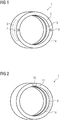
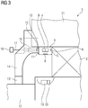
- the sensor unit 1 shown serves to monitor a transmission 3 or its components, in the present case for monitoring a transmission bearing 2, as will be described below with reference to FIG FIG 3 will be explained in more detail.
- the sensor unit 1 comprises an annular base body 4, which is preferably made additively from an oil-resistant and temperature- and pressure-resistant material, for example from polyamide.
- a measured variable transducer 6 of a temperature sensor device and a measured variable transducer 7 of a vibration sensor device are positioned or embedded in the end face 5 on a first end face 5 of the base body 4.
- the measured variable pick-up 6 of the temperature sensor device can be a thermocouple, for example.
- a MEMS sensor (Micro-Electro-Mechanical-System), for example, can be used as the measured variable pick-up 7 of the vibration sensor device.
- a signal receiver 8 is positioned on the inner circumference of the base body 4 as a sensor component of a torque sensor device, in the present case in the form of a ring-shaped signal receiver made from a brass band.
- the transducers 6 and 7 as well as the signal receiver 8 are connected to a circuit board 9, which in the present case is positioned inside the base body 4 and has the necessary voltage supply and signal transmission components for the said sensor components.
- the sensor unit 1 has a single externally accessible interface 10, which is wired to the circuit board 9 and is used to connect external voltage supply and signal transmission lines.
- the interface 10 is positioned on the end face 11 of the base body 4 opposite the end face 5.
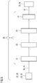
- FIG 3 shows an example of a region of a transmission 3 with a transmission housing 21 in which a transmission shaft 12 is rotatably held using transmission bearings 2, FIG FIG 3 only one of the gearbox bearings 2 is shown.
- a transmission housing cover 14 which is sealed off from the transmission shaft 12 by a seal 13, and the transmission bearing 2, the in the Figures 1 and 2
- the sensor unit 1 shown is mounted in such a way that the base body 4 rests firmly on the end face on both components and the transducers 6 and 7 of the temperature and vibration sensor devices point towards the gearbox bearing 2 to be monitored.
- the gear housing cover is provided with a recess 15 and a through-hole 16 axially aligned with the interface 10 to provide space for connecting and passing through FIG 3
- a voltage supply and signal evaluation device 18 On the transmission shaft 12, radially inward of the base body 4, as further sensor components of the torque sensor device, there are a measurement variable pick-up 19 and a signal transmitter 20 are provided, which in the present case are embedded in the transmission shaft 12.
- a significant advantage is that the measured variable transducers 6, 7 and the signal receiver 8 can be installed in a mechanical system, for example for sensor components of various sensor devices, with little expenditure of time and money, since they are arranged on a single base body 4.
- Another advantage is that the sensor unit 1, thanks to its individual interface 10, can also be quickly and easily connected to the external voltage supply and signal evaluation device 18.
- FIG 4 an embodiment of a wind power plant 22 according to the invention is shown in a sectional oblique view.
- the wind power plant 22 comprises a rotor 23 which can be set in rotation by the wind.
- the rotor 23 is connected in a torque-transmitting manner via a rotor shaft 24 to a gear 3 according to the invention designed as a planetary gear.
- the transmission 3 is in turn connected to a generator 25 in a torque-transmitting manner.
- the rotor shaft 24, the gear 3 and the generator 25 belong to a drive train 26, which is accommodated in a nacelle 27 of the wind turbine 22.
- the generator 25 has two, three or four pairs of poles.
- FIG 5 shows a schematic structure of a further embodiment of the drive train 26 according to the invention, which can be used in a wind power plant 22 (not shown in detail) or in an industrial application 28 (not shown in detail).
- the drive train 26 comprises a transmission 3 according to the invention, which is designed as a planetary gear, which is connected on the input side to a drive means 29 or a rotor 23 of the wind power plant 22 and to which a drive power 30 is supplied. In a wind power plant 22, this takes place by means of a rotor shaft 24.
- the transmission 3 in the present case comprises planetary stages 31, 32 and 33 as well as a spur gear stage 34, which are arranged one behind the other.
- the gear stages 31, 32, 33 and 34 emit an output power 35 to a generator 25 or a mechanical application 36.
- FIG 6 the structure of an embodiment of an industrial application 28 is shown schematically, which has a drive means 29.
- the drive means 29 is designed to provide a drive power 30 which is transported to a transmission 3 according to the invention through a torque-transmitting connection.
- the transmission 3 is in turn connected in a torque-transmitting manner to a mechanical application 36 in order to transport an output power 35 to the mechanical application 36.
Landscapes
- Engineering & Computer Science (AREA)
- Physics & Mathematics (AREA)
- General Physics & Mathematics (AREA)
- Life Sciences & Earth Sciences (AREA)
- Sustainable Energy (AREA)
- General Engineering & Computer Science (AREA)
- Sustainable Development (AREA)
- Chemical & Material Sciences (AREA)
- Mechanical Engineering (AREA)
- Combustion & Propulsion (AREA)
- Power Engineering (AREA)
- Manufacturing & Machinery (AREA)
- Materials Engineering (AREA)
- Arrangements For Transmission Of Measured Signals (AREA)
- Wind Motors (AREA)
- Testing Of Devices, Machine Parts, Or Other Structures Thereof (AREA)
- Rolling Contact Bearings (AREA)
Abstract
Description
- Die vorliegende Erfindung betrifft eine Sensoreinheit umfassend Sensorbestandteile verschiedener Sensoreinrichtungen sowie zumindest eine Spannungsversorgungs- und Signalübertragungskomponenten für diese Sensorbestandteile aufweisende Platine, an welche die Sensorbestandteile angeschlossen sind. Ferner betrifft die vorliegende Erfindung ein Getriebe mit zumindest einer solchen Sensoreinheit. Darüber hinaus betrifft die Erfindung einen Antriebsstrang mit einem solchen Getriebe, eine Windkraftanlage mit einem solchen Antriebsstrang sowie eine Industrie-Applikation mit einem solchen Getriebe.
- Es ist wünschenswert, mechanische Systeme, beispielsweise in Form von Getrieben, IoT-fähig zu gestalten (IoT: Internet of Things). Hierzu werden Sensoreinrichtungen verbaut, um Messgrößen wie Drehmomente, Drehzahlen, Schwingungen und Temperaturen aufzunehmen. Die Messgrößenaufnehmer der Sensoreinrichtungen werden im Falle eines Getriebes an verschiedenen Stellen am und im Getriebe montiert und dann mit einer oder mehreren Platinen verbunden, welche die erforderlichen Spannungsversorgungs- und Signalübertragungskomponenten für die entsprechenden Sensoren aufweisen. Die Platinen werden dann wiederum mit zumindest einer externen Spannungsversorgungs- und Signalauswerteeinrichtung verbunden. Diese Art der Verdrahtung zieht einen hohen Zeit- und Kostenaufwand nach sich.
- Ausgehend von diesem Stand der Technik ist es eine Aufgabe der vorliegenden Erfindung, eine Sensoreinheit mit alternativem Aufbau zu schaffen.
- Zur Lösung dieser Aufgabe schafft die vorliegende Erfindung eine Sensoreinheit, die dadurch gekennzeichnet ist, dass sie einen die Sensorbestandteile sowie die zumindest eine Platine aufnehmenden ringförmigen Basiskörper aufweist. Dank der Tatsache, dass Sensorbestandteile verschiedener Sensoreinrichtungen sowie die zumindest eine Platine, welche die Spannungsversorgungs- und Signalübertragungskomponenten für diese Sensorbestandteile aufweist, an einem einzelnen ringförmigen Basiskörper vormontiert und untereinander geeignet verdrahtet sind, lässt sich die erfindungsgemäße Sensoreinheit schnell und einfach in einem mechanischen System montieren, da lediglich der Basiskörper eingebaut werden muss. Entsprechend geht die Montage der erfindungsgemäßen Sensoreinheit mit geringem Zeit- und Kostenaufwand einher.
- Gemäß einer Ausgestaltung der vorliegenden Erfindung weisen die verschiedenen Sensoreinrichtungen zumindest eine Temperatursensoreinrichtung und/oder zumindest eine Drehmomentsensoreinrichtung und/oder zumindest eine Vibrationssensoreinrichtung auf. Damit können mit einer einzelnen Sensoreinheit sämtliche Daten aufgenommen werden, die insbesondere für die Überwachung eines Getriebes erforderlich sind.
- Bevorzugt ist an dem Basiskörper eine einzelne von außen zugängliche Schnittstelle zum Anschließen externer Spannungsversorgungs- und Signalübertragungsleitungen vorgesehen. Auf diese Weise wird die Handhabung einer erfindungsgemäßen Sensoreinheit bezüglich des Anschließens der Sensoreinheit an eine externe Spannungsversorgungs- und Signalauswerteeinrichtung deutlich verbessert.
- Vorteilhaft sind als Sensorbestandteile ein Messgrößenaufnehmer zumindest einer Temperatursensoreinrichtung und ein Messgrößenaufnehmer zumindest einer Vibrationssensoreinrichtung an einer ersten Stirnseite des Basiskörpers positioniert, und die Spannungsversorgungs- und Signalübertragungsschnittstelle ist an einer gegenüberliegenden zweiten Stirnseite des Basiskörpers positioniert. Entsprechend können die Messgrößenaufnehmer der Temperatursensor- und der Vibrationssensoreinrichtung bei der Montage des Basiskörpers zu einem zu überwachenden Bauteil ausgerichtet werden, bei dem es sich z.B. um ein Getriebelager handelt, während ein Anschließen externer Spannungsversorgungs- und Signalübertragungsleitungen von der anderen Stirnseite des Basiskörpers erfolgt.
- Als Sensorbestandteil einer Drehmomentsensoreinrichtung ist bevorzugt ein Signalempfänger am Innenumfang des Basiskörpers positioniert, insbesondere ein ringförmig ausgebildeter Signalempfänger, beispielsweise in Form eines Messingbandes oder dergleichen. Der zugehörige Messgrößenaufnehmer sowie der zugehörige Signalsender der Drehmomentsensoreinrichtung werden dann im Falle eines Getriebes an eine Getriebewelle radial einwärts des Basiskörpers positioniert.
- Gemäß einer Ausgestaltung der vorliegenden Erfindung ist die Platine im Innern des Basiskörpers positioniert. Ein Vorteil einer solchen Anordnung der Platine besteht darin, dass die Platine vor äußeren Einflüssen geschützt ist. Analoges gilt auch für die zwischen den Sensorbestandteilen und der Platine vorhandenen Verdrahtungen.
- Der Basiskörper ist vorteilhaft aus einem ölbeständigen, temperatur- und druckfesten Material hergestellt, insbesondere aus einem Kunststoff, bevorzugt aus Polyamid. Entsprechend kann der Basiskörper den in einem Getriebe bzw. in einem mechanischen System vorherrschenden Bedingungen ohne weiteres standhalten. Das Maß der Ölbeständigkeit sowie der Temperatur- und Druckfestigkeit des Materials ist jeweils anhand der Betriebsbedingungen des mechanischen Systems festzulegen, in welches die Sensoreinheit integriert wird.
- Gemäß einer Ausgestaltung der vorliegenden Erfindung ist der Basiskörper additiv gefertigt, was eine hohe Flexibilität bei der Produktion des Basiskörpers und damit auch der Sensoreinheit nach sich zieht. Alternativ ist es grundsätzlich natürlich auch möglich, den Basiskörper unter Einsatz anderer Fertigungstechnologien zu produzieren.
- Ferner schafft die vorliegende Erfindung Getriebe mit zumindest einer erfindungsgemäßen Sensoreinheit.
- Der Basiskörper der Sensoreinheit ist bevorzugt zwischen einem auf einer Getriebewelle angeordneten Getriebelager und einem Getriebegehäusedeckel angeordnet und kann an diesen Getriebekomponenten anliegen, insbesondere wenn diese Getriebekomponenten fokussiert betrachtet werden sollen.
- An der Getriebewelle sind bevorzugt radial einwärts des Basiskörpers als Sensorbestandteile einer Drehmomentsensoreinrichtung ein Messgrößenaufnehmer und ein Signalsender vorgesehen, der die vom Messgrößenaufnehmer erfassten Messdaten an einen am Innenumfang des Basiskörpers vorgesehenen Signalempfänger übermittelt.
- Ferner schafft die Erfindung einen Antriebsstrang, umfassend eine Rotorwelle, die drehmomentübertragend mit einem Getriebe verbunden ist, das wiederum drehmomentübertragend mit einem Generator verbunden ist, dadurch gekennzeichnet, dass das Getriebe als erfindungsgemäßes Getriebe ausgebildet ist.
- Zudem schafft die vorliegende Erfindung eine Windkraftanlage, umfassend einen Rotor, der an einer Gondel angebracht ist, wobei in der Gondel ein Antriebsstrang angeordnet ist, der drehmomentübertragend mit dem Rotor verbunden ist, wobei der Antriebsstrang als erfindungsgemäßer Antriebsstrang ausgebildet ist.
- Darüber hinaus schafft die vorliegende Erfindung eine Industrie-Applikation, umfassend ein Antriebsmittel, das mit einem Getriebe drehmomentübertragend verbunden ist, das mit einer mechanischen Anwendung drehmomentübertragend gekoppelt ist, wobei das Getriebe als erfindungsgemäßes Getriebe ausgebildet ist.
- Weitere Merkmale und Vorteile der vorliegenden Erfindung werden anhand der nachfolgenden Beschreibung unter Bezugnahme auf die beiliegende Zeichnung deutlich. Darin ist
- FIG 1
- eine perspektivische Vorderansicht einer Sensoreinheit gemäß einer Ausführungsform der vorliegenden Erfindung;
- FIG 2
- eine perspektivische Rückansicht der in
FIG 1 gezeigten Sensoreinheit; - FIG 3
- eine Teilschnittansicht eines Getriebes mit einer in den
Figuren 1 und 2 dargestellten Sensoreinheit; - FIG 4
- eine geschnittene Seitenansicht einer Ausführungsform einer erfindungsgemäßen Windkraftanlage;
- FIG 5
- eine schematische Darstellung einer Ausführungsform eines erfindungsgemäßen Antriebsstrangs und
- FIG 6
- eine schematische Darstellung einer Ausführungsform einer erfindungsgemäßen Industrie-Applikation.
- Die in den
Figuren 1 und 2 dargestellte Sensoreinheit 1 dient zur Überwachung eines Getriebes 3 oder seiner Komponenten, vorliegend zur Überwachung eines Getriebelagers 2, wie es nachfolgend unter Bezugnahme aufFIG 3 noch näher erläutert wird. Die Sensoreinheit 1 umfasst einen ringförmigen Basiskörper 4, der bevorzugt additiv aus einem ölbeständigen sowie temperatur- und druckfesten Material hergestellt ist, beispielsweise aus Polyamid. An einer ersten Stirnseite 5 des Basiskörpers 4 sind ein Messgrößenaufnehmer 6 einer Temperatursensoreinrichtung und ein Messgrößenaufnehmer 7 einer Vibrationssensoreinrichtung positioniert bzw. in die Stirnseite 5 eingelassen. Bei dem Messgrößenaufnehmer 6 der Temperatursensoreinrichtung kann es sich beispielsweise um ein Thermoelement handeln. Als Messgrößenaufnehmer 7 der Vibrationssensoreinrichtung kann zum Beispiel ein MEMS-Sensor (Micro-Electro-Mechanical-System) eingesetzt werden. Am Innenumfang des Basiskörpers 4 ist als Sensorbestandteil einer Drehmomentsensoreinrichtung ein Signalempfänger 8 positioniert, vorliegend in Form eines ringförmig ausgebildeten Signalempfängers aus einem Messingband. Die Messgrößenaufnehmer 6 und 7 sowie der Signalempfänger 8 sind an eine Platine 9 angeschlossen, die vorliegend im Inneren des Basiskörpers 4 positioniert ist und die erforderlichen Spannungsversorgungs- und Signalübertragungskomponenten für die besagten Sensorbestandteile aufweist. Ferner verfügt die Sensoreinheit 1 über eine einzelne von außen zugängliche Schnittstelle 10, die mit der Platine 9 verdrahtet ist und zum Anschließen externer Spannungsversorgungs- und Signalübertragungsleitungen dient. Die Schnittstelle 10 ist vorliegend an der der Stirnseite 5 gegenüberliegenden Stirnseite 11 des Basiskörpers 4 positioniert. -
FIG 3 zeigt beispielhaft einen Bereich eines Getriebes 3 mit einem Getriebegehäuse 21, in dem eine Getriebewelle 12 unter Verwendung von Getriebelagern 2 drehbar gehalten ist, wobei inFIG 3 nur eines der Getriebelager 2 dargestellt ist. Zwischen einem über eine Dichtung 13 gegenüber der Getriebewelle 12 abgedichteten Getriebegehäusedeckel 14 und dem Getriebelager 2 ist die in denFiguren 1 und 2 dargestellte Sensoreinheit 1 derart montiert, dass der Basiskörper 4 stirnseitig fest an beiden Bauteilen anliegt und die Messgrößenaufnehmer 6 und 7 der Temperatur- und Vibrationssensoreinrichtungen zu dem zu überwachenden Getriebelager 2 weisen. Im Bereich der Schnittstelle 10 ist der Getriebegehäusedeckel mit einer Aussparung 15 und einer axial mit der Schnittstelle 10 fluchtenden Durchgangsbohrung 16 versehen, um Platz zum Anschließen und Hindurchführen von inFIG 3 gestrichelt dargestellten Spannungsversorgungs- und Signalübertragungsleitungen 17 zu schaffen, über welche die Sensoreinheit 1 mit einer Spannungsversorgungs- und Signalauswerteeinrichtung 18 verbunden ist. An der Getriebewelle 12 sind radial einwärts des Basiskörpers 4 als weitere Sensorbestandteile der Drehmomentsensoreinrichtung ein Messgrößenaufnehmer 19 und ein Signalsender 20 vorgesehen, die vorliegend in die Getriebewelle 12 eingelassen sind. - Ein wesentlicher Vorteil besteht darin, dass sich die Messgrößenaufnehmer 6, 7 und der Signalempfänger 8 beispielhaft für Sensorkomponenten verschiedener Sensoreinrichtungen mit geringem Zeit- und Kostenaufwand in einem mechanischen System montieren lassen, da diese an einem einzelnen Basiskörper 4 angeordnet sind. Ein weiterer Vorteil besteht darin, dass sich die Sensoreinheit 1 Dank ihrer einzelnen Schnittstelle 10 auch schnell einfach an die externe Spannungsversorgungs- und Signalauswerteeinrichtung 18 anschließen lässt.
- In
FIG 4 ist in einer geschnittenen Schrägansicht eine Ausführungsform einer erfindungsgemäßen Windkraftanlage 22 dargestellt. Die Windkraftanlage 22 umfasst eine Rotor 23, der durch Wind in Drehung versetzbar ist. Der Rotor 23 ist über eine Rotorwelle 24 mit einem als Planetengetriebe ausgeführten erfindungsgemäßen Getriebe 3 drehmomentübertragend verbunden. Das Getriebe 3 wiederum ist drehmomentübertragend mit einem Generator 25 verbunden. Die Rotorwelle 24, das Getriebe 3 und der Generator 25 gehören zu einem Antriebsstrang 26, der in einer Gondel 27 der Windkraftanlage 22 aufgenommen ist. Der Generator 25 weist zwei, drei oder vier Polpaare auf. -
FIG 5 zeigt einen schematischen Aufbau einer weiteren Ausführungsform des erfindungsgemäßen Antriebsstrangs 26, der in einer nicht näher dargestellten Windkraftanlage 22 oder einer nicht näher dargestellten Industrie-Applikation 28 einsetzbar ist. Der Antriebsstrang 26 umfasst ein erfindungsgemäßes Getriebe 3, das als Planetengetriebe ausgeführt ist, das eingangsseitig mit einem Antriebsmittel 29 oder einem Rotor 23 der Windkraftanlage 22 verbunden ist und dem so eine Antriebsleistung 30 zugeführt wird. In einer Windkraftanlage 22 erfolgt dies mittels einer Rotorwelle 24. Das Getriebe 3 umfasst vorliegend Planetenstufen 31, 32 und 33 sowie eine Stirnradstufe 34, die hintereinander angeordnet sind. Die Getriebestufen 31, 32, 33 und 34 geben eine Abtriebsleistung 35 an einen Generator 25 oder eine mechanische Anwendung 36 ab. - In
FIG 6 ist schematisch der Aufbau einer Ausführungsform einer Industrie-Applikation 28 dargestellt, die über ein Antriebsmittel 29 verfügt. Das Antriebsmittel 29 ist dazu ausgebildet, eine Antriebsleistung 30 bereitzustellen, die durch eine drehmomentübertragende Verbindung an ein erfindungsgemäßes Getriebe 3 transportiert wird. Das Getriebe 3 ist wiederum drehmomentübertragend mit einer mechanischen Anwendung 36 verbunden, um eine Abtriebsleistung 35 zur mechanischen Anwendung 36 zu transportieren. - Obwohl die Erfindung im Detail durch das bevorzugte Ausführungsbeispiel näher illustriert und beschrieben wurde, so ist die Erfindung nicht durch die offenbarten Beispiele eingeschränkt und andere Variationen können vom Fachmann hieraus abgeleitet werden, ohne den Schutzumfang der Erfindung zu verlassen.
Claims (14)
- Sensoreinheit (1) umfassend Sensorbestandteile verschiedener Sensoreinrichtungen sowie zumindest eine Spannungsversorgungs- und Signalübertragungskomponenten für diese Sensorbestandteile aufweisende Platine (9), an welche die Sensorbestandteile angeschlossen sind, dadurch gekennzeichnet, dass die Sensoreinheit (1) einen die Sensorbestandteile sowie die zumindest eine Platine (9) aufnehmenden ringförmigen Basiskörper (4) aufweist.
- Sensoreinheit (1) nach Anspruch 1, dadurch gekennzeichnet, dass die verschiedenen Sensoreinrichtungen zumindest eine Temperatursensoreinrichtung und/oder zumindest eine Drehmomentsensoreinrichtung und/oder zumindest eine Vibrationssensoreinrichtung aufweisen.
- Sensoreinheit (1) nach Anspruch 1 oder 2, dadurch gekennzeichnet, dass an dem Basiskörper (4) eine einzelne von außen zugängliche Schnittstelle (10) zum Anschließen externer Spannungsversorgungs- und Signalübertragungsleitungen (17) vorgesehen ist.
- Sensoreinheit (1) nach Anspruch 3, dadurch gekennzeichnet, dass als Sensorbestandteile ein Messgrößenaufnehmer (6) zumindest einer Temperatursensoreinrichtung und ein Messgrößenaufnehmer (7) zumindest einer Vibrationssensoreinrichtung an einer ersten Stirnseite (5) des Basiskörpers (4) positioniert sind, und dass die Spannungsversorgungs- und Signalübertragungsschnittstelle (10) an einer gegenüberliegenden zweiten Stirnseite (11) des Basiskörpers (4) positioniert ist.
- Sensoreinheit (1) nach einem der Ansprüche 2 bis 4, dadurch gekennzeichnet, dass als Sensorbestandteil einer Drehmomentsensoreinrichtung ein Signalempfänger (8) am Innenumfang des Basiskörpers (4) positioniert ist, insbesondere ein ringförmig ausgebildeter Signalempfänger (8).
- Sensoreinheit (1) nach einem der vorhergehenden Ansprüche, dadurch gekennzeichnet, dass die Platine (9) im Innern des Basiskörpers (4) positioniert ist.
- Sensoreinheit (1) nach einem der vorhergehenden Ansprüche, dadurch gekennzeichnet, dass der Basiskörper (4) aus einem ölbeständigen, temperatur- und druckfesten Material hergestellt ist, insbesondere aus einem Kunststoff, bevorzugt aus Polyamid.
- Sensoreinheit (1) nach einem der vorhergehenden Ansprüche, dadurch gekennzeichnet, dass der Basiskörper (4) additiv gefertigt ist.
- Getriebe (3) mit zumindest einer Sensoreinheit (1) nach einem der vorhergehenden Ansprüche.
- Getriebe (3) nach Anspruch 9, dadurch gekennzeichnet, dass der Basiskörper (4) der Sensoreinheit (1) zwischen einem auf einer Getriebewelle (12) angeordneten Getriebelager (2) und einem Getriebegehäusedeckel (14) angeordnet ist und insbesondere an diesen Getriebekomponenten anliegt.
- Getriebe (3) nach Anspruch 10, dadurch gekennzeichnet, dass an der Getriebewelle (12) radial einwärts des Basiskörpers (4) als Sensorbestandteile einer Drehmomentsensoreinrichtung ein Messgrößenaufnehmer (19) und ein Signalsender (20) vorgesehen sind.
- Antriebsstrang (26), umfassend eine Rotorwelle (24), die drehmomentübertragend mit einem Getriebe (3) verbunden ist, das wiederum drehmomentübertragend mit einem Generator (25) verbunden ist, dadurch gekennzeichnet, dass das Getriebe (3) nach einem der Ansprüche 9 bis 11 ausgebildet ist.
- Windkraftanlage (22), umfassend einen Rotor (23), der an einer Gondel (27) angebracht ist, wobei in der Gondel (27) ein Antriebsstrang (26) angeordnet ist, der drehmomentübertragend mit dem Rotor (23) verbunden ist, dadurch gekennzeichnet, dass der Antriebsstrang (26) nach Anspruch 12 ausgebildet ist.
- Industrie-Applikation (28), umfassend ein Antriebsmittel (29), das mit einem Getriebe (3) drehmomentübertragend verbunden ist, das mit einer mechanischen Anwendung (36) drehmomentübertragend gekoppelt ist, dadurch gekennzeichnet, dass das Getriebe (3) nach einem der Ansprüche 9 bis 11 ausgebildet ist.
Priority Applications (6)
| Application Number | Priority Date | Filing Date | Title |
|---|---|---|---|
| ES19194547T ES2933955T3 (es) | 2019-08-30 | 2019-08-30 | Unidad de sensor y engranaje con al menos una unidad de sensor de este tipo |
| FIEP19194547.6T FI3786591T3 (fi) | 2019-08-30 | 2019-08-30 | Anturiyksikkö ja vaihteisto ainakin yhden sellaisen anturiyksikön kera |
| EP19194547.6A EP3786591B1 (de) | 2019-08-30 | 2019-08-30 | Sensoreinheit und getriebe mit zumindest einer solchen sensoreinheit |
| US17/005,289 US11754052B2 (en) | 2019-08-30 | 2020-08-27 | Sensor unit and gear having at least one such unit |
| CN202010888306.0A CN112444287B (zh) | 2019-08-30 | 2020-08-28 | 传感器单元和具有至少一个这种传感器单元的传动装置 |
| BR102020017664A BR102020017664A8 (pt) | 2019-08-30 | 2020-08-28 | Engrenagem, unidade sensora, trem de acionamento, instalação de energia eólica, e, aplicação industrial. |
Applications Claiming Priority (1)
| Application Number | Priority Date | Filing Date | Title |
|---|---|---|---|
| EP19194547.6A EP3786591B1 (de) | 2019-08-30 | 2019-08-30 | Sensoreinheit und getriebe mit zumindest einer solchen sensoreinheit |
Publications (2)
| Publication Number | Publication Date |
|---|---|
| EP3786591A1 true EP3786591A1 (de) | 2021-03-03 |
| EP3786591B1 EP3786591B1 (de) | 2022-11-02 |
Family
ID=67810436
Family Applications (1)
| Application Number | Title | Priority Date | Filing Date |
|---|---|---|---|
| EP19194547.6A Active EP3786591B1 (de) | 2019-08-30 | 2019-08-30 | Sensoreinheit und getriebe mit zumindest einer solchen sensoreinheit |
Country Status (6)
| Country | Link |
|---|---|
| US (1) | US11754052B2 (de) |
| EP (1) | EP3786591B1 (de) |
| CN (1) | CN112444287B (de) |
| BR (1) | BR102020017664A8 (de) |
| ES (1) | ES2933955T3 (de) |
| FI (1) | FI3786591T3 (de) |
Cited By (1)
| Publication number | Priority date | Publication date | Assignee | Title |
|---|---|---|---|---|
| EP4266485A1 (de) | 2022-04-19 | 2023-10-25 | Flender GmbH | Statorantennen-einheit für eine messanordnung |
Citations (7)
| Publication number | Priority date | Publication date | Assignee | Title |
|---|---|---|---|---|
| US20030030565A1 (en) * | 2001-08-07 | 2003-02-13 | Nsk Ltd. | Wireless sensor, rolling bearing with sensor, management apparatus and monitoring system |
| JP2003065835A (ja) * | 2001-08-21 | 2003-03-05 | Nsk Ltd | センサ付軸受装置 |
| EP1292831A2 (de) * | 2000-06-23 | 2003-03-19 | The Timken Company | Lager mit drahtloser, sich selbstversorgender sensoreinheit |
| DE112014000688T5 (de) * | 2013-02-06 | 2015-10-22 | Schaeffler Technologies AG & Co. KG | Drehmomentsensor-Lageranordnung und Verfahren |
| CN204881845U (zh) * | 2015-08-13 | 2015-12-16 | 华北电力大学 | 一种基于stm的多通道风电机组振动数据采集系统 |
| EP3150978A1 (de) * | 2015-09-29 | 2017-04-05 | General Electric Company | System und verfahren zum messen der betriebsbedingung einer maschine |
| US20180224306A1 (en) * | 2016-06-02 | 2018-08-09 | Jason Patrick Wimmer | Wireless sensor system |
Family Cites Families (12)
| Publication number | Priority date | Publication date | Assignee | Title |
|---|---|---|---|---|
| CN1168965C (zh) * | 2002-07-22 | 2004-09-29 | 华南理工大学 | 汽车行驶工况驱动功率值测试系统及其测试方法 |
| DE102008013059B4 (de) | 2008-03-06 | 2017-12-14 | Sew-Eurodrive Gmbh & Co Kg | System mit Getriebe |
| EP2689164B1 (de) * | 2011-03-22 | 2015-01-07 | Aktiebolaget SKF | Getriebe mit vibrationssensor |
| CN102223044B (zh) * | 2011-06-08 | 2013-03-20 | 天津大学 | 一种转子电流可测式无刷双馈电机 |
| DE102012015654A1 (de) | 2012-08-09 | 2014-05-15 | Imo Holding Gmbh | Verfahren und Vorrichtung zur Erkennung und Überwachung des Zustands von Baugruppen und Komponenten. |
| CN202994344U (zh) * | 2012-09-20 | 2013-06-12 | 王建钧 | 自带转矩传感器的机电设备 |
| DK3034872T3 (da) | 2013-08-12 | 2019-05-13 | Jtekt Corp | Vindenergi-genereringsapparat udstyret med en rotations-overførselsindretning |
| GB2526543A (en) | 2014-05-26 | 2015-12-02 | Skf Ab | Wireless sensor module |
| DE102015000928B3 (de) | 2015-01-28 | 2016-07-21 | Thyssenkrupp Ag | Vorrichtung zur Einbringung eines Hilfsdrehmoments in eine Lenkwelle einer elektromechanischen Hilfskraftlenkung |
| CN204514377U (zh) | 2015-03-31 | 2015-07-29 | 海安县兰菱机电设备有限公司 | 汽油发电机测试装置 |
| EP3351830B2 (de) | 2017-01-23 | 2023-03-15 | Flender GmbH | Planetengetriebe mit verbesserter planetenträgerlagerung |
| DE102020132081A1 (de) * | 2020-12-03 | 2022-06-09 | Schaeffler Technologies AG & Co. KG | Sensoreinheit zur Ausbildung eines Sensorknotens in einem drahtlosen Sensornetzwerk und drahtloses Sensornetzwerk umfassend einen solchen Sensorknoten |
-
2019
- 2019-08-30 FI FIEP19194547.6T patent/FI3786591T3/fi active
- 2019-08-30 EP EP19194547.6A patent/EP3786591B1/de active Active
- 2019-08-30 ES ES19194547T patent/ES2933955T3/es active Active
-
2020
- 2020-08-27 US US17/005,289 patent/US11754052B2/en active Active
- 2020-08-28 BR BR102020017664A patent/BR102020017664A8/pt not_active Application Discontinuation
- 2020-08-28 CN CN202010888306.0A patent/CN112444287B/zh active Active
Patent Citations (7)
| Publication number | Priority date | Publication date | Assignee | Title |
|---|---|---|---|---|
| EP1292831A2 (de) * | 2000-06-23 | 2003-03-19 | The Timken Company | Lager mit drahtloser, sich selbstversorgender sensoreinheit |
| US20030030565A1 (en) * | 2001-08-07 | 2003-02-13 | Nsk Ltd. | Wireless sensor, rolling bearing with sensor, management apparatus and monitoring system |
| JP2003065835A (ja) * | 2001-08-21 | 2003-03-05 | Nsk Ltd | センサ付軸受装置 |
| DE112014000688T5 (de) * | 2013-02-06 | 2015-10-22 | Schaeffler Technologies AG & Co. KG | Drehmomentsensor-Lageranordnung und Verfahren |
| CN204881845U (zh) * | 2015-08-13 | 2015-12-16 | 华北电力大学 | 一种基于stm的多通道风电机组振动数据采集系统 |
| EP3150978A1 (de) * | 2015-09-29 | 2017-04-05 | General Electric Company | System und verfahren zum messen der betriebsbedingung einer maschine |
| US20180224306A1 (en) * | 2016-06-02 | 2018-08-09 | Jason Patrick Wimmer | Wireless sensor system |
Cited By (3)
| Publication number | Priority date | Publication date | Assignee | Title |
|---|---|---|---|---|
| EP4266485A1 (de) | 2022-04-19 | 2023-10-25 | Flender GmbH | Statorantennen-einheit für eine messanordnung |
| WO2023202874A1 (de) | 2022-04-19 | 2023-10-26 | Flender Gmbh | Statorantennen-einheit für eine messanordnung |
| US12519205B2 (en) | 2022-04-19 | 2026-01-06 | Flender Gmbh | Stator antenna unit for a measuring arrangement |
Also Published As
| Publication number | Publication date |
|---|---|
| BR102020017664A8 (pt) | 2023-05-09 |
| CN112444287A (zh) | 2021-03-05 |
| EP3786591B1 (de) | 2022-11-02 |
| CN112444287B (zh) | 2024-04-30 |
| FI3786591T3 (fi) | 2023-01-31 |
| US11754052B2 (en) | 2023-09-12 |
| ES2933955T3 (es) | 2023-02-15 |
| BR102020017664A2 (pt) | 2021-03-16 |
| US20210062793A1 (en) | 2021-03-04 |
Similar Documents
| Publication | Publication Date | Title |
|---|---|---|
| DE102019206169A1 (de) | Verfahren zur Überwachung eines Riementriebs | |
| DE2301102B2 (de) | Anordnung eines Drehschwingungsdämpfers zur Unterdrückung von Schwingungen im Antriebsstrang eines Kraftfahrzeugs | |
| DE202016106888U1 (de) | Vorrichtung zur Zustandsüberwachung | |
| DE102014105678A1 (de) | Sensorpaketierung auf der abtriebsseite von vorderradantriebgetrieben | |
| EP3081831B2 (de) | Planetengetriebe | |
| DE102014202425B4 (de) | Planetengetriebe mit einem integrierten Geberelement für eine Drehzahlmessung | |
| DE102011011012A1 (de) | Radnabenantrieb | |
| EP3786591B1 (de) | Sensoreinheit und getriebe mit zumindest einer solchen sensoreinheit | |
| DE102013224654B4 (de) | Antriebssystem für Schienenfahrzeuge mit elastischer Kupplung | |
| DE102017221372A1 (de) | Hybridgetriebe für ein Kraftfahrzeug | |
| EP3476026B1 (de) | Baukastensystem zur herstellung von antrieben, mit einer getriebeeinheit, einer elektrischen motoreinheit und einer elektronikeinheit | |
| DE102017128448A1 (de) | Differenzialgetriebe | |
| EP2295274A1 (de) | Antriebseinheit für ein Kraftfahrzeug | |
| DE102021119221A1 (de) | Elektrische Maschine zur Erzeugung elektrischer Energie und hybride Antriebseinheit für ein Fahrzeug | |
| DE102015223067A1 (de) | Getriebeanordnung zur achsparallelen Übertragung einer Antriebsleistung | |
| DE102017106311A1 (de) | Wechselflansch mit Sensorik für ein Getriebe | |
| DE102016221127A1 (de) | Antriebsanordnung für einen Hubschrauber mit Mittel zur Zustandsüberwachung | |
| DE102007058918A1 (de) | Getriebe | |
| DE102016125055A1 (de) | Schwungscheibe mit angeformtem Geberrad | |
| EP1719238B1 (de) | Elektrische antriebseinheit | |
| DE10236560B4 (de) | Mehrfach-Umdrehungszähler und Verfahren zu dessen Montage | |
| DE102017209363A1 (de) | Radsatzgetriebe für ein Schienenfahrzeug | |
| DE102016121787A1 (de) | Bolzenabdeckung | |
| DE102024101647A1 (de) | Getriebemodul | |
| DE102014212684A1 (de) | Sensortretlager |
Legal Events
| Date | Code | Title | Description |
|---|---|---|---|
| PUAI | Public reference made under article 153(3) epc to a published international application that has entered the european phase |
Free format text: ORIGINAL CODE: 0009012 |
|
| STAA | Information on the status of an ep patent application or granted ep patent |
Free format text: STATUS: THE APPLICATION HAS BEEN PUBLISHED |
|
| AK | Designated contracting states |
Kind code of ref document: A1 Designated state(s): AL AT BE BG CH CY CZ DE DK EE ES FI FR GB GR HR HU IE IS IT LI LT LU LV MC MK MT NL NO PL PT RO RS SE SI SK SM TR |
|
| AX | Request for extension of the european patent |
Extension state: BA ME |
|
| STAA | Information on the status of an ep patent application or granted ep patent |
Free format text: STATUS: REQUEST FOR EXAMINATION WAS MADE |
|
| 17P | Request for examination filed |
Effective date: 20210830 |
|
| RBV | Designated contracting states (corrected) |
Designated state(s): AL AT BE BG CH CY CZ DE DK EE ES FI FR GB GR HR HU IE IS IT LI LT LU LV MC MK MT NL NO PL PT RO RS SE SI SK SM TR |
|
| GRAP | Despatch of communication of intention to grant a patent |
Free format text: ORIGINAL CODE: EPIDOSNIGR1 |
|
| STAA | Information on the status of an ep patent application or granted ep patent |
Free format text: STATUS: GRANT OF PATENT IS INTENDED |
|
| INTG | Intention to grant announced |
Effective date: 20220803 |
|
| GRAS | Grant fee paid |
Free format text: ORIGINAL CODE: EPIDOSNIGR3 |
|
| GRAA | (expected) grant |
Free format text: ORIGINAL CODE: 0009210 |
|
| STAA | Information on the status of an ep patent application or granted ep patent |
Free format text: STATUS: THE PATENT HAS BEEN GRANTED |
|
| AK | Designated contracting states |
Kind code of ref document: B1 Designated state(s): AL AT BE BG CH CY CZ DE DK EE ES FI FR GB GR HR HU IE IS IT LI LT LU LV MC MK MT NL NO PL PT RO RS SE SI SK SM TR |
|
| REG | Reference to a national code |
Ref country code: GB Ref legal event code: FG4D Free format text: NOT ENGLISH |
|
| REG | Reference to a national code |
Ref country code: CH Ref legal event code: EP Ref country code: AT Ref legal event code: REF Ref document number: 1529054 Country of ref document: AT Kind code of ref document: T Effective date: 20221115 |
|
| REG | Reference to a national code |
Ref country code: DE Ref legal event code: R096 Ref document number: 502019006101 Country of ref document: DE |
|
| REG | Reference to a national code |
Ref country code: IE Ref legal event code: FG4D Free format text: LANGUAGE OF EP DOCUMENT: GERMAN |
|
| REG | Reference to a national code |
Ref country code: FI Ref legal event code: FGE |
|
| REG | Reference to a national code |
Ref country code: ES Ref legal event code: FG2A Ref document number: 2933955 Country of ref document: ES Kind code of ref document: T3 Effective date: 20230215 |
|
| REG | Reference to a national code |
Ref country code: LT Ref legal event code: MG9D |
|
| REG | Reference to a national code |
Ref country code: NL Ref legal event code: MP Effective date: 20221102 |
|
| PG25 | Lapsed in a contracting state [announced via postgrant information from national office to epo] |
Ref country code: SE Free format text: LAPSE BECAUSE OF FAILURE TO SUBMIT A TRANSLATION OF THE DESCRIPTION OR TO PAY THE FEE WITHIN THE PRESCRIBED TIME-LIMIT Effective date: 20221102 Ref country code: PT Free format text: LAPSE BECAUSE OF FAILURE TO SUBMIT A TRANSLATION OF THE DESCRIPTION OR TO PAY THE FEE WITHIN THE PRESCRIBED TIME-LIMIT Effective date: 20230302 Ref country code: NO Free format text: LAPSE BECAUSE OF FAILURE TO SUBMIT A TRANSLATION OF THE DESCRIPTION OR TO PAY THE FEE WITHIN THE PRESCRIBED TIME-LIMIT Effective date: 20230202 Ref country code: LT Free format text: LAPSE BECAUSE OF FAILURE TO SUBMIT A TRANSLATION OF THE DESCRIPTION OR TO PAY THE FEE WITHIN THE PRESCRIBED TIME-LIMIT Effective date: 20221102 |
|
| PG25 | Lapsed in a contracting state [announced via postgrant information from national office to epo] |
Ref country code: RS Free format text: LAPSE BECAUSE OF FAILURE TO SUBMIT A TRANSLATION OF THE DESCRIPTION OR TO PAY THE FEE WITHIN THE PRESCRIBED TIME-LIMIT Effective date: 20221102 Ref country code: PL Free format text: LAPSE BECAUSE OF FAILURE TO SUBMIT A TRANSLATION OF THE DESCRIPTION OR TO PAY THE FEE WITHIN THE PRESCRIBED TIME-LIMIT Effective date: 20221102 Ref country code: LV Free format text: LAPSE BECAUSE OF FAILURE TO SUBMIT A TRANSLATION OF THE DESCRIPTION OR TO PAY THE FEE WITHIN THE PRESCRIBED TIME-LIMIT Effective date: 20221102 Ref country code: IS Free format text: LAPSE BECAUSE OF FAILURE TO SUBMIT A TRANSLATION OF THE DESCRIPTION OR TO PAY THE FEE WITHIN THE PRESCRIBED TIME-LIMIT Effective date: 20230302 Ref country code: HR Free format text: LAPSE BECAUSE OF FAILURE TO SUBMIT A TRANSLATION OF THE DESCRIPTION OR TO PAY THE FEE WITHIN THE PRESCRIBED TIME-LIMIT Effective date: 20221102 Ref country code: GR Free format text: LAPSE BECAUSE OF FAILURE TO SUBMIT A TRANSLATION OF THE DESCRIPTION OR TO PAY THE FEE WITHIN THE PRESCRIBED TIME-LIMIT Effective date: 20230203 |
|
| PG25 | Lapsed in a contracting state [announced via postgrant information from national office to epo] |
Ref country code: NL Free format text: LAPSE BECAUSE OF FAILURE TO SUBMIT A TRANSLATION OF THE DESCRIPTION OR TO PAY THE FEE WITHIN THE PRESCRIBED TIME-LIMIT Effective date: 20221102 |
|
| PG25 | Lapsed in a contracting state [announced via postgrant information from national office to epo] |
Ref country code: SM Free format text: LAPSE BECAUSE OF FAILURE TO SUBMIT A TRANSLATION OF THE DESCRIPTION OR TO PAY THE FEE WITHIN THE PRESCRIBED TIME-LIMIT Effective date: 20221102 Ref country code: RO Free format text: LAPSE BECAUSE OF FAILURE TO SUBMIT A TRANSLATION OF THE DESCRIPTION OR TO PAY THE FEE WITHIN THE PRESCRIBED TIME-LIMIT Effective date: 20221102 Ref country code: EE Free format text: LAPSE BECAUSE OF FAILURE TO SUBMIT A TRANSLATION OF THE DESCRIPTION OR TO PAY THE FEE WITHIN THE PRESCRIBED TIME-LIMIT Effective date: 20221102 Ref country code: DK Free format text: LAPSE BECAUSE OF FAILURE TO SUBMIT A TRANSLATION OF THE DESCRIPTION OR TO PAY THE FEE WITHIN THE PRESCRIBED TIME-LIMIT Effective date: 20221102 Ref country code: CZ Free format text: LAPSE BECAUSE OF FAILURE TO SUBMIT A TRANSLATION OF THE DESCRIPTION OR TO PAY THE FEE WITHIN THE PRESCRIBED TIME-LIMIT Effective date: 20221102 |
|
| REG | Reference to a national code |
Ref country code: DE Ref legal event code: R097 Ref document number: 502019006101 Country of ref document: DE |
|
| PG25 | Lapsed in a contracting state [announced via postgrant information from national office to epo] |
Ref country code: SK Free format text: LAPSE BECAUSE OF FAILURE TO SUBMIT A TRANSLATION OF THE DESCRIPTION OR TO PAY THE FEE WITHIN THE PRESCRIBED TIME-LIMIT Effective date: 20221102 Ref country code: AL Free format text: LAPSE BECAUSE OF FAILURE TO SUBMIT A TRANSLATION OF THE DESCRIPTION OR TO PAY THE FEE WITHIN THE PRESCRIBED TIME-LIMIT Effective date: 20221102 |
|
| PLBE | No opposition filed within time limit |
Free format text: ORIGINAL CODE: 0009261 |
|
| STAA | Information on the status of an ep patent application or granted ep patent |
Free format text: STATUS: NO OPPOSITION FILED WITHIN TIME LIMIT |
|
| 26N | No opposition filed |
Effective date: 20230803 |
|
| PG25 | Lapsed in a contracting state [announced via postgrant information from national office to epo] |
Ref country code: SI Free format text: LAPSE BECAUSE OF FAILURE TO SUBMIT A TRANSLATION OF THE DESCRIPTION OR TO PAY THE FEE WITHIN THE PRESCRIBED TIME-LIMIT Effective date: 20221102 |
|
| PG25 | Lapsed in a contracting state [announced via postgrant information from national office to epo] |
Ref country code: MC Free format text: LAPSE BECAUSE OF FAILURE TO SUBMIT A TRANSLATION OF THE DESCRIPTION OR TO PAY THE FEE WITHIN THE PRESCRIBED TIME-LIMIT Effective date: 20221102 |
|
| REG | Reference to a national code |
Ref country code: CH Ref legal event code: PL |
|
| PG25 | Lapsed in a contracting state [announced via postgrant information from national office to epo] |
Ref country code: MC Free format text: LAPSE BECAUSE OF FAILURE TO SUBMIT A TRANSLATION OF THE DESCRIPTION OR TO PAY THE FEE WITHIN THE PRESCRIBED TIME-LIMIT Effective date: 20221102 |
|
| PG25 | Lapsed in a contracting state [announced via postgrant information from national office to epo] |
Ref country code: LU Free format text: LAPSE BECAUSE OF NON-PAYMENT OF DUE FEES Effective date: 20230830 |
|
| GBPC | Gb: european patent ceased through non-payment of renewal fee |
Effective date: 20230830 |
|
| PG25 | Lapsed in a contracting state [announced via postgrant information from national office to epo] |
Ref country code: LU Free format text: LAPSE BECAUSE OF NON-PAYMENT OF DUE FEES Effective date: 20230830 Ref country code: CH Free format text: LAPSE BECAUSE OF NON-PAYMENT OF DUE FEES Effective date: 20230831 |
|
| REG | Reference to a national code |
Ref country code: IE Ref legal event code: MM4A |
|
| PG25 | Lapsed in a contracting state [announced via postgrant information from national office to epo] |
Ref country code: IE Free format text: LAPSE BECAUSE OF NON-PAYMENT OF DUE FEES Effective date: 20230830 |
|
| PG25 | Lapsed in a contracting state [announced via postgrant information from national office to epo] |
Ref country code: GB Free format text: LAPSE BECAUSE OF NON-PAYMENT OF DUE FEES Effective date: 20230830 |
|
| PG25 | Lapsed in a contracting state [announced via postgrant information from national office to epo] |
Ref country code: IE Free format text: LAPSE BECAUSE OF NON-PAYMENT OF DUE FEES Effective date: 20230830 Ref country code: GB Free format text: LAPSE BECAUSE OF NON-PAYMENT OF DUE FEES Effective date: 20230830 |
|
| PG25 | Lapsed in a contracting state [announced via postgrant information from national office to epo] |
Ref country code: BG Free format text: LAPSE BECAUSE OF FAILURE TO SUBMIT A TRANSLATION OF THE DESCRIPTION OR TO PAY THE FEE WITHIN THE PRESCRIBED TIME-LIMIT Effective date: 20221102 |
|
| PG25 | Lapsed in a contracting state [announced via postgrant information from national office to epo] |
Ref country code: BG Free format text: LAPSE BECAUSE OF FAILURE TO SUBMIT A TRANSLATION OF THE DESCRIPTION OR TO PAY THE FEE WITHIN THE PRESCRIBED TIME-LIMIT Effective date: 20221102 |
|
| PG25 | Lapsed in a contracting state [announced via postgrant information from national office to epo] |
Ref country code: CY Free format text: LAPSE BECAUSE OF FAILURE TO SUBMIT A TRANSLATION OF THE DESCRIPTION OR TO PAY THE FEE WITHIN THE PRESCRIBED TIME-LIMIT; INVALID AB INITIO Effective date: 20190830 |
|
| PG25 | Lapsed in a contracting state [announced via postgrant information from national office to epo] |
Ref country code: HU Free format text: LAPSE BECAUSE OF FAILURE TO SUBMIT A TRANSLATION OF THE DESCRIPTION OR TO PAY THE FEE WITHIN THE PRESCRIBED TIME-LIMIT; INVALID AB INITIO Effective date: 20190830 |
|
| PGFP | Annual fee paid to national office [announced via postgrant information from national office to epo] |
Ref country code: FI Payment date: 20250822 Year of fee payment: 7 Ref country code: ES Payment date: 20250926 Year of fee payment: 7 |
|
| PGFP | Annual fee paid to national office [announced via postgrant information from national office to epo] |
Ref country code: DE Payment date: 20250827 Year of fee payment: 7 |
|
| PGFP | Annual fee paid to national office [announced via postgrant information from national office to epo] |
Ref country code: IT Payment date: 20250825 Year of fee payment: 7 Ref country code: TR Payment date: 20250825 Year of fee payment: 7 |
|
| REG | Reference to a national code |
Ref country code: AT Ref legal event code: MM01 Ref document number: 1529054 Country of ref document: AT Kind code of ref document: T Effective date: 20240830 |
|
| PGFP | Annual fee paid to national office [announced via postgrant information from national office to epo] |
Ref country code: BE Payment date: 20250820 Year of fee payment: 7 |
|
| PG25 | Lapsed in a contracting state [announced via postgrant information from national office to epo] |
Ref country code: AT Free format text: LAPSE BECAUSE OF NON-PAYMENT OF DUE FEES Effective date: 20240830 |
|
| PGFP | Annual fee paid to national office [announced via postgrant information from national office to epo] |
Ref country code: FR Payment date: 20250828 Year of fee payment: 7 |
|
| PGFP | Annual fee paid to national office [announced via postgrant information from national office to epo] |
Ref country code: AT Payment date: 20260410 Year of fee payment: 5 |