EP3788209B1 - Method for making a virgin joint between two separate structural hollow sections, and such a virgin joint - Google Patents
Method for making a virgin joint between two separate structural hollow sections, and such a virgin joint Download PDFInfo
- Publication number
- EP3788209B1 EP3788209B1 EP19726201.7A EP19726201A EP3788209B1 EP 3788209 B1 EP3788209 B1 EP 3788209B1 EP 19726201 A EP19726201 A EP 19726201A EP 3788209 B1 EP3788209 B1 EP 3788209B1
- Authority
- EP
- European Patent Office
- Prior art keywords
- joint
- hollow sections
- structural hollow
- wrap
- virgin
- Prior art date
- Legal status (The legal status is an assumption and is not a legal conclusion. Google has not performed a legal analysis and makes no representation as to the accuracy of the status listed.)
- Active
Links
Images




Classifications
-
- E—FIXED CONSTRUCTIONS
- E04—BUILDING
- E04C—STRUCTURAL ELEMENTS; BUILDING MATERIALS
- E04C3/00—Structural elongated elements designed for load-supporting
- E04C3/02—Joists; Girders, trusses, or trusslike structures, e.g. prefabricated; Lintels; Transoms; Braces
- E04C3/04—Joists; Girders, trusses, or trusslike structures, e.g. prefabricated; Lintels; Transoms; Braces of metal
- E04C3/08—Joists; Girders, trusses, or trusslike structures, e.g. prefabricated; Lintels; Transoms; Braces of metal with apertured web, e.g. with a web consisting of bar-like components; Honeycomb girders
-
- E—FIXED CONSTRUCTIONS
- E04—BUILDING
- E04B—GENERAL BUILDING CONSTRUCTIONS; WALLS, e.g. PARTITIONS; ROOFS; FLOORS; CEILINGS; INSULATION OR OTHER PROTECTION OF BUILDINGS
- E04B1/00—Constructions in general; Structures which are not restricted either to walls, e.g. partitions, or floors or ceilings or roofs
- E04B1/18—Structures comprising elongated load-supporting parts, e.g. columns, girders, skeletons
- E04B1/19—Three-dimensional [3D] framework structures
- E04B1/1903—Connecting nodes specially adapted therefor
-
- E—FIXED CONSTRUCTIONS
- E02—HYDRAULIC ENGINEERING; FOUNDATIONS; SOIL SHIFTING
- E02B—HYDRAULIC ENGINEERING
- E02B17/00—Artificial islands mounted on piles or like supports, e.g. platforms on raisable legs or offshore constructions; Construction methods therefor
- E02B17/0004—Nodal points
-
- E—FIXED CONSTRUCTIONS
- E04—BUILDING
- E04B—GENERAL BUILDING CONSTRUCTIONS; WALLS, e.g. PARTITIONS; ROOFS; FLOORS; CEILINGS; INSULATION OR OTHER PROTECTION OF BUILDINGS
- E04B1/00—Constructions in general; Structures which are not restricted either to walls, e.g. partitions, or floors or ceilings or roofs
- E04B1/18—Structures comprising elongated load-supporting parts, e.g. columns, girders, skeletons
- E04B1/19—Three-dimensional [3D] framework structures
- E04B2001/1975—Frameworks where the struts are directly connected to each other, i.e. without interposed connecting nodes or plates
-
- E—FIXED CONSTRUCTIONS
- E04—BUILDING
- E04B—GENERAL BUILDING CONSTRUCTIONS; WALLS, e.g. PARTITIONS; ROOFS; FLOORS; CEILINGS; INSULATION OR OTHER PROTECTION OF BUILDINGS
- E04B1/00—Constructions in general; Structures which are not restricted either to walls, e.g. partitions, or floors or ceilings or roofs
- E04B1/18—Structures comprising elongated load-supporting parts, e.g. columns, girders, skeletons
- E04B1/24—Structures comprising elongated load-supporting parts, e.g. columns, girders, skeletons the supporting parts consisting of metal
- E04B1/2403—Connection details of the elongated load-supporting parts
- E04B2001/2451—Connections between closed section profiles
-
- E—FIXED CONSTRUCTIONS
- E04—BUILDING
- E04C—STRUCTURAL ELEMENTS; BUILDING MATERIALS
- E04C3/00—Structural elongated elements designed for load-supporting
- E04C3/02—Joists; Girders, trusses, or trusslike structures, e.g. prefabricated; Lintels; Transoms; Braces
- E04C3/04—Joists; Girders, trusses, or trusslike structures, e.g. prefabricated; Lintels; Transoms; Braces of metal
- E04C2003/0486—Truss like structures composed of separate truss elements
-
- E—FIXED CONSTRUCTIONS
- E04—BUILDING
- E04C—STRUCTURAL ELEMENTS; BUILDING MATERIALS
- E04C3/00—Structural elongated elements designed for load-supporting
- E04C3/02—Joists; Girders, trusses, or trusslike structures, e.g. prefabricated; Lintels; Transoms; Braces
- E04C3/04—Joists; Girders, trusses, or trusslike structures, e.g. prefabricated; Lintels; Transoms; Braces of metal
- E04C2003/0486—Truss like structures composed of separate truss elements
- E04C2003/0491—Truss like structures composed of separate truss elements the truss elements being located in one single surface or in several parallel surfaces
-
- E—FIXED CONSTRUCTIONS
- E04—BUILDING
- E04C—STRUCTURAL ELEMENTS; BUILDING MATERIALS
- E04C3/00—Structural elongated elements designed for load-supporting
- E04C3/02—Joists; Girders, trusses, or trusslike structures, e.g. prefabricated; Lintels; Transoms; Braces
- E04C3/28—Joists; Girders, trusses, or trusslike structures, e.g. prefabricated; Lintels; Transoms; Braces of materials not covered by groups E04C3/04 - E04C3/20
-
- E—FIXED CONSTRUCTIONS
- E04—BUILDING
- E04C—STRUCTURAL ELEMENTS; BUILDING MATERIALS
- E04C3/00—Structural elongated elements designed for load-supporting
- E04C3/02—Joists; Girders, trusses, or trusslike structures, e.g. prefabricated; Lintels; Transoms; Braces
- E04C3/29—Joists; Girders, trusses, or trusslike structures, e.g. prefabricated; Lintels; Transoms; Braces built-up from parts of different material, i.e. composite structures
-
- Y—GENERAL TAGGING OF NEW TECHNOLOGICAL DEVELOPMENTS; GENERAL TAGGING OF CROSS-SECTIONAL TECHNOLOGIES SPANNING OVER SEVERAL SECTIONS OF THE IPC; TECHNICAL SUBJECTS COVERED BY FORMER USPC CROSS-REFERENCE ART COLLECTIONS [XRACs] AND DIGESTS
- Y02—TECHNOLOGIES OR APPLICATIONS FOR MITIGATION OR ADAPTATION AGAINST CLIMATE CHANGE
- Y02E—REDUCTION OF GREENHOUSE GAS [GHG] EMISSIONS, RELATED TO ENERGY GENERATION, TRANSMISSION OR DISTRIBUTION
- Y02E10/00—Energy generation through renewable energy sources
- Y02E10/70—Wind energy
- Y02E10/72—Wind turbines with rotation axis in wind direction
-
- Y—GENERAL TAGGING OF NEW TECHNOLOGICAL DEVELOPMENTS; GENERAL TAGGING OF CROSS-SECTIONAL TECHNOLOGIES SPANNING OVER SEVERAL SECTIONS OF THE IPC; TECHNICAL SUBJECTS COVERED BY FORMER USPC CROSS-REFERENCE ART COLLECTIONS [XRACs] AND DIGESTS
- Y02—TECHNOLOGIES OR APPLICATIONS FOR MITIGATION OR ADAPTATION AGAINST CLIMATE CHANGE
- Y02E—REDUCTION OF GREENHOUSE GAS [GHG] EMISSIONS, RELATED TO ENERGY GENERATION, TRANSMISSION OR DISTRIBUTION
- Y02E10/00—Energy generation through renewable energy sources
- Y02E10/70—Wind energy
- Y02E10/727—Offshore wind turbines
Definitions
- the invention relates to a method for making a virgin joint between two separate structural hollow sections, and relates to such a virgin joint.
- the structural hollow sections are made of steel, but other materials are feasible as well.
- the invention is explicitly limited to the construction of a virgin joint, which is a newly made structural joint.
- Thin-walled circular or rectangular structural hollow sections are a cost effective solution for supporting lattice tower structures used for instance in Off-shore Wind Technology (OWT), oil platforms and in structural bridges.
- OHT Off-shore Wind Technology
- a disadvantage in case that steel or other metals are used for structural hollow sections is that the structures exhibit a relatively low fatigue endurance of the welded joints. The welding process reduces fatigue endurance of the structural hollow sections brace and chord members.
- the main structural problems are reduced fracture toughness of the material in the heat affected zone of the weld and stress concentration factors due to local notches, eccentricity of the weld and local deformation of thin-walled hollow sections.
- the welding costs are furthermore dominant in fabrication of steel jacket structures as for instance used for off-shore platform and wind turbines.
- thicker profiles need to be used to satisfy fatigue endurance driven design of such structures.
- HSS higher grade steels
- the safe and durable design is achieved by increasing the thickness of the base material or by improved welding technologies which generate high fabrication costs.
- US 2003/180570 A1 discloses a method for making a joint between at least two separate structural hollow sections in a truss / jacket structure.
- the invention proposes a method according to claim 1 for making a virgin joint between at least two separate structural hollow sections, wherein welding of the joint between the structural hollow sections is avoided, and wherein the joint is implemented by applying a fiber reinforced polymer wrap around the structural hollow sections in a transitional area covering and thus bonding together those portions of the structural hollow sections that together with the fiber reinforced polymer wrap form the joint between the structural hollow sections.
- the invention is also embodied in a virgin joint according to claim 9 between at least two separate hollow structural sections, wherein the joint excludes any weld and comprises a fiber reinforced polymer wrap around the structural hollow sections in a transitional area covering and thus bonding together those portions of the structural hollow sections that together with the fiber reinforced polymer wrap form the joint between the hollow structural sections.
- the forces between the structural hollow sections of the joint are transferred by adhesive bonding, friction and mechanical interlocking between the fiber reinforced polymer wrap and the outer surfaces of the structural hollow sections.
- the fiber reinforced polymer wrap therewith acts as a transition piece for the forces.
- the fiber reinforced polymer wrap is applied in a series of sequential lamination steps.
- the fiber reinforced polymer of the fiber reinforced polymer wrap is provided by mixing a thermoset resin matrix with fabrics and/or rovings of a fiber reinforcement.
- the fibre reinforcement can be embodied with glass fibres, carbon fibres, or similar, and the thermo-set resin matrix can be Unsaturated Polyester, Vinyl Ester, Epoxy or similar.
- the fiber reinforced polymer wrap has a length in the longitudinal direction of the structural hollow sections which is in the range of 0,5-5 times the diameter of the structural hollow sections.
- the quality of the joint between the at least two structural hollow sections is further promoted when the fiber reinforced polymer wrap has a thickness, measured transversely to the longitudinal direction of the structural hollow sections, in the range of 0.5-5 times the thickness of the structural hollow sections.
- the thickness of the FRP wrap is gradually reduced from a maximum thickness tW at the root of the joint towards the end of the FRP wrap as seen in the longitudinal direction of the structural hollow section in order to make a tapered joint, which reduces the stress concentrations at the adhesively bonded interface between the FRP wrap and the structural hollow section. For the same reason the transitions between the structural hollow sections at the root of the joint are made with a smooth geometry.
- Figure 1 shows a non-limiting general layout of a wrapped FRP joint - example of K-joint geometry in an truss/jacket structure made of structural hollow sections.
- the invention can be applied to any type of joint, such as K, X, T, N, KT, Y, joints, including combinations of those basic geometries, with gap and with overlap.
- the geometry is not limited to uniplanar but also multiplanar joints are covered, for example KK, TT, XX, YY.
- the joint can in particular be made between at least two separate structural hollow sections in a truss, lattice, jacket, space frame, space grid or any other form of multimember load carrying structure made of such structural hollow sections.
- Figure 1 illustrates the invention which concerns a Fibre Reinforced Polymer (FRP) joining technology to connect hollow section brace members 1 (diagonals) to chords 2 in joints 3.
- the diagonals 1 and the chords 2 are bonded together by the FRP wrap 4.
- An advantage of using FRP composite material to create a transition piece between the structural members 1, 2 is that it can be easily shaped in an optimal manner to reduce stress concentrations at the adhesively bonded interface.
- a very thin bondline is achieved by direct contact between the structural profiles 1, 2 and the FRP wrap 4 which reduces the risk of cohesive failure of the adhesive joint 3.
- the fatigue resistance of these sections is improved compared to welded joints.
- the corrosion critical region of the joint 3 of the structure is protected by the FRP wrap.
- FRP wrap Dimensions and geometry of the FRP wrap for the small-scale specimens were determined in a preliminary Finite Element Analysis (FEA), using nominal material properties of steel and FRP (given the fibre volume fraction and lay-up of reinforcement layers), and assumed bonding properties.
- FEA Finite Element Analysis
- the length of the overlap in the small-scale specimens varied in the range 140 - 240 mm, corresponding approximately to the range of 2-4 times the diameter of the steel structural hollow section brace member d SHS .
- the thickness t w varied in the range 7 - 14 mm which corresponds to 1.75-3.5 times the thickness of the steel structural hollow section brace member t SHS .
- Such ranges of the relative overlap length and thickness of the FRP wrap L w /d SHS and t W /t SHS , respectively, were chosen as assumed to be suitable for the case considered in the experiments where glass fibre reinforcement was used to form the wrapped FRP joint of mild steel structural hollow sections with certain slenderness, i.e.
- d SHS /t SHS 15.
- other types of fibre reinforcement of the FRP wrap such as carbon fibres, and other steel grades or materials used for the structural hollow sections, such as high-strength steels, and other d SHS /t SHS ratios of the structural hollow sections
- the ranges of the optimal relative length and thickness of the FRP wrap L w /d SHS and t W /t SHS shall be extended. It is assumed that for the variety of fibre reinforcements, materials and slenderness of structural hollow sections the optimal relative length and thickness of the FRP wrap L w /d SHS and t W /t SHS should lie in range of 0.5-5.
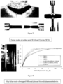
- Displacements due to an applied load were measured using LVDTs (Linear-Variable-Displacement-Transducers) at both sides of the joint, see Figure 4 , for all the specimens in order to be able to recognize any eccentric load transfer.
- LVDTs Linear-Variable-Displacement-Transducers
- Several specimens were instrumented with strain gauges oriented in the loading direction, placed on the outer surface of the FRP wrap and in some cases inside the steel structural hollow sections as shown in Figure 5 .
- strain gauges oriented in the loading direction, placed on the outer surface of the FRP wrap and in some cases inside the steel structural hollow sections as shown in Figure 5 .
- analysis of strain distributions along the joint and detection of slip due to imitation of bondline failure could be identified when a significant difference in the change of strain in the steel hollow section and the FRP wrap emerged.
- the strain measurements were also used for FEA validation of the experiments.
- the specimens failed at cross section between the splice (but weld) and the termination plate, as shown in the Figure 7 , because the strength of the welds with overmatching electrodes was much higher than the parent material.
- the force applied to the joint is normalized to the yield resistance of the brace member Fy and plotted against the relative displacement between the end points, excluding the termination plates. It may be concluded that the initial stiffness of the welded and wrapped FRP joints is similar. Very consistent results are obtained within three specimens of each series of wrapped FRP axial joints. Average ultimate resistances of 0.97Fy, 0.96Fy and 0.71Fy are achieved for A-240-14, A-240-7 and A-140-14 series, respectively. The conclusion is that the overlap length has a high influence on the ultimate resistance of the axial joint. The thickness however did not provide a high influence on the ultimate resistance.
- FIG. 9 Representative force displacement curves of wrapped axial specimens, the ones with minimum ultimate resistance, are compared in Figure 9 .
- Series A-240-14 show a distinctive change of stiffness at approx. 0.68Fy in Figure 9a which corresponds to an adhesive failure at the joint root.
- the initiation of adhesive failure is represented by a sudden increase of strains in the FRP and a decrease of strains in the structural hollow section, as shown in Figure 9b , meaning that slip occurred.
- Hardening is present between the stage of initiation of the bondline failure at the load level corresponding to 0.68Fy and final failure at 0.89Fy.
- a possible reason for such favourable behaviour may lie in the fact that the joint is axisymmetric.
- the circumferential tensile strains generated due to Pois-son's effects are larger in the FRP wrap than in the steel hollow section which results in confinement and at the bond interface. Compressive stresses due to confinement at the interface may provide additional slip resistance due to friction.
- Stiffness of the wrapped FRP X-joint is reduced compared to the axial wrapped FRP joint by approximately a factor 2.
- stiffens of the wrapped FRP X-joint compared to the welded X-joint is increased almost 3 times. This is due to reduced ovalisation of the chord member being stiffened by the FRP wrap.
- the elastic range of behaviour of a wrapped FRP X-joint is lower compared to the wrapped FRP axial joint.
- the initiation of adhesive bondline failure is obtained at range of 0.35Fy to 0.45Fy, which is in average 40% lower compared to axial specimens with a same thickness of the FRP wrap and overlap length (X-240-14 vs. A-240-14).
- Ductility on the other hand is increased approximately 92% compared to axial joints.
- Specimen X-240-14-2 was instrumented with strain gauges according to Figure 4 , to capture the strain development along the length of the joint. Gauges were put symmetrically away from the joint roots on both sides (front and back) of the specimen to reduce the effects of eccentricity in the monitored results.
- the adhesive crack can be identified at a load level of 0.83Fy. At 0.87Fy the ultimate resistance is reached by bottom brace member visibly slipping out of the FRP wrap.
Landscapes
- Engineering & Computer Science (AREA)
- Architecture (AREA)
- Civil Engineering (AREA)
- Structural Engineering (AREA)
- General Engineering & Computer Science (AREA)
- Composite Materials (AREA)
- Chemical & Material Sciences (AREA)
- Mechanical Engineering (AREA)
- Physics & Mathematics (AREA)
- Electromagnetism (AREA)
- Joining Of Building Structures In Genera (AREA)
- Working Measures On Existing Buildindgs (AREA)
- Lining Or Joining Of Plastics Or The Like (AREA)
Applications Claiming Priority (2)
| Application Number | Priority Date | Filing Date | Title |
|---|---|---|---|
| NL2020871A NL2020871B1 (en) | 2018-05-03 | 2018-05-03 | Method for making a virgin joint between two separate structural hollow sections, and such a virgin joint |
| PCT/NL2019/050245 WO2019212334A1 (en) | 2018-05-03 | 2019-04-26 | Method for making a virgin joint between two separate structural hollow sections, and such a virgin joint |
Publications (3)
| Publication Number | Publication Date |
|---|---|
| EP3788209A1 EP3788209A1 (en) | 2021-03-10 |
| EP3788209B1 true EP3788209B1 (en) | 2024-04-03 |
| EP3788209C0 EP3788209C0 (en) | 2024-04-03 |
Family
ID=62751512
Family Applications (1)
| Application Number | Title | Priority Date | Filing Date |
|---|---|---|---|
| EP19726201.7A Active EP3788209B1 (en) | 2018-05-03 | 2019-04-26 | Method for making a virgin joint between two separate structural hollow sections, and such a virgin joint |
Country Status (6)
| Country | Link |
|---|---|
| US (1) | US11542708B2 (pl) |
| EP (1) | EP3788209B1 (pl) |
| ES (1) | ES2978632T3 (pl) |
| NL (1) | NL2020871B1 (pl) |
| PL (1) | PL3788209T3 (pl) |
| WO (1) | WO2019212334A1 (pl) |
Families Citing this family (5)
| Publication number | Priority date | Publication date | Assignee | Title |
|---|---|---|---|---|
| US11919250B2 (en) * | 2021-08-25 | 2024-03-05 | The Boeing Company | Method of assembly of carbon fiber space frames for aerospace structures |
| KR102533316B1 (ko) * | 2022-11-29 | 2023-05-17 | (주)대창솔루션 | 주조에 의해 제조되는 해상풍력발전 하부 구조물용 노드 |
| NL2033721B1 (en) | 2022-12-14 | 2024-06-20 | Tree Composites Holding B V | Structural joint for use in an offshore supporting structure comprising an internal fibre reinforced polymer wrap |
| CN117432067B (zh) * | 2023-11-08 | 2024-06-18 | 江苏科能电力工程咨询有限公司 | 一种装配式复合材料桁架节点连接装置及连接方法 |
| NL2037527B1 (en) | 2024-04-24 | 2025-11-10 | Tree Composites Holding B V | Manufacturing process for a composite joint |
Citations (2)
| Publication number | Priority date | Publication date | Assignee | Title |
|---|---|---|---|---|
| US6585298B2 (en) * | 2001-11-13 | 2003-07-01 | Flowtite Technology As | High-strength butt-wrap joint for reinforced plastic pipes |
| US20030180570A1 (en) * | 2002-03-22 | 2003-09-25 | Cercone Lawrence D. | Method of repairing multiple tube structures and repaired multiple tube structures |
Family Cites Families (18)
| Publication number | Priority date | Publication date | Assignee | Title |
|---|---|---|---|---|
| US4504086A (en) * | 1983-01-10 | 1985-03-12 | Phillips Petroleum Company | Pipe tee |
| AU3375884A (en) * | 1983-10-07 | 1985-06-13 | Nagaoka Kanaami K.K. | Joint for tubular articles manufactured from different materials |
| US4671470A (en) * | 1985-07-15 | 1987-06-09 | Beech Aircraft Corporation | Method for fastening aircraft frame elements to sandwich skin panels covering same using woven fiber connectors |
| US5472290A (en) * | 1993-06-02 | 1995-12-05 | Altamont, Inc. | Joint with tapered edges |
| US5593744A (en) * | 1993-12-06 | 1997-01-14 | Oregon Reinforcement Engineering, Ltd. | Hollow reinforcing members and composites containing the same |
| US5732743A (en) * | 1996-06-14 | 1998-03-31 | Ls Technology Inc. | Method of sealing pipes |
| US6374570B1 (en) * | 2000-08-25 | 2002-04-23 | Lockheed Martin Corporation | Apparatus and method for joining dissimilar materials to form a structural support member |
| US6945727B2 (en) * | 2002-07-19 | 2005-09-20 | The Boeing Company | Apparatuses and methods for joining structural members, such as composite structural members |
| US20040074202A1 (en) * | 2002-10-22 | 2004-04-22 | Andrew Barmakian | Rod-reinforced cushion beam |
| US20050108980A1 (en) * | 2002-10-22 | 2005-05-26 | Andrew Barmakian | Rod-reinforced cushion beam |
| US20080302912A1 (en) * | 2007-06-08 | 2008-12-11 | The Boeing Company | Bladderless Mold Line Conformal Hat Stringer |
| ES2371951B1 (es) * | 2009-03-25 | 2012-11-21 | Airbus Operations, S.L. | Disposición de junta de elementos estructurales de un material compuesto. |
| AU2010236259B2 (en) * | 2009-04-16 | 2015-05-28 | Chevron U.S.A. Inc. | Structural components for oil, gas, exploration, refining and petrochemical applications |
| US20100266790A1 (en) * | 2009-04-16 | 2010-10-21 | Grzegorz Jan Kusinski | Structural Components for Oil, Gas, Exploration, Refining and Petrochemical Applications |
| US8074694B2 (en) * | 2009-05-28 | 2011-12-13 | The Boeing Company | Stringer transition method |
| US8522827B2 (en) * | 2009-10-06 | 2013-09-03 | Neptune Research, Inc. | Protective seal for pipeline assembly |
| US9162399B2 (en) * | 2010-09-22 | 2015-10-20 | Composite Rebat Technologies, Inc. | Hollow, composite-material rebar structure, associated components, and fabrication apparatus and methodology |
| US20160279865A1 (en) * | 2015-03-25 | 2016-09-29 | Milliken Infrastructure Solutions, Llc | Method and System of Joining at Least Two Tubular Members |
-
2018
- 2018-05-03 NL NL2020871A patent/NL2020871B1/en active
-
2019
- 2019-04-26 US US17/052,303 patent/US11542708B2/en active Active
- 2019-04-26 EP EP19726201.7A patent/EP3788209B1/en active Active
- 2019-04-26 ES ES19726201T patent/ES2978632T3/es active Active
- 2019-04-26 WO PCT/NL2019/050245 patent/WO2019212334A1/en not_active Ceased
- 2019-04-26 PL PL19726201.7T patent/PL3788209T3/pl unknown
Patent Citations (2)
| Publication number | Priority date | Publication date | Assignee | Title |
|---|---|---|---|---|
| US6585298B2 (en) * | 2001-11-13 | 2003-07-01 | Flowtite Technology As | High-strength butt-wrap joint for reinforced plastic pipes |
| US20030180570A1 (en) * | 2002-03-22 | 2003-09-25 | Cercone Lawrence D. | Method of repairing multiple tube structures and repaired multiple tube structures |
Also Published As
| Publication number | Publication date |
|---|---|
| NL2020871B1 (en) | 2019-11-12 |
| ES2978632T3 (es) | 2024-09-17 |
| US11542708B2 (en) | 2023-01-03 |
| WO2019212334A1 (en) | 2019-11-07 |
| EP3788209A1 (en) | 2021-03-10 |
| EP3788209C0 (en) | 2024-04-03 |
| PL3788209T3 (pl) | 2024-07-22 |
| US20210079651A1 (en) | 2021-03-18 |
Similar Documents
| Publication | Publication Date | Title |
|---|---|---|
| EP3788209B1 (en) | Method for making a virgin joint between two separate structural hollow sections, and such a virgin joint | |
| Dong et al. | Axial compressive behavior of square concrete columns reinforced with innovative closed-type winding GFRP stirrups | |
| Lesani et al. | Experimental investigation of FRP-strengthened tubular T-joints under axial compressive loads | |
| Ritchie et al. | Strengthening long steel columns of S-sections against global buckling around weak axis using CFRP plates of various moduli | |
| Chou et al. | Development and validation of a FRP-wrapped spiral corrugated tube for seismic performance of circular concrete columns | |
| Wu et al. | Torsional strengthening of steel circular hollow sections (CHS) using CFRP composites | |
| Yoresta et al. | Unbonded CFRP strengthening method for buckling control of steel members | |
| Park et al. | Flexural and compression behavior for steel structures strengthened with carbon fiber reinforced polymers (CFRPs) sheet | |
| Ulger et al. | Effect of initial panel slenderness on efficiency of strengthening-by-stiffening using FRP for shear deficient steel beams | |
| Alobaidi et al. | Structural strengthening of insufficiently designed reinforced concrete T-beams using CFRP composites | |
| Bruneau et al. | Cyclic testing of pultruded fiber-reinforced plastic beam-column rigid connection | |
| Belarbi et al. | Prestressing concrete with CFRP composites for sustainability and corrosion-free applications | |
| Komma et al. | Art-of-review on CFRP Wrapping to Strengthen Compressive and Flexural Behavior of Concrete. | |
| Hasibuan et al. | Enhancing Capacity and Ductility of Reinforced Concrete Column by Partially Wrapped Natural Fiber Reinforced Polymer | |
| Huang et al. | Concrete-encased steel columns confined with large rupture strain FRP composites: axial compression tests | |
| Sun et al. | Static and fatigue behavior of CFRP-strengthened RC bridge girders subjected to vehicle overloading | |
| Hamzenezhadi et al. | Flexural strengthening of deficient reinforced concrete beams with post-tensioned carbon composites using finite element modelling | |
| Rizkalla et al. | High modulus carbon fiber materials for retrofit of steel structures and bridges | |
| Wang et al. | Experimental research of FRP composite tube confined steel-reinforced concrete stub columns under axial compression | |
| Alam et al. | Experimental Investigation of FRP Strengthened Metal Tubular Members | |
| Limpaninlachat et al. | SHEAR PERFORMANCE OF REINFORCED CONCRETE BEAMS STRENGTHENED WITH AN INNOVATIVE EMBEDDED THROUGH-SECTION SYSTEM | |
| Maheswari et al. | EXPERIMENTAL INVESTIGATION ON HCS SECTION STRENGTHENED BY CARBON AND GLASS LAMINATES | |
| Khatir et al. | Experiences on Anchorage Systems for FRP | |
| Raftery et al. | Repair of glulam beams using GFRP rods | |
| Wu et al. | Seismic performance of RC columns strengthened with Dyneema fiber-reinforced polymer sheets |
Legal Events
| Date | Code | Title | Description |
|---|---|---|---|
| STAA | Information on the status of an ep patent application or granted ep patent |
Free format text: STATUS: UNKNOWN |
|
| STAA | Information on the status of an ep patent application or granted ep patent |
Free format text: STATUS: THE INTERNATIONAL PUBLICATION HAS BEEN MADE |
|
| PUAI | Public reference made under article 153(3) epc to a published international application that has entered the european phase |
Free format text: ORIGINAL CODE: 0009012 |
|
| STAA | Information on the status of an ep patent application or granted ep patent |
Free format text: STATUS: REQUEST FOR EXAMINATION WAS MADE |
|
| 17P | Request for examination filed |
Effective date: 20201130 |
|
| AK | Designated contracting states |
Kind code of ref document: A1 Designated state(s): AL AT BE BG CH CY CZ DE DK EE ES FI FR GB GR HR HU IE IS IT LI LT LU LV MC MK MT NL NO PL PT RO RS SE SI SK SM TR |
|
| AX | Request for extension of the european patent |
Extension state: BA ME |
|
| DAV | Request for validation of the european patent (deleted) | ||
| DAX | Request for extension of the european patent (deleted) | ||
| STAA | Information on the status of an ep patent application or granted ep patent |
Free format text: STATUS: EXAMINATION IS IN PROGRESS |
|
| 17Q | First examination report despatched |
Effective date: 20230428 |
|
| P01 | Opt-out of the competence of the unified patent court (upc) registered |
Effective date: 20230526 |
|
| GRAP | Despatch of communication of intention to grant a patent |
Free format text: ORIGINAL CODE: EPIDOSNIGR1 |
|
| STAA | Information on the status of an ep patent application or granted ep patent |
Free format text: STATUS: GRANT OF PATENT IS INTENDED |
|
| INTG | Intention to grant announced |
Effective date: 20231108 |
|
| RIN1 | Information on inventor provided before grant (corrected) |
Inventor name: VELJKOVIC, MILAN Inventor name: BOGERS, PETER Inventor name: PAVLOVIC, MARKO |
|
| RAP3 | Party data changed (applicant data changed or rights of an application transferred) |
Owner name: TECHNISCHE UNIVERSITEIT DELFT |
|
| GRAS | Grant fee paid |
Free format text: ORIGINAL CODE: EPIDOSNIGR3 |
|
| GRAA | (expected) grant |
Free format text: ORIGINAL CODE: 0009210 |
|
| STAA | Information on the status of an ep patent application or granted ep patent |
Free format text: STATUS: THE PATENT HAS BEEN GRANTED |
|
| AK | Designated contracting states |
Kind code of ref document: B1 Designated state(s): AL AT BE BG CH CY CZ DE DK EE ES FI FR GB GR HR HU IE IS IT LI LT LU LV MC MK MT NL NO PL PT RO RS SE SI SK SM TR |
|
| REG | Reference to a national code |
Ref country code: CH Ref legal event code: EP |
|
| REG | Reference to a national code |
Ref country code: IE Ref legal event code: FG4D |
|
| REG | Reference to a national code |
Ref country code: DE Ref legal event code: R096 Ref document number: 602019049466 Country of ref document: DE |
|
| P04 | Withdrawal of opt-out of the competence of the unified patent court (upc) registered |
Effective date: 20240507 |
|
| U01 | Request for unitary effect filed |
Effective date: 20240503 |
|
| U07 | Unitary effect registered |
Designated state(s): AT BE BG DE DK EE FI FR IT LT LU LV MT NL PT SE SI Effective date: 20240513 |
|
| U20 | Renewal fee for the european patent with unitary effect paid |
Year of fee payment: 6 Effective date: 20240527 |
|
| REG | Reference to a national code |
Ref country code: ES Ref legal event code: FG2A Ref document number: 2978632 Country of ref document: ES Kind code of ref document: T3 Effective date: 20240917 |
|
| PG25 | Lapsed in a contracting state [announced via postgrant information from national office to epo] |
Ref country code: IS Free format text: LAPSE BECAUSE OF FAILURE TO SUBMIT A TRANSLATION OF THE DESCRIPTION OR TO PAY THE FEE WITHIN THE PRESCRIBED TIME-LIMIT Effective date: 20240803 |
|
| PG25 | Lapsed in a contracting state [announced via postgrant information from national office to epo] |
Ref country code: HR Free format text: LAPSE BECAUSE OF FAILURE TO SUBMIT A TRANSLATION OF THE DESCRIPTION OR TO PAY THE FEE WITHIN THE PRESCRIBED TIME-LIMIT Effective date: 20240403 |
|
| PG25 | Lapsed in a contracting state [announced via postgrant information from national office to epo] |
Ref country code: GR Free format text: LAPSE BECAUSE OF FAILURE TO SUBMIT A TRANSLATION OF THE DESCRIPTION OR TO PAY THE FEE WITHIN THE PRESCRIBED TIME-LIMIT Effective date: 20240704 |
|
| PG25 | Lapsed in a contracting state [announced via postgrant information from national office to epo] |
Ref country code: CZ Free format text: LAPSE BECAUSE OF FAILURE TO SUBMIT A TRANSLATION OF THE DESCRIPTION OR TO PAY THE FEE WITHIN THE PRESCRIBED TIME-LIMIT Effective date: 20240403 |
|
| PG25 | Lapsed in a contracting state [announced via postgrant information from national office to epo] |
Ref country code: IS Free format text: LAPSE BECAUSE OF FAILURE TO SUBMIT A TRANSLATION OF THE DESCRIPTION OR TO PAY THE FEE WITHIN THE PRESCRIBED TIME-LIMIT Effective date: 20240803 Ref country code: HR Free format text: LAPSE BECAUSE OF FAILURE TO SUBMIT A TRANSLATION OF THE DESCRIPTION OR TO PAY THE FEE WITHIN THE PRESCRIBED TIME-LIMIT Effective date: 20240403 Ref country code: GR Free format text: LAPSE BECAUSE OF FAILURE TO SUBMIT A TRANSLATION OF THE DESCRIPTION OR TO PAY THE FEE WITHIN THE PRESCRIBED TIME-LIMIT Effective date: 20240704 Ref country code: CZ Free format text: LAPSE BECAUSE OF FAILURE TO SUBMIT A TRANSLATION OF THE DESCRIPTION OR TO PAY THE FEE WITHIN THE PRESCRIBED TIME-LIMIT Effective date: 20240403 Ref country code: RS Free format text: LAPSE BECAUSE OF FAILURE TO SUBMIT A TRANSLATION OF THE DESCRIPTION OR TO PAY THE FEE WITHIN THE PRESCRIBED TIME-LIMIT Effective date: 20240703 |
|
| REG | Reference to a national code |
Ref country code: CH Ref legal event code: PL |
|
| REG | Reference to a national code |
Ref country code: DE Ref legal event code: R097 Ref document number: 602019049466 Country of ref document: DE |
|
| P05 | Withdrawal of opt-out of the competence of the unified patent court (upc) changed |
Free format text: CASE NUMBER: APP_25938/2024 Effective date: 20240513 |
|
| PG25 | Lapsed in a contracting state [announced via postgrant information from national office to epo] |
Ref country code: RO Free format text: LAPSE BECAUSE OF FAILURE TO SUBMIT A TRANSLATION OF THE DESCRIPTION OR TO PAY THE FEE WITHIN THE PRESCRIBED TIME-LIMIT Effective date: 20240403 Ref country code: SK Free format text: LAPSE BECAUSE OF FAILURE TO SUBMIT A TRANSLATION OF THE DESCRIPTION OR TO PAY THE FEE WITHIN THE PRESCRIBED TIME-LIMIT Effective date: 20240403 |
|
| PG25 | Lapsed in a contracting state [announced via postgrant information from national office to epo] |
Ref country code: SM Free format text: LAPSE BECAUSE OF FAILURE TO SUBMIT A TRANSLATION OF THE DESCRIPTION OR TO PAY THE FEE WITHIN THE PRESCRIBED TIME-LIMIT Effective date: 20240403 |
|
| PG25 | Lapsed in a contracting state [announced via postgrant information from national office to epo] |
Ref country code: SM Free format text: LAPSE BECAUSE OF FAILURE TO SUBMIT A TRANSLATION OF THE DESCRIPTION OR TO PAY THE FEE WITHIN THE PRESCRIBED TIME-LIMIT Effective date: 20240403 Ref country code: SK Free format text: LAPSE BECAUSE OF FAILURE TO SUBMIT A TRANSLATION OF THE DESCRIPTION OR TO PAY THE FEE WITHIN THE PRESCRIBED TIME-LIMIT Effective date: 20240403 Ref country code: RO Free format text: LAPSE BECAUSE OF FAILURE TO SUBMIT A TRANSLATION OF THE DESCRIPTION OR TO PAY THE FEE WITHIN THE PRESCRIBED TIME-LIMIT Effective date: 20240403 Ref country code: CH Free format text: LAPSE BECAUSE OF NON-PAYMENT OF DUE FEES Effective date: 20240430 Ref country code: MC Free format text: LAPSE BECAUSE OF FAILURE TO SUBMIT A TRANSLATION OF THE DESCRIPTION OR TO PAY THE FEE WITHIN THE PRESCRIBED TIME-LIMIT Effective date: 20240403 |
|
| PLBE | No opposition filed within time limit |
Free format text: ORIGINAL CODE: 0009261 |
|
| STAA | Information on the status of an ep patent application or granted ep patent |
Free format text: STATUS: NO OPPOSITION FILED WITHIN TIME LIMIT |
|
| 26N | No opposition filed |
Effective date: 20250106 |
|
| PG25 | Lapsed in a contracting state [announced via postgrant information from national office to epo] |
Ref country code: IE Free format text: LAPSE BECAUSE OF NON-PAYMENT OF DUE FEES Effective date: 20240426 |
|
| U20 | Renewal fee for the european patent with unitary effect paid |
Year of fee payment: 7 Effective date: 20250424 |
|
| PGFP | Annual fee paid to national office [announced via postgrant information from national office to epo] |
Ref country code: PL Payment date: 20250415 Year of fee payment: 7 |
|
| PGFP | Annual fee paid to national office [announced via postgrant information from national office to epo] |
Ref country code: GB Payment date: 20250422 Year of fee payment: 7 Ref country code: ES Payment date: 20250513 Year of fee payment: 7 |
|
| PGFP | Annual fee paid to national office [announced via postgrant information from national office to epo] |
Ref country code: NO Payment date: 20250422 Year of fee payment: 7 |
|
| PG25 | Lapsed in a contracting state [announced via postgrant information from national office to epo] |
Ref country code: CY Free format text: LAPSE BECAUSE OF FAILURE TO SUBMIT A TRANSLATION OF THE DESCRIPTION OR TO PAY THE FEE WITHIN THE PRESCRIBED TIME-LIMIT; INVALID AB INITIO Effective date: 20190426 |
|
| PG25 | Lapsed in a contracting state [announced via postgrant information from national office to epo] |
Ref country code: HU Free format text: LAPSE BECAUSE OF FAILURE TO SUBMIT A TRANSLATION OF THE DESCRIPTION OR TO PAY THE FEE WITHIN THE PRESCRIBED TIME-LIMIT; INVALID AB INITIO Effective date: 20190426 |