EP3800105A1 - Railway modular assembling underframe and full vehicle structure comprising same - Google Patents
Railway modular assembling underframe and full vehicle structure comprising same Download PDFInfo
- Publication number
- EP3800105A1 EP3800105A1 EP19925427.7A EP19925427A EP3800105A1 EP 3800105 A1 EP3800105 A1 EP 3800105A1 EP 19925427 A EP19925427 A EP 19925427A EP 3800105 A1 EP3800105 A1 EP 3800105A1
- Authority
- EP
- European Patent Office
- Prior art keywords
- underframe
- module
- crossbeam
- center beam
- beam module
- Prior art date
- Legal status (The legal status is an assumption and is not a legal conclusion. Google has not performed a legal analysis and makes no representation as to the accuracy of the status listed.)
- Granted
Links
Images


Classifications
-
- B—PERFORMING OPERATIONS; TRANSPORTING
- B61—RAILWAYS
- B61F—RAIL VEHICLE SUSPENSIONS, e.g. UNDERFRAMES, BOGIES OR ARRANGEMENTS OF WHEEL AXLES; RAIL VEHICLES FOR USE ON TRACKS OF DIFFERENT WIDTH; PREVENTING DERAILING OF RAIL VEHICLES; WHEEL GUARDS, OBSTRUCTION REMOVERS OR THE LIKE FOR RAIL VEHICLES
- B61F1/00—Underframes
- B61F1/02—Underframes with a single central sill
-
- B—PERFORMING OPERATIONS; TRANSPORTING
- B61—RAILWAYS
- B61D—BODY DETAILS OR KINDS OF RAILWAY VEHICLES
- B61D3/00—Wagons or vans
- B61D3/16—Wagons or vans adapted for carrying special loads
- B61D3/20—Wagons or vans adapted for carrying special loads for forwarding containers
-
- B—PERFORMING OPERATIONS; TRANSPORTING
- B61—RAILWAYS
- B61F—RAIL VEHICLE SUSPENSIONS, e.g. UNDERFRAMES, BOGIES OR ARRANGEMENTS OF WHEEL AXLES; RAIL VEHICLES FOR USE ON TRACKS OF DIFFERENT WIDTH; PREVENTING DERAILING OF RAIL VEHICLES; WHEEL GUARDS, OBSTRUCTION REMOVERS OR THE LIKE FOR RAIL VEHICLES
- B61F1/00—Underframes
-
- B—PERFORMING OPERATIONS; TRANSPORTING
- B61—RAILWAYS
- B61F—RAIL VEHICLE SUSPENSIONS, e.g. UNDERFRAMES, BOGIES OR ARRANGEMENTS OF WHEEL AXLES; RAIL VEHICLES FOR USE ON TRACKS OF DIFFERENT WIDTH; PREVENTING DERAILING OF RAIL VEHICLES; WHEEL GUARDS, OBSTRUCTION REMOVERS OR THE LIKE FOR RAIL VEHICLES
- B61F1/00—Underframes
- B61F1/08—Details
- B61F1/10—End constructions
-
- B—PERFORMING OPERATIONS; TRANSPORTING
- B61—RAILWAYS
- B61F—RAIL VEHICLE SUSPENSIONS, e.g. UNDERFRAMES, BOGIES OR ARRANGEMENTS OF WHEEL AXLES; RAIL VEHICLES FOR USE ON TRACKS OF DIFFERENT WIDTH; PREVENTING DERAILING OF RAIL VEHICLES; WHEEL GUARDS, OBSTRUCTION REMOVERS OR THE LIKE FOR RAIL VEHICLES
- B61F1/00—Underframes
- B61F1/08—Details
- B61F1/12—Cross bearers
Definitions
- the present invention relates to an underframe for a railway freight flatcar, and in particular, to a flatcar underframe that may be assembled in a modular manner and a complete-vehicle structure including the underframe.
- an underframe of an existing railway flatcar adopts a welded integral structure, and the underframe of the vehicle after completion of production of the underframe has a fixed size and cannot be disassembled and adjusted.
- the underframe may be incapable of loading as a result of a relatively short transportation space, or a waste of transportation space may be caused as a result of an ample transportation space of the underframe, seriously affecting transportation efficiency and a transportation volume of railway transportation.
- the present invention is intended to provide a flatcar underframe for railway freight and a complete-vehicle structure including the underframe, to resolve problems in the prior art that a length of a railway vehicle cannot be adjusted according to a cargo size during running of the railway vehicle and that disassembling cannot be performed during transportation and a large space is occupied and transportation costs are high.
- the underframe is disassembled into smaller standardized modules, and the modules may be assembled into a complete underframe through riveting or bolting when necessary, helping increase an underframe manufacturing speed and reduce vehicle manufacturing and transportation costs.
- a first inventive purpose of the present invention is to provide a flatcar underframe for railway freight that may be assembled in a modular manner.
- the present invention provides the following technical solutions: a flatcar underframe for railway freight, including a center beam module, a first crossbeam module, a sleeper beam module, and an edge beam module.
- the center beam module is at a middle position on the entire underframe, runs through the entire underframe along a longitudinal direction of the underframe, and is to be connected to a coupler buffer apparatus and a bogie.
- first crossbeam modules respectively located at two ends of the entire underframe, disposed along a transverse direction of the underframe, and fixed to the center beam module through fasteners.
- edge beam modules respectively located on two sides of the center beam module and configured to connect two adjacent modules through fasteners.
- a first crossbeam module is further provided at a middle part of the underframe and is located between the two sleeper beam modules.
- the flatcar underframe for railway freight further includes a second crossbeam module located at a middle part of the underframe and fixed to the center beam module.
- a number of second crossbeam modules is determined according to a length of the vehicle and a need of mounting a container.
- the center beam module includes an impact seat, a center beam, and an upper center pan.
- the center beam is provided with a sleeper beam module interface and a first crossbeam module interface, and a length of the center beam is adjustable as required.
- the upper center pan is located at a lower part of the center beam and is to be connected to the bogie.
- the impact seat is located at two ends of the center beam and is to be connected to the coupler buffer apparatus.
- a second crossbeam module interface is further provided on the center beam for connection to the second crossbeam module.
- a container lock is disposed on the top of the first crossbeam module, the container lock being located near an end of the crossbeam module, and a standard interface is disposed at a middle part of the first crossbeam module for connection to the center beam module.
- the sleeper beam module is assembled and welded into a box-shaped structure by using plates, and a standard interface is disposed at a middle part of the sleeper beam module for connection to the center beam module.
- a container lock is disposed on the top of the second crossbeam module, the container lock being located near an end of the crossbeam module, and a standard interface is disposed at a middle part of the second crossbeam module for connection to the center beam module.
- a second inventive purpose of the present invention is to provide a complete-vehicle structure, including the above flatcar underframe for railway freight, bogie, and coupler buffer apparatus.
- the coupler buffer apparatus is mounted on two ends of the underframe, and the bogie is disposed at a lower part of the underframe and connected to the underframe.
- the modular assembled underframe provided in the present invention means to design a railway wagon underframe into five smaller standardized modules: a center beam module, a first crossbeam module, a sleeper beam module, a second crossbeam module, and an edge beam module.
- the underframe may be disassembled into smaller standard modules, to facilitate transportation and reduction of costs.
- the modules are connected by using a uniform interface size and fasteners that may be repeatedly assembled and disassembled, to achieve interchange between modules of a same type and modular assembly of the underframe.
- a length of the underframe may be adjusted by adjusting a length of the center beam module, so as to meet transportation needs of cargo or containers of different lengths.
- the underframe is assembled with standard modules after production, helping increase an underframe manufacturing speed and reduce vehicle manufacturing costs.
- the mechanism Compared with the prior art, the mechanism has a novel structure, a light weight, and a simple structure, and is easily operated and maintained.
- 1 Center beam module; 2: First crossbeam module; 3: Sleeper beam module; 4: Second crossbeam module; 5: Edge beam module; 6: Coupler buffer apparatus; 7: Bogie;
- words “up”, “down”, “left”, and “right” appearing in the present invention merely mean that they are consistent with the up, down, left, and right directions of the drawings themselves, and do not limit the structure. They are merely for the convenience of describing the present invention and simplifying the description, rather than indicating or implying that the device or the element referred to needs to have a specific orientation, be constructed and operated in a specific orientation, and therefore cannot be understood as a limitation on the present invention.
- an underframe of an existing railway flatcar adopts a welded integral structure, and the underframe of the vehicle after completion of production of the underframe has a fixed size and cannot be disassembled and adjusted.
- the underframe may be incapable of loading as a result of a relatively short transportation space, or a waste of transportation space may be caused as a result of an ample transportation space of the underframe, seriously affecting transportation efficiency and a transportation volume of railway transportation.
- long-distance sea transportation can be achieved through only complete-vehicle transportation, resulting in a large space occupied by the vehicle and high transportation costs.
- the underframe mainly includes a center beam module, a first crossbeam module, a sleeper beam module, a second crossbeam, and an edge beam module.
- the center beam module is at a middle position on the entire underframe, runs through the entire underframe, and is connected to a coupler buffer apparatus and a bogie.
- the coupler buffer apparatus and the bogie are mature technologies of railway freight wagon.
- the first crossbeam module is located at two ends of the underframe and is fixed to the center beam module through fasteners.
- the sleeper beam module is located at two ends of the center beam module, fixed to the center beam module through fasteners, and connected to the bogie.
- the second crossbeam module is located at the middle part of the underframe and is fixed to the center beam module.
- a number of second crossbeam modules is determined according to a length of the vehicle and a need of mounting a container.
- the edge beam module connects two adjacent modules through fasteners.
- the modular assembled underframe provided in the embodiment of the present invention includes a center beam module 1, a first crossbeam module 2, a sleeper beam module 3, a second crossbeam module 4, and an edge beam module 5;
- the center beam module 1 is at a middle position on the entire underframe, runs through the entire underframe along a longitudinal direction of the underframe, and is to be connected to a coupler buffer apparatus and a bogie.
- first crossbeam modules 2 respectively located at two ends of the entire underframe, disposed along a transverse direction of the underframe, and fixed to the center beam module 1 through fasteners.
- sleeper beam modules 3 located near the ends of the entire underframe, disposed along the transverse direction of the underframe, and fixed to the center beam module through fasteners, and the sleeper beam module is connected to the bogie.
- edge beam modules 5 respectively located on two sides of the center beam module and configured to connect two adjacent modules through fasteners.
- the second crossbeam module 4 is located at the middle part of the underframe and is transversely fixed to the center beam module. A number of second crossbeam modules is determined according to a length of the vehicle and a need of mounting a container.
- a complete modular assembled underframe consists of at least one center beam module 1, two first crossbeam modules 2, and two sleeper beam modules 3, which form a rigid entirety after connection to support weights of the vehicle and to-be-transported cargo.
- center beam modules 1 of different lengths may be selected based on FIG. 2 , and second crossbeam modules 4 of a specific number and edge beam modules 5 of a specific number are connected to adjust an overall length of the underframe.
- second crossbeam modules 4 of a specific number and edge beam modules 5 of a specific number are connected to adjust an overall length of the underframe.
- FIG. 3 and FIG. 4 in FIG. 3 , two edge beam modules 5 and one second crossbeam module 4 are added, and one first crossbeam module 2 is also added between the second crossbeam module 4 and the sleeper beam module 3, and in FIG. 4 , two edge beam modules 5 and three second crossbeam module 4 are added, and one first crossbeam module 2 is also added between the second crossbeam module 4 and the sleeper beam module 3.
- the above center beam module 1 includes a center beam 101, an upper center pan 102, an impact seat 103, a module interface 104, and a module interface 105.
- the center beam 101 adopts a steel plate-welded box structure.
- the upper center pan 102 is fixed at a lower part of the center beam 101 for connection to the bogie 4. Further, there are two upper center pans 102 symmetrically arranged at the bottom of the center beam 101 and near two ends of the center beam.
- One impact seat 103 is fixed at each of the two ends of the two center beams 101.
- the impact seat 103 is to be connected to the coupler buffer apparatus 6.
- the upper center pan 102 and the impact seat 103 are detachably mounted on the center beam 101.
- the upper center pan 102 and the impact seat 103 are directly welded on the center beam 101, which may be specifically selected according to an actual situation.
- the module interface 104 and the module interface 105 are generally directly welded on the center beam 101, and may be detachably connected to the center beam in a special case.
- the module interface 104 and the module interface 105 are fixed on two sides of the center beam 101.
- the module interface 105 is configured to fix the second crossbeam module 4.
- the module interface 104 is configured to fix the first crossbeam module 2 and the sleeper beam module 3.
- the first crossbeam module 2 includes a support frame 201, a container lock 202, and a first crossbeam module interface 203. Two ends of the support frame 201 are each provided with one container lock 202.
- the container lock 202 is configured to fix a container.
- the container lock 202 is connected to the end of the support frame 201 through one pin.
- the first crossbeam module interface 203 matches the module interface 104, and the two are connected through fasteners.
- the fasteners herein may be selected as existing bolt connection or may adopt other fastener connection, as long as a connection function is implemented.
- the first crossbeam module interface 203 is generally directly welded on the support frame 201, and may be detachably connected to the support frame 201 in a special case.
- a shape and a structure of the support frame 201 refer to an existing structure.
- the sleeper beam module 3 is formed by a steel plate-welded box structure, or is formed in other forming manners, for example, is integrally formed, and is connected to the center beam module 1 through fasteners.
- a shape and a structure of the sleeper beam module 3 refer to an existing structure.
- fasteners herein may be selected as existing bolt connection or may adopt other fastener connection, as long as a connection function is implemented.
- the second crossbeam module 4 includes a support frame 401, a container lock 403, and a second crossbeam module interface 402.
- the top of the support frame 401 is provided with two container locks 403, and the container locks 403 are located near two ends of the support frame.
- the container lock 402 is connected to the end of the support frame 401 through one pin.
- the second crossbeam module interface 402 matches the module interface 105 of the center beam module 1, and the two are connected through fasteners to connect the second crossbeam module and the center beam module.
- the second crossbeam module interface 402 is generally directly welded on the support frame 401, and may be detachably connected to the support frame 401 in a special case.
- fasteners herein may be selected as existing bolt connection or may adopt other fastener connection, as long as a connection function is implemented.
- the center beam module 1 and the second crossbeam module 4, and the second crossbeam module 4 and the edge beam module 5 are all connected through fasteners to ensure that the modules can be repeatedly assembled.
- a module interface structure between the center beam module 1 and the first crossbeam module 2 is similar to a module interface structure between the center beam module 1 and the sleeper beam module 3, and details are not described herein again.
- the coupler buffer apparatus and the bogie are existing mature railway wagon technologies, and therefore are not described in detail in this embodiment again.
- the complete-vehicle structure includes a center beam module 1, four first crossbeam modules 2, two sleeper beam modules 3, one second crossbeam module 4, two bogies 7, and two coupler buffer apparatuses 6.
- the second crossbeam module 4 is mounted at the middle part of the center beam module 1.
- the two first crossbeam modules 2 are disposed on two ends of the center beam module 1, the two sleeper beam modules 3 are disposed near the end of the center beam module 1, and one first crossbeam module 2 is provided between each of the sleeper beam modules 3 and the second crossbeam module 4.
- the first crossbeam module 2, the sleeper beam module 3, and the second crossbeam module 4 are connected to the center beam module 1 through each module interface.
- One coupler buffer apparatus 6 is respectively mounted on each of the two ends of the center beam module 1, and a lower part of the center beam module 1 and the sleeper beam module 3 are both connected to the bogie 7.
- coupler buffer apparatus 6 and the bogie 7 are existing mature railway wagon technologies, and therefore are not described in this patent.
Landscapes
- Engineering & Computer Science (AREA)
- Mechanical Engineering (AREA)
- Transportation (AREA)
- Connection Of Plates (AREA)
- Body Structure For Vehicles (AREA)
- Packaging Of Machine Parts And Wound Products (AREA)
Abstract
Description
- The present invention relates to an underframe for a railway freight flatcar, and in particular, to a flatcar underframe that may be assembled in a modular manner and a complete-vehicle structure including the underframe.
- The inventor found that an underframe of an existing railway flatcar adopts a welded integral structure, and the underframe of the vehicle after completion of production of the underframe has a fixed size and cannot be disassembled and adjusted. For cargo containers of different sizes, when a vehicle with a fixed underframe is used for transportation, the underframe may be incapable of loading as a result of a relatively short transportation space, or a waste of transportation space may be caused as a result of an ample transportation space of the underframe, seriously affecting transportation efficiency and a transportation volume of railway transportation.
- For railway flatcars to be exported, because the underframe cannot be disassembled, long-distance sea transportation can be achieved through only complete-vehicle transportation, resulting in a large space occupied by the vehicle and high transportation costs.
- The present invention is intended to provide a flatcar underframe for railway freight and a complete-vehicle structure including the underframe, to resolve problems in the prior art that a length of a railway vehicle cannot be adjusted according to a cargo size during running of the railway vehicle and that disassembling cannot be performed during transportation and a large space is occupied and transportation costs are high. In the present invention, the underframe is disassembled into smaller standardized modules, and the modules may be assembled into a complete underframe through riveting or bolting when necessary, helping increase an underframe manufacturing speed and reduce vehicle manufacturing and transportation costs.
- A first inventive purpose of the present invention is to provide a flatcar underframe for railway freight that may be assembled in a modular manner. In order to achieve the purpose, the present invention provides the following technical solutions:
a flatcar underframe for railway freight, including a center beam module, a first crossbeam module, a sleeper beam module, and an edge beam module. - The center beam module is at a middle position on the entire underframe, runs through the entire underframe along a longitudinal direction of the underframe, and is to be connected to a coupler buffer apparatus and a bogie.
- There are at least two first crossbeam modules respectively located at two ends of the entire underframe, disposed along a transverse direction of the underframe, and fixed to the center beam module through fasteners.
- There are at least two sleeper beam modules located near the two ends of the underframe, disposed along the transverse direction of the underframe, and fixed to the center beam module through fasteners, and the sleeper beam module is connected to the bogie.
- There are at least two edge beam modules respectively located on two sides of the center beam module and configured to connect two adjacent modules through fasteners.
- In further technical solutions, a first crossbeam module is further provided at a middle part of the underframe and is located between the two sleeper beam modules.
- In further technical solutions, the flatcar underframe for railway freight further includes a second crossbeam module located at a middle part of the underframe and fixed to the center beam module. A number of second crossbeam modules is determined according to a length of the vehicle and a need of mounting a container.
- In further technical solutions, the center beam module includes an impact seat, a center beam, and an upper center pan. The center beam is provided with a sleeper beam module interface and a first crossbeam module interface, and a length of the center beam is adjustable as required. The upper center pan is located at a lower part of the center beam and is to be connected to the bogie. The impact seat is located at two ends of the center beam and is to be connected to the coupler buffer apparatus.
- Further, a second crossbeam module interface is further provided on the center beam for connection to the second crossbeam module.
- In further technical solutions, a container lock is disposed on the top of the first crossbeam module, the container lock being located near an end of the crossbeam module, and a standard interface is disposed at a middle part of the first crossbeam module for connection to the center beam module.
- In further technical solutions, the sleeper beam module is assembled and welded into a box-shaped structure by using plates, and a standard interface is disposed at a middle part of the sleeper beam module for connection to the center beam module.
- In further technical solutions, a container lock is disposed on the top of the second crossbeam module, the container lock being located near an end of the crossbeam module, and a standard interface is disposed at a middle part of the second crossbeam module for connection to the center beam module.
- A second inventive purpose of the present invention is to provide a complete-vehicle structure, including the above flatcar underframe for railway freight, bogie, and coupler buffer apparatus. The coupler buffer apparatus is mounted on two ends of the underframe, and the bogie is disposed at a lower part of the underframe and connected to the underframe.
- Advantages of the present invention are as follows:
The modular assembled underframe provided in the present invention means to design a railway wagon underframe into five smaller standardized modules: a center beam module, a first crossbeam module, a sleeper beam module, a second crossbeam module, and an edge beam module. - During vehicle transportation, the underframe may be disassembled into smaller standard modules, to facilitate transportation and reduction of costs.
- The modules are connected by using a uniform interface size and fasteners that may be repeatedly assembled and disassembled, to achieve interchange between modules of a same type and modular assembly of the underframe.
- A length of the underframe may be adjusted by adjusting a length of the center beam module, so as to meet transportation needs of cargo or containers of different lengths.
- The underframe is assembled with standard modules after production, helping increase an underframe manufacturing speed and reduce vehicle manufacturing costs.
- Compared with the prior art, the mechanism has a novel structure, a light weight, and a simple structure, and is easily operated and maintained.
- The drawings of the specification forming a part of this application are used to provide further understanding of this application, and the exemplary embodiments and descriptions of this application are used to explain this application but do not constitute an improper limitation on this application.
-
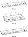
FIG. 1 is a schematic structural diagram of a modular assembled underframe according to the present invention; -
FIG. 2, FIG. 3 , andFIG. 4 are schematic diagrams of modular assembled underframe of different assembly lengths according to the present invention; -
FIG. 5 is a schematic structural diagram of a complete vehicle adopting a modular assembled underframe according to the present invention; -
FIG. 6 is a schematic structural diagram of a center beam module shown inFIG. 1 ; -
FIG. 7 is a schematic structural diagram of a first crossbeam module shown inFIG. 1 ; -
FIG. 8 is a schematic structural diagram of a sleeper beam module shown inFIG. 1 ; -
FIG. 9 is a schematic structural diagram of a second crossbeam module shown inFIG. 1 ; and -
FIG. 10 is a schematic structural diagram of interface assembling between modules. - In the
figures: 1 : Center beam module; 2: First crossbeam module; 3: Sleeper beam module; 4: Second crossbeam module; 5: Edge beam module; 6: Coupler buffer apparatus; 7: Bogie; - 101: Center beam; 102: Upper center pan; 103: Impact seat; 104: Module interface; 105: Module interface;
- 201: Support frame; 202: Container lock; 203: First crossbeam module interface; 204: Module interface;
- 401: Support frame; 402: Second crossbeam module interface; 403: Container lock.
- It should be pointed out that the following detailed descriptions are all illustrative and are intended to provide further descriptions of this application. Unless otherwise indicated, all technical terms and scientific terms used herein have the same meaning as commonly understood by those of ordinary skill in the art to which this application belongs.
- It should be noted that the terms used herein are merely for describing specific implementations, and are not intended to limit exemplary implementations according to this application. Unless clearly indicated in the context, singular forms used herein are also intended to include plural forms. In addition, it should be further understood that terms "including" and/or "comprising" used in this specification indicate that there are features, steps, operations, devices, assemblies, and/or combinations thereof.
- For ease of description, words "up", "down", "left", and "right" appearing in the present invention merely mean that they are consistent with the up, down, left, and right directions of the drawings themselves, and do not limit the structure. They are merely for the convenience of describing the present invention and simplifying the description, rather than indicating or implying that the device or the element referred to needs to have a specific orientation, be constructed and operated in a specific orientation, and therefore cannot be understood as a limitation on the present invention.
- Term explanation: terms such as "mounted", "connected", and "fixed", etc. in the present invention should be understood in a broad sense, for example, fixed connection, detachable connection, integral connection, mechanical connection, electrical connection, direct connection, indirect connection through an intermediation, internal connection between two elements, or an interaction relationship between two elements. In other words, specific meaning of the above terms in the present invention may be understood according to a specific situation.
- As described in the background, an underframe of an existing railway flatcar adopts a welded integral structure, and the underframe of the vehicle after completion of production of the underframe has a fixed size and cannot be disassembled and adjusted. For cargo containers of different sizes, when a vehicle with a fixed underframe is used for transportation, the underframe may be incapable of loading as a result of a relatively short transportation space, or a waste of transportation space may be caused as a result of an ample transportation space of the underframe, seriously affecting transportation efficiency and a transportation volume of railway transportation. For railway flatcars to be exported, because the underframe cannot be disassembled, long-distance sea transportation can be achieved through only complete-vehicle transportation, resulting in a large space occupied by the vehicle and high transportation costs. In order to resolve the above technical problems, this application discloses a railway modular assembled underframe and a whole vehicle structure. The underframe mainly includes a center beam module, a first crossbeam module, a sleeper beam module, a second crossbeam, and an edge beam module. The center beam module is at a middle position on the entire underframe, runs through the entire underframe, and is connected to a coupler buffer apparatus and a bogie. The coupler buffer apparatus and the bogie are mature technologies of railway freight wagon. The first crossbeam module is located at two ends of the underframe and is fixed to the center beam module through fasteners. The sleeper beam module is located at two ends of the center beam module, fixed to the center beam module through fasteners, and connected to the bogie. The second crossbeam module is located at the middle part of the underframe and is fixed to the center beam module. A number of second crossbeam modules is determined according to a length of the vehicle and a need of mounting a container. The edge beam module connects two adjacent modules through fasteners.
- In a typical implementation of this present application, as shown in
FIG. 1 , the modular assembled underframe provided in the embodiment of the present invention includes acenter beam module 1, afirst crossbeam module 2, a sleeper beam module 3, asecond crossbeam module 4, and anedge beam module 5;
Thecenter beam module 1 is at a middle position on the entire underframe, runs through the entire underframe along a longitudinal direction of the underframe, and is to be connected to a coupler buffer apparatus and a bogie. - There are at least two
first crossbeam modules 2 respectively located at two ends of the entire underframe, disposed along a transverse direction of the underframe, and fixed to thecenter beam module 1 through fasteners. - There are at least two sleeper beam modules 3 located near the ends of the entire underframe, disposed along the transverse direction of the underframe, and fixed to the center beam module through fasteners, and the sleeper beam module is connected to the bogie.
- There are at least two
edge beam modules 5 respectively located on two sides of the center beam module and configured to connect two adjacent modules through fasteners. - The
second crossbeam module 4 is located at the middle part of the underframe and is transversely fixed to the center beam module. A number of second crossbeam modules is determined according to a length of the vehicle and a need of mounting a container. - As shown in
FIG. 2 , a complete modular assembled underframe consists of at least onecenter beam module 1, twofirst crossbeam modules 2, and two sleeper beam modules 3, which form a rigid entirety after connection to support weights of the vehicle and to-be-transported cargo. - Further,
center beam modules 1 of different lengths may be selected based onFIG. 2 , andsecond crossbeam modules 4 of a specific number andedge beam modules 5 of a specific number are connected to adjust an overall length of the underframe. Specifically, as shown inFIG. 3 andFIG. 4 , inFIG. 3 , twoedge beam modules 5 and onesecond crossbeam module 4 are added, and onefirst crossbeam module 2 is also added between thesecond crossbeam module 4 and the sleeper beam module 3, and inFIG. 4 , twoedge beam modules 5 and threesecond crossbeam module 4 are added, and onefirst crossbeam module 2 is also added between thesecond crossbeam module 4 and the sleeper beam module 3. - As shown in
FIG. 6 , the abovecenter beam module 1 includes acenter beam 101, anupper center pan 102, animpact seat 103, amodule interface 104, and amodule interface 105. Thecenter beam 101 adopts a steel plate-welded box structure. Theupper center pan 102 is fixed at a lower part of thecenter beam 101 for connection to thebogie 4. Further, there are two upper center pans 102 symmetrically arranged at the bottom of thecenter beam 101 and near two ends of the center beam. Oneimpact seat 103 is fixed at each of the two ends of the two center beams 101. Theimpact seat 103 is to be connected to the coupler buffer apparatus 6. - The
upper center pan 102 and theimpact seat 103 are detachably mounted on thecenter beam 101. For specific structures of theupper center pan 102 and theimpact seat 103, refer to the prior art, and the specific structures are not an innovation point of this application. Therefore, details are not described herein again. Further, alternatively, theupper center pan 102 and theimpact seat 103 are directly welded on thecenter beam 101, which may be specifically selected according to an actual situation. - Moreover, the
module interface 104 and themodule interface 105 are generally directly welded on thecenter beam 101, and may be detachably connected to the center beam in a special case. Themodule interface 104 and themodule interface 105 are fixed on two sides of thecenter beam 101. Themodule interface 105 is configured to fix thesecond crossbeam module 4. Themodule interface 104 is configured to fix thefirst crossbeam module 2 and the sleeper beam module 3. - As shown in
FIG. 7 , thefirst crossbeam module 2 includes asupport frame 201, acontainer lock 202, and a firstcrossbeam module interface 203. Two ends of thesupport frame 201 are each provided with onecontainer lock 202. Thecontainer lock 202 is configured to fix a container. Thecontainer lock 202 is connected to the end of thesupport frame 201 through one pin. - The first
crossbeam module interface 203 matches themodule interface 104, and the two are connected through fasteners. The fasteners herein may be selected as existing bolt connection or may adopt other fastener connection, as long as a connection function is implemented. - The first
crossbeam module interface 203 is generally directly welded on thesupport frame 201, and may be detachably connected to thesupport frame 201 in a special case. - In addition, for a shape and a structure of the
support frame 201, refer to an existing structure. - As shown in
FIG. 8 , the sleeper beam module 3 is formed by a steel plate-welded box structure, or is formed in other forming manners, for example, is integrally formed, and is connected to thecenter beam module 1 through fasteners. For a shape and a structure of the sleeper beam module 3, refer to an existing structure. - Further, the fasteners herein may be selected as existing bolt connection or may adopt other fastener connection, as long as a connection function is implemented.
- As shown in
FIG. 9 , thesecond crossbeam module 4 includes asupport frame 401, acontainer lock 403, and a secondcrossbeam module interface 402. The top of thesupport frame 401 is provided with twocontainer locks 403, and the container locks 403 are located near two ends of the support frame. Thecontainer lock 402 is connected to the end of thesupport frame 401 through one pin. For details, refer to the drawings. - The second
crossbeam module interface 402 matches themodule interface 105 of thecenter beam module 1, and the two are connected through fasteners to connect the second crossbeam module and the center beam module. The secondcrossbeam module interface 402 is generally directly welded on thesupport frame 401, and may be detachably connected to thesupport frame 401 in a special case. - Further, the fasteners herein may be selected as existing bolt connection or may adopt other fastener connection, as long as a connection function is implemented.
- As shown in
FIG. 10 , thecenter beam module 1 and thesecond crossbeam module 4, and thesecond crossbeam module 4 and theedge beam module 5 are all connected through fasteners to ensure that the modules can be repeatedly assembled. A module interface structure between thecenter beam module 1 and thefirst crossbeam module 2 is similar to a module interface structure between thecenter beam module 1 and the sleeper beam module 3, and details are not described herein again. - Further, in this embodiment, the coupler buffer apparatus and the bogie are existing mature railway wagon technologies, and therefore are not described in detail in this embodiment again.
- This embodiment provides a complete-vehicle structure including the railway modular assembled underframe in
Embodiment 1. Specifically, as shown inFIG. 5 , the complete-vehicle structure includes acenter beam module 1, fourfirst crossbeam modules 2, two sleeper beam modules 3, onesecond crossbeam module 4, twobogies 7, and two coupler buffer apparatuses 6. Thesecond crossbeam module 4 is mounted at the middle part of thecenter beam module 1. The twofirst crossbeam modules 2 are disposed on two ends of thecenter beam module 1, the two sleeper beam modules 3 are disposed near the end of thecenter beam module 1, and onefirst crossbeam module 2 is provided between each of the sleeper beam modules 3 and thesecond crossbeam module 4. Thefirst crossbeam module 2, the sleeper beam module 3, and thesecond crossbeam module 4 are connected to thecenter beam module 1 through each module interface. - One coupler buffer apparatus 6 is respectively mounted on each of the two ends of the
center beam module 1, and a lower part of thecenter beam module 1 and the sleeper beam module 3 are both connected to thebogie 7. - It should be noted herein that the coupler buffer apparatus 6 and the
bogie 7 are existing mature railway wagon technologies, and therefore are not described in this patent. - Finally, it should be noted that the above embodiments are merely for describing and not intended to limit the technical solutions of the present invention. Although the present invention has been described in detail with reference to the above embodiments, those of ordinary skill in the art should understand that they can still make modifications to the technical solutions recited in the above embodiments or make equivalent replacements to a part or all of the technical features thereof; and the modifications or replacements do not cause essence of the corresponding technical solutions to depart from the scope of the technical solutions of the embodiments of the present invention.
- The above descriptions are merely exemplary embodiments of this application and are not intended to limit this application. For those skilled in the art, this application may have various modifications and changes. Any modification, equivalent replacement, and improvement made without departing from the scope and the principle of this application shall fall within the protection scope of this application.
Claims (10)
- A flatcar underframe for railway freight, comprising: a center beam module, a first crossbeam module, a sleeper beam module, and an edge beam module, wherein
the center beam module is at a middle position on the entire underframe, runs through the entire underframe along a longitudinal direction of the underframe, and is to be connected to a coupler buffer apparatus and a bogie;
there are at least two first crossbeam modules respectively located at two ends of the entire underframe, disposed along a transverse direction of the underframe, and fixed to the center beam module through fasteners;
there are at least two sleeper beam modules located near the two ends of the underframe, disposed along the transverse direction of the underframe, and fixed to the center beam module through fasteners, wherein the sleeper beam module is to be connected to the bogie; and
there are at least two edge beam modules respectively located on two sides of the center beam module and configured to connect two adjacent modules through fasteners. - The flatcar underframe for railway freight according to claim 1, wherein a first crossbeam module is further provided at a middle part of the underframe and is located between the two sleeper beam modules.
- The flatcar underframe for railway freight according to claim 1, further comprising a second crossbeam module located at a middle part of the underframe and fixed to the center beam module.
- The flatcar underframe for railway freight according to claim 3, wherein a number of second crossbeam modules is determined according to a length of the vehicle and a need of mounting a container.
- The flatcar underframe for railway freight according to claim 1, wherein the center beam module comprises an impact seat, a center beam, and an upper center pan; and the center beam is provided with a sleeper beam module interface and a first crossbeam module interface, and a length of the center beam is adjustable as required, wherein the upper center pan is located at a lower part of the center beam and is to be connected to the bogie; and the impact seat is located at two ends of the center beam and is to be connected to the coupler buffer apparatus.
- The flatcar underframe for railway freight according to claim 5, wherein a second crossbeam module interface is further provided on the center beam.
- The flatcar underframe for railway freight according to claim 1, wherein a container lock is disposed on the top of the first crossbeam module, the container lock being located near an end of the crossbeam module, and a standard interface is disposed at a middle part of the first crossbeam module for connection to the center beam module.
- The flatcar underframe for railway freight according to claim 1, wherein the sleeper beam module is assembled and welded into a box-shaped structure by using plates, and a standard interface is disposed at a middle part of the sleeper beam module for connection to the center beam module.
- The flatcar underframe for railway freight according to claim 1, wherein a container lock is disposed on the top of the second crossbeam module, the container lock being located near an end of the crossbeam module, and a standard interface is disposed at a middle part of the second crossbeam module for connection to the center beam module.
- A complete-vehicle structure, comprising: the above flatcar underframe for railway freight, bogie, and coupler buffer apparatus, wherein the coupler buffer apparatus is mounted on two ends of the underframe, and the bogie is disposed at a lower part of the underframe and connected to the underframe.
Applications Claiming Priority (2)
| Application Number | Priority Date | Filing Date | Title |
|---|---|---|---|
| CN201910302558.8A CN110065516B (en) | 2019-04-16 | 2019-04-16 | A railway modular assembled chassis and a vehicle structure including the chassis |
| PCT/CN2019/087155 WO2020211136A1 (en) | 2019-04-16 | 2019-05-16 | Railway modular assembling underframe and full vehicle structure comprising same |
Publications (3)
| Publication Number | Publication Date |
|---|---|
| EP3800105A1 true EP3800105A1 (en) | 2021-04-07 |
| EP3800105A4 EP3800105A4 (en) | 2021-10-13 |
| EP3800105B1 EP3800105B1 (en) | 2024-12-11 |
Family
ID=67367810
Family Applications (1)
| Application Number | Title | Priority Date | Filing Date |
|---|---|---|---|
| EP19925427.7A Active EP3800105B1 (en) | 2019-04-16 | 2019-05-16 | Railway modular assembling underframe and full vehicle structure comprising same |
Country Status (3)
| Country | Link |
|---|---|
| EP (1) | EP3800105B1 (en) |
| CN (1) | CN110065516B (en) |
| WO (1) | WO2020211136A1 (en) |
Cited By (4)
| Publication number | Priority date | Publication date | Assignee | Title |
|---|---|---|---|---|
| RU2795461C1 (en) * | 2022-12-12 | 2023-05-03 | Акционерное общество "Научно-производственная корпорация "Уралвагонзавод" имени Ф.Э. Дзержинского" | Railway flatcar |
| EP4316940A1 (en) | 2022-08-05 | 2024-02-07 | Cgl | Wagon structure for transporting containers |
| FR3138640A1 (en) * | 2022-08-05 | 2024-02-09 | Cgl | WAGON STRUCTURE FOR CONTAINER TRANSPORT |
| EP4344974A1 (en) * | 2022-09-27 | 2024-04-03 | Siemens Mobility GmbH | Stiffening element |
Families Citing this family (13)
| Publication number | Priority date | Publication date | Assignee | Title |
|---|---|---|---|---|
| CN111559402B (en) * | 2020-05-25 | 2021-08-10 | 中车山东机车车辆有限公司 | Full-riveting modular center sill structure, flatcar underframe and railway flatcar |
| DE102020119526A1 (en) * | 2020-07-23 | 2022-01-27 | Deutsche Bahn Aktiengesellschaft | UNDERFRAME OF A RAIL VEHICLE |
| DE102020134258A1 (en) * | 2020-12-18 | 2022-06-23 | Deutsche Bahn Aktiengesellschaft | UNDERFRAME OF A RAIL VEHICLE |
| CN115123330A (en) * | 2021-03-24 | 2022-09-30 | 中车山东机车车辆有限公司 | Vehicle body chassis and vehicle |
| CN114394126B (en) * | 2021-11-25 | 2025-04-11 | 中国铁建高新装备股份有限公司 | Frame of a rail flaw detection vehicle |
| CN114619164B (en) * | 2022-03-18 | 2023-08-29 | 中车太原机车车辆有限公司 | Adjustment-free manufacturing method for container flatcar body |
| CN116279628A (en) * | 2023-04-26 | 2023-06-23 | 中车齐齐哈尔车辆有限公司 | Modularized container flatcar underframe capable of being repeatedly connected |
| CN116552588B (en) * | 2023-06-19 | 2025-11-28 | 中车齐齐哈尔车辆有限公司 | Railway flatcar and car body of railway flatcar |
| CN116654031A (en) * | 2023-06-19 | 2023-08-29 | 中车齐齐哈尔车辆有限公司 | A car body of a railway flat car and a longitudinal beam of a railway flat car |
| CN117341752B (en) * | 2023-10-17 | 2026-01-27 | 中国铁建高新装备股份有限公司 | Split type chassis of two-stage balanced structure for transporting long and large cargoes |
| CN117341753A (en) * | 2023-10-31 | 2024-01-05 | 中车青岛四方机车车辆股份有限公司 | End chassis, car chassis and rail vehicles |
| CN117565904B (en) * | 2023-12-11 | 2026-02-06 | 中车齐齐哈尔车辆有限公司 | Railway special flat car powered by locomotive electric power |
| CN119283924B (en) * | 2024-10-14 | 2026-05-05 | 中车唐山机车车辆有限公司 | Underframe, middle beam underframe and rail vehicle |
Family Cites Families (14)
| Publication number | Priority date | Publication date | Assignee | Title |
|---|---|---|---|---|
| US740187A (en) * | 1900-11-15 | 1903-09-29 | George W Scott | System of underframing for railway-cars. |
| US1140672A (en) * | 1912-11-08 | 1915-05-25 | American Car & Foundry Co | Underframe. |
| US2788750A (en) * | 1954-01-13 | 1957-04-16 | United States Steel Corp | Railway car underframe construction |
| US3003436A (en) * | 1959-12-03 | 1961-10-10 | Pullman Inc | Method and apparatus for protecting vehicle loads |
| CN101837791B (en) * | 2010-04-14 | 2012-03-28 | 南车眉山车辆有限公司 | Multipurpose broad-gauge container platform wagon |
| CN103170754A (en) * | 2013-04-03 | 2013-06-26 | 齐齐哈尔鑫拓金属铆焊有限责任公司 | Railway box van dragging beam assembling welding process |
| CN103465921B (en) * | 2013-09-10 | 2016-02-10 | 南车二七车辆有限公司 | A kind of special vehicle car body of rapid container transportation |
| CN204548139U (en) * | 2015-04-22 | 2015-08-12 | 宝鸡南车时代工程机械有限公司 | For the vehicle frame of rail of subway grinding machine |
| CN108170876A (en) * | 2016-12-07 | 2018-06-15 | 中车齐齐哈尔车辆有限公司 | The design method and system of railway container vehicle |
| CN108162996B (en) * | 2016-12-07 | 2019-08-06 | 中车齐齐哈尔车辆有限公司 | The car body design method and apparatus of railway freight-car |
| CN106740908A (en) * | 2016-12-20 | 2017-05-31 | 中车山东机车车辆有限公司 | A kind of low loading end Multi-purpose railway flatcar |
| CN208411729U (en) * | 2018-07-11 | 2019-01-22 | 中铁磁浮科技(成都)有限公司 | A kind of magnetic floating vehicle body structure |
| CN109383552B (en) * | 2018-09-06 | 2020-04-14 | 中车青岛四方机车车辆股份有限公司 | a rail vehicle |
| CN109229121B (en) * | 2018-11-16 | 2024-06-25 | 中车齐齐哈尔车辆有限公司 | Flatcar body for railway container |
-
2019
- 2019-04-16 CN CN201910302558.8A patent/CN110065516B/en active Active
- 2019-05-16 WO PCT/CN2019/087155 patent/WO2020211136A1/en not_active Ceased
- 2019-05-16 EP EP19925427.7A patent/EP3800105B1/en active Active
Cited By (5)
| Publication number | Priority date | Publication date | Assignee | Title |
|---|---|---|---|---|
| EP4316940A1 (en) | 2022-08-05 | 2024-02-07 | Cgl | Wagon structure for transporting containers |
| FR3138640A1 (en) * | 2022-08-05 | 2024-02-09 | Cgl | WAGON STRUCTURE FOR CONTAINER TRANSPORT |
| FR3138641A1 (en) | 2022-08-05 | 2024-02-09 | Cgl | WAGON STRUCTURE FOR TRANSPORTING CONTAINERS S |
| EP4344974A1 (en) * | 2022-09-27 | 2024-04-03 | Siemens Mobility GmbH | Stiffening element |
| RU2795461C1 (en) * | 2022-12-12 | 2023-05-03 | Акционерное общество "Научно-производственная корпорация "Уралвагонзавод" имени Ф.Э. Дзержинского" | Railway flatcar |
Also Published As
| Publication number | Publication date |
|---|---|
| EP3800105B1 (en) | 2024-12-11 |
| EP3800105A4 (en) | 2021-10-13 |
| CN110065516B (en) | 2020-09-29 |
| WO2020211136A1 (en) | 2020-10-22 |
| CN110065516A (en) | 2019-07-30 |
Similar Documents
| Publication | Publication Date | Title |
|---|---|---|
| EP3800105B1 (en) | Railway modular assembling underframe and full vehicle structure comprising same | |
| CN107600097B (en) | A lightweight railway hopper truck chassis and method | |
| CN109229121B (en) | Flatcar body for railway container | |
| EP3919340B1 (en) | Frame and freight train | |
| CA2688382A1 (en) | Railroad well car with open truss sides | |
| RU2345918C1 (en) | Gondola wagon of aluminium alloys | |
| CN111252101A (en) | Railway carries on back multi-functional transport vechicle chassis and transport vechicle | |
| US2764299A (en) | Cushioned undererame | |
| CN111762216B (en) | Railway container flat car body | |
| RU191948U1 (en) | Wagon-Hopper | |
| WO2021114346A1 (en) | Rail vehicle, and vehicle body and end underframe thereof | |
| CN116513248A (en) | Railway vehicle carriage and railway vehicle | |
| RU2329906C2 (en) | Car-platform | |
| EP4008600B1 (en) | Primary suspension device, bogie and railway vehicle | |
| CN201506396U (en) | Self-unloading wagon carriage and self-unloading wagon with the same | |
| EP3875341B1 (en) | Freight train chassis and freight train | |
| KR20250134130A (en) | Body of a flat car and longitudinal beam of a flat car | |
| CN219928347U (en) | Fixed wing unmanned aerial vehicle fixing device and storage and transportation device | |
| CN202784410U (en) | Light exchange tank type container | |
| RU182496U1 (en) | FOUR-AXLE HOPPER WAGON | |
| CA2894724A1 (en) | Intermodal shipping container box | |
| CN218750408U (en) | Quick change assembly and electric vehicle | |
| CN108639090A (en) | A kind of rail traffic vehicles and its modularization bogie | |
| RU61232U1 (en) | WAGON PLATFORM | |
| US3339501A (en) | Railroad car supporting structure |
Legal Events
| Date | Code | Title | Description |
|---|---|---|---|
| STAA | Information on the status of an ep patent application or granted ep patent |
Free format text: STATUS: THE INTERNATIONAL PUBLICATION HAS BEEN MADE |
|
| PUAI | Public reference made under article 153(3) epc to a published international application that has entered the european phase |
Free format text: ORIGINAL CODE: 0009012 |
|
| STAA | Information on the status of an ep patent application or granted ep patent |
Free format text: STATUS: REQUEST FOR EXAMINATION WAS MADE |
|
| 17P | Request for examination filed |
Effective date: 20201230 |
|
| AK | Designated contracting states |
Kind code of ref document: A1 Designated state(s): AL AT BE BG CH CY CZ DE DK EE ES FI FR GB GR HR HU IE IS IT LI LT LU LV MC MK MT NL NO PL PT RO RS SE SI SK SM TR |
|
| AX | Request for extension of the european patent |
Extension state: BA ME |
|
| A4 | Supplementary search report drawn up and despatched |
Effective date: 20210913 |
|
| RIC1 | Information provided on ipc code assigned before grant |
Ipc: B61D 3/16 20060101ALI20210907BHEP Ipc: B61F 1/10 20060101ALI20210907BHEP Ipc: B61F 1/12 20060101ALI20210907BHEP Ipc: B61D 3/20 20060101ALI20210907BHEP Ipc: B61F 1/02 20060101AFI20210907BHEP |
|
| DAV | Request for validation of the european patent (deleted) | ||
| DAX | Request for extension of the european patent (deleted) | ||
| GRAP | Despatch of communication of intention to grant a patent |
Free format text: ORIGINAL CODE: EPIDOSNIGR1 |
|
| STAA | Information on the status of an ep patent application or granted ep patent |
Free format text: STATUS: GRANT OF PATENT IS INTENDED |
|
| RIC1 | Information provided on ipc code assigned before grant |
Ipc: B61D 3/16 20060101ALI20240621BHEP Ipc: B61F 1/10 20060101ALI20240621BHEP Ipc: B61F 1/12 20060101ALI20240621BHEP Ipc: B61D 3/20 20060101ALI20240621BHEP Ipc: B61F 1/02 20060101AFI20240621BHEP |
|
| INTG | Intention to grant announced |
Effective date: 20240710 |
|
| GRAS | Grant fee paid |
Free format text: ORIGINAL CODE: EPIDOSNIGR3 |
|
| GRAA | (expected) grant |
Free format text: ORIGINAL CODE: 0009210 |
|
| STAA | Information on the status of an ep patent application or granted ep patent |
Free format text: STATUS: THE PATENT HAS BEEN GRANTED |
|
| AK | Designated contracting states |
Kind code of ref document: B1 Designated state(s): AL AT BE BG CH CY CZ DE DK EE ES FI FR GB GR HR HU IE IS IT LI LT LU LV MC MK MT NL NO PL PT RO RS SE SI SK SM TR |
|
| REG | Reference to a national code |
Ref country code: GB Ref legal event code: FG4D |
|
| REG | Reference to a national code |
Ref country code: CH Ref legal event code: EP |
|
| REG | Reference to a national code |
Ref country code: IE Ref legal event code: FG4D |
|
| REG | Reference to a national code |
Ref country code: DE Ref legal event code: R096 Ref document number: 602019063518 Country of ref document: DE |
|
| REG | Reference to a national code |
Ref country code: LT Ref legal event code: MG9D |
|
| PG25 | Lapsed in a contracting state [announced via postgrant information from national office to epo] |
Ref country code: HR Free format text: LAPSE BECAUSE OF FAILURE TO SUBMIT A TRANSLATION OF THE DESCRIPTION OR TO PAY THE FEE WITHIN THE PRESCRIBED TIME-LIMIT Effective date: 20241211 |
|
| PG25 | Lapsed in a contracting state [announced via postgrant information from national office to epo] |
Ref country code: FI Free format text: LAPSE BECAUSE OF FAILURE TO SUBMIT A TRANSLATION OF THE DESCRIPTION OR TO PAY THE FEE WITHIN THE PRESCRIBED TIME-LIMIT Effective date: 20241211 |
|
| PG25 | Lapsed in a contracting state [announced via postgrant information from national office to epo] |
Ref country code: BG Free format text: LAPSE BECAUSE OF FAILURE TO SUBMIT A TRANSLATION OF THE DESCRIPTION OR TO PAY THE FEE WITHIN THE PRESCRIBED TIME-LIMIT Effective date: 20241211 |
|
| REG | Reference to a national code |
Ref country code: NL Ref legal event code: MP Effective date: 20241211 |
|
| PG25 | Lapsed in a contracting state [announced via postgrant information from national office to epo] |
Ref country code: ES Free format text: LAPSE BECAUSE OF FAILURE TO SUBMIT A TRANSLATION OF THE DESCRIPTION OR TO PAY THE FEE WITHIN THE PRESCRIBED TIME-LIMIT Effective date: 20241211 |
|
| PG25 | Lapsed in a contracting state [announced via postgrant information from national office to epo] |
Ref country code: NO Free format text: LAPSE BECAUSE OF FAILURE TO SUBMIT A TRANSLATION OF THE DESCRIPTION OR TO PAY THE FEE WITHIN THE PRESCRIBED TIME-LIMIT Effective date: 20250311 |
|
| PG25 | Lapsed in a contracting state [announced via postgrant information from national office to epo] |
Ref country code: GR Free format text: LAPSE BECAUSE OF FAILURE TO SUBMIT A TRANSLATION OF THE DESCRIPTION OR TO PAY THE FEE WITHIN THE PRESCRIBED TIME-LIMIT Effective date: 20250312 Ref country code: LV Free format text: LAPSE BECAUSE OF FAILURE TO SUBMIT A TRANSLATION OF THE DESCRIPTION OR TO PAY THE FEE WITHIN THE PRESCRIBED TIME-LIMIT Effective date: 20241211 |
|
| PG25 | Lapsed in a contracting state [announced via postgrant information from national office to epo] |
Ref country code: RS Free format text: LAPSE BECAUSE OF FAILURE TO SUBMIT A TRANSLATION OF THE DESCRIPTION OR TO PAY THE FEE WITHIN THE PRESCRIBED TIME-LIMIT Effective date: 20250311 |
|
| PG25 | Lapsed in a contracting state [announced via postgrant information from national office to epo] |
Ref country code: NL Free format text: LAPSE BECAUSE OF FAILURE TO SUBMIT A TRANSLATION OF THE DESCRIPTION OR TO PAY THE FEE WITHIN THE PRESCRIBED TIME-LIMIT Effective date: 20241211 |
|
| REG | Reference to a national code |
Ref country code: AT Ref legal event code: MK05 Ref document number: 1750192 Country of ref document: AT Kind code of ref document: T Effective date: 20241211 |
|
| PG25 | Lapsed in a contracting state [announced via postgrant information from national office to epo] |
Ref country code: SM Free format text: LAPSE BECAUSE OF FAILURE TO SUBMIT A TRANSLATION OF THE DESCRIPTION OR TO PAY THE FEE WITHIN THE PRESCRIBED TIME-LIMIT Effective date: 20241211 |
|
| PG25 | Lapsed in a contracting state [announced via postgrant information from national office to epo] |
Ref country code: PL Free format text: LAPSE BECAUSE OF FAILURE TO SUBMIT A TRANSLATION OF THE DESCRIPTION OR TO PAY THE FEE WITHIN THE PRESCRIBED TIME-LIMIT Effective date: 20241211 |
|
| PGFP | Annual fee paid to national office [announced via postgrant information from national office to epo] |
Ref country code: DE Payment date: 20250623 Year of fee payment: 7 |
|
| PG25 | Lapsed in a contracting state [announced via postgrant information from national office to epo] |
Ref country code: IS Free format text: LAPSE BECAUSE OF FAILURE TO SUBMIT A TRANSLATION OF THE DESCRIPTION OR TO PAY THE FEE WITHIN THE PRESCRIBED TIME-LIMIT Effective date: 20250411 |
|
| PG25 | Lapsed in a contracting state [announced via postgrant information from national office to epo] |
Ref country code: PT Free format text: LAPSE BECAUSE OF FAILURE TO SUBMIT A TRANSLATION OF THE DESCRIPTION OR TO PAY THE FEE WITHIN THE PRESCRIBED TIME-LIMIT Effective date: 20250411 |
|
| PG25 | Lapsed in a contracting state [announced via postgrant information from national office to epo] |
Ref country code: EE Free format text: LAPSE BECAUSE OF FAILURE TO SUBMIT A TRANSLATION OF THE DESCRIPTION OR TO PAY THE FEE WITHIN THE PRESCRIBED TIME-LIMIT Effective date: 20241211 |
|
| PGFP | Annual fee paid to national office [announced via postgrant information from national office to epo] |
Ref country code: FR Payment date: 20250523 Year of fee payment: 7 |
|
| PGFP | Annual fee paid to national office [announced via postgrant information from national office to epo] |
Ref country code: CH Payment date: 20250626 Year of fee payment: 7 |
|
| PG25 | Lapsed in a contracting state [announced via postgrant information from national office to epo] |
Ref country code: RO Free format text: LAPSE BECAUSE OF FAILURE TO SUBMIT A TRANSLATION OF THE DESCRIPTION OR TO PAY THE FEE WITHIN THE PRESCRIBED TIME-LIMIT Effective date: 20241211 Ref country code: AT Free format text: LAPSE BECAUSE OF FAILURE TO SUBMIT A TRANSLATION OF THE DESCRIPTION OR TO PAY THE FEE WITHIN THE PRESCRIBED TIME-LIMIT Effective date: 20241211 |
|
| PG25 | Lapsed in a contracting state [announced via postgrant information from national office to epo] |
Ref country code: SK Free format text: LAPSE BECAUSE OF FAILURE TO SUBMIT A TRANSLATION OF THE DESCRIPTION OR TO PAY THE FEE WITHIN THE PRESCRIBED TIME-LIMIT Effective date: 20241211 |
|
| PG25 | Lapsed in a contracting state [announced via postgrant information from national office to epo] |
Ref country code: CZ Free format text: LAPSE BECAUSE OF FAILURE TO SUBMIT A TRANSLATION OF THE DESCRIPTION OR TO PAY THE FEE WITHIN THE PRESCRIBED TIME-LIMIT Effective date: 20241211 |
|
| PG25 | Lapsed in a contracting state [announced via postgrant information from national office to epo] |
Ref country code: IT Free format text: LAPSE BECAUSE OF FAILURE TO SUBMIT A TRANSLATION OF THE DESCRIPTION OR TO PAY THE FEE WITHIN THE PRESCRIBED TIME-LIMIT Effective date: 20241211 |
|
| PG25 | Lapsed in a contracting state [announced via postgrant information from national office to epo] |
Ref country code: SE Free format text: LAPSE BECAUSE OF FAILURE TO SUBMIT A TRANSLATION OF THE DESCRIPTION OR TO PAY THE FEE WITHIN THE PRESCRIBED TIME-LIMIT Effective date: 20241211 |
|
| REG | Reference to a national code |
Ref country code: DE Ref legal event code: R097 Ref document number: 602019063518 Country of ref document: DE |
|
| PG25 | Lapsed in a contracting state [announced via postgrant information from national office to epo] |
Ref country code: DK Free format text: LAPSE BECAUSE OF FAILURE TO SUBMIT A TRANSLATION OF THE DESCRIPTION OR TO PAY THE FEE WITHIN THE PRESCRIBED TIME-LIMIT Effective date: 20241211 |
|
| PLBE | No opposition filed within time limit |
Free format text: ORIGINAL CODE: 0009261 |
|
| STAA | Information on the status of an ep patent application or granted ep patent |
Free format text: STATUS: NO OPPOSITION FILED WITHIN TIME LIMIT |
|
| 26N | No opposition filed |
Effective date: 20250912 |
|
| PG25 | Lapsed in a contracting state [announced via postgrant information from national office to epo] |
Ref country code: LU Free format text: LAPSE BECAUSE OF NON-PAYMENT OF DUE FEES Effective date: 20250516 |
|
| GBPC | Gb: european patent ceased through non-payment of renewal fee |
Effective date: 20250516 |
|
| REG | Reference to a national code |
Ref country code: BE Ref legal event code: MM Effective date: 20250531 |
|
| PG25 | Lapsed in a contracting state [announced via postgrant information from national office to epo] |
Ref country code: MC Free format text: LAPSE BECAUSE OF FAILURE TO SUBMIT A TRANSLATION OF THE DESCRIPTION OR TO PAY THE FEE WITHIN THE PRESCRIBED TIME-LIMIT Effective date: 20241211 |
|
| PG25 | Lapsed in a contracting state [announced via postgrant information from national office to epo] |
Ref country code: GB Free format text: LAPSE BECAUSE OF NON-PAYMENT OF DUE FEES Effective date: 20250516 |
|
| PG25 | Lapsed in a contracting state [announced via postgrant information from national office to epo] |
Ref country code: IE Free format text: LAPSE BECAUSE OF NON-PAYMENT OF DUE FEES Effective date: 20250516 |
|
| PG25 | Lapsed in a contracting state [announced via postgrant information from national office to epo] |
Ref country code: BE Free format text: LAPSE BECAUSE OF NON-PAYMENT OF DUE FEES Effective date: 20250531 |