EP3802994B1 - Selbstverriegelnder teleskopmast - Google Patents
Selbstverriegelnder teleskopmast Download PDFInfo
- Publication number
- EP3802994B1 EP3802994B1 EP19732819.8A EP19732819A EP3802994B1 EP 3802994 B1 EP3802994 B1 EP 3802994B1 EP 19732819 A EP19732819 A EP 19732819A EP 3802994 B1 EP3802994 B1 EP 3802994B1
- Authority
- EP
- European Patent Office
- Prior art keywords
- tube
- auto
- lock
- latch
- base
- Prior art date
- Legal status (The legal status is an assumption and is not a legal conclusion. Google has not performed a legal analysis and makes no representation as to the accuracy of the status listed.)
- Active
Links
Images


Classifications
-
- B—PERFORMING OPERATIONS; TRANSPORTING
- B66—HOISTING; LIFTING; HAULING
- B66C—CRANES; LOAD-ENGAGING ELEMENTS OR DEVICES FOR CRANES, CAPSTANS, WINCHES, OR TACKLES
- B66C23/00—Cranes comprising essentially a beam, boom, or triangular structure acting as a cantilever and mounted for translatory of swinging movements in vertical or horizontal planes or a combination of such movements, e.g. jib-cranes, derricks, tower cranes
- B66C23/62—Constructional features or details
- B66C23/64—Jibs
- B66C23/70—Jibs constructed of sections adapted to be assembled to form jibs or various lengths
- B66C23/701—Jibs constructed of sections adapted to be assembled to form jibs or various lengths telescopic
- B66C23/708—Jibs constructed of sections adapted to be assembled to form jibs or various lengths telescopic locking devices for telescopic jibs
-
- E—FIXED CONSTRUCTIONS
- E04—BUILDING
- E04H—BUILDINGS OR LIKE STRUCTURES FOR PARTICULAR PURPOSES; SWIMMING OR SPLASH BATHS OR POOLS; MASTS; FENCING; TENTS OR CANOPIES, IN GENERAL
- E04H12/00—Towers; Masts or poles; Chimney stacks; Water-towers; Methods of erecting such structures
- E04H12/18—Towers; Masts or poles; Chimney stacks; Water-towers; Methods of erecting such structures movable or with movable sections, e.g. rotatable or telescopic
- E04H12/182—Towers; Masts or poles; Chimney stacks; Water-towers; Methods of erecting such structures movable or with movable sections, e.g. rotatable or telescopic telescopic
-
- F—MECHANICAL ENGINEERING; LIGHTING; HEATING; WEAPONS; BLASTING
- F16—ENGINEERING ELEMENTS AND UNITS; GENERAL MEASURES FOR PRODUCING AND MAINTAINING EFFECTIVE FUNCTIONING OF MACHINES OR INSTALLATIONS; THERMAL INSULATION IN GENERAL
- F16B—DEVICES FOR FASTENING OR SECURING CONSTRUCTIONAL ELEMENTS OR MACHINE PARTS TOGETHER, e.g. NAILS, BOLTS, CIRCLIPS, CLAMPS, CLIPS OR WEDGES; JOINTS OR JOINTING
- F16B7/00—Connections of rods or tubes, e.g. of non-circular section, mutually, including resilient connections
- F16B7/10—Telescoping systems
- F16B7/105—Telescoping systems locking in discrete positions, e.g. in extreme extended position
-
- F—MECHANICAL ENGINEERING; LIGHTING; HEATING; WEAPONS; BLASTING
- F16—ENGINEERING ELEMENTS AND UNITS; GENERAL MEASURES FOR PRODUCING AND MAINTAINING EFFECTIVE FUNCTIONING OF MACHINES OR INSTALLATIONS; THERMAL INSULATION IN GENERAL
- F16B—DEVICES FOR FASTENING OR SECURING CONSTRUCTIONAL ELEMENTS OR MACHINE PARTS TOGETHER, e.g. NAILS, BOLTS, CIRCLIPS, CLAMPS, CLIPS OR WEDGES; JOINTS OR JOINTING
- F16B2200/00—Constructional details of connections not covered for in other groups of this subclass
- F16B2200/91—Use of a pneumatic action
Definitions
- the present invention relates to a telescoping mast assembly according to claim 1. It finds particular application in conjunction with auto-locking/unlocking telescoping masts and will be described with particular reference thereto. However, it is to be appreciated that the present exemplary embodiment is also amenable to other like applications.
- Pneumatically actuated telescoping masts are known in the art, and are, for example, mounted on the roof of a motor vehicle such as an emergency vehicle or utility vehicle. Alternatively, mounting configurations may also involve the floor of a vehicle, allowing the telescoping mast to extend through the roof of the vehicle.
- the mast is generally used for positioning various devices at an elevated point above the vehicle.
- Pneumatically actuated telescoping masts are particularly advantageous for such uses, because they are lightweight, compact in the retracted position, and quickly transportable to a site by the vehicles on which they are mounted.
- Pneumatically actuated telescoping masts are extended and retracted using air under pressure and, in a fully extended use position, are usually vertical, although they can be inclined in the use position.
- the vehicle on which the telescoping mast is mounted typically includes a compressor and appropriate pneumatic controls for displacing the mast sections between retracted and extended positions.
- each telescoping section includes a hollow cylindrical body with a collar secured to an end thereof.
- the collar can include a keyway (or key) for rotationally interlocking the telescoping section with an adjacent telescoping section or sections.
- the collar can also provide reinforcement to the cylindrical body.
- JP S62 180148 U discloses a lock for securing telescoping tube sections wherin the lock relies on rotating motion of the lock to lock and unlock.
- US 3 688 455 A sicloses lock mechanisms that employ rotary spiders that rely on rotating motion for locking and unlocking.
- US 2 708 493 discloses a linearly movable lock pin in a telescoping mast assembly.
- US 9 670 948 discloses a locking mechanism that requires the motive force of a mast power screw to cause the unlocking sequence when the mast nests, wherein the lock uses a rotating motion to lock and unlock.
- an auto-lock assembly for a telescoping mast having a plurality of telescoping tube sections configurable between a retracted position and an extended position.
- the assembly includes a first latch pin mounted perpendicularly to a first tube section, the first latch pin being pre-loaded toward a locked position with a second tube section and configured to move linearly to an unlocked position with respect to the second tube section.
- a first latch lever is mounted to the first latch pin, the first latch lever configured to pivot between a parallel position and a rotated position with respect to the first tube section.
- a guide plate is mounted parallel to a third tube section and an angled bearing surface disposed on an upper portion of the guide plate, the guide plate and angled bearing surface configured to contact the first latch lever.
- the first latch pin is pre-loaded to move linearly into the locked position with the second tube section when the second tube section is in the extended position with respect to the first tube section. Further, the first latch pin moves linearly from the locked position to the unlocked position by the pivoting movement of the first latch lever and the first latch lever pivots from the parallel position to the rotated position by the contact with the angled bearing surface of the guide plate when the first tube section is in the retracted position with respect to the third tube section to thereby allow the retracted position of the second tube section with respect to the first tube section.
- a telescoping mast in accordance with another aspect of the exemplary embodiment, includes a plurality of telescoping mast sections including a base tube, an intermediate tube, and an end tube, the intermediate and end tube adapted to be telescopically received in the base tube, a base auto-lock having a collar for mounting to the base tube, and an intermediate auto-lock having a collar for mounting to the intermediate tube.
- Both the base auto-lock and the intermediate auto-lock include a latch pin housed in the collar and configured to move linearly between a locked and unlocked position, a latch lever mounted to the latch pin and configured to pivot between a parallel position and a rotated position with respect to the plurality of telescoping mast sections, and a guide plate mounted on the collar and oriented parallel to the plurality of telescoping mast sections.
- the base auto-lock latch pin is movable into the locked position with the intermediate tube when the intermediate tube is fully extended out of the base tube.
- the intermediate auto-lock latch pin is movable into the locked position with the end tube when the end tube is fully extended out of the intermediate tube and is movable into the unlocked position with the end tube when the intermediate auto-lock latch lever pivots from the parallel position to the rotated position by contact with the base auto-lock guide plate when the intermediate tube is retracted into the base tube, thereby allowing the end tube to retract into the intermediate tube.
- an auto-lock for use with a telescoping mast having a plurality of tube sections.
- the auto-lock includes a plurality of collars, each collar mountable to an associated tube section, a plurality of spring-activated latch pins, each latch pin housed in an associated collar and oriented perpendicular to the plurality of tube sections, and configured to move linearly between a locked and an unlocked position with an associated tube section, a plurality of latch levers, each lever mounted on an associated latch pin and configured to pivot between a parallel position and a rotated position with respect to the plurality of tube sections and to move the associated latch pin into the unlocked position, and a plurality of guide plates, each guide plate mounted on an associated collar and oriented parallel to the plurality of tube sections, each guide plate configured to move an associated latch lever from the parallel position to the rotated position.
- a telescoping mast that extends when the internal pressure of the mast is increased relative to the outside atmospheric pressure.
- Each tube section of the telescoping mast reaches its maximum extended height when a latch panel (welded around the outside surface of said tube section) contacts a collar fastened to the next larger adjacent tube section.
- latch or locking pins pre-loaded via springs
- latch pins from each collar assembly will be engaged into cutouts in the latch panel of the next smaller adjacent tube section.
- the internal pressure of the mast can then be reduced to atmospheric pressure as positive contact between the locking pins and tube section's latch panels will keep the mast extended.
- the internal pressure of the mast must be increased to remove the load from the pins due to tube and payload weight.
- Air cylinders mounted to the bottom of the base tube collar are then actuated.
- the air cylinder's pistons contact the latch levers on the base tube collar, which then actuates the locking pins, thereby removing them from the cutout in the latch panel of the next smaller adjacent tube section.
- the pressure in the mast is then reduced so that the unlocked tube section retracts.
- the latch levers on the collar of the unlocked section contacts the guide plate/bearings of the lower collar, thereby actuating the locking pins and removing them from the cutout in the latch panel of the next smaller adjacent tube section.
- the process is repeated until all locking pins are actuated and the mast is fully unlocked and retracted
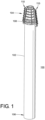
- FIG. 1 illustrates an exemplary auto-locking mast assembly 100 in accordance with the present disclosure.
- the mast assembly 100 generally includes a base section or tube 102 having a top or upper portion 104 and a bottom or lower portion 106.
- a telescoping portion 108 is illustrated as being situated generally adjacent the top or upper portion 104 of the mast assembly 100.
- the telescoping portion 108 could alternatively be situated adjacent the lower portion 106.
- An auto-lock/unlock system 110 is also shown and is generally located on one or both sides of the telescoping portion 108 of the mast assembly 100.
- the telescoping portion 108 of the mast assembly 100 in FIG. 1 is generally composed of a plurality of telescoping mast sections 103a - 103f.
- each of the mast sections 103a, 103b, 103c, 103d, 103e, and 103f is typically telescopically received in the adjacent base section or tube 102.
- the telescoping mast sections can be sealed together such that pressurized air or fluid can be used to extend the telescoping mast sections 103a - 103f out of each other and/or the base section 102.
- the auto-lock/unlock system 110 is illustrated as being located on both sides of the telescoping portion 108 of the mast assembly 100. That is, the auto-lock/unlock system 110 is shown as including a first stack of auto-locking assemblies 112 located on one side of the telescoping portion 108 and a second stack of auto-locking assemblies 114 located on an opposing side of the telescoping portion.
- the auto-lock/unlock system 110 can include any desired number of stacks of auto-locking assemblies.
- the auto-lock/unlock system 110 could include a single stack or two or more stacks of auto-locking assemblies without departing from the scope of the present disclosure.
- the particular number of desired stacks of auto-locking assemblies may depend on, for example, the size of the mast assembly or the weight of any payload that may be attached to the mast assembly, where larger sized masts and heavier payloads may require additional stacks of auto-locking assemblies compared with smaller sized masts and lighter payloads.
- the stacks of auto-locking assemblies 112, 114 each generally include at least one base auto-lock 116 and n - 1 intermediate auto-locks 118, where n is equal to the number of telescoping mast sections included in a given mast assembly.
- five (5) intermediate auto-locks 118a- 118e i.e., 6-1) are provided for telescoping mast sections 103a - 103e.
- Mast section 103f being the last section of telescoping portion 108, does not require an auto-lock because no additional mast section needs to be locked into place above the last section. While each intermediate auto-lock 118a - 118e typically corresponds to a differently sized telescoping mast section 103a - 103e, the features of the intermediate auto-locks are generally identical. Accordingly, only the first intermediate auto-lock 118a will be described in the additional detail illustrations of FIGS. 3 and 5 but it should be appreciated that each of the intermediate auto-locks generally includes the same features.
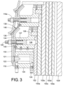
- the first auto-lock in each stack of auto-locking assemblies that may be included in a given mast assembly of the present disclosure is typically a base auto-lock assembly, such as base auto-lock 116 illustrated in FIG. 2 and shown in greater detail in FIGS. 3 and 4 .
- the base auto-lock assembly 116 is attached to the base section or tube 102 and generally includes an actuating cylinder body 120, a collar 126, a latch pin 128, a latch lever 132, a guide plate 134, and a guide bearing 136.
- An electrical actuator (not shown) could also be used in place of the actuating cylinder 120 without departing from the scope of the present disclosure.
- a horizontal bore 121 is centrally located in the cylinder body 120 and is sized to house and permit the back and forth movement of a piston 122.
- An inlet/outlet 124 is fluidically connected to the bore 121 to provide pressurized fluid to and from the bore. The pressurized fluid, when provided to or released from the bore 121, enables the back and forth movement of the piston 122 within the bore.
- the piston 122 is oriented generally perpendicular to the vertically oriented base tube 102 and generally parallel to the horizontally oriented bore 121.
- the force receiving end 122a of the piston 122 is positioned adjacent the base tube 102 and the actuating end 122b is generally disposed adjacent the latch lever 132 and guide plate 134.
- the latch lever 132 and guide plate 134 are oriented generally perpendicular to the horizontally oriented piston 122 and generally parallel to the vertically oriented base tube 102. Moreover, the latch lever 132 and guide plate 134 are generally disposed adjacent to one another, with the guide plate 134 being located closer in distance to the base tube 102. In other words, the latch lever 132 is generally disposed on or adjacent to a surface of the guide plate 134 which faces away from the base tube 102. A thru-hole 135a in the guide plate 134 permits the actuating end 122b of the piston 122 to extend there-through and contact the latch lever 132.
- the guide plate 134 further includes a guide bearing 136 disposed on a top or upper portion 134b, the guide bearing being angled inward toward the base tube 102.
- the guide bearing 136 provides a bearing surface 138 adapted to interact with the latch lever 146 of the intermediate auto-lock assembly 118a (see FIG. 3 ).
- the base collar 126 provides a means for attaching the base auto-lock assembly 116 to the base section or tube 102.
- the base collar 126 is mounted to an upper end of the base tube 102 and has a diameter corresponding to the diameter of the base tube.
- the base collar 126 is generally an annular body adapted to be inserted into an open end of the cylindrical base tube 102 and/or adapted to fit around the diameter of the base tube adjacent an upper, open end thereof.
- the base tube 102 and the base collar 126 can be equipped with fully tapped thru-holes (not shown) around their circumference, the thru-holes of both components being aligned to receive a fastening means (not shown) which secures the base collar to the base tube.
- the base collar 126 can be welded to the base tube 102.
- the base collar 126 can be made of any suitable material such as a metal or composite material.
- the base collar 126 can be made by any suitable manufacturing process or processes such as molding, casting, machining, etc.
- the base collar 126 provides a means for attaching the base auto-lock assembly 116 to the base tube 102.
- the base collar 126 also provides a means for attaching the various components of the base auto-lock assembly 116 to the base collar itself.
- a plurality of countersink bores 129 can be provided in the base collar 126 that are adapted to receive suitable fasteners, such as screws 131 (see FIG. 4 ).
- the countersink bores 129 are generally used for securing the actuating cylinder 120 and guide plate 134 of the auto-lock assembly 116 to the base collar 126.
- the base collar 126 includes a horizontally oriented arm portion 127 to which these components can be attached.
- the arm portion 127 extends a distance away from and generally perpendicular to the vertically oriented base tube section 102 and can include the plurality of countersink bores 129.
- the arm portion 127 of the base collar 126 is also configured to house and permit the back and forth movement of the latch pin 128.
- the latch pin 128 is disposed in a centrally located thru-hole 133 of the arm portion 127 of the base collar 126.
- the latch pin 128 is oriented generally perpendicular to the vertically oriented base tube 102 and generally parallel to the horizontally oriented arm portion 127.
- a locking end 128a of the latch pin 128 is positioned adjacent the base tube 102 and the opposite end 128b is positioned adjacent the latch lever 132 and guide plate 134.
- End 128b also includes a mechanical force generator, such as spring 130, which enables the back and forth movement of the latch pin 128 within the thru-hole 133.
- the latch lever 132 is mounted in front of the spring 130 on end 128b of the latch pin 128, such that the spring is positioned between a step or ledge portion formed in the latch pin 128 and the guide plate 134.
- the mounting arrangement of the latch lever 132 and latch pin 128 creates a pivot point about which the latch pin can rotate inward and outward relative to the base tube 102.
- One or more latch panels 148 are provided in the smaller adjacent telescoping mast section (i.e., 103a) that each include a cutout 156.
- the cutout 156 of each latch panel 148 is configured to receive the locking end 128a of the latch pin 128. More particularly, the spring 130 causes the locking end 128a of the latch pin 128 to engage the cutout 156 on a respective latch panel 148, thereby locking the telescoping mast section 103a into an extended position with respect to base tube 102. This occurs during an extension process when the mast section 103a is telescoping vertically upward from the base tube 102.
- a second thru-hole 135b in the guide plate 134 and a thru-hole 137 in the latch lever 132 permits end 128b of the latch pin 128 to extend there-through.
- thru-holes 135b and 137 permit the latch pin 128 to engage and disengage from the cutout 156 of the latch panel 148.
- the latch pin 128 is generally disposed above the piston 122.
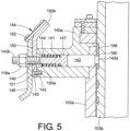
- the intermediate auto-lock assembly 118a is attached to corresponding telescoping mast section 103a and generally includes, an intermediate collar 140a, a latch pin 142, a latch lever 146, a guide plate 150, and a guide bearing 152.
- the latch lever 146 and guide plate 150 are oriented generally perpendicular to the horizontally oriented latch pin 142 and generally parallel to the vertically oriented telescoping mast section 103a.
- the latch lever 146 and guide plate 150 are generally disposed adjacent to one another, with the guide plate being located closer in distance to the telescoping mast section 103a.
- the latch lever 146 is generally disposed on or adjacent to a surface of the guide plate 150 which faces away from the telescoping mast section 103a.
- the guide bearing 152 is disposed on a top or upper portion 150b of the guide plate 150 and is angled inward toward the base tube 102.
- the guide bearing 152 provides a bearing surface 154 adapted to interact with the latch lever of subsequent intermediate auto-lock assembly 118b (see FIG. 2 ).
- the intermediate collar 140a provides a means for attaching the intermediate auto-lock assembly 118a to the base section or tube 102.
- the intermediate collar 140a is mounted to an upper end of telescoping mast section 103a and has a diameter corresponding to the diameter of the telescoping mast section.
- the intermediate collar 140a is generally an annular body adapted to be inserted into an open end of the telescoping mast section 103a and/or adapted to fit around the diameter of the mast section adjacent an upper, open end thereof.
- the telescoping mast section 103a and the base collar 140a can be equipped with fully tapped thru-holes (not shown) around their circumference, the thru-holes of both components being aligned to receive a fastening means (not shown) which secures the intermediate collar to the telescoping mast section.
- the intermediate collar 140a can be welded to telescoping mast section 103a.
- the intermediate collar 140a can be made of any suitable material such as a metal or composite material.
- the intermediate collar 140a can be made by any suitable manufacturing process or processes such as molding, casting, machining, etc.
- the intermediate collar 140a provides a means for attaching the intermediate auto-lock assembly 118a to the telescoping mast section 103a.
- the intermediate collar 140a also provides a means for attaching the various components of the intermediate auto-lock assembly 118a to the collar itself.
- one or more countersink bores 143 can be provided in the intermediate collar 140a that are adapted to receive suitable fasteners, such as screws 145 (see FIG. 5 ).
- the one or more countersink bores 143 are generally used for securing the guide plate 150 of the intermediate auto-lock assembly 118a to the intermediate collar 140a.
- the intermediate collar 140a includes a horizontally oriented arm portion 141 to which the guide plate can be attached.
- the arm portion 141 extends a distance away from and generally perpendicular to the vertically oriented telescoping mast section 103a and can include the one or more countersink bores 143.
- the arm portion 141 of the intermediate collar 140a is also configured to house and permit the back and forth movement of the latch pin 142.
- the latch pin 142 is disposed in a centrally located thru-hole 147 of the arm portion 141 of the intermediate collar 140a.
- the latch pin 142 is oriented generally perpendicular to the vertically oriented telescoping mast section 103a and generally parallel to the horizontally oriented arm portion 141.
- a locking end 142a of the latch pin 142 is positioned adjacent the telescoping mast section 103a and the opposite end 142b is positioned adjacent the latch lever 146 and guide plate 150.
- End 142b also includes a mechanical force generator, such as spring 144, which enables the back and forth movement of the latch pin 142 within the thru-hole 147.
- the latch lever 146 is mounted in front of the spring 144 on end 142b of the latch pin 142, such that the spring is positioned between the telescoping mast section 103a and the guide plate 150.
- the mounting arrangement of the latch 146 and latch pin 142 creates a pivot point about which the latch pin can rotate inward and outward relative to the telescoping mast section 103a.
- One or more latch panels 158 are provided in the subsequent smaller adjacent telescoping mast section (i.e., 103b) that each include a cutout 160.
- the cutout 160 of each latch panel 158 is configured to receive the locking end 142a of the latch pin 142. More particularly, the spring 144 causes the locking end 142a of the latch pin 142 to engage the cutout 160 on a respective latch panel 158, thereby locking the telescoping mast section 103b into an extended position with respect to mast section 103a. This occurs during an extension process when the mast section 103b is telescoping vertically upward from the mast section 103a.
- a thru-hole 149 in the latch lever 146 and a thru-hole 151 in the guide plate 150 permit end 142b of the latch pin 142 to extend there-through.
- thru-holes 149 and 151 permit the latch pin 142 to engage and disengage from the cutout 160 of the latch panel 158.
- the base tube 102 and intermediate telescoping mast section 103a of the mast assembly 100 are illustrated in a nested position.
- the nested position of the base tube 102 and all telescoping mast sections 103a - 103f is also illustrated FIG. 2 .
- the internal pressure of the entire mast i.e., base tube 102 and intermediate sections 103a - 103f
- the first intermediate mast section is increased relative to the outside atmospheric pressure, causing the first intermediate mast section to extend away from the stationary base tube.
- FIG. 1 the internal pressure of the entire mast (i.e., base tube 102 and intermediate sections 103a - 103f) is increased relative to the outside atmospheric pressure, causing the first intermediate mast section to extend away from the stationary base tube.
- the first intermediate tube section 103a reaches its maximum extended height when the latch panel 148 disposed around the outside surface of the first intermediate tube section contacts the base collar 126 the base tube 102.
- latch pin 128 (which is pre-loaded via spring 130) of the base collar 126, engages into the cutout 156 of the latch panel 148 on the first intermediate tube section 103a, thereby locking the telescoping mast section 103a into an extended position with respect to base tube 102.
- the second intermediate tube section 103b reaches its maximum extended height when the latch panel 158 disposed around the outside surface of the second intermediate tube section contacts the intermediate collar 140a of the first intermediate mast section 103a.
- latch pin 142 (which is pre-loaded via spring 144) of the intermediate collar 140a, engages into the cutout 160 of the latch panel 158 on the second intermediate tube section 103b, thereby locking the second intermediate tube section into an extended position with respect to first mast section 103a.
- the latch pins from each intermediate collar assembly (140a - 140f) will be engaged into the cutouts of the latch panel of the next smaller adjacent tube section.
- the internal pressure of the mast assembly 100 can then be reduced to atmospheric pressure as positive contact between the latch pins and tube section's latch panels will keep the mast extended.
- the internal pressure of the entire mast i.e., base tube 102 and intermediate sections 103a - 103f
- the air cylinder 120 mounted to the base collar 126 are then actuated. More particularly, when the piston 122 of the air cylinder 120 contacts the latch lever 132 on the base collar 126, the pivot point created by the mounting arrangement between the latch lever and the latch pin 128 permits the latch lever to rotate outward relative to the first intermediate tube section 103a.
- the latch lever 146 on the intermediate collar 140a of the unlocked first intermediate tube section 103a contacts the guide plate 134 and guide bearing 136 of the base collar 126.
- the contact between the latch lever 146 and the guide bearing 136 of the guide plate 134 actuates the latch pin 142. More particularly, when the latch lever 146 contacts the guide bearing 136 of the guide plate 134, the pivot point created by the mounting arrangement between the latch lever and the latch pin 142 permits the latch lever to rotate. Due to the guide plate 134 being oriented at an angle, contact between the latch lever 142 and guide bearing 136 causes the latch lever to rotate outward relative to the second intermediate tube section 103b.
- the latch lever on the second intermediate collar 140b of the unlocked second intermediate tube section 103b contacts the guide plate 150 and guide bearing 152 of the first intermediate collar 140a.
- the contact between the latch lever and the guide bearing 152 of the guide plate 150 actuates the latch pin of the second intermediate collar 140b. More particularly, when the latch lever of the second intermediate collar 140b contacts the guide bearing 152 of the guide plate 150, the pivot point created by the mounting arrangement between the latch lever and the latch pin permits the latch lever to rotate. Due to the guide plate 150 being oriented at an angle, contact between the latch lever and guide bearing 152 causes the latch lever to rotate outward relative to the third intermediate tube section 103c.
- This rotational motion of the latch lever pulls the latch pin linearly away from the third intermediate tube section 103c, overcomes the force exerted by the associated spring, and causes the associated latch pin to disengage the respective latch penal cutout on the third intermediate tube section.
- the third intermediate tube section 103c now unlocked from the second intermediate tube section 103b, begins to retract. As retraction continues, the locking pins of each intermediate collar are disengaged from the latch panel cutouts of the next smaller adjacent intermediate tube section. This is repeated until all locking pins are actuated and the mast assembly 100 is fully unlocked and retracted.
- the exemplary auto-locking mast assembly described in the present disclosure provides many advantages over telescoping mast assemblies currently known in the art.
- the mast unlocking method described herein, and more particularly, the initial step of unlocking the mast can be easily remotely controlled. That is, a user is not required to contact/touch the mast in order to lock/unlock the mast.
- the positive contact between adjacent collar components is automatically unlocked between intermediate and top mast sections during retraction, thereby decreasing the overall time it takes to retract the mast assembly.
- the pre-loaded latch pins described herein automatically lock into place at the end of mast section travel, thereby decreasing the overall time it takes to fully extend the mast assembly.
- the locking pins described herein are a simple latch pin design which provide for optimal manufacturability and reduced cost thereof.
- the automated locking and unlocking of the exemplary mast assembly described herein reduces or even eliminates water and dust ingress pathways.
Landscapes
- Engineering & Computer Science (AREA)
- Architecture (AREA)
- General Engineering & Computer Science (AREA)
- Mechanical Engineering (AREA)
- Civil Engineering (AREA)
- Structural Engineering (AREA)
- Quick-Acting Or Multi-Walled Pipe Joints (AREA)
- Lock And Its Accessories (AREA)
- Jib Cranes (AREA)
- Mutual Connection Of Rods And Tubes (AREA)
- Forklifts And Lifting Vehicles (AREA)
Claims (17)
- Teleskopmastanordnung (100) mit einer Vielzahl von Teleskoprohrabschnitten (102, 103), die zwischen einer zurückgezogenen Position und einer ausgefahrenen Position konfigurierbar sind, wobei mindestens einer der Teleskoprohrabschnitte mit einer Selbstverriegelungsanordnung (114) versehen ist, wobei die Anordnung umfasst:einen ersten Sperrstift (142), der rechtwinklig zu einem ersten Rohrabschnitt (103a) angebracht ist, wobei der erste Sperrstift in eine verriegelte Position mit einem zweiten Rohrabschnitt (103b) vorgespannt und dazu ausgelegt ist, sich linear in eine entriegelte Position in Bezug auf den zweiten Rohrabschnitt (103b) zu bewegen;einen ersten Sperrhebel (146), der an dem ersten Sperrstift (142) angebracht ist, wobei der erste Sperrhebel dazu ausgelegt ist, zwischen einer parallelen Position und einer gedrehten Position in Bezug auf den ersten Rohrabschnitt (103a) zu schwenken;eine Führungsplatte (134), die an einem dritten Rohrabschnitt (102) angebracht ist, und eine abgewinkelte Auflagefläche (138), die an einem oberen Abschnitt der Führungsplatte (134) angeordnet ist, wobei die Führungsplatte und die abgewinkelte Auflagefläche dazu ausgelegt sind, den ersten Sperrhebel (146) zu berühren;wobei der erste Sperrstift (142) vorgespannt ist, um sich mit dem zweiten Rohrabschnitt (103b) linear in die verriegelte Position zu bewegen, wenn sich der zweite Rohrabschnitt (103b) in der ausgefahrenen Position in Bezug auf den ersten Rohrabschnitt (103a) befindet,wobei sich der erste Sperrstift (142) durch die Schwenkbewegung des ersten Sperrhebels (146) linear aus der verriegelten Position in die entriegelte Position bewegt und der erste Sperrhebel (146) durch den Kontakt mit der abgewinkelten Auflagefläche (138) der Führungsplatte (134) aus der parallelen Position in die gedrehte Position schwenkt, wenn sich der erste Rohrabschnitt (103a) in der zurückgezogenen Position in Bezug auf den dritten Rohrabschnitt (102) befindet, um dadurch die zurückgezogene Position des zweiten Rohrabschnitts (103b) in Bezug auf den ersten Rohrabschnitt (103a) zu ermöglichen.
- Teleskopmastanordnung nach Anspruch 1, wobei der dritte Rohrabschnitt ein Basisrohr (102), der erste Rohrabschnitt eine Vielzahl von Zwischenrohren (103a-e) und der zweite Rohrabschnitt ein Endrohr (103f) ist.
- Teleskopmastanordnung nach Anspruch 1 oder 2, ferner umfassend eine erste Sperrplatte (158), die an dem zweiten Rohrabschnitt (103b) angeordnet und dazu ausgelegt ist, wenn sie sich in der verriegelten Position befindet, den ersten Sperrstift (142) aufzunehmen.
- Teleskopmastanordnung nach einem der Ansprüche 1 bis 3, ferner umfassend einen Kragen (126; 140), der dazu ausgelegt ist, die Selbstverriegelungsanordnung an einem der Teleskoprohrabschnitte (102; 130a-e) in der Vielzahl von Teleskoprohrabschnitten zu anzubringen.
- Teleskopmastanordnung nach einem der Ansprüche 1 bis 4, ferner umfassend:einen zweiten Sperrstift (128), der rechtwinklig zu dem dritten Rohrabschnitt (102) angebracht ist, wobei der zweite Sperrstift in eine verriegelte Position mit dem ersten Rohrabschnitt (103a) vorgespannt und dazu ausgelegt ist, sich linear in eine entriegelte Position in Bezug auf den ersten Rohrabschnitt (103a) zu bewegen;einen zweiten Sperrhebel (132), der an dem zweiten Sperrstift (128) angebracht ist, wobei der zweite Sperrhebel dazu ausgelegt ist, zwischen einer parallelen Position und einer gedrehten Position in Bezug auf den dritten Rohrabschnitt (102) zu schwenken; undeinen Kolben (122), der unterhalb des zweiten Sperrstifts (128) angeordnet und rechtwinklig zu dem dritten Rohrabschnitt (102) angebracht ist, wobei der Kolben dazu ausgelegt ist, sich linear zu bewegen, um den zweiten Sperrhebel (132) zu betätigen.
- Teleskopmastanordnung nach Anspruch 5, wobei sich der zweite Sperrstift (128) durch die Schwenkbewegung des zweiten Sperrhebels (132) linear aus der verriegelten Position in die entriegelte Position zu bewegen und der zweite Sperrhebel durch die lineare Bewegung des Kolbens (122) aus der parallelen Position in die gedrehte Position zu schwenken, um dadurch die eingezogene Position des ersten Rohrabschnitts (103a) in Bezug auf den dritten Rohrabschnitt (102) zu ermöglichen.
- Teleskopmastanordnung nach Anspruch 5 oder 6, ferner umfassend eine zweite Sperrplatte (148), die an dem ersten Rohrabschnitt (103a) angeordnet und dazu ausgelegt ist, wenn sie sich in der verriegelten Position befindet, den zweiten Sperrstift (128) aufzunehmen.
- Teleskopmastanordnung nach einem der Ansprüche 1 bis 7, wobei der Sperrstift (142; 128) federaktiviert ist.
- Teleskopmastanordnung nach Anspruch 1, wobei
die Vielzahl von Teleskopmastabschnitten (102, 103) ein Basisrohr (102), ein Zwischenrohr (103a-e) und ein Endrohr (103b-f) umfassen, wobei das Zwischenrohr und das Endrohr dazu angepasst sind, teleskopisch in dem Basisrohr aufgenommen zu werden; ferner umfassend:eine Basisselbstverriegelung (116) mit einem Kragen (126) zum Anbringen an dem Basisrohr (102) und eine Zwischenselbstverriegelung (118) mit einem Kragen (140a-e) zum Anbringen an dem Zwischenrohr (103a-e);wobei sowohl die Basisselbstverriegelung als auch die Zwischenselbstverriegelung enthalten:einen Sperrstift (128; 142), der in dem Kragen untergebracht und dazu ausgelegt ist, sich linear zwischen einer verriegelten und einer entriegelten Position zu bewegen;einen Sperrhebel (132; 146), der an dem Sperrstift angebracht und dazu ausgelegt ist, zwischen einer parallelen Position und einer gedrehten Position in Bezug auf die Vielzahl von Teleskopmastabschnitten zu schwenken;eine Führungsplatte (134; 150), die auf dem Kragen angebracht ist;wobei der Sperrstift (128) der Basisselbstverriegelung in die verriegelte Position mit dem Zwischenrohr (103a) bewegbar ist, wenn das Zwischenrohr aus dem Basisrohr (102) herausgezogen ist;wobei der Sperrstift (142) der Zwischenselbstverriegelung in die verriegelte Position mit dem Endrohr (103f) bewegbar ist, wenn das Endrohr aus dem Zwischenrohr (103e) herausgezogen ist, und in die entriegelte Position mit dem Endrohr bewegbar ist, wenn der Sperrstift der Zwischenselbstverriegelung aus der parallelen Position in die gedrehte Position durch Kontakt mit der Führungsplatte der Basisselbstverriegelung schwenkt, wenn das Zwischenrohr in das Basisrohr zurückgezogen ist, wodurch sich das Endrohr in das Zwischenrohr zurückziehen kann. - Teleskopmastanordnung nach Anspruch 9, ferner umfassend:einen Kolben (122), der in dem Kragen (126) der Basisselbstverriegelung unterhalb des Sperrstifts (128) untergebracht und dazu ausgelegt ist, sich linear zu bewegen, um den Sperrhebel (132) der Basisselbstverriegelung zu betätigen,wobei der Sperrstift (128) der Basisselbstverriegelung in die entriegelte Position mit dem Zwischenrohr (103a-e) bewegbar ist, wenn der Sperrhebel der Basisselbstverriegelung durch die lineare Bewegung des Kolbens (122) aus der parallelen Position in die gedrehte Position schwenkt, wodurch sich das Zwischenrohr in das Basisrohr (102) zurückziehen kann.
- Teleskopmastanordnung nach Anspruch 9 oder 10 ferner umfassend eine Sperrplatte (148), die auf dem Zwischenrohr angeordnet und dazu ausgelegt ist, in der verriegelten Position den Sperrstift (128) der Basisselbstverriegelung aufzunehmen.
- Teleskopmastanordnung nach einem der Ansprüche 9 bis 11, ferner umfassend eine Sperrplatte (158), die auf dem Endrohr (103f) angeordnet und dazu ausgelegt ist, in der verriegelten Position den Sperrstift (142) der Zwischenselbstverriegelung aufzunehmen.
- Teleskopmastanordnung nach einem der Ansprüche 9 bis 12, wobei die Sperrstifte (128, 142) sowohl der Basisals auch der Zwischenselbstverriegelung federaktiviert sind.
- Teleskopmastanordnung nach einem der Ansprüche 9 bis 13, wobei die Basisselbstverriegelung (116) eine erste Basisselbstverriegelung, die auf einer Seite des Kragens angeordnet ist, und eine zweite Basisselbstverriegelung umfasst, die auf einer gegenüberliegenden Seite des Kragens angeordnet ist.
- Teleskopmastanordnung nach einem der Ansprüche 9 bis 14, wobei die Zwischenselbstverriegelung (118) eine erste Zwischenselbstverriegelung, die auf einer Seite des Kragens angeordnet ist, und eine zweite Zwischenselbstverriegelung umfasst, die auf einer gegenüberliegenden Seite des Kragens angeordnet ist.
- Teleskopmastanordnung nach einem der Ansprüche 9 bis 15, wobei das Zwischenrohr eine Vielzahl von Zwischenrohren (103ae) umfasst und die Zwischenselbstverriegelung (118) eine Vielzahl von Zwischenselbstverriegelungen (118a-e) umfasst, die jeweils einen Kragen zum Anbringen an einem Zwischenrohr in der Vielzahl der Zwischenrohre aufweisen.
- Teleskopmastanordnung nach Anspruch 16, wobei jede Zwischenselbstverriegelung in der Vielzahl von Zwischenselbstverriegelungen eine erste Zwischenselbstverriegelung, die auf einer Seite des Kragens angeordnet ist, und eine zweite Zwischenselbstverriegelung umfasst, die auf einer gegenüberliegenden Seite des Kragens angeordnet ist.
Applications Claiming Priority (2)
| Application Number | Priority Date | Filing Date | Title |
|---|---|---|---|
| US201862680776P | 2018-06-05 | 2018-06-05 | |
| PCT/US2019/035364 WO2019236561A1 (en) | 2018-06-05 | 2019-06-04 | Auto-locking telescoping mast |
Publications (2)
| Publication Number | Publication Date |
|---|---|
| EP3802994A1 EP3802994A1 (de) | 2021-04-14 |
| EP3802994B1 true EP3802994B1 (de) | 2024-09-25 |
Family
ID=67002399
Family Applications (1)
| Application Number | Title | Priority Date | Filing Date |
|---|---|---|---|
| EP19732819.8A Active EP3802994B1 (de) | 2018-06-05 | 2019-06-04 | Selbstverriegelnder teleskopmast |
Country Status (9)
| Country | Link |
|---|---|
| US (1) | US11118372B2 (de) |
| EP (1) | EP3802994B1 (de) |
| JP (1) | JP7198567B2 (de) |
| KR (1) | KR102572380B1 (de) |
| AU (1) | AU2019282610B2 (de) |
| CA (1) | CA3101208C (de) |
| RU (1) | RU2756640C1 (de) |
| UA (1) | UA125678C2 (de) |
| WO (1) | WO2019236561A1 (de) |
Families Citing this family (6)
| Publication number | Priority date | Publication date | Assignee | Title |
|---|---|---|---|---|
| GB2582249B (en) * | 2019-01-25 | 2023-07-05 | South Midlands Communications Ltd | Telescopic mast |
| US20220136545A1 (en) * | 2019-06-10 | 2022-05-05 | Grovist Innovations Llc | System with vertically adjustable telescoping pole assembly and cramp brake mechanism |
| IT202000004345A1 (it) * | 2020-03-02 | 2021-09-02 | Fireco S R L A Socio Unico | Assieme colonna telescopica pneumatica |
| US12509902B2 (en) * | 2020-07-03 | 2025-12-30 | Fireco S.R.L. A Socio Unico | Pneumatic telescopic mast |
| WO2022049332A1 (fr) * | 2020-09-04 | 2022-03-10 | Airbus Defence And Space Sas | Mât télescopique spatial |
| US12288921B2 (en) * | 2022-08-17 | 2025-04-29 | Quanta Computer Inc. | Smart pole assembly |
Citations (1)
| Publication number | Priority date | Publication date | Assignee | Title |
|---|---|---|---|---|
| US9670948B1 (en) * | 2016-01-27 | 2017-06-06 | The Will-Burt Company | Latch for sequentially extended mechanical mast |
Family Cites Families (22)
| Publication number | Priority date | Publication date | Assignee | Title |
|---|---|---|---|---|
| US2708493A (en) * | 1949-07-23 | 1955-05-17 | Thomas Mold & Die Co | Portable antenna mast |
| US2795303A (en) * | 1952-12-26 | 1957-06-11 | Benjamin H Muehlhause | Masts or towers |
| US3047107A (en) * | 1957-11-25 | 1962-07-31 | Alpar Mfg Company | Telescoping tower |
| SU141186A1 (ru) * | 1960-03-31 | 1960-11-30 | Е.П. Артеменко | Телескопическа мачта |
| US3688455A (en) * | 1970-10-23 | 1972-09-05 | Sanders Associates Inc | Telescoping support with double acting piston and latch and retaining means |
| JPS62180148A (ja) | 1986-02-04 | 1987-08-07 | Kubota Ltd | 車輪形トラクタの走行系動力伝達装置 |
| JPH0617957Y2 (ja) * | 1986-05-08 | 1994-05-11 | 株式会社名工社 | 伸縮ポ−ル |
| DE3708326C1 (de) * | 1987-03-14 | 1988-05-11 | Dornier Gmbh | Teleskopartig Iaengenveraenderliche Einrichtung |
| SU1530556A1 (ru) * | 1987-11-11 | 1989-12-23 | Всесоюзный Государственный Конструкторско-Технологический Институт "Вктистроймеханизация" | Телескопическа мачта подъемника |
| SU1626287A1 (ru) * | 1989-03-23 | 1991-02-07 | Предприятие П/Я В-2634 | Телескопическа мачта и замок секции телескопической мачты |
| DE4344795A1 (de) * | 1993-12-28 | 1995-06-29 | Liebherr Werk Ehingen | Fahrbarer Kran mit einem Teleskopausleger |
| JP3047093B2 (ja) * | 1995-06-27 | 2000-05-29 | 和光機械工業株式会社 | 投光機 |
| DE19811813B4 (de) * | 1998-03-18 | 2005-11-24 | Grove U.S. LLC (n.d.Ges.d.Staates Delaware) | Seitliche Auslegerverriegelung |
| DE10022373B4 (de) * | 2000-05-08 | 2005-11-24 | Grove U.S. Llc | Verriegelungs- und Betätigungseinheit für seitliche Auslegerverriegelung |
| US6601719B2 (en) * | 2001-09-21 | 2003-08-05 | Link-Belt Construction Equipment Co., L.P., Lllp | Locking and latching system for a telescoping boom |
| US6767115B2 (en) * | 2001-11-16 | 2004-07-27 | The Will-Burt Company | Pneumatic telescoping mast |
| US7430890B1 (en) * | 2005-06-24 | 2008-10-07 | Vincent P Battaglia | Telescoping tower and method of manufacture |
| US8234823B2 (en) * | 2008-07-09 | 2012-08-07 | Mcclure Clifton D | Telescoping mast |
| DE102009009944B4 (de) * | 2009-02-20 | 2011-02-24 | Terex-Demag Gmbh | Sicherungs- und Verbolzungseinheit |
| US9637358B2 (en) * | 2010-12-17 | 2017-05-02 | Tadano Faun Gmbh | Mobile telescopic crane |
| EP3138805B1 (de) * | 2014-05-20 | 2020-08-05 | Xuzhou Heavy Machinery Co., Ltd. | Einzylinderbolzendehnvorrichtung und -kran |
| US9520642B2 (en) * | 2015-04-10 | 2016-12-13 | The Will-Burt Company | Pneumatic non-locking low-profile telescoping masts |
-
2019
- 2019-06-04 EP EP19732819.8A patent/EP3802994B1/de active Active
- 2019-06-04 KR KR1020217000007A patent/KR102572380B1/ko active Active
- 2019-06-04 UA UAA202008367A patent/UA125678C2/uk unknown
- 2019-06-04 RU RU2020143343A patent/RU2756640C1/ru active
- 2019-06-04 JP JP2020567569A patent/JP7198567B2/ja active Active
- 2019-06-04 AU AU2019282610A patent/AU2019282610B2/en active Active
- 2019-06-04 US US16/430,965 patent/US11118372B2/en active Active
- 2019-06-04 WO PCT/US2019/035364 patent/WO2019236561A1/en not_active Ceased
- 2019-06-04 CA CA3101208A patent/CA3101208C/en active Active
Patent Citations (1)
| Publication number | Priority date | Publication date | Assignee | Title |
|---|---|---|---|---|
| US9670948B1 (en) * | 2016-01-27 | 2017-06-06 | The Will-Burt Company | Latch for sequentially extended mechanical mast |
Also Published As
| Publication number | Publication date |
|---|---|
| US20190368216A1 (en) | 2019-12-05 |
| CA3101208C (en) | 2023-10-17 |
| JP7198567B2 (ja) | 2023-01-04 |
| UA125678C2 (uk) | 2022-05-11 |
| KR102572380B1 (ko) | 2023-09-01 |
| CA3101208A1 (en) | 2019-12-12 |
| RU2756640C1 (ru) | 2021-10-04 |
| KR20210035163A (ko) | 2021-03-31 |
| BR112020023017A2 (pt) | 2021-02-02 |
| EP3802994A1 (de) | 2021-04-14 |
| AU2019282610B2 (en) | 2023-01-19 |
| AU2019282610A1 (en) | 2020-12-03 |
| JP2021533286A (ja) | 2021-12-02 |
| US11118372B2 (en) | 2021-09-14 |
| WO2019236561A1 (en) | 2019-12-12 |
Similar Documents
| Publication | Publication Date | Title |
|---|---|---|
| EP3802994B1 (de) | Selbstverriegelnder teleskopmast | |
| EP2268566B1 (de) | Integrierte keilverriegelungsanordnung | |
| US12134923B2 (en) | Mechanically damped pull then lift hold open rod mechanism | |
| US9090438B2 (en) | Locking and bolting unit | |
| WO2006098739A2 (en) | Heavy duty field mast | |
| AU2016389907B2 (en) | Latch for sequentially extended mechanical mast | |
| EP1922490B1 (de) | Mechanische aussenverriegelung für einen linearantrieb | |
| US11255101B2 (en) | Mobile tower system | |
| EP3369690B1 (de) | Auslegerkopplungssystem zur auslegerverstauung | |
| CN118560692A (zh) | 一种用于无人机起落架舱门的锁闭机构以及舱门系统 | |
| KR19990071906A (ko) | 승강기 인터로킹 기구 | |
| BR112020023017B1 (pt) | Montagem de bloqueio automático para um mastro telescópico e bloqueio automático para uso com um mastro telescópico | |
| US7207419B2 (en) | Safety lock system for a lift | |
| US5134896A (en) | Roller linkage | |
| US20240217786A1 (en) | Locking head | |
| JPH02273049A (ja) | 電動式アクチュエータ | |
| RU88714U1 (ru) | Телескопическая мачта | |
| CN117175127A (zh) | 电池包的连接机构、车辆以及电池包的拆装机构 | |
| CN119976642A (zh) | 安全顶升控制系统 |
Legal Events
| Date | Code | Title | Description |
|---|---|---|---|
| STAA | Information on the status of an ep patent application or granted ep patent |
Free format text: STATUS: UNKNOWN |
|
| STAA | Information on the status of an ep patent application or granted ep patent |
Free format text: STATUS: THE INTERNATIONAL PUBLICATION HAS BEEN MADE |
|
| PUAI | Public reference made under article 153(3) epc to a published international application that has entered the european phase |
Free format text: ORIGINAL CODE: 0009012 |
|
| STAA | Information on the status of an ep patent application or granted ep patent |
Free format text: STATUS: REQUEST FOR EXAMINATION WAS MADE |
|
| 17P | Request for examination filed |
Effective date: 20210111 |
|
| AK | Designated contracting states |
Kind code of ref document: A1 Designated state(s): AL AT BE BG CH CY CZ DE DK EE ES FI FR GB GR HR HU IE IS IT LI LT LU LV MC MK MT NL NO PL PT RO RS SE SI SK SM TR |
|
| AX | Request for extension of the european patent |
Extension state: BA ME |
|
| DAV | Request for validation of the european patent (deleted) | ||
| DAX | Request for extension of the european patent (deleted) | ||
| RAP3 | Party data changed (applicant data changed or rights of an application transferred) |
Owner name: THE WILL-BURT COMPANY |
|
| STAA | Information on the status of an ep patent application or granted ep patent |
Free format text: STATUS: EXAMINATION IS IN PROGRESS |
|
| 17Q | First examination report despatched |
Effective date: 20220217 |
|
| RIN1 | Information on inventor provided before grant (corrected) |
Inventor name: MAST, REXFORD RICHARD Inventor name: YOUNG, CAMERON JAY Inventor name: FEI, NG KAH |
|
| GRAP | Despatch of communication of intention to grant a patent |
Free format text: ORIGINAL CODE: EPIDOSNIGR1 |
|
| STAA | Information on the status of an ep patent application or granted ep patent |
Free format text: STATUS: GRANT OF PATENT IS INTENDED |
|
| INTG | Intention to grant announced |
Effective date: 20240417 |
|
| GRAS | Grant fee paid |
Free format text: ORIGINAL CODE: EPIDOSNIGR3 |
|
| GRAA | (expected) grant |
Free format text: ORIGINAL CODE: 0009210 |
|
| STAA | Information on the status of an ep patent application or granted ep patent |
Free format text: STATUS: THE PATENT HAS BEEN GRANTED |
|
| AK | Designated contracting states |
Kind code of ref document: B1 Designated state(s): AL AT BE BG CH CY CZ DE DK EE ES FI FR GB GR HR HU IE IS IT LI LT LU LV MC MK MT NL NO PL PT RO RS SE SI SK SM TR |
|
| REG | Reference to a national code |
Ref country code: GB Ref legal event code: FG4D |
|
| REG | Reference to a national code |
Ref country code: CH Ref legal event code: EP |
|
| REG | Reference to a national code |
Ref country code: DE Ref legal event code: R096 Ref document number: 602019059420 Country of ref document: DE |
|
| REG | Reference to a national code |
Ref country code: IE Ref legal event code: FG4D |
|
| REG | Reference to a national code |
Ref country code: LT Ref legal event code: MG9D |
|
| PG25 | Lapsed in a contracting state [announced via postgrant information from national office to epo] |
Ref country code: NO Free format text: LAPSE BECAUSE OF FAILURE TO SUBMIT A TRANSLATION OF THE DESCRIPTION OR TO PAY THE FEE WITHIN THE PRESCRIBED TIME-LIMIT Effective date: 20241225 |
|
| PG25 | Lapsed in a contracting state [announced via postgrant information from national office to epo] |
Ref country code: GR Free format text: LAPSE BECAUSE OF FAILURE TO SUBMIT A TRANSLATION OF THE DESCRIPTION OR TO PAY THE FEE WITHIN THE PRESCRIBED TIME-LIMIT Effective date: 20241226 Ref country code: FI Free format text: LAPSE BECAUSE OF FAILURE TO SUBMIT A TRANSLATION OF THE DESCRIPTION OR TO PAY THE FEE WITHIN THE PRESCRIBED TIME-LIMIT Effective date: 20240925 |
|
| PG25 | Lapsed in a contracting state [announced via postgrant information from national office to epo] |
Ref country code: BG Free format text: LAPSE BECAUSE OF FAILURE TO SUBMIT A TRANSLATION OF THE DESCRIPTION OR TO PAY THE FEE WITHIN THE PRESCRIBED TIME-LIMIT Effective date: 20240925 |
|
| PG25 | Lapsed in a contracting state [announced via postgrant information from national office to epo] |
Ref country code: LV Free format text: LAPSE BECAUSE OF FAILURE TO SUBMIT A TRANSLATION OF THE DESCRIPTION OR TO PAY THE FEE WITHIN THE PRESCRIBED TIME-LIMIT Effective date: 20240925 |
|
| PG25 | Lapsed in a contracting state [announced via postgrant information from national office to epo] |
Ref country code: RS Free format text: LAPSE BECAUSE OF FAILURE TO SUBMIT A TRANSLATION OF THE DESCRIPTION OR TO PAY THE FEE WITHIN THE PRESCRIBED TIME-LIMIT Effective date: 20241225 |
|
| REG | Reference to a national code |
Ref country code: NL Ref legal event code: MP Effective date: 20240925 |
|
| PG25 | Lapsed in a contracting state [announced via postgrant information from national office to epo] |
Ref country code: RS Free format text: LAPSE BECAUSE OF FAILURE TO SUBMIT A TRANSLATION OF THE DESCRIPTION OR TO PAY THE FEE WITHIN THE PRESCRIBED TIME-LIMIT Effective date: 20241225 Ref country code: NO Free format text: LAPSE BECAUSE OF FAILURE TO SUBMIT A TRANSLATION OF THE DESCRIPTION OR TO PAY THE FEE WITHIN THE PRESCRIBED TIME-LIMIT Effective date: 20241225 Ref country code: LV Free format text: LAPSE BECAUSE OF FAILURE TO SUBMIT A TRANSLATION OF THE DESCRIPTION OR TO PAY THE FEE WITHIN THE PRESCRIBED TIME-LIMIT Effective date: 20240925 Ref country code: GR Free format text: LAPSE BECAUSE OF FAILURE TO SUBMIT A TRANSLATION OF THE DESCRIPTION OR TO PAY THE FEE WITHIN THE PRESCRIBED TIME-LIMIT Effective date: 20241226 Ref country code: FI Free format text: LAPSE BECAUSE OF FAILURE TO SUBMIT A TRANSLATION OF THE DESCRIPTION OR TO PAY THE FEE WITHIN THE PRESCRIBED TIME-LIMIT Effective date: 20240925 Ref country code: BG Free format text: LAPSE BECAUSE OF FAILURE TO SUBMIT A TRANSLATION OF THE DESCRIPTION OR TO PAY THE FEE WITHIN THE PRESCRIBED TIME-LIMIT Effective date: 20240925 |
|
| REG | Reference to a national code |
Ref country code: AT Ref legal event code: MK05 Ref document number: 1726745 Country of ref document: AT Kind code of ref document: T Effective date: 20240925 |
|
| PG25 | Lapsed in a contracting state [announced via postgrant information from national office to epo] |
Ref country code: NL Free format text: LAPSE BECAUSE OF FAILURE TO SUBMIT A TRANSLATION OF THE DESCRIPTION OR TO PAY THE FEE WITHIN THE PRESCRIBED TIME-LIMIT Effective date: 20240925 |
|
| PG25 | Lapsed in a contracting state [announced via postgrant information from national office to epo] |
Ref country code: PT Free format text: LAPSE BECAUSE OF FAILURE TO SUBMIT A TRANSLATION OF THE DESCRIPTION OR TO PAY THE FEE WITHIN THE PRESCRIBED TIME-LIMIT Effective date: 20250127 Ref country code: IS Free format text: LAPSE BECAUSE OF FAILURE TO SUBMIT A TRANSLATION OF THE DESCRIPTION OR TO PAY THE FEE WITHIN THE PRESCRIBED TIME-LIMIT Effective date: 20250125 |
|
| PG25 | Lapsed in a contracting state [announced via postgrant information from national office to epo] |
Ref country code: RO Free format text: LAPSE BECAUSE OF FAILURE TO SUBMIT A TRANSLATION OF THE DESCRIPTION OR TO PAY THE FEE WITHIN THE PRESCRIBED TIME-LIMIT Effective date: 20240925 Ref country code: SM Free format text: LAPSE BECAUSE OF FAILURE TO SUBMIT A TRANSLATION OF THE DESCRIPTION OR TO PAY THE FEE WITHIN THE PRESCRIBED TIME-LIMIT Effective date: 20240925 |
|
| PG25 | Lapsed in a contracting state [announced via postgrant information from national office to epo] |
Ref country code: ES Free format text: LAPSE BECAUSE OF FAILURE TO SUBMIT A TRANSLATION OF THE DESCRIPTION OR TO PAY THE FEE WITHIN THE PRESCRIBED TIME-LIMIT Effective date: 20240925 |
|
| PG25 | Lapsed in a contracting state [announced via postgrant information from national office to epo] |
Ref country code: EE Free format text: LAPSE BECAUSE OF FAILURE TO SUBMIT A TRANSLATION OF THE DESCRIPTION OR TO PAY THE FEE WITHIN THE PRESCRIBED TIME-LIMIT Effective date: 20240925 Ref country code: AT Free format text: LAPSE BECAUSE OF FAILURE TO SUBMIT A TRANSLATION OF THE DESCRIPTION OR TO PAY THE FEE WITHIN THE PRESCRIBED TIME-LIMIT Effective date: 20240925 |
|
| PG25 | Lapsed in a contracting state [announced via postgrant information from national office to epo] |
Ref country code: CZ Free format text: LAPSE BECAUSE OF FAILURE TO SUBMIT A TRANSLATION OF THE DESCRIPTION OR TO PAY THE FEE WITHIN THE PRESCRIBED TIME-LIMIT Effective date: 20240925 Ref country code: PL Free format text: LAPSE BECAUSE OF FAILURE TO SUBMIT A TRANSLATION OF THE DESCRIPTION OR TO PAY THE FEE WITHIN THE PRESCRIBED TIME-LIMIT Effective date: 20240925 |
|
| PG25 | Lapsed in a contracting state [announced via postgrant information from national office to epo] |
Ref country code: SK Free format text: LAPSE BECAUSE OF FAILURE TO SUBMIT A TRANSLATION OF THE DESCRIPTION OR TO PAY THE FEE WITHIN THE PRESCRIBED TIME-LIMIT Effective date: 20240925 |
|
| REG | Reference to a national code |
Ref country code: DE Ref legal event code: R097 Ref document number: 602019059420 Country of ref document: DE |
|
| PGFP | Annual fee paid to national office [announced via postgrant information from national office to epo] |
Ref country code: DE Payment date: 20250509 Year of fee payment: 7 |
|
| PG25 | Lapsed in a contracting state [announced via postgrant information from national office to epo] |
Ref country code: DK Free format text: LAPSE BECAUSE OF FAILURE TO SUBMIT A TRANSLATION OF THE DESCRIPTION OR TO PAY THE FEE WITHIN THE PRESCRIBED TIME-LIMIT Effective date: 20240925 |
|
| PGFP | Annual fee paid to national office [announced via postgrant information from national office to epo] |
Ref country code: GB Payment date: 20250508 Year of fee payment: 7 |
|
| PGFP | Annual fee paid to national office [announced via postgrant information from national office to epo] |
Ref country code: FR Payment date: 20250512 Year of fee payment: 7 |
|
| PGFP | Annual fee paid to national office [announced via postgrant information from national office to epo] |
Ref country code: TR Payment date: 20250522 Year of fee payment: 7 |
|
| PLBE | No opposition filed within time limit |
Free format text: ORIGINAL CODE: 0009261 |
|
| STAA | Information on the status of an ep patent application or granted ep patent |
Free format text: STATUS: NO OPPOSITION FILED WITHIN TIME LIMIT |
|
| 26N | No opposition filed |
Effective date: 20250626 |
|
| PG25 | Lapsed in a contracting state [announced via postgrant information from national office to epo] |
Ref country code: SE Free format text: LAPSE BECAUSE OF FAILURE TO SUBMIT A TRANSLATION OF THE DESCRIPTION OR TO PAY THE FEE WITHIN THE PRESCRIBED TIME-LIMIT Effective date: 20240925 |
|
| PGFP | Annual fee paid to national office [announced via postgrant information from national office to epo] |
Ref country code: IT Payment date: 20250610 Year of fee payment: 7 |
|
| PG25 | Lapsed in a contracting state [announced via postgrant information from national office to epo] |
Ref country code: HR Free format text: LAPSE BECAUSE OF FAILURE TO SUBMIT A TRANSLATION OF THE DESCRIPTION OR TO PAY THE FEE WITHIN THE PRESCRIBED TIME-LIMIT Effective date: 20240925 |
|
| REG | Reference to a national code |
Ref country code: CH Ref legal event code: H13 Free format text: ST27 STATUS EVENT CODE: U-0-0-H10-H13 (AS PROVIDED BY THE NATIONAL OFFICE) Effective date: 20260127 |
|
| PG25 | Lapsed in a contracting state [announced via postgrant information from national office to epo] |
Ref country code: MC Free format text: LAPSE BECAUSE OF FAILURE TO SUBMIT A TRANSLATION OF THE DESCRIPTION OR TO PAY THE FEE WITHIN THE PRESCRIBED TIME-LIMIT Effective date: 20240925 |
|
| PG25 | Lapsed in a contracting state [announced via postgrant information from national office to epo] |
Ref country code: LU Free format text: LAPSE BECAUSE OF NON-PAYMENT OF DUE FEES Effective date: 20250604 |
|
| REG | Reference to a national code |
Ref country code: BE Ref legal event code: MM Effective date: 20250630 |
|
| PG25 | Lapsed in a contracting state [announced via postgrant information from national office to epo] |
Ref country code: IE Free format text: LAPSE BECAUSE OF NON-PAYMENT OF DUE FEES Effective date: 20250604 |
|
| PG25 | Lapsed in a contracting state [announced via postgrant information from national office to epo] |
Ref country code: BE Free format text: LAPSE BECAUSE OF NON-PAYMENT OF DUE FEES Effective date: 20250630 |