EP3805882A1 - Leitsystem für eine technische anlage mit trendkurvendiagramm - Google Patents
Leitsystem für eine technische anlage mit trendkurvendiagramm Download PDFInfo
- Publication number
- EP3805882A1 EP3805882A1 EP19202506.2A EP19202506A EP3805882A1 EP 3805882 A1 EP3805882 A1 EP 3805882A1 EP 19202506 A EP19202506 A EP 19202506A EP 3805882 A1 EP3805882 A1 EP 3805882A1
- Authority
- EP
- European Patent Office
- Prior art keywords
- operator station
- technical
- operator
- trend diagram
- control system
- Prior art date
- Legal status (The legal status is an assumption and is not a legal conclusion. Google has not performed a legal analysis and makes no representation as to the accuracy of the status listed.)
- Granted
Links
Images


Classifications
-
- G—PHYSICS
- G05—CONTROLLING; REGULATING
- G05B—CONTROL OR REGULATING SYSTEMS IN GENERAL; FUNCTIONAL ELEMENTS OF SUCH SYSTEMS; MONITORING OR TESTING ARRANGEMENTS FOR SUCH SYSTEMS OR ELEMENTS
- G05B19/00—Program-control systems
- G05B19/02—Program-control systems electric
- G05B19/18—Numerical control [NC], i.e. automatically operating machines, in particular machine tools, e.g. in a manufacturing environment, so as to execute positioning, movement or co-ordinated operations by means of program data in numerical form
- G05B19/409—Numerical control [NC], i.e. automatically operating machines, in particular machine tools, e.g. in a manufacturing environment, so as to execute positioning, movement or co-ordinated operations by means of program data in numerical form characterised by using manual data input [MDI] or by using control panel, e.g. controlling functions with the panel; characterised by control panel details or by setting parameters
-
- G—PHYSICS
- G05—CONTROLLING; REGULATING
- G05B—CONTROL OR REGULATING SYSTEMS IN GENERAL; FUNCTIONAL ELEMENTS OF SUCH SYSTEMS; MONITORING OR TESTING ARRANGEMENTS FOR SUCH SYSTEMS OR ELEMENTS
- G05B19/00—Program-control systems
- G05B19/02—Program-control systems electric
- G05B19/04—Program control other than numerical control, i.e. in sequence controllers or logic controllers
-
- G—PHYSICS
- G06—COMPUTING OR CALCULATING; COUNTING
- G06F—ELECTRIC DIGITAL DATA PROCESSING
- G06F3/00—Input arrangements for transferring data to be processed into a form capable of being handled by the computer; Output arrangements for transferring data from processing unit to output unit, e.g. interface arrangements
- G06F3/01—Input arrangements or combined input and output arrangements for interaction between user and computer
- G06F3/048—Interaction techniques based on graphical user interfaces [GUI]
- G06F3/0484—Interaction techniques based on graphical user interfaces [GUI] for the control of specific functions or operations, e.g. selecting or manipulating an object, an image or a displayed text element, setting a parameter value or selecting a range
-
- G—PHYSICS
- G05—CONTROLLING; REGULATING
- G05B—CONTROL OR REGULATING SYSTEMS IN GENERAL; FUNCTIONAL ELEMENTS OF SUCH SYSTEMS; MONITORING OR TESTING ARRANGEMENTS FOR SUCH SYSTEMS OR ELEMENTS
- G05B19/00—Program-control systems
- G05B19/02—Program-control systems electric
- G05B19/04—Program control other than numerical control, i.e. in sequence controllers or logic controllers
- G05B19/042—Program control other than numerical control, i.e. in sequence controllers or logic controllers using digital processors
-
- G—PHYSICS
- G05—CONTROLLING; REGULATING
- G05B—CONTROL OR REGULATING SYSTEMS IN GENERAL; FUNCTIONAL ELEMENTS OF SUCH SYSTEMS; MONITORING OR TESTING ARRANGEMENTS FOR SUCH SYSTEMS OR ELEMENTS
- G05B23/00—Testing or monitoring of control systems or parts thereof
- G05B23/02—Electric testing or monitoring
- G05B23/0205—Electric testing or monitoring by means of a monitoring system capable of detecting and responding to faults
- G05B23/0259—Electric testing or monitoring by means of a monitoring system capable of detecting and responding to faults characterized by the response to fault detection
- G05B23/0267—Fault communication, e.g. human machine interface [HMI]
- G05B23/0272—Presentation of monitored results, e.g. selection of status reports to be displayed; Filtering information to the user
-
- G—PHYSICS
- G06—COMPUTING OR CALCULATING; COUNTING
- G06F—ELECTRIC DIGITAL DATA PROCESSING
- G06F3/00—Input arrangements for transferring data to be processed into a form capable of being handled by the computer; Output arrangements for transferring data from processing unit to output unit, e.g. interface arrangements
- G06F3/01—Input arrangements or combined input and output arrangements for interaction between user and computer
- G06F3/048—Interaction techniques based on graphical user interfaces [GUI]
- G06F3/0487—Interaction techniques based on graphical user interfaces [GUI] using specific features provided by the input device, e.g. functions controlled by the rotation of a mouse with dual sensing arrangements, or of the nature of the input device, e.g. tap gestures based on pressure sensed by a digitiser
-
- G—PHYSICS
- G05—CONTROLLING; REGULATING
- G05B—CONTROL OR REGULATING SYSTEMS IN GENERAL; FUNCTIONAL ELEMENTS OF SUCH SYSTEMS; MONITORING OR TESTING ARRANGEMENTS FOR SUCH SYSTEMS OR ELEMENTS
- G05B2219/00—Program-control systems
- G05B2219/20—Pc systems
- G05B2219/23—Pc programming
- G05B2219/23157—Display process, synoptic, legend, pictogram, mimic
-
- G—PHYSICS
- G05—CONTROLLING; REGULATING
- G05B—CONTROL OR REGULATING SYSTEMS IN GENERAL; FUNCTIONAL ELEMENTS OF SUCH SYSTEMS; MONITORING OR TESTING ARRANGEMENTS FOR SUCH SYSTEMS OR ELEMENTS
- G05B2219/00—Program-control systems
- G05B2219/30—Nc systems
- G05B2219/31—From computer integrated manufacturing till monitoring
- G05B2219/31393—Object oriented engineering data management
-
- G—PHYSICS
- G05—CONTROLLING; REGULATING
- G05B—CONTROL OR REGULATING SYSTEMS IN GENERAL; FUNCTIONAL ELEMENTS OF SUCH SYSTEMS; MONITORING OR TESTING ARRANGEMENTS FOR SUCH SYSTEMS OR ELEMENTS
- G05B2219/00—Program-control systems
- G05B2219/30—Nc systems
- G05B2219/31—From computer integrated manufacturing till monitoring
- G05B2219/31474—Icon display for quick access of detailed information
-
- G—PHYSICS
- G05—CONTROLLING; REGULATING
- G05B—CONTROL OR REGULATING SYSTEMS IN GENERAL; FUNCTIONAL ELEMENTS OF SUCH SYSTEMS; MONITORING OR TESTING ARRANGEMENTS FOR SUCH SYSTEMS OR ELEMENTS
- G05B2219/00—Program-control systems
- G05B2219/30—Nc systems
- G05B2219/37—Measurements
- G05B2219/37078—Display machining, processing parameters with curves, pictograms
Definitions
- the invention relates to a control system of a technical installation, which has at least one operator station server and one operator station client, with the features of claim 1.
- XY trends or XY trend diagrams have been established for checking the respective working points.
- two (procedural) process measurement values are visualized as 2-tuples with the same time base together with a template characteristic.
- the two process measured values can be, for example, the pressure and the temperature of a turbine.
- the historical course of the 2-tuple can be displayed in order to be able to follow a trend of the 2-tuple operating point.
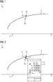
- FIG 1 is an exemplary XY trend diagram 1 with a pressure p along an X axis and with a flow rate q along a Y axis for checking an optimal operating point A1, A2, A3 of the 2-tuple pressure / flow rate of a mixer with a template characteristic curve 2 according to the state of the art.
- FIG. 1 A historical course of the operating point A1, A2, A3 is shown in FIG FIG 1 is visualized by arrows between the three shown operating points A1, A2, A3.
- the operating point A1, A2, A2 can be shifted graphically within the XY trend diagram 1 by an operator of the technical system.
- profound procedural know-how is required.
- "other screws" have to be turned - eg on various valves, motors for the pressure etc.
- the invention is based on the object of specifying a control system for a technical installation which simplifies and makes the optimization of an operating point of the technical installation by an operator of the technical installation more efficient.
- the previously formulated object is achieved by a control system of a technical installation with the features of claim 1.
- the control system has at least one operator station server and one operator station client, the operator station server having a visualization service for outputting image information to the operator station client.
- At least two object models of the technical objects of the technical installation on which the object models are based are stored in the operator station server.
- the operator station server is designed to generate an XY trend diagram with an operating point visualized in the XY trend diagram from a first measured value belonging to the first technical object and a second measured value belonging to the second technical object.
- the operator station server is designed to transfer the XY trend diagram with the operating point to the operator station client using the visualization service.
- the control system according to the invention is characterized in that the operating point is a reference to at least one of the has at least two object models, the operating point being able to be influenced by the technical object on which the referenced object model is based.
- control system is characterized in that the at least one referenced object model is visually presented to an operator of the operator station client when the operating point is selected in the XY trend diagram by means of the visualization service.
- innovated XY trend diagrams are expanded by referenced object models of underlying technical objects, the object models being able to be called up interactively by the operator during the optimization of the operating point during a runtime of the technical system.
- This expansion can have taken place, for example, when the technical installation was planned (so-called "engineering").
- the technical system can be a system from the process industry such as a chemical, pharmaceutical, petrochemical or a system from the food and beverage industry. This also includes all systems from the production industry, plants in which, for example, cars or goods of all kinds are produced.
- Technical systems which are suitable for carrying out the method according to the invention can also come from the field of energy generation. Wind turbines, solar systems or power plants for energy generation are also included in the term technical system.
- control system each have a control system or at least one computer-aided module for controlling and regulating the ongoing process or production.
- a control system is understood to be a computer-aided technical system that includes functionalities for displaying, operating and managing a technical system such as a manufacturing or production plant.
- the control system includes sensors for determining measured values as well as various actuators.
- the control system includes so-called process-related components that are used to control the actuators or sensors.
- the control system has, among other things, means for visualizing the process plant and for engineering.
- control system also includes further processing units for more complex regulations and systems for data storage and processing.
- an "operator station server” is understood to mean a server that centrally records data from an operator control and monitoring system and, as a rule, alarm and measured value archives of a control system of a technical installation and makes them available to users (so-called operators).
- the operator station server usually establishes a communication link to the automation systems of the technical system and forwards data from the technical system to the so-called operator station client, which is used to operate and monitor the operation of the individual functional elements of the technical system.
- the operator station server can have client functions to access the data (archives, messages, tags, variables) of other operator station servers. This means that images of an operation in the technical system are on the operator station server with variables other operator station servers (server-server communication) can be combined.
- the operator station server can, without being limited to this, be a SIMATIC PCS 7 industrial workstation server from SIEMENS.
- An operator is understood to be a human operator of the technical system.
- the operator interacts with the technical system or its control system by means of special user interfaces and controls special technical functions of the technical system.
- the operator can use an operating and monitoring system (the operator station client in connection with the operator station server) of the control system.
- a technical object is understood to be a self-contained technical unit that can be integrated into a higher-level control level.
- a technical object can be, for example, an amalgamation of several measuring points or a larger part of an industrial plant.
- the technical object does not have to come from the field of industrial plants, but can also be, for example, an engine module of an automobile, a ship or the like.
- a computer-implemented representation of the at least two technical objects, the so-called object models is stored in the operator station server. Via these object models, measured values of the technical objects on which the object models are based can be called up and further processed. It can happen that several object models are referenced in the XY trend diagram, since they all have an influence on the operating point and cause a similar (or the same) technical effect.
- the operator of the operator station client undertakes a graphic shift of the operating point in an X or Y direction within the XY trend diagram
- the operator of the operator station client is preferred to use only that object model as a basis lying technical object visually presented, which causes a shift of the working point in the specific X or Y direction.
- the object model (or models) that causes a shift of the operating point within the XY trend diagram in one of the two specific directions is presented visually to the operator.
- FIG 2 shows essentially the same XY trend graph as FIG 1 .
- a reference to an object model 3 is stored in the XY trend diagram 1, which is visually presented to an operator of a technical installation who operates and observes the XY trend diagram.
- the last selected working point A3 is slightly below the optimal working point, which is indicated by an arrow 4 in FIG 2 is shown. If the operator now selects this optimal working point, for example by clicking with a mouse cursor on this point of the XY trend diagram 1, the object model 3 referenced and logically correlated in the XY trend diagram 1 is visually displayed to the operator in the form of a so-called faceplate presented.
- the object model 3 is the one whose underlying technical object must be manipulated in order to move the operating point to the desired position in the direction of the selected position within the XY trend diagram 1.
- it is the faceplate of a technical object designed as a valve controller, by means of which a pressure value 5 can be set accordingly.
- FIG 3 shows how the new working point A4 could be brought into an optimal range by modifying the appropriate object model 3.
- FIG 4 a part of a control system 6 according to the invention of a process plant is shown.
- the control system 6 comprises a server of an operating system or an operator station server 7 and an associated operator station client 8.
- the operator station server 7 and the operator station client 8 are connected to one another via a terminal bus 9 and to other components of the control system 7, not shown connected to an engineering system server or a process data archive.
- a user or operator has access to the operator station server 7 by means of the operator station client 8 by means of the terminal bus 9 in the context of operating and monitoring.
- the terminal bus 9 can, without being limited to it, be designed, for example, as industrial Ethernet.
- the operator station server 7 has a device interface 10 which is connected to a system bus 11.
- the operator system server 7 can use this to communicate with an automation device 12 of the control system 6.
- the plant bus 11 can, without being limited thereto, be designed, for example, as an industrial Ethernet.
- the automation device 12 can in turn be connected to any number of subsystems (not shown).
- a visualization service 13 is integrated in the operator station server 7, via which (visualization) data can be transmitted to the operator station client 8.
- the operator station server 7 has a process image 14 of the process system.
- Plant images that have the innovated XY trend diagrams 1 are visualized on the operator station client 8 by means of the visualization service 14. If the operator would now like to optimize the working point A1, A2, A3, A4 in a certain direction within the XY trend diagram 1, a trend service 15 of the operator station server 7 evaluates the corresponding object models 3 logically referenced in the XY trend diagram 1 and does so Visually display the faceplate of the relevant object model 3 in the operator station client 8 for the operating point optimization.
Landscapes
- Engineering & Computer Science (AREA)
- Physics & Mathematics (AREA)
- General Physics & Mathematics (AREA)
- General Engineering & Computer Science (AREA)
- Theoretical Computer Science (AREA)
- Human Computer Interaction (AREA)
- Automation & Control Theory (AREA)
- Manufacturing & Machinery (AREA)
- Testing And Monitoring For Control Systems (AREA)
- User Interface Of Digital Computer (AREA)
Abstract
Description
- Die Erfindung betrifft ein Leitsystem einer technischen Anlage, welches wenigstens einen Operator Station Server und einen Operator Station Client aufweist, mit den Merkmalen des Anspruchs 1.
- Ein Ziel bei der Automatisierung verfahrenstechnischer Anlagen ist es, diese in ihren optimalen Arbeitspunkten zu betreiben. Zur Überprüfung der jeweiligen Arbeitspunkte haben sich so genannte XY-Trends bzw. XY-Trenddiagramme etabliert. Bei diesen XY-Trend-diagrammen werden zwei (verfahrenstechnische) Prozessmesswerte als 2-Tupel mit gleicher Zeitbasis zusammen mit einer Vorlagenkennlinie visualisiert. Bei den zwei Prozessmesswerten kann es sich beispielsweise um den Druck und die Temperatur einer Turbine handeln. Darüber hinaus kann auch der historische Verlauf der 2-Tupel dargestellt werden, um einen Trend des 2-Tupel Arbeitspunktes verfolgen zu können.
- In
FIG 1 ist ein beispielhaftes XY-Trenddiagramm 1 mit einem Druck p entlang einer X-Achse und mit einem Durchfluss q entlang einer Y-Achse zur Überprüfung eines optimalen Arbeitspunktes A1, A2, A3 des 2-Tupels Druck/Durchfluss eines Mixers mit einer Vorlagenkennlinie 2 nach dem Stand der Technik dargestellt. - Dargestellt ist in FIG ein historischer Verlauf des Arbeitspunktes A1, A2, A3, was in
FIG 1 durch Pfeile zwischen den drei dargestellten Arbeitspunkten A1, A2, A3 visualisiert ist. Der Arbeitspunkt A1, A2, A2 kann von einem Bediener (Operator) der technischen Anlage grafisch innerhalb des XY-Trenddiagramms 1 verschoben werden. Um den Arbeitspunkt A1, A2, A3 manuell verstellen zu können, ist nach dem Stand der Technik jedoch ein tiefgreifendes verfahrenstechnisches Knowhow vonnöten. Um die verschiedenen Prozessgrößen zur Einstellung des Arbeitspunktes A1, A2, A3 beeinflussen zu können, muss an "anderen Schrauben" gedreht werden - z.B. an diversen Ventilen, Motoren für den Druck etc. Gerade bei der Optimierung von Reglern und der Kontrolle beim manuellen Fahren verfahrenstechnischer Anlagenteile zur Einstellung des optimalen Arbeitspunktes A1, A2, A3 ist es dabei wichtig, die Zusammenhänge zwischen den 2-Tupel Prozessmesswerten, den beeinflussenden Messstellen und sonstigen Metadaten der 2-Tupel Prozessmesswerte zu kennen, um die Arbeitspunkte A1, A2, A3 effizient und fehlerfrei in einen optimalen Arbeitsbereich legen zu können. - Der Erfindung liegt die Aufgabe zugrunde, ein Leitsystem für eine technische Anlage anzugeben, welches eine Optimierung eines Arbeitspunktes der technischen Anlage durch einen Operator der technischen Anlage vereinfacht und effizienter gestaltet.
- Die zuvor formulierte Aufgabe wird durch ein Leitsystem einer technischen Anlage mit den Merkmalen des Anspruchs 1 gelöst. Das Leitsystem weist wenigstens einen Operator Station Server und einen Operator Station Client auf, wobei der Operator Station Server einen Visualisierungsdienst zur Ausgabe von Bildinformationen an den Operator Station Client aufweist. In dem Operator Station Server sind wenigstens zwei Objektmodelle von den Objektmodellen jeweils zugrunde liegenden technischen Objekten der technischen Anlage hinterlegt. Der Operator Station Server ist dazu ausgebildet, aus einem ersten, zu dem ersten technischen Objekt gehörigen Messwert und einem zweiten, zu dem zweiten technischen Objekt gehörigen Messwert ein XY-Trenddiagramm mit einem in dem XY-Trenddiagramm visualisierten Arbeitspunkt zu erzeugen. Zudem ist der Operator Station Server dazu ausgebildet, das XY-Trenddiagramm mit dem Arbeitspunkt mittels des Visualisierungsdienstes an den Operator Station Client zu übertragen.
- Das erfindungsgemäße Leitsystem ist dadurch gekennzeichnet, dass der Arbeitspunkt eine Referenz auf wenigstens eines der wenigstens zwei Objektmodelle aufweist, wobei der Arbeitspunkt durch das dem referenzierten Objektmodell zugrunde liegende technische Objekt beeinflussbar ist.
- Zudem ist das erfindungsgemäße Leitsystem dadurch gekennzeichnet, dass einem Bediener (Operator) des Operator Station Clients bei einer Anwahl des Arbeitspunkts in dem XY-Trenddiagramm mittels des Visualisierungsdienstes das wenigstens eine referenzierte Objektmodell visuell dargeboten wird.
- Erfindungsgemäß sind innovierte XY-Trenddiagramme um referenzierte Objektmodelle von zugrunde liegenden technischen Objekten erweitert, wobei die Objektmodelle zu einer Laufzeit der technischen Anlage durch den Operatoren interaktiv bei der Optimierung des Arbeitspunkts abgerufen werden können. Diese Erweiterung kann beispielsweise bei einer Projektierung der technischen Anlage (dem sogenannten "Engineering") erfolgt sein.
- Der Operator weiß bei dem Einsatz des erfindungsgemäßen Leitsystems (ohne tiefergehende Kenntnisse der technischen Anlage haben zu müssen) unmittelbar, welche technischen Objekte im Zusammenhang mit einer Optimierung (Verschiebung) des Arbeitspunktes in dem XY-Trenddiagramm liegen, so dass er gezielt an diesen "Stellrädern" drehen kann. Ein Betrieb der technischen Anlage ist damit deutlich effizienter als bislang bekannt.
- Bei der technischen Anlage kann es sich um eine Anlage aus der Prozessindustrie wie beispielsweise eine chemische, pharmazeutische, petrochemische oder eine Anlage aus der Nahrungs- und Genussmittelindustrie handeln. Hiermit umfasst sind auch jegliche Anlagen aus der Produktionsindustrie, Werke, in denen z.B. Autos oder Güter aller Art produziert werden. Technische Anlagen, die zur Durchführung des erfindungsgemäßen Verfahrens geeignet sind, können auch aus dem Bereich der Energieerzeugung kommen. Windräder, Solaranlagen oder Kraftwerke zur Energieerzeugung sind ebenso von dem Begriff der technischen Anlage umfasst.
- Diese Anlagen verfügen jeweils über ein Leitsystem oder zumindest ein computerunterstütztes Modul zur Steuerung und Regelung des ablaufenden Prozesses oder der Produktion. Unter einem Leitsystem wird im vorliegenden Kontext ein computergestütztes technisches System verstanden, das Funktionalitäten zum Darstellen, Bedienen und Leiten eines technischen Systems wie einer Fertigungs- oder Produktionsanlage umfasst. Das Leitsystem umfasst im vorliegenden Fall Sensoren zur Ermittlung von Messwerten sowie verschiedene Aktoren. Zudem umfasst das Leitsystem sogenannte prozessnahe Komponenten, die zur Ansteuerung der Aktoren bzw. Sensoren dienen. Darüber hinaus weist das Leitsystem u.a. Mittel zur Visualisierung der Prozessanlage und zu einem Engineering auf. Unter dem Begriff Leitsystem sind zusätzlich auch weitere Recheneinheiten für komplexere Regelungen und Systeme zur Datenspeicherung und -verarbeitung zu fassen.
- Unter einem "Operator Station Server" wird vorliegend ein Server verstanden, der zentral Daten eines Bedien- und Beobachtungssystems sowie in der Regel Alarm- und Messwertarchive eines Leitsystems einer technischen Anlage erfasst und Benutzern (sogenannten Operatoren) zur Verfügung stellt. Der Operator Station Server stellt in der Regel eine Kommunikationsverbindung zu Automatisierungssystemen der technischen Anlage her und gibt Daten der technischen Anlage an den sogenannten Operator Station Client weiter, die zur Bedienung und Beobachtung eines Betriebs der einzelnen Funktionselemente der technischen Anlage dienen.
- Der Operator Station Server kann über Client-Funktionen verfügen, um auf die Daten (Archive, Meldungen, Tags, Variablen) anderer Operator Station Server zuzugreifen. Dadurch sind Bilder eines Betriebs der technischen Anlage auf dem Operator Station Server mit Variablen anderer Operator Station Server (Server-Server-Kommunikation) kombinierbar. Bei dem Operator Station Server kann es sich, ohne sich darauf zu beschränken, um einen SIMATIC PCS 7 Industrial Workstation Server der Firma SIEMENS handeln.
- Unter einem Operator wird ein menschlicher Bediener der technischen Anlage verstanden. Der Operator interagiert mittels spezieller Benutzerschnittstellen mit der technischen Anlage bzw. dessen Leitsystem und steuert spezielle technische Funktionen der technischen Anlage. Hierzu kann der Operator ein Bedien- und Beobachtungssystem (den Operator Station Client in Verbindung mit dem Operator Station Server) des Leitsystems nutzen.
- Unter einem technischen Objekt wird eine abgeschlossene technische Einheit verstanden, die in eine übergeordnete Steuerungsebene integrierbar ist. Ein solches technisches Objekt kann zum Beispiel ein Zusammenschluss mehrerer Messstellen oder ein größerer Anlagenteil einer industriellen Anlage sein. Das technische Objekt muss aber nicht dem Feld der Industrieanlagen entstammen, sondern kann beispielsweise auch ein Motormodul eines Automobils, eines Schiffs oder dergleichen sein. In dem Operator Station Server ist eine computerimplementierte Repräsentation der wenigstens zwei technischen Objekte hinterlegt, die sogenannten Objektmodelle. Über diese Objektmodelle können Messwerte der den Objektmodellen jeweils zugrunde liegenden technischen Objekte abgerufen und weiterverarbeitet werden. Es kann vorkommen, dass mehrere Objektmodelle in dem XY-Trenddiagramm referenziert sind, da sie alle einen Einfluss auf den Arbeitspunkt haben und einen ähnlichen (oder den gleichen) technischen Effekt bewirken.
- Bevorzugt wird dem Operator des Operator Station Clients für den Fall, dass er eine grafische Verschiebung des Arbeitspunkts in einer X- oder Y-Richtung innerhalb des XY-Trenddiagramms vornimmt, nur dasjenige Objektmodell eines zugrunde liegenden technischen Objekts visuell dargeboten, das eine Verschiebung des Arbeitspunkts in der spezifischen X- oder Y-Richtung bewirkt. Bei dieser spezifischeren Ausprägung des Leitsystems wird nur das (oder die) Objektmodell dem Operator visuell dargeboten, welches eine Verschiebung des Arbeitspunktes innerhalb des XY-Trenddiagramms in einer der beiden spezifischen Richtungen bewirkt.
- Die oben beschriebenen Eigenschaften, Merkmale und Vorteile dieser Erfindung sowie die Art und Weise, wie diese erreicht werden, werden klarer und deutlicher verständlich im Zusammenhang mit der folgenden Beschreibung des Ausführungsbeispiels, das im Zusammenhang mit den Zeichnungen näher erläutert wird.
- Es zeigen:
- FIG 1
- ein XY-Trenddiagramm gemäß dem Stand der Technik;
- FIG 2
- ein XY-Trenddiagramm mit einem ersten Aspekt;
- FIG 3
- ein XY-Trenddiagramm mit einem zweiten Aspekt; und
- FIG 4
- eine schematische Zeichnung eines Teils eines erfindungsgemäßen Leitsystems.
-
FIG 2 zeigt im Wesentlichen dasselbe XY-Trenddiagramm wieFIG 1 . Zusätzlich ist in dem XY-Trenddiagramm 1 eine Referenz auf ein Objektmodell 3 hinterlegt, das einem Operator einer technischen Anlage, welcher das XY-Trenddiagramm bedient und beobachtet, visuell dargeboten wird. Der zuletzt gewählte Arbeitspunkt A3 liegt etwas unterhalb des optimalen Arbeitspunktes, welcher mit einem Pfeil 4 inFIG 2 angezeigt wird. Wählt der Operator nun diesen optimalen Arbeitspunkt, beispielsweise durch ein Klicken mit einem Mauscursor auf diese Stelle des XY-Trenddiagramms 1, so wird dem Operator das in dem XY-Trenddiagramm 1 referenzierte und logisch korrelierte Objektmodell 3 visuell in Form eines sogenannten Faceplates dargeboten. Dabei handelt es sich bei dem Objektmodell 3 um dasjenige, dessen zugrunde liegendes technisches Objekt manipuliert werden muss, um den Arbeitspunkt zur gewünschten Position in Richtung der gewählten Position innerhalb des XY-Trenddiagramms 1 zu bewegen. Im vorliegenden Beispiel handelt es sich um das Faceplate eines als Ventilregler ausgebildeten technischen Objekts, mittels welchem ein Druckwert 5 entsprechend eingestellt werden kann. - In
FIG 3 ist dargestellt, wie der neue Arbeitspunkt A4 durch die Modifizierung des passenden Objektmodells 3 in einen optimalen Bereich gebracht werden konnte. - In
FIG 4 ist ein Teil eines erfindungsgemäßen Leitsystems 6 einer Prozessanlage dargestellt. Das Leitsystem 6 umfasst einen Server eines Bediensystems bzw. einen Operator Station Server 7 und einen dazugehörigen Operator Station Client 8. Der Operator Station Server 7 und der Operator Station Client 8 sind über einen Terminalbus 9 miteinander und mit nicht dargestellten weiteren Komponenten des Leitsystems 7 wie einem Engineering System Server oder einem Prozessdatenarchiv verbunden. - Ein Benutzer bzw. Operator hat mittels des Operator Station Clients 8 mittels des Terminalbus 9 im Kontext eines Bedienens und Beobachtens Zugriff auf den Operator Station Server 7. Der Terminalbus 9 kann, ohne sich darauf zu beschränken, beispielsweise als Industrial Ethernet ausgebildet sein.
- Der Operator Station Server 7 weist eine Geräteschnittstelle 10 auf, die mit einem Anlagenbus 11 verbunden ist. Hierüber kann der Operator System Server 7 mit einem Automatisierungsgerät 12 des Leitsystems 6 kommunizieren. Der Anlagenbus 11 kann, ohne sich darauf zu beschränken, beispielsweise als Industrial Ethernet ausgebildet sein. Das Automatisierungsgerät 12 kann wiederum mit einer beliebigen Anzahl an Subsystemen (nicht dargestellt) verbunden sein.
- In dem Operator Station Server 7 ist ein Visualisierungsdienst 13 integriert, über den eine Übertragung von (Visualisierungs-)Daten an den Operator Station Client 8 erfolgen kann. Zudem weist der Operator Station Server 7 ein Prozessabbild (Process Image) 14 der Prozessanlage auf.
- Anlagenbilder, die die innovierten XY-Trenddiagramme 1 aufweisen, werden mittels des Visualisierungsdienstes 14 auf dem Operator Station Client 8 visualisiert. Möchte nun der Operator den Arbeitspunkt A1, A2, A3, A4 in eine bestimmte Richtung innerhalb des XY-Trenddiagramms 1 optimieren, wertet ein Trenddienst 15 des Operator Station Servers 7 die entsprechenden logisch in dem XY-Trenddiagramm 1 referenzierten Objektmodelle 3 aus und lässt das Faceplate des betreffenden Objektmodells 3 im Operator Station Client 8 visualisierten Anlagenbild für die Arbeitspunktoptimierung visuell darstellen.
- Obwohl die Erfindung im Detail durch das bevorzugte Ausführungsbeispiel und die Figuren näher illustriert und beschrieben wurde, so ist die Erfindung nicht durch die offenbarten Beispiele eingeschränkt und andere Variationen können vom Fachmann hieraus abgeleitet werden, ohne den Schutzumfang der Erfindung zu verlassen.
Claims (2)
- Leitsystem (6) einer technischen Anlage, welches wenigstens einen Operator Station Server (7) und einen Operator Station Client (8) aufweist,
welcher Operator Station Server (7) einen Visualisierungsdienst (13) zur Ausgabe von Bildinformationen an den Operator Station Client (8) aufweist,
und in welchem Operator Station Server (7) wenigstens zwei Objektmodelle (3) von den Objektmodellen (3) zugrunde liegenden technischen Objekten der technischen Anlage hinterlegt ist,
und wobei der Operator Station Server (7) dazu ausgebildet ist, aus einem ersten, zu dem ersten technischen Objekt gehörigen Messwert und einem zweiten, zu dem zweiten technischen Objekt gehörigen Messwert ein XY-Trenddiagramm (1) mit einem in dem XY-Trenddiagramm (1) visualisierten Arbeitspunkt (A1, A2, A3, A4) zu erzeugen,
und dazu ausgebildet ist, das XY-Trenddiagramm (1) mit dem Arbeitspunkt (A1, A2, A3, A4) mittels des Visualisierungsdienstes (13) an den Operator Station Client (8) zu übertragen,
dadurch gekennzeichnet, dass
das XY-Trenddiagramm (1) und/oder der Arbeitspunkt (A1, A2, A3, A4) eine Referenz auf wenigstens eines der Objektmodelle (3) aufweist, wobei der Arbeitspunkt (A1, A2, A3, A4) durch das dem referenzierten Objektmodell (3) zugrunde liegende technische Objekt beeinflussbar ist,
und dass einem Operator des Operator Station Clients (8) bei einer Anwahl des Arbeitspunkts (A1, A2, A3, A4) in dem XY-Trenddiagramm (1) mittels des Visualisierungsdienstes (13) das wenigstens eine referenzierte Objektmodell (3) visuell dargeboten wird. - Leitsystem gemäß Anspruch 1, bei dem dem Operator des Operator Station Clients (8) für den Fall, dass er eine grafische Verschiebung des Arbeitspunkts (A1, A2, A3, A4) in einer X- oder Y-Richtung innerhalb des XY-Trenddiagramms (1) vornimmt, nur dasjenige Objektmodell (3) eines zugrunde liegenden technischen Objekts visuell dargeboten wird, das eine Verschiebung des Arbeitspunkts (A1, A2, A3, A4) in der spezifischen X- oder Y-Richtung bewirkt.
Priority Applications (3)
| Application Number | Priority Date | Filing Date | Title |
|---|---|---|---|
| EP19202506.2A EP3805882B1 (de) | 2019-10-10 | 2019-10-10 | Leitsystem für eine technische anlage mit trendkurvendiagramm |
| US17/065,624 US11360650B2 (en) | 2019-10-10 | 2020-10-08 | Control system for a technical installation with trend curve diagram |
| CN202011073059.5A CN112650080A (zh) | 2019-10-10 | 2020-10-09 | 具有趋势曲线图的技术设施的控制系统 |
Applications Claiming Priority (1)
| Application Number | Priority Date | Filing Date | Title |
|---|---|---|---|
| EP19202506.2A EP3805882B1 (de) | 2019-10-10 | 2019-10-10 | Leitsystem für eine technische anlage mit trendkurvendiagramm |
Publications (2)
| Publication Number | Publication Date |
|---|---|
| EP3805882A1 true EP3805882A1 (de) | 2021-04-14 |
| EP3805882B1 EP3805882B1 (de) | 2022-06-08 |
Family
ID=68295942
Family Applications (1)
| Application Number | Title | Priority Date | Filing Date |
|---|---|---|---|
| EP19202506.2A Not-in-force EP3805882B1 (de) | 2019-10-10 | 2019-10-10 | Leitsystem für eine technische anlage mit trendkurvendiagramm |
Country Status (3)
| Country | Link |
|---|---|
| US (1) | US11360650B2 (de) |
| EP (1) | EP3805882B1 (de) |
| CN (1) | CN112650080A (de) |
Cited By (2)
| Publication number | Priority date | Publication date | Assignee | Title |
|---|---|---|---|---|
| EP4092502A1 (de) | 2021-05-19 | 2022-11-23 | Siemens Aktiengesellschaft | Leitsystem für eine technische anlage mit trendkurvendiagramm |
| EP4509936A1 (de) * | 2023-08-15 | 2025-02-19 | Siemens Aktiengesellschaft | Leitsystem für eine technische anlage und betriebsverfahren |
Families Citing this family (2)
| Publication number | Priority date | Publication date | Assignee | Title |
|---|---|---|---|---|
| EP4099114B1 (de) * | 2021-05-31 | 2023-07-19 | Siemens Aktiengesellschaft | Verfahren zum erkennen einer eingeschränkten bedienung und beobachtung einer technischen anlage, bedien- und beobachtungssystem und prozessleitsystem |
| EP4394534A1 (de) | 2022-12-29 | 2024-07-03 | Siemens Aktiengesellschaft | Verfahren zur überwachung von mess- und/oder zustandsgrössen in einem prozessautomatisierungssystem und prozessleitsystem |
Citations (4)
| Publication number | Priority date | Publication date | Assignee | Title |
|---|---|---|---|---|
| EP2458464A1 (de) * | 2010-11-30 | 2012-05-30 | Siemens Aktiengesellschaft | Verfahren zum Visualisieren und Bedienen eines zu steuernden technischen Prozesses |
| US20140081430A1 (en) * | 2011-05-20 | 2014-03-20 | Susanne Timsjo | System, Method, Work Station And Computer Program Product For Controlling An Industrial Process |
| DE102018124303A1 (de) * | 2017-10-02 | 2019-04-04 | Fisher-Rosemount Systems, Inc. | Bedieneranzeige mit Vorschauumschaltung |
| EP3528074A1 (de) * | 2018-02-16 | 2019-08-21 | Siemens Aktiengesellschaft | Verfahren zum überprüfen der beziehung zwischen einem visuell auf einem operator-client eines prozessleitsystems dargestellten und einem akustisch ausgegebenen prozessalarm eines prozessobjektes sowie operator-system |
Family Cites Families (56)
| Publication number | Priority date | Publication date | Assignee | Title |
|---|---|---|---|---|
| JPS5962947A (ja) * | 1982-10-01 | 1984-04-10 | Fanuc Ltd | 数値制御方式 |
| DE3930581A1 (de) * | 1989-09-13 | 1991-03-21 | Asea Brown Boveri | Arbeitsplatz fuer prozessfuehrungspersonal |
| EP0511941A1 (de) | 1991-04-30 | 1992-11-04 | Maschinenfabrik Rieter Ag | Vorrichtung zur Steuerung einer Spinnereianlage oder eine Spinnereimaschine |
| US5546521A (en) * | 1991-10-15 | 1996-08-13 | International Business Machines Corporation | Dynamic presentation of contextual help and status information |
| JP3082169B2 (ja) | 1991-11-20 | 2000-08-28 | インターナショナル・ビジネス・マシーンズ・コーポレ−ション | データ処理システム及びその実行方法 |
| JPH0825216B2 (ja) * | 1991-12-11 | 1996-03-13 | 日精樹脂工業株式会社 | 成形条件設定方法 |
| EP0588108A3 (en) * | 1992-08-24 | 1996-07-31 | Gildemeister Ag | Arrangement to operate a computer controlled manufacturing system |
| JPH06314181A (ja) * | 1993-04-28 | 1994-11-08 | Hitachi Ltd | 複数ディスプレイによる対話型制御システムとその制御方法 |
| US5907820A (en) * | 1996-03-22 | 1999-05-25 | Applied Materials, Inc. | System for acquiring and analyzing a two-dimensional array of data |
| JP3211663B2 (ja) * | 1996-05-20 | 2001-09-25 | 株式会社日立製作所 | プラント運転情報表示方法及びプラント運転監視装置 |
| TW434774B (en) * | 1998-09-28 | 2001-05-16 | Promos Technologies Inc | Measuring method of swing curve |
| WO2001067191A2 (de) * | 2000-03-06 | 2001-09-13 | Siemens Aktiengesellschaft | Vorrichtung und verfahren zur bedienung, beobachtung und/oder überwachung einer fertigungsvorrichtung |
| JP2002087703A (ja) * | 2000-09-12 | 2002-03-27 | Murata Mach Ltd | 繊維機械の機台情報表示システム |
| JP3602482B2 (ja) * | 2001-08-07 | 2004-12-15 | 三菱電機株式会社 | 監視制御装置 |
| JP2004164150A (ja) * | 2002-11-12 | 2004-06-10 | Yokogawa Electric Corp | プラント運転支援装置 |
| US7864158B1 (en) * | 2004-10-06 | 2011-01-04 | Mcgeever Daniel Robert | Use of graphical information to control processes |
| US20060217822A1 (en) * | 2005-03-28 | 2006-09-28 | Karthikeya Ramanathan | Presenting status information of field devices in process control plants |
| KR20070013682A (ko) * | 2005-07-27 | 2007-01-31 | (주)마빈시스템 | 복수 구동기의 운전제어를 위한 교번제어기와 이를 이용한복수 구동기의 운전제어시스템 |
| US7720552B1 (en) | 2006-06-05 | 2010-05-18 | Rockwell Automation Technologies, Inc. | Virtual knob lever arm as analog control element |
| EP1950639B1 (de) | 2007-01-23 | 2013-05-29 | Siemens Aktiengesellschaft | Verfahren zum Betreiben einer Prozessanlage, Prozessanlage und Computerprogrammprodukt |
| JP2008229322A (ja) * | 2007-02-22 | 2008-10-02 | Morita Mfg Co Ltd | 画像処理方法、画像表示方法、画像処理プログラム、記憶媒体、画像処理装置、x線撮影装置 |
| DE102007039167A1 (de) * | 2007-08-20 | 2009-01-22 | Siemens Ag | Umrichter-Bedienfeld |
| JP2009116718A (ja) * | 2007-11-08 | 2009-05-28 | Hitachi Ltd | プラント監視制御システム |
| JP5077826B2 (ja) * | 2008-03-10 | 2012-11-21 | 横河電機株式会社 | プラント情報表示装置およびプラント情報表示方法 |
| EP2124114A1 (de) * | 2008-05-23 | 2009-11-25 | Siemens Aktiengesellschaft | Verfahren zur Auswahl von auf einem Operator-System dargestellten Objekten |
| JP4561890B2 (ja) * | 2008-07-01 | 2010-10-13 | ダイキン工業株式会社 | 群管理装置および群管理システム |
| EP2419880B1 (de) * | 2009-04-13 | 2019-09-25 | Koninklijke Philips N.V. | Plausible referenzkurven für dynamische kontrastverstärkte bildgebungsstudien |
| DE102009021062A1 (de) | 2009-05-13 | 2010-11-18 | Abb Technology Ag | Alarmverwaltungssystem |
| US8683317B2 (en) * | 2009-09-23 | 2014-03-25 | Fisher-Rosemount Systems, Inc. | Dynamically linked graphical messages for process control systems |
| EP2431827A1 (de) * | 2010-09-19 | 2012-03-21 | ABB Research Ltd. | Identifizierungsbezogene Datenelemente |
| US8559750B2 (en) * | 2010-11-08 | 2013-10-15 | Lg Innotek Co., Ltd. | Method of performing adaptive contrast enhancement using hyperbolic tangent curve and image histogram |
| US9581994B2 (en) * | 2011-04-05 | 2017-02-28 | Fisher-Rosemount Systems, Inc. | Methods and apparatus to manage process control resources |
| ITRM20110482A1 (it) * | 2011-09-14 | 2013-03-15 | Prb S R L | Cruscotto per la visualizzazione delle criticità inerenti i parametri in un controllo di processi. |
| JP5522149B2 (ja) * | 2011-11-09 | 2014-06-18 | 横河電機株式会社 | 運転監視画面表示装置および運転監視画面表示方法 |
| US20130246037A1 (en) * | 2012-03-15 | 2013-09-19 | Kenneth Paul Ceglia | Methods and apparatus for monitoring operation of a system asset |
| US20140098105A1 (en) * | 2012-10-10 | 2014-04-10 | Chevron U.S.A. Inc. | Systems and methods for improved graphical display of real-time data in a user interface |
| JP2014167765A (ja) * | 2013-02-28 | 2014-09-11 | Seung-Chul Lee | セクターグラフ基盤設備の運営状態監視装置及びその方法 |
| US9081651B2 (en) * | 2013-03-13 | 2015-07-14 | Ford Global Technologies, Llc | Route navigation with optimal speed profile |
| US10803636B2 (en) * | 2013-03-15 | 2020-10-13 | Fisher-Rosemount Systems, Inc. | Graphical process variable trend monitoring, predictive analytics and fault detection in a process control system |
| EP2999999A4 (de) * | 2013-05-23 | 2017-03-29 | Duke Manufacturing Co. | Lebensmittelherstellungsvorrichtung und -verfahren |
| CN103439884B (zh) * | 2013-07-19 | 2015-12-23 | 大连理工大学 | 一种基于模糊滑模的智能汽车横向控制方法 |
| JP2015176370A (ja) * | 2014-03-14 | 2015-10-05 | オムロン株式会社 | 制御システム、方法、プログラムおよび情報処理装置 |
| EP2921921A1 (de) * | 2014-03-18 | 2015-09-23 | Siemens Aktiengesellschaft | Verfahren zum Betrieb einer Bedienungseinrichtung eines Automatisierungsgeräts |
| CN104200075B (zh) * | 2014-08-20 | 2017-11-10 | 浙江中控软件技术有限公司 | 应用于工业监控系统中的趋势图的绘制方法和装置 |
| KR20160041561A (ko) * | 2014-10-08 | 2016-04-18 | 엘지전자 주식회사 | 공기조화장치용 컨트롤러 |
| GB2535597B (en) * | 2014-12-17 | 2021-11-24 | Fisher Rosemount Systems Inc | Methods and apparatus to provide a role-based user interface |
| JP6240117B2 (ja) * | 2015-04-03 | 2017-11-29 | ファナック株式会社 | 文字の表示幅の自動変更機能を有する数値制御装置 |
| DE102015211299A1 (de) * | 2015-06-19 | 2016-12-22 | Robert Bosch Gmbh | Werkzeugsystem mit einer Anzeige in grafischer Form für eine Montageanlage und ein Verfahren für ein Werkzeugsystem einer Montageanlage |
| CN105274277B (zh) * | 2015-11-25 | 2017-07-11 | 中冶南方工程技术有限公司 | 一种转炉干法除尘抑爆的吹氧控制方法 |
| CN107273103A (zh) * | 2016-04-07 | 2017-10-20 | 佛山市顺德区美的电热电器制造有限公司 | 一种智能家电的烹饪曲线显示方法和装置 |
| EP3252555A1 (de) * | 2016-05-31 | 2017-12-06 | Siemens Aktiengesellschaft | Vorrichtung zur rechnergestützten visualisierung von prozesszuständen |
| US20180129191A1 (en) * | 2016-11-04 | 2018-05-10 | Rockwell Automation Technologies, Inc. | Industrial automation system machine analytics for a connected enterprise |
| DE102017108546A1 (de) * | 2017-04-21 | 2018-10-25 | Sig Technology Ag | Produktionsparameterverlaufsansicht als Teil einer Benutzeroberfläche zum Überwachen und/oder Steuern einer Verpackungsanlage |
| DE102017108547A1 (de) * | 2017-04-21 | 2018-10-25 | Sig Technology Ag | Bereitstellen einer Benutzeroberfläche zum Überwachen und/oder Steuern einer Verpackungsanlage |
| US11243677B2 (en) * | 2017-10-02 | 2022-02-08 | Fisher-Rosemount Systems, Inc. | Systems and methods for ease of graphical display configuration design in a process control plant |
| EP3495903B1 (de) * | 2017-12-05 | 2020-02-26 | Siemens Aktiengesellschaft | Verfahren zum bedienen und beobachten einer zu steuernden technischen anlage sowie operator-system |
-
2019
- 2019-10-10 EP EP19202506.2A patent/EP3805882B1/de not_active Not-in-force
-
2020
- 2020-10-08 US US17/065,624 patent/US11360650B2/en active Active
- 2020-10-09 CN CN202011073059.5A patent/CN112650080A/zh active Pending
Patent Citations (4)
| Publication number | Priority date | Publication date | Assignee | Title |
|---|---|---|---|---|
| EP2458464A1 (de) * | 2010-11-30 | 2012-05-30 | Siemens Aktiengesellschaft | Verfahren zum Visualisieren und Bedienen eines zu steuernden technischen Prozesses |
| US20140081430A1 (en) * | 2011-05-20 | 2014-03-20 | Susanne Timsjo | System, Method, Work Station And Computer Program Product For Controlling An Industrial Process |
| DE102018124303A1 (de) * | 2017-10-02 | 2019-04-04 | Fisher-Rosemount Systems, Inc. | Bedieneranzeige mit Vorschauumschaltung |
| EP3528074A1 (de) * | 2018-02-16 | 2019-08-21 | Siemens Aktiengesellschaft | Verfahren zum überprüfen der beziehung zwischen einem visuell auf einem operator-client eines prozessleitsystems dargestellten und einem akustisch ausgegebenen prozessalarm eines prozessobjektes sowie operator-system |
Cited By (3)
| Publication number | Priority date | Publication date | Assignee | Title |
|---|---|---|---|---|
| EP4092502A1 (de) | 2021-05-19 | 2022-11-23 | Siemens Aktiengesellschaft | Leitsystem für eine technische anlage mit trendkurvendiagramm |
| WO2022243362A1 (de) | 2021-05-19 | 2022-11-24 | Siemens Aktiengesellschaft | Leitsystem für eine technische anlage mit trendkurvendiagramm |
| EP4509936A1 (de) * | 2023-08-15 | 2025-02-19 | Siemens Aktiengesellschaft | Leitsystem für eine technische anlage und betriebsverfahren |
Also Published As
| Publication number | Publication date |
|---|---|
| CN112650080A (zh) | 2021-04-13 |
| US20210109504A1 (en) | 2021-04-15 |
| EP3805882B1 (de) | 2022-06-08 |
| US11360650B2 (en) | 2022-06-14 |
Similar Documents
| Publication | Publication Date | Title |
|---|---|---|
| EP3876046B1 (de) | Rückannotation von operatorselektionen | |
| EP3805882B1 (de) | Leitsystem für eine technische anlage mit trendkurvendiagramm | |
| EP3279756B1 (de) | Diagnoseeinrichtung und verfahren zur überwachung des betriebs einer technischen anlage | |
| EP3953774B1 (de) | Vorrichtung zum auffinden von alarmursachen | |
| WO2001067196A1 (de) | Betriebsnetzwerksystem | |
| EP3538962B1 (de) | Verfahren zur analyse von fehlfunktionen in einer anlage der prozessautomatisierung | |
| DE102007029321B4 (de) | Verfahren zum Betreiben eines Feldgerätes in einem benutzerfreundlichen Modus | |
| WO2021094482A1 (de) | Leitsystem für eine technische anlage mit visuell codiertem trendkurvendiagramm | |
| EP3680740A1 (de) | Anzeige von objekten als folge der selektion einer alarmmeldung | |
| EP4370986B1 (de) | Leitsystem für eine technische anlage mit verkleinerten ansichten von anlagenbildern | |
| EP4295203A1 (de) | Leitsystem für eine technische anlage mit trendkurvendiagramm | |
| WO2022238496A1 (de) | Leitsystem für eine technische anlage | |
| EP3361341A1 (de) | Verfahren zur überwachung der zustände von geräten eines automatisierungssystems sowie operator-system | |
| DE102004003052A1 (de) | Anlageinformationssystem und Verfahren für dasselbe | |
| EP3819727B1 (de) | Leitsystem für eine technische anlage mit trendkurvendiagramm | |
| EP4332699B1 (de) | Operator-unterstützendes leitsystem für eine technische anlage und betriebsverfahren | |
| EP4290326A1 (de) | Leitsystem für eine technische anlage und betriebsverfahren | |
| EP4341759B1 (de) | Alarmassoziierte container in anlagenbildern technischer anlagen | |
| WO2025176445A1 (de) | Anzeige kritischer trendkurven bei der bedienung und beobachtung | |
| EP4124917A1 (de) | Steuerbare verbindung zwischen datenquellen und datensenken bei einer automatisierungslösung | |
| EP4030252B1 (de) | Lastmanagement bei der darstellung einer alarmmeldungsanzeige | |
| EP4509936A1 (de) | Leitsystem für eine technische anlage und betriebsverfahren | |
| EP4592782A1 (de) | Zentralisation der bedienung und beobachtung | |
| EP4280003A1 (de) | Leitsystem für eine technische anlage | |
| EP3701341B1 (de) | Verfahren zur rechnergestützten verarbeitung von betriebsdaten eines technischen systems |
Legal Events
| Date | Code | Title | Description |
|---|---|---|---|
| PUAI | Public reference made under article 153(3) epc to a published international application that has entered the european phase |
Free format text: ORIGINAL CODE: 0009012 |
|
| STAA | Information on the status of an ep patent application or granted ep patent |
Free format text: STATUS: THE APPLICATION HAS BEEN PUBLISHED |
|
| AK | Designated contracting states |
Kind code of ref document: A1 Designated state(s): AL AT BE BG CH CY CZ DE DK EE ES FI FR GB GR HR HU IE IS IT LI LT LU LV MC MK MT NL NO PL PT RO RS SE SI SK SM TR |
|
| AX | Request for extension of the european patent |
Extension state: BA ME |
|
| STAA | Information on the status of an ep patent application or granted ep patent |
Free format text: STATUS: REQUEST FOR EXAMINATION WAS MADE |
|
| 17P | Request for examination filed |
Effective date: 20211005 |
|
| RBV | Designated contracting states (corrected) |
Designated state(s): AL AT BE BG CH CY CZ DE DK EE ES FI FR GB GR HR HU IE IS IT LI LT LU LV MC MK MT NL NO PL PT RO RS SE SI SK SM TR |
|
| GRAP | Despatch of communication of intention to grant a patent |
Free format text: ORIGINAL CODE: EPIDOSNIGR1 |
|
| STAA | Information on the status of an ep patent application or granted ep patent |
Free format text: STATUS: GRANT OF PATENT IS INTENDED |
|
| INTG | Intention to grant announced |
Effective date: 20220322 |
|
| GRAS | Grant fee paid |
Free format text: ORIGINAL CODE: EPIDOSNIGR3 |
|
| GRAA | (expected) grant |
Free format text: ORIGINAL CODE: 0009210 |
|
| STAA | Information on the status of an ep patent application or granted ep patent |
Free format text: STATUS: THE PATENT HAS BEEN GRANTED |
|
| AK | Designated contracting states |
Kind code of ref document: B1 Designated state(s): AL AT BE BG CH CY CZ DE DK EE ES FI FR GB GR HR HU IE IS IT LI LT LU LV MC MK MT NL NO PL PT RO RS SE SI SK SM TR |
|
| REG | Reference to a national code |
Ref country code: AT Ref legal event code: REF Ref document number: 1497353 Country of ref document: AT Kind code of ref document: T Effective date: 20220615 Ref country code: CH Ref legal event code: EP |
|
| REG | Reference to a national code |
Ref country code: DE Ref legal event code: R096 Ref document number: 502019004560 Country of ref document: DE |
|
| REG | Reference to a national code |
Ref country code: IE Ref legal event code: FG4D Free format text: LANGUAGE OF EP DOCUMENT: GERMAN |
|
| REG | Reference to a national code |
Ref country code: LT Ref legal event code: MG9D |
|
| REG | Reference to a national code |
Ref country code: NL Ref legal event code: MP Effective date: 20220608 |
|
| PG25 | Lapsed in a contracting state [announced via postgrant information from national office to epo] |
Ref country code: SE Free format text: LAPSE BECAUSE OF FAILURE TO SUBMIT A TRANSLATION OF THE DESCRIPTION OR TO PAY THE FEE WITHIN THE PRESCRIBED TIME-LIMIT Effective date: 20220608 Ref country code: NO Free format text: LAPSE BECAUSE OF FAILURE TO SUBMIT A TRANSLATION OF THE DESCRIPTION OR TO PAY THE FEE WITHIN THE PRESCRIBED TIME-LIMIT Effective date: 20220908 Ref country code: LT Free format text: LAPSE BECAUSE OF FAILURE TO SUBMIT A TRANSLATION OF THE DESCRIPTION OR TO PAY THE FEE WITHIN THE PRESCRIBED TIME-LIMIT Effective date: 20220608 Ref country code: HR Free format text: LAPSE BECAUSE OF FAILURE TO SUBMIT A TRANSLATION OF THE DESCRIPTION OR TO PAY THE FEE WITHIN THE PRESCRIBED TIME-LIMIT Effective date: 20220608 Ref country code: GR Free format text: LAPSE BECAUSE OF FAILURE TO SUBMIT A TRANSLATION OF THE DESCRIPTION OR TO PAY THE FEE WITHIN THE PRESCRIBED TIME-LIMIT Effective date: 20220909 Ref country code: FI Free format text: LAPSE BECAUSE OF FAILURE TO SUBMIT A TRANSLATION OF THE DESCRIPTION OR TO PAY THE FEE WITHIN THE PRESCRIBED TIME-LIMIT Effective date: 20220608 Ref country code: BG Free format text: LAPSE BECAUSE OF FAILURE TO SUBMIT A TRANSLATION OF THE DESCRIPTION OR TO PAY THE FEE WITHIN THE PRESCRIBED TIME-LIMIT Effective date: 20220908 |
|
| PG25 | Lapsed in a contracting state [announced via postgrant information from national office to epo] |
Ref country code: RS Free format text: LAPSE BECAUSE OF FAILURE TO SUBMIT A TRANSLATION OF THE DESCRIPTION OR TO PAY THE FEE WITHIN THE PRESCRIBED TIME-LIMIT Effective date: 20220608 Ref country code: LV Free format text: LAPSE BECAUSE OF FAILURE TO SUBMIT A TRANSLATION OF THE DESCRIPTION OR TO PAY THE FEE WITHIN THE PRESCRIBED TIME-LIMIT Effective date: 20220608 |
|
| PG25 | Lapsed in a contracting state [announced via postgrant information from national office to epo] |
Ref country code: NL Free format text: LAPSE BECAUSE OF FAILURE TO SUBMIT A TRANSLATION OF THE DESCRIPTION OR TO PAY THE FEE WITHIN THE PRESCRIBED TIME-LIMIT Effective date: 20220608 |
|
| PG25 | Lapsed in a contracting state [announced via postgrant information from national office to epo] |
Ref country code: SM Free format text: LAPSE BECAUSE OF FAILURE TO SUBMIT A TRANSLATION OF THE DESCRIPTION OR TO PAY THE FEE WITHIN THE PRESCRIBED TIME-LIMIT Effective date: 20220608 Ref country code: SK Free format text: LAPSE BECAUSE OF FAILURE TO SUBMIT A TRANSLATION OF THE DESCRIPTION OR TO PAY THE FEE WITHIN THE PRESCRIBED TIME-LIMIT Effective date: 20220608 Ref country code: RO Free format text: LAPSE BECAUSE OF FAILURE TO SUBMIT A TRANSLATION OF THE DESCRIPTION OR TO PAY THE FEE WITHIN THE PRESCRIBED TIME-LIMIT Effective date: 20220608 Ref country code: PT Free format text: LAPSE BECAUSE OF FAILURE TO SUBMIT A TRANSLATION OF THE DESCRIPTION OR TO PAY THE FEE WITHIN THE PRESCRIBED TIME-LIMIT Effective date: 20221010 Ref country code: ES Free format text: LAPSE BECAUSE OF FAILURE TO SUBMIT A TRANSLATION OF THE DESCRIPTION OR TO PAY THE FEE WITHIN THE PRESCRIBED TIME-LIMIT Effective date: 20220608 Ref country code: EE Free format text: LAPSE BECAUSE OF FAILURE TO SUBMIT A TRANSLATION OF THE DESCRIPTION OR TO PAY THE FEE WITHIN THE PRESCRIBED TIME-LIMIT Effective date: 20220608 Ref country code: CZ Free format text: LAPSE BECAUSE OF FAILURE TO SUBMIT A TRANSLATION OF THE DESCRIPTION OR TO PAY THE FEE WITHIN THE PRESCRIBED TIME-LIMIT Effective date: 20220608 |
|
| PG25 | Lapsed in a contracting state [announced via postgrant information from national office to epo] |
Ref country code: PL Free format text: LAPSE BECAUSE OF FAILURE TO SUBMIT A TRANSLATION OF THE DESCRIPTION OR TO PAY THE FEE WITHIN THE PRESCRIBED TIME-LIMIT Effective date: 20220608 Ref country code: IS Free format text: LAPSE BECAUSE OF FAILURE TO SUBMIT A TRANSLATION OF THE DESCRIPTION OR TO PAY THE FEE WITHIN THE PRESCRIBED TIME-LIMIT Effective date: 20221008 |
|
| REG | Reference to a national code |
Ref country code: DE Ref legal event code: R097 Ref document number: 502019004560 Country of ref document: DE |
|
| PG25 | Lapsed in a contracting state [announced via postgrant information from national office to epo] |
Ref country code: AL Free format text: LAPSE BECAUSE OF FAILURE TO SUBMIT A TRANSLATION OF THE DESCRIPTION OR TO PAY THE FEE WITHIN THE PRESCRIBED TIME-LIMIT Effective date: 20220608 |
|
| PLBE | No opposition filed within time limit |
Free format text: ORIGINAL CODE: 0009261 |
|
| STAA | Information on the status of an ep patent application or granted ep patent |
Free format text: STATUS: NO OPPOSITION FILED WITHIN TIME LIMIT |
|
| PG25 | Lapsed in a contracting state [announced via postgrant information from national office to epo] |
Ref country code: DK Free format text: LAPSE BECAUSE OF FAILURE TO SUBMIT A TRANSLATION OF THE DESCRIPTION OR TO PAY THE FEE WITHIN THE PRESCRIBED TIME-LIMIT Effective date: 20220608 |
|
| 26N | No opposition filed |
Effective date: 20230310 |
|
| PG25 | Lapsed in a contracting state [announced via postgrant information from national office to epo] |
Ref country code: SI Free format text: LAPSE BECAUSE OF FAILURE TO SUBMIT A TRANSLATION OF THE DESCRIPTION OR TO PAY THE FEE WITHIN THE PRESCRIBED TIME-LIMIT Effective date: 20220608 Ref country code: MC Free format text: LAPSE BECAUSE OF FAILURE TO SUBMIT A TRANSLATION OF THE DESCRIPTION OR TO PAY THE FEE WITHIN THE PRESCRIBED TIME-LIMIT Effective date: 20220608 |
|
| REG | Reference to a national code |
Ref country code: CH Ref legal event code: PL |
|
| REG | Reference to a national code |
Ref country code: BE Ref legal event code: MM Effective date: 20221031 |
|
| PG25 | Lapsed in a contracting state [announced via postgrant information from national office to epo] |
Ref country code: LU Free format text: LAPSE BECAUSE OF NON-PAYMENT OF DUE FEES Effective date: 20221010 |
|
| PG25 | Lapsed in a contracting state [announced via postgrant information from national office to epo] |
Ref country code: LI Free format text: LAPSE BECAUSE OF NON-PAYMENT OF DUE FEES Effective date: 20221031 Ref country code: CH Free format text: LAPSE BECAUSE OF NON-PAYMENT OF DUE FEES Effective date: 20221031 |
|
| PG25 | Lapsed in a contracting state [announced via postgrant information from national office to epo] |
Ref country code: BE Free format text: LAPSE BECAUSE OF NON-PAYMENT OF DUE FEES Effective date: 20221031 |
|
| PG25 | Lapsed in a contracting state [announced via postgrant information from national office to epo] |
Ref country code: IE Free format text: LAPSE BECAUSE OF NON-PAYMENT OF DUE FEES Effective date: 20221010 |
|
| PGFP | Annual fee paid to national office [announced via postgrant information from national office to epo] |
Ref country code: GB Payment date: 20231106 Year of fee payment: 5 |
|
| PGFP | Annual fee paid to national office [announced via postgrant information from national office to epo] |
Ref country code: IT Payment date: 20231025 Year of fee payment: 5 Ref country code: FR Payment date: 20231017 Year of fee payment: 5 Ref country code: DE Payment date: 20231214 Year of fee payment: 5 |
|
| PG25 | Lapsed in a contracting state [announced via postgrant information from national office to epo] |
Ref country code: CY Free format text: LAPSE BECAUSE OF FAILURE TO SUBMIT A TRANSLATION OF THE DESCRIPTION OR TO PAY THE FEE WITHIN THE PRESCRIBED TIME-LIMIT Effective date: 20220608 |
|
| PG25 | Lapsed in a contracting state [announced via postgrant information from national office to epo] |
Ref country code: MK Free format text: LAPSE BECAUSE OF FAILURE TO SUBMIT A TRANSLATION OF THE DESCRIPTION OR TO PAY THE FEE WITHIN THE PRESCRIBED TIME-LIMIT Effective date: 20220608 Ref country code: HU Free format text: LAPSE BECAUSE OF FAILURE TO SUBMIT A TRANSLATION OF THE DESCRIPTION OR TO PAY THE FEE WITHIN THE PRESCRIBED TIME-LIMIT; INVALID AB INITIO Effective date: 20191010 |
|
| PG25 | Lapsed in a contracting state [announced via postgrant information from national office to epo] |
Ref country code: TR Free format text: LAPSE BECAUSE OF FAILURE TO SUBMIT A TRANSLATION OF THE DESCRIPTION OR TO PAY THE FEE WITHIN THE PRESCRIBED TIME-LIMIT Effective date: 20220608 |
|
| PG25 | Lapsed in a contracting state [announced via postgrant information from national office to epo] |
Ref country code: MT Free format text: LAPSE BECAUSE OF FAILURE TO SUBMIT A TRANSLATION OF THE DESCRIPTION OR TO PAY THE FEE WITHIN THE PRESCRIBED TIME-LIMIT Effective date: 20220608 |
|
| PG25 | Lapsed in a contracting state [announced via postgrant information from national office to epo] |
Ref country code: BG Free format text: LAPSE BECAUSE OF FAILURE TO SUBMIT A TRANSLATION OF THE DESCRIPTION OR TO PAY THE FEE WITHIN THE PRESCRIBED TIME-LIMIT Effective date: 20220608 |
|
| PG25 | Lapsed in a contracting state [announced via postgrant information from national office to epo] |
Ref country code: BG Free format text: LAPSE BECAUSE OF FAILURE TO SUBMIT A TRANSLATION OF THE DESCRIPTION OR TO PAY THE FEE WITHIN THE PRESCRIBED TIME-LIMIT Effective date: 20220608 |
|
| REG | Reference to a national code |
Ref country code: DE Ref legal event code: R119 Ref document number: 502019004560 Country of ref document: DE |
|
| GBPC | Gb: european patent ceased through non-payment of renewal fee |
Effective date: 20241010 |
|
| PG25 | Lapsed in a contracting state [announced via postgrant information from national office to epo] |
Ref country code: DE Free format text: LAPSE BECAUSE OF NON-PAYMENT OF DUE FEES Effective date: 20250501 |
|
| PG25 | Lapsed in a contracting state [announced via postgrant information from national office to epo] |
Ref country code: GB Free format text: LAPSE BECAUSE OF NON-PAYMENT OF DUE FEES Effective date: 20241010 |
|
| PG25 | Lapsed in a contracting state [announced via postgrant information from national office to epo] |
Ref country code: FR Free format text: LAPSE BECAUSE OF NON-PAYMENT OF DUE FEES Effective date: 20241031 |
|
| PG25 | Lapsed in a contracting state [announced via postgrant information from national office to epo] |
Ref country code: IT Free format text: LAPSE BECAUSE OF NON-PAYMENT OF DUE FEES Effective date: 20241010 |
|
| REG | Reference to a national code |
Ref country code: AT Ref legal event code: MM01 Ref document number: 1497353 Country of ref document: AT Kind code of ref document: T Effective date: 20241010 |
|
| PG25 | Lapsed in a contracting state [announced via postgrant information from national office to epo] |
Ref country code: AT Free format text: LAPSE BECAUSE OF NON-PAYMENT OF DUE FEES Effective date: 20241010 |
|
| PGFP | Annual fee paid to national office [announced via postgrant information from national office to epo] |
Ref country code: AT Payment date: 20260410 Year of fee payment: 5 |