EP3809314A1 - Détection d'objets 3d à partir d'un arrière-plan d'images 2d étalonnées - Google Patents
Détection d'objets 3d à partir d'un arrière-plan d'images 2d étalonnées Download PDFInfo
- Publication number
- EP3809314A1 EP3809314A1 EP19306344.3A EP19306344A EP3809314A1 EP 3809314 A1 EP3809314 A1 EP 3809314A1 EP 19306344 A EP19306344 A EP 19306344A EP 3809314 A1 EP3809314 A1 EP 3809314A1
- Authority
- EP
- European Patent Office
- Prior art keywords
- cones
- cluster
- bounding box
- shape
- images
- Prior art date
- Legal status (The legal status is an assumption and is not a legal conclusion. Google has not performed a legal analysis and makes no representation as to the accuracy of the status listed.)
- Withdrawn
Links
Images


Classifications
-
- G—PHYSICS
- G06—COMPUTING OR CALCULATING; COUNTING
- G06V—IMAGE OR VIDEO RECOGNITION OR UNDERSTANDING
- G06V20/00—Scenes; Scene-specific elements
- G06V20/60—Type of objects
- G06V20/64—Three-dimensional [3D] objects
-
- G—PHYSICS
- G06—COMPUTING OR CALCULATING; COUNTING
- G06F—ELECTRIC DIGITAL DATA PROCESSING
- G06F18/00—Pattern recognition
- G06F18/20—Analysing
- G06F18/22—Matching criteria, e.g. proximity measures
-
- G—PHYSICS
- G06—COMPUTING OR CALCULATING; COUNTING
- G06F—ELECTRIC DIGITAL DATA PROCESSING
- G06F18/00—Pattern recognition
- G06F18/20—Analysing
- G06F18/23—Clustering techniques
-
- G—PHYSICS
- G06—COMPUTING OR CALCULATING; COUNTING
- G06T—IMAGE DATA PROCESSING OR GENERATION, IN GENERAL
- G06T7/00—Image analysis
- G06T7/70—Determining position or orientation of objects or cameras
- G06T7/73—Determining position or orientation of objects or cameras using feature-based methods
- G06T7/74—Determining position or orientation of objects or cameras using feature-based methods involving reference images or patches
-
- G—PHYSICS
- G06—COMPUTING OR CALCULATING; COUNTING
- G06V—IMAGE OR VIDEO RECOGNITION OR UNDERSTANDING
- G06V10/00—Arrangements for image or video recognition or understanding
- G06V10/20—Image preprocessing
- G06V10/25—Determination of region of interest [ROI] or a volume of interest [VOI]
-
- G—PHYSICS
- G06—COMPUTING OR CALCULATING; COUNTING
- G06V—IMAGE OR VIDEO RECOGNITION OR UNDERSTANDING
- G06V20/00—Scenes; Scene-specific elements
- G06V20/10—Terrestrial scenes
-
- G—PHYSICS
- G06—COMPUTING OR CALCULATING; COUNTING
- G06T—IMAGE DATA PROCESSING OR GENERATION, IN GENERAL
- G06T2210/00—Indexing scheme for image generation or computer graphics
- G06T2210/12—Bounding box
Definitions
- the present disclosure relates generally to object detection and more specifically to techniques for three-dimensional (3D) object detection.
- 3D object detection In recent years, a number of effective techniques have been developed to detect objects in two-dimensional (2D) space (referred to as “2D object detection”).
- 2D object detection One effective technique is a convolutional neural network, which may accurately detect objects in 2D space from a 2D image of the scene.
- 3D object detection there is a growing desire to detect objects in 3D space (referred to as “3D object detection”).
- 3D object detection is still an open problem, and is not practical in many cases.
- 3D object detection is often simply not accurate, with the size, shape or location of the detected object differing considerably from that of the actual object.
- Second, 3D object detection may require specific data sources that may not always be available, or if available, may not be fully accurate.
- 3D object detection techniques require a 3D model (e.g., a 3D mesh) be reconstructed, for example, using structure-from-motion (SfM) photogrammetry, and then operate upon the 3D model.
- a 3D model e.g., a 3D mesh
- SfM structure-from-motion
- 3D object detection may consume in inordinant amount of hardware resources (e.g., processing and memory resources). Such resource consumption may burden computing devices, leading to slow response time and delays, and even preclude 3D object detection from being performed on some type of computing device (e.g., low-power mobile devices).
- techniques are provided for 3D object detection by detecting objects in 2D (as 2D bounding boxes) in a set of calibrated 2D images of a scene, matching the 2D bounding boxes that correspond to the same object, and reconstructing objects in 3D (represented as 3D bounding boxes) from the corresponding matched 2D bounding boxes.
- the techniques may leverage the advances in 2D object detection to address the unresolved issue of 3D object detection. If sparse 3D points for the scene are available (e.g., as a byproduct of SfM photogrammetry reconstruction) they may be used to refine the 3D bounding boxes (e.g., to reduce their size).
- such techniques may improve accuracy, may be less dependent on the availability of specific data sources, and may decrease resource utilization to improve the operation of computing devices utilized in the task.
- the term "scene” refers to a portion of the physical environment which may include one or more objects.
- a scene may be captured in a set of one or more images (e.g., 2D images) produced by one or more cameras.
- the term "calibrated" when used in the context of an image refers to the image having known acquisition parameters (i.e. camera parameters), such as positon, orientation focal length, etc.
- Fig. 1A is a diagram 100 illustrating an example camera cone 120, bounded by planes 122-128 extending from the position of the camera, by a near plane 130 and a far plane 140.
- the camera cone 120 may capture an object 150.
- Fig. 1B is diagram 110 illustrating an example object cone 160 for an object 150 that is a sub-region of a camera cone 120.
- Fig. 2 is a block diagram of an example electronic device (e.g., a computing device) that may be used with the present techniques.
- the electronic device includes a central processing unit (CPU) 210 that may be coupled to a chipset 220 by a front side bus 215.
- the chipset 220 includes a memory controller hub 225 that is responsible for communications with high-speed devices such as system memory 230 and a graphics subsystem (e.g., a graphics card) 240.
- the memory controller hub 225 is coupled to the system memory 230 which is adapted to store a wide range of software and data being actively used by the CPU 210 by a high-speed memory bus 235.
- the memory controller hub 225 is coupled to a graphics subsystem 240 (e.g., a graphics card) by a high-speed graphics bus 245.
- the graphics subsystem 240 includes a GPU 250 and graphics memory 255, among other components.
- the graphics subsystem 240 is coupled to at least one display screen 260.
- the chipset 220 further includes an input/output controller hub 265 coupled to the memory controller hub by an internal bus 267.
- the input/output controller hub 265 may support a variety of types of peripheral buses for connecting to other system components.
- the system components may include one or more I/O devices 270, one or more persistent storage devices 275, one or more network interfaces 280, among other system components.
- the network interface(s) 280 may allow communication with other electronic devices over a computer network to enable various types of collaborative, distributed, or remote computing.
- the components of the electronic device 200 may execute a number of different types of software that utilize various sources of data (e.g., files) persistently stored in storage devices 275 and loaded into memory 130 when needed.
- software of 3D reality modeling software 190 such the ContextCaptureTM 3D reality modeling software available from Bentley Systems, Incorporated, may be loaded into memory and executed by the components of the electronic device.
- the 3D reality modeling software 290 may include a number of software processes, including a user interface (UI) process 291, a 2D object detection process 292 and a 3D object detection process 294, a SfM photogrammetry process 296, among other software processes.
- UI user interface
- 2D object detection process 292 and a 3D object detection process 294
- SfM photogrammetry process 296 among other software processes.
- the 2D object detection process 292 and the 3D object detection process 294 may operate to detect objects in 2D (as 2D bounding boxes) in a set of calibrated 2D images of a scene, match the 2D bounding boxes that correspond to the same object, and reconstruct objects in 3D (represented as 3D bounding boxes) from the corresponding, matched 2D bounding boxes. If information from SfM photogrammetry reconstruction is available from the SfM photogrammetry process 296, it may be used to refine the 3D bounding boxes.
- the software processes may 291-296 may utilize a number of types of data maintained in memory 230 and/or on a storage devices 275.
- This data may include the set of calibrated 2D images 298 of the scene, supplied from one or more cameras (not shown) and, in some cases, sparse 3D point 299 obtained (e.g., as a byproduct) of reconstruction by the SfM photogrammetry process 296 on the set of 2D images 298, among other data.
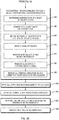
- Figs. 3A and 3B are flow diagram of an example sequence of step 300 for 3D object detection by detecting objects in 2D (as 2D bounding boxes) in a set of calibrated 2D images, matching the 2D bounding boxes that correspond to the same objects, and reconstructing objects in 3D (as 3D bounding boxes) from the corresponding, matched 2D bounding boxes.
- the 3D reality modeling software 290 accesses a set calibrated 2D images 298 of a scene captured by one or more cameras (i.e., whose parameters such as positon, orientation focal length, etc. are known).
- the 2D object detection process 292 detects objects in 2D in the set of 2D images as 2D bounding boxes.
- the 2D object detection process 292 may use any of a variety of automated 2D detection techniques, for example, a convolutional neural network, deep machine learning, or manual user definition via input received via an I/O device 270 and interpreted by the UI process 291. It is expected that most of the 2D bounding boxes will correctly bound objects, but it is possible that there are false negatives (i.e.
- an object is not detected and there is not a 2D bounding box at its location in the 2D image
- false positives an detection occurs absent an object and there is a 2D bounding box at a location in the 2D image where there is no actual object
- partial detections an object is detected but a 2D bounding box only partly covers the object, e.g., because of error in the detection algorithm, or because the object is occluded from the viewpoint of the 2D image. Robustness is desired against these situations.
- the 2D object detection process 292 also labels each 2D bounding box with a label (e.g., class name) that identifies a type of the object (e.g., window, car, motorcycle, book, etc.).
- a label e.g., class name
- a type of the object e.g., window, car, motorcycle, book, etc.
- Figs. 4A-4D are example 2D images 410, 420, 430, 440 of an antenna in which a series of antenna elements have been detected in 2D (as 2D bounding boxes) 410, 420, 430, 440.
- the same antenna element may be detected as a slightly different 2D bounding box in each 2D image.
- a label (not shown) may be associated with each 2D bounding box identifying the type of the object (e.g., antenna element)
- the 3D object detection process 294 matches ones of the 2D bounding boxes that correspond to the same object. This procedure may be conducted via a number of individual operations. At step 315, the 3D object detection process 294 determines an object cone for each 2D bounding box. At step 320, for each object cone, the 3D object detection process 294 determines any other object cones that intersect the object cone. If labels are available, the determination may be limited to other object cones that share the same label.
- FIG. 5 is a diagram illustrating multiple (in this example, 3) intersecting object cones 510, 520, 530 for an object 440.
- the 2D bounding boxes are "perfectly" detected, such that the object falls fully inside the intersection of the corresponding object cones 510, 520, 530. If the 2D bounding boxes were less than perfect, at least a portion of the object may fall outside of one or more of the object cones 510, 520, 530.
- the 3D object detection process 294 builds a cluster of object cones for each object, for example, using a "greedy" clustering algorithm.
- Step 325 may include a number of sub-steps.
- the 3D object detection process 294 selects triplets of intersecting object cones. A triplet may be picked randomly from among sets of three intersecting object cones.
- the 3D object detection process 294 determines a center point P for each triplet.
- the center point P may be a 3D point determined by triangulation from the centers of the constituent object cones.
- the 3D object detection process 294 determining a score for each triplet based on a number of other object cones that contain the center point P.
- a high score indicates that the center point P is also inside a large number of other object cones, and thereby has a high probability of containing a real object.
- the score may be compared to a predetermined threshold and the triplet retained or discard based on the comparison.
- the 3D object detection process 294 determines any other object cones that contain the center point P of the triplet for each retained triplet.
- the 3D object detection process 294 adds the one or more other object cones to each triplet to produce each cluster.
- the 3D object detection process 294 reconstructs a 3D bounding box that represents the object in 3D from the corresponding matched 2D bounding boxes that represent the object in 2D. This procedure may be conducted via a number of individual operations.
- the 3D object detection process 294 determines an intersection of a subset of the object cones of each cluster. The subset may be selected to include those object cones that maximize similarity between a projection of the 3D bounding box onto one or more 2D images of the scene and 2D bounding boxes in the one or more 2D images.
- the 3D object detection process 294 generates a 3D shape for each cluster based on the intersection of the subset of object cones. Using a subset in the generating, rather than a simple intersection of all the object cones, may prevent generating a 3D shape that is overly small.
- multiple 3D shapes may be generated that actually represent the same object (e.g. since the clusters are formed using a "greedy” clustering algorithm).
- the 3D object detection process 294 merges the 3D shape for each cluster with the 3D shape of any other clusters determined to represent the same object.
- the merging may use a "greedy" clustering algorithm similar to the one that may be used to originally form each cluster. In the merging, the 3D shape of each cluster is refined to be generated from the object boxes of all the clusters merged with it.
- the 3D object detection process 294 detects any visibility issues caused by a 3D shape occluding the 3D shape of any other clusters that are determined to represent other 3D objects. Until this step, visibility has not been taken into account. A 3D shape from one cluster may hide the 3D shape from another cluster.
- the 3D object detection process 294 redistributes object cones from a cluster to one or more other clusters and repeats generating the 3D shape.
- Figs. 6A and 6B are diagrams 600, 650 depicting examples of redistributing object cones to address visibility issues.
- object 610 may block object 620 in some 2D images and initially all the object cones may be associated with object 610.
- object cones 630 may stay associated with the 3D shape for object 610, while object cones 640 may be redistributed for use with the 3D shape of object 620.
- object 610 may block object 620 in some 2D images and initially object cones 660, 662 may be associated with object 610.
- object cones 660 may stay associated with the 3D shape for object 610, while object cone 662 may be redistributed for use with the 3D space of object 620, along with existing object cones 670.
- the 3D object detection process 294 compares the number of object cones in each cluster to a threshold and removes any cluster that does not include at least a threshold number of object cones. Then, at step 385, if there are any object cones that do not belong to any cluster after step 380, the 3D object detection process 294 loops, and repeats clustering steps for these object cones.
- the resulting 3D shape for each cluster is used as the 3D bounding box for an object.
- the 3D bounding box may be assigned the same label as the 2D bounding boxes from which it was derived.
- Fig. 7 is an example 2D image 700 of the antenna from Figs. 4A-4C in which objects have been detected in 3D (as 3D bounding boxes) 712, 714, 716, 718.
- the 3D bounding boxes may be assigned a label (e.g., antenna element).
- a reconstructed 3D bounding box determined in steps 355-385 may be overly large. For example, if the 2D images used are all from substantially the same direction, it may be difficult to evaluate the depth of the object and the 3D bounding box may over extend substantially into the foreground or background.
- Fig. 8A is an example 2D image 800 including a 3D bounding box 820 for an object (here, a microwave oven) 810 which is overly large. If available, 3D points from SfM photogrammetry (e.g., as a byproduct) may be used to refine the 3D bounding box.
- the SfM photogrammetry process 296 applies SfM photogrammetry to the set of 2D images 298 of the scene and may determine (e.g., as a byproduct) sparse 3D points that represent objects. Such points may be detected by determining 3D points that fall within the intersection of object cones of a cluster for each object.
- the 3D object detection process 294 computes a SfM-based 3D bounding box that surrounds the 3D points for each object. Then, at optional step 397, the 3D object detection process 294 refines (e.g., reduces the size) of one or more 3D bounding boxes based on a corresponding SfM-based 3D bounding box.
- Such reduction may be to the smallest bounding box between the SfM-based 3D bounding box and the original 3D bounding box where a projection of the based 3D bounding box onto each 2D image is "close” (i.e. within a deviation threshold) of the 2D bounding box for the object.
- Fig. 8B is an example 2D image 850 including a reduced 3D bounding box 830 for the object (here, a microwave oven) 810 from Fig. 8A based on 3D points from SfM photogrammetry. As can be seen, the 3D bounding box 830 better conforms to the actual size of the object.
- each determined 3D bounding box is returned, to be displayed on the display screen 260 by the UI process 290, stored to a storage device 275, or otherwise utilized
Landscapes
- Engineering & Computer Science (AREA)
- Theoretical Computer Science (AREA)
- General Physics & Mathematics (AREA)
- Physics & Mathematics (AREA)
- Multimedia (AREA)
- Data Mining & Analysis (AREA)
- Computer Vision & Pattern Recognition (AREA)
- Life Sciences & Earth Sciences (AREA)
- Bioinformatics & Cheminformatics (AREA)
- Bioinformatics & Computational Biology (AREA)
- Artificial Intelligence (AREA)
- Evolutionary Biology (AREA)
- Evolutionary Computation (AREA)
- General Engineering & Computer Science (AREA)
- Image Analysis (AREA)
Priority Applications (2)
| Application Number | Priority Date | Filing Date | Title |
|---|---|---|---|
| EP19306344.3A EP3809314A1 (fr) | 2019-10-15 | 2019-10-15 | Détection d'objets 3d à partir d'un arrière-plan d'images 2d étalonnées |
| US16/726,412 US11281935B2 (en) | 2019-10-15 | 2019-12-24 | 3D object detection from calibrated 2D images |
Applications Claiming Priority (1)
| Application Number | Priority Date | Filing Date | Title |
|---|---|---|---|
| EP19306344.3A EP3809314A1 (fr) | 2019-10-15 | 2019-10-15 | Détection d'objets 3d à partir d'un arrière-plan d'images 2d étalonnées |
Publications (1)
| Publication Number | Publication Date |
|---|---|
| EP3809314A1 true EP3809314A1 (fr) | 2021-04-21 |
Family
ID=68581670
Family Applications (1)
| Application Number | Title | Priority Date | Filing Date |
|---|---|---|---|
| EP19306344.3A Withdrawn EP3809314A1 (fr) | 2019-10-15 | 2019-10-15 | Détection d'objets 3d à partir d'un arrière-plan d'images 2d étalonnées |
Country Status (2)
| Country | Link |
|---|---|
| US (1) | US11281935B2 (fr) |
| EP (1) | EP3809314A1 (fr) |
Families Citing this family (4)
| Publication number | Priority date | Publication date | Assignee | Title |
|---|---|---|---|---|
| US12033315B1 (en) * | 2021-03-09 | 2024-07-09 | Bentley Systems, Incorporated | Machine vision-based techniques for non-contact structural health monitoring |
| CN113436273A (zh) * | 2021-06-28 | 2021-09-24 | 南京冲浪智行科技有限公司 | 一种3d场景定标方法、定标装置及其定标应用 |
| KR20230060300A (ko) | 2021-10-27 | 2023-05-04 | 현대자동차주식회사 | 3차원 객체 검출 장치 및 방법 |
| KR20230143383A (ko) * | 2022-04-05 | 2023-10-12 | 현대자동차주식회사 | 3차원 객체 검출 장치 및 방법 |
Citations (1)
| Publication number | Priority date | Publication date | Assignee | Title |
|---|---|---|---|---|
| WO2014190081A1 (fr) * | 2013-05-21 | 2014-11-27 | Transocean Sedco Forex Ventures Limited | Utilisation de la vision par ordinateur pour éviter des collisions au cours d'opérations de forage |
Family Cites Families (10)
| Publication number | Priority date | Publication date | Assignee | Title |
|---|---|---|---|---|
| US7099510B2 (en) | 2000-11-29 | 2006-08-29 | Hewlett-Packard Development Company, L.P. | Method and system for object detection in digital images |
| GB2389293B (en) * | 2000-12-06 | 2004-10-13 | Sun Microsystems Inc | Using ancillary geometry for visibility determination |
| GB0114157D0 (en) * | 2001-06-11 | 2001-08-01 | Canon Kk | 3D Computer modelling apparatus |
| GB0326374D0 (en) | 2003-11-12 | 2003-12-17 | British Telecomm | Object detection in images |
| SE528068C2 (sv) | 2004-08-19 | 2006-08-22 | Jan Erik Solem Med Jsolutions | Igenkänning av 3D föremål |
| US8406470B2 (en) | 2011-04-19 | 2013-03-26 | Mitsubishi Electric Research Laboratories, Inc. | Object detection in depth images |
| US9367922B2 (en) * | 2014-03-06 | 2016-06-14 | Nec Corporation | High accuracy monocular moving object localization |
| US9619691B2 (en) | 2014-03-07 | 2017-04-11 | University Of Southern California | Multi-view 3D object recognition from a point cloud and change detection |
| CN106462940A (zh) | 2014-10-09 | 2017-02-22 | 微软技术许可有限责任公司 | 图像中通用对象检测 |
| US9934563B2 (en) | 2015-10-29 | 2018-04-03 | Empire Technology Development Llc | 3D object rotation-based mechanical parts selection through 2D image processing |
-
2019
- 2019-10-15 EP EP19306344.3A patent/EP3809314A1/fr not_active Withdrawn
- 2019-12-24 US US16/726,412 patent/US11281935B2/en active Active
Patent Citations (1)
| Publication number | Priority date | Publication date | Assignee | Title |
|---|---|---|---|---|
| WO2014190081A1 (fr) * | 2013-05-21 | 2014-11-27 | Transocean Sedco Forex Ventures Limited | Utilisation de la vision par ordinateur pour éviter des collisions au cours d'opérations de forage |
Non-Patent Citations (1)
| Title |
|---|
| CAO PEI ET AL: "Multi-View Frustum Pointnet for Object Detection in Autonomous Driving", 2019 IEEE INTERNATIONAL CONFERENCE ON IMAGE PROCESSING (ICIP), IEEE, 22 September 2019 (2019-09-22), pages 3896 - 3899, XP033647528, DOI: 10.1109/ICIP.2019.8803572 * |
Also Published As
| Publication number | Publication date |
|---|---|
| US11281935B2 (en) | 2022-03-22 |
| US20210110202A1 (en) | 2021-04-15 |
Similar Documents
| Publication | Publication Date | Title |
|---|---|---|
| US11842438B2 (en) | Method and terminal device for determining occluded area of virtual object | |
| EP3803803B1 (fr) | Estimation d'éclairage | |
| US10373380B2 (en) | 3-dimensional scene analysis for augmented reality operations | |
| CN111582054B (zh) | 点云数据处理方法及装置、障碍物检测方法及装置 | |
| CN108229322B (zh) | 基于视频的人脸识别方法、装置、电子设备及存储介质 | |
| US11281935B2 (en) | 3D object detection from calibrated 2D images | |
| US10776973B2 (en) | Vanishing point computation for single vanishing point images | |
| WO2018089163A1 (fr) | Procédés et systèmes de réalisation d'estimation de pose d'objet | |
| US20180075611A1 (en) | Model-based three-dimensional head pose estimation | |
| CN114359377B (zh) | 一种实时6d位姿估计方法及计算机可读存储介质 | |
| US12112533B2 (en) | Method and apparatus for data calculation in neural network model, and image processing method and apparatus | |
| CN115330940A (zh) | 一种三维重建方法、装置、设备和介质 | |
| JP2020536332A (ja) | キーフレームスケジューリング方法及び装置、電子機器、プログラム並びに媒体 | |
| CN114612544A (zh) | 图像处理方法、装置、设备和存储介质 | |
| CN116342899A (zh) | 一种目标检测定位方法、装置、设备及存储介质 | |
| CN114792355A (zh) | 虚拟形象生成方法、装置、电子设备和存储介质 | |
| CN114708374A (zh) | 虚拟形象生成方法、装置、电子设备和存储介质 | |
| CN113592994B (zh) | 用于纹理贴图的方法、装置和存储介质 | |
| CN112991451B (zh) | 图像识别方法、相关装置及计算机程序产品 | |
| CN114565872A (zh) | 视频数据处理方法、装置、设备及计算机可读存储介质 | |
| CN113888635A (zh) | 视觉定位方法、相关装置及计算机程序产品 | |
| CN115965735B (zh) | 纹理贴图的生成方法和装置 | |
| CN117290537B (zh) | 图像搜索方法、装置、设备及存储介质 | |
| CN116012883B (zh) | 一种图像生成模型的训练方法、图像生成方法及装置 | |
| CN114820908B (zh) | 虚拟形象生成方法、装置、电子设备和存储介质 |
Legal Events
| Date | Code | Title | Description |
|---|---|---|---|
| PUAI | Public reference made under article 153(3) epc to a published international application that has entered the european phase |
Free format text: ORIGINAL CODE: 0009012 |
|
| STAA | Information on the status of an ep patent application or granted ep patent |
Free format text: STATUS: THE APPLICATION HAS BEEN PUBLISHED |
|
| AK | Designated contracting states |
Kind code of ref document: A1 Designated state(s): AL AT BE BG CH CY CZ DE DK EE ES FI FR GB GR HR HU IE IS IT LI LT LU LV MC MK MT NL NO PL PT RO RS SE SI SK SM TR |
|
| AX | Request for extension of the european patent |
Extension state: BA ME |
|
| STAA | Information on the status of an ep patent application or granted ep patent |
Free format text: STATUS: THE APPLICATION IS DEEMED TO BE WITHDRAWN |
|
| 18D | Application deemed to be withdrawn |
Effective date: 20211022 |