EP3812531A1 - Profilsystem zur halterung eines flächenelements - Google Patents
Profilsystem zur halterung eines flächenelements Download PDFInfo
- Publication number
- EP3812531A1 EP3812531A1 EP19204645.6A EP19204645A EP3812531A1 EP 3812531 A1 EP3812531 A1 EP 3812531A1 EP 19204645 A EP19204645 A EP 19204645A EP 3812531 A1 EP3812531 A1 EP 3812531A1
- Authority
- EP
- European Patent Office
- Prior art keywords
- profile
- profile system
- drainage
- balcony
- basic
- Prior art date
- Legal status (The legal status is an assumption and is not a legal conclusion. Google has not performed a legal analysis and makes no representation as to the accuracy of the status listed.)
- Granted
Links
Images


Classifications
-
- E—FIXED CONSTRUCTIONS
- E04—BUILDING
- E04F—FINISHING WORK ON BUILDINGS, e.g. STAIRS, FLOORS
- E04F11/00—Stairways, ramps, or like structures; Balustrades; Handrails
- E04F11/18—Balustrades; Handrails
- E04F11/181—Balustrades
- E04F11/1812—Details of anchoring to the wall or floor
-
- E—FIXED CONSTRUCTIONS
- E04—BUILDING
- E04D—ROOF COVERINGS; SKY-LIGHTS; GUTTERS; ROOF-WORKING TOOLS
- E04D13/00—Special arrangements or devices in connection with roof coverings; Protection against birds; Roof drainage ; Sky-lights
- E04D13/04—Roof drainage; Drainage fittings in flat roofs, balconies or the like
- E04D13/064—Gutters
-
- E—FIXED CONSTRUCTIONS
- E04—BUILDING
- E04F—FINISHING WORK ON BUILDINGS, e.g. STAIRS, FLOORS
- E04F11/00—Stairways, ramps, or like structures; Balustrades; Handrails
- E04F11/18—Balustrades; Handrails
- E04F11/181—Balustrades
- E04F11/1851—Filling panels, e.g. concrete, sheet metal panels
- E04F11/1853—Glass panels
Definitions
- the invention relates to a profile system for holding a surface element for fall protection such as a railing or a railing construction for balconies or terraces.
- All-glass railings As fall protection for balconies, terraces or loggias of buildings are known. These all-glass railings have a transparency without annoying posts or the like. on.
- the all-glass railings can be arranged in support profiles and held clamped. U-profiles in particular are used as support profiles.
- balcony drains, gutters or water spouts Balcony drainage takes place through balcony drains, gutters or water spouts. With all drainage it must be ensured that there is a sufficient gradient for the water to lead away from the building and that the drains, gutters or spouts do not clog. Otherwise there is a risk of backwater, which can lead to various types of damage.
- balcony floor slabs or terrace floors are made of in-situ concrete, for example. which are then equipped with rain gutters and / or balcony railings.
- the EP 2 025 827 A1 discloses a "finishing profile arrangement for balconies, terraces and the like".
- the end profile arrangement for the vertical end faces of balconies or terraces enables covering by an end profile, the end faces being covered by the end profile at least in a horizontal sub-area and the end profile having at least one drainage opening for the removal of any liquid.
- the end profile has an anchoring leg that can be anchored in the balcony below the top of the balcony and a cover leg protruding from the anchoring leg in the direction of the top of the balcony and at least partially covering the respective end face.
- an elongated cover panel is attached to the end profile, creating a gap through which water can pass.
- a solution for arranging a rain gutter on a balcony floor slab or a terrace is known.
- a carrier profile which is arranged on the front side of the balcony and can be used as a closing profile for balconies or terraces is arranged in order to arrange a channel profile on this that is arranged to be relatively displaceable relative to the carrier profile.
- the gutter profile can be attached at different heights to the carrier profile, depending on the desired inclination, so that the rain gutters have the necessary slope even in front of longer balcony fronts or terraces, with the carrier profile always attached at the front parallel to the balcony or terrace floor.
- the DE 10 2017 000 145 A1 discloses a "gutter sewage system for draining surface water on surfaces (balconies, terraces, flat roofs) in the outdoor area". Gutter sewage systems can be implemented with the system.
- An edge beam is designed for the creation of gutter sewage systems.
- the edge support has an L-shaped basic profile, between whose vertical web above and a vertical web below there is a horizontal support surface.
- a fastening device for load-bearing railing posts is known in which profile rods are arranged on the lower chord of the balcony slab, on which the front side rounded holder elements are arranged, which also rest on the balcony slab face, and against each of which a fastening device for a load-bearing railing post can be braced.
- the object of the invention is therefore to provide a support frame made of profiles which, compared to the known support frames, enables simple assembly and a sophisticated facade design.
- a profile system for fall protection such as a railing or a railing construction with a basic profile that has the function of a holding or supporting profile in combination with a drainage device for controlled balcony or terrace drainage is disclosed.
- at least two functionally different components in balcony or terrace construction are combined to form a profile system, so that both the function of a support or holding profile and the function of drainage are fulfilled with a simple installation option.
- the basic or retaining profile itself can be designed in a one-part or multi-part embodiment.
- the one-piece design can have railing posts, for example.
- the profile joints of the basic profile are designed to be stretchable, for example, with EPDM molded parts and a permanently elastic joint.
- the basic profile can be designed with a fall protection in aluminum or steel or as a post guardrail. The inner edge of the basic profile pointing in the direction of a floor no longer has to be veneered or covered in the profile system due to the combined design according to the invention.
- the basic profile is combined with the drainage device with an openly accessible water-carrying channel to form the profile system mentioned.
- the water-carrying channel is made in particular of aluminum, metal or stainless steel or plastic.
- the water runs into the water-bearing channel or drainage channel, so that a defined drainage takes place.
- the water is guided in this channel and not in a hollow chamber.
- Lateral lids or cover parts which are designed, for example, round or rectangular, can be arranged so that good stability is achieved.
- a dirt grille in particular a removable dirt grille, can be arranged on the channel.
- the dirt grille is designed, for example, as an expanded metal grille or as a perforated plate.
- the dirt grille can be inserted or thickened. It can have holes in the form of a perforated plate or slots. The holes can be flush or deeper than the side walls of the channel.
- the dirt grille can be designed so that it can be swiveled out or in. It is made from a thin metal such as the aforementioned perforated plate or from a mesh fabric.
- the fall protection in one embodiment as glass railings, which are held by the basic profile, are in particular made of up to 2 ⁇ 10 mm thick laminated glass with a total thickness of approx. 21.5 mm.
- the glass railings can be precisely adjusted in their alignment in the basic profile.
- the profile system according to the invention with the basic profile and the drainage device has the advantage that it can be designed variably and can be installed very easily with different fastening brackets. This can be done, for example, with adjustable side mounting, adjustable mounting from above or by combining two mounting brackets through multiple adjustable mounting.
- the height of the coverings on the balconies or terraces can be designed to be variable in height and, thanks to the various designs and / or arrangement options of the profile system, can be easily handled with different installation options.
- the lower areas of the profile system that is to say the drainage channel or the building or a substructure, can be veneered without a cover by an adapted embodiment of the glass pane. This takes place in that the surface element or the glass pane is "pulled down", that is to say extends over the end face and thus a separate cover is not required.
- the railing construction can therefore also be attached without posts, for example.
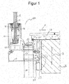
- a profile system 100 with a one-piece first basic profile 1 is shown.
- a surface element 5, in particular a pane of glass 5, is held in a clamping manner in the basic profile 1.
- the surface element 5 can alternatively also made of metal, plastic or the like. be trained.
- a fastening bracket for side mounting 7, which is connected to the base profile 1, is arranged.
- the one-piece first basic profile 1 has a screen in the lateral outward direction 11 and a screen in the lateral inward direction 12. Furthermore, a soffit cover 13 is formed.
- the glass pane 5 held clamped in the first basic profile 1 is held by glazing seals 15 arranged on both sides of the glass pane 5.
- the glass pane 5 can be adjusted in its vertical alignment by adjusting elements 16 for the glazing within the first basic profile 1. This results in an exact fine adjustment of the glass pane 5 by the adjusting elements.
- the glass pane 5 is inserted within a clamping shoe 17 arranged in the bottom area of the first one-piece base profile 1. There is a basic profile drainage 18 away from the bottom area of the first basic profile 1.
- the profile system 100 with the first basic profile 1 and the drainage channel 21 can be hooked into the fastening bracket for side mounting 7.
- a lift-out safeguard 14 prevents the profile system 100 from being unhooked from the fastening bracket for side assembly 7. This enables assembly by hanging the profile system 100 in combination with the further adjustment possibility of the adjustment of the glass pane 5 by the adjusting elements 16 for the glazing, a multiple effect on the arrangement, positioning and adjustment of the glass pane 5 of the balcony railing.
- the entire construction is vertically adjustable in height.
- the mounting bracket for side mounting 7 is designed with a corrugation.
- a first opening 29 is made in the fastening bracket for side mounting 7, the diameter of which is slightly larger than the bore for a first fastening screw 31 to be introduced.
- a first nut 29 is placed, which is also designed to be corrugated at least on its fastening bracket for side assembly 7. After the first fastening screw 31 has been screwed in, there is a certain amount of play in order to move the fastening bracket for the side mounting 7 upwards or downwards in the vertical direction. Thus, the height of the arrangement can be adjusted.
- the advantage of this design is that, if necessary, a subsequent adjustment is possible by loosening the screw connection and shifting it again. There are no adhesions, fillings or the like. carried out for fastening, so that the arrangement remains adjustable to a limited extent.
- a drainage channel 21 is formed below a floor covering 19 of a balcony or terrace.
- a dirt grille 22 is inserted or clipped into the drainage channel 21.
- the dirt grille 22 can be designed to be pivotable in and out.
- the dirt grille 22 can be made of aluminum, stainless steel, plastic or the like. be trained.
- a drain connection 23 is formed which opens into a drain pipe 24.
- the gutter drainage through the discharge nozzle 23 is suitable for standard HT [high temperature] pipes. These HT pipes can be used for sewer pipes. They are heat-resistant up to approx. 95 °, insofar as this is required.
- the direction of the arrow A indicates the direction of flow of the water for drainage.
- Fig. 2 shows a further embodiment of the profile system 100.
- Another fastening bracket for assembly from above 8 is shown.
- a leg of the fastening bracket extending in the horizontal direction is formed for assembly from above 8.
- This leg is also through a Screw connection securely fastened.
- a second bore 32 is made and a second nut 22 is arranged on the leg, which nut is adjustable on the corrugated leg.
- the second fastening screw 34 to be introduced is formed by the formation of the second bore 32, which, like the first bore 31, has an enlarged diameter compared to the bore for the second fastening screw 34 to be introduced, so that the fastening screw 34 has some play when it is introduced and the profile system 100 is thus adjustable in two directions.
- This illustrated construction of the embodiment shown is designed to be displaceable in the horizontal and vertical directions. This is shown by the arrows B and C.
- Fig. 3 shows the profile system 100 with a one-piece first basic profile 1 with a two-part adjustable mounting bracket 9.
- the arrow direction in two directions on the two-part mounting bracket 9 indicates the adjustment in the vertical direction on the screw connection in this position by the arrow direction B and the adjustment in the horizontal direction the direction of the arrow C.
- the thick arrows A on the balcony surface and in the balcony covering 19 show the direction of flow of the water.
- a perforated plate 20 is arranged on the first basic profile 1. Between this perforated plate 20 and the balcony covering 19, the water can flow off in the direction of the drainage channel 21 and can be drained off through the drainage connection 23 through the drainage pipe 24.
- the profile system 100 can be moved in height and width, that is to say horizontally and vertically.
- a dirt grille 22 ' is arranged that differs from the execution of the representations Fig. 1 and Fig. 2 is formed and arranged.
- a thermal insulation composite system 25 is formed.
- Fig. 4 shows a profile system 100 with a two-part second base profile 2 with the mounting bracket for side mounting 7.
- the second part of the second base profile 2 is connected to the first part of the base profile 2, in which the glass pane 5 is clamped, by a screw connection.
- This first part of the second two-part basic profile 2 is designed with a leg pointing outward, away from the building or the balcony covering 19, referred to as "fall protection" made of aluminum 3. It's a soffit visor 13 arranged.
- the glass pane 5 can be finely adjusted within the first part of the two-part second basic profile 2 and additionally adjusted in its vertical position by the spreading of the adjusting element for the glazing 16 by the screw to be inserted.
- Fig. 5 shows a profile system 100 with a two-part second basic profile 2 with an attached fall protection in steel 4.
- a panel inside 12 is formed in an upper, in the direction of the upper edge of the glass pane 5 pointing area of the basic profile 2 around a differently designed leg.
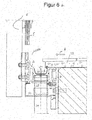
- Figure 6a shows the profile system 100 with the two-part second basic profile 2.
- the second part of the basic profile 2 has a post railing 6 attached.
- the filling profiles are generally perpendicular.
- This embodiment is used in particular for posts or round or square bars and various hollow and solid profiles.
- a post guardrail 6 is thus formed.
- the fastening bracket is designed for side mounting 7. This fastening bracket 7 is secured in its position by the anti-lift device 14.
- the drainage channel 21 is accessible from the outside or from above, that is to say from the top of the balcony covering 19.
- the post railing 6 has a filling, in particular with a glass pane 5.
- Figure 6b shows the profile system 100 with the two-part second basic profile 2 and the attached post railing 6.
- An inner pane of glass is arranged as a surface element 5 and is supported in a linear manner over the height edges.
- the posts of the post railing 6 are freely positioned horizontally in the profile system 100.
- the surface element 5 or the glass pane is mounted linearly on the support post or post of the post railing 6.
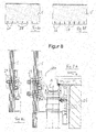
- Fig. 7 shows the profile system 100.
- the drainage pipe 24, which is arranged on the drainage connection 23, has a curved design and is designed so that the water flowing into the drainage channel 21 is directed away to a front side facing away from the building wall below the glass pane 5 is.
- the drain pipe 24 is kinked.
- An upper part, which leads out of the drain connection 23, is approximately perpendicular.
- Another part of the drainage pipe 24 is arranged approximately horizontally after the kink that has been formed. The direction of flow of the water diverted from the drainage channel 21 is therefore towards the side facing away from the building.
- There is a two-part design of a mounting bracket 10 which is placed on a balcony slab.
- Fig. 8 with the individual figures 8a to 8d represent different holder designs for the glass pane 5.
- Figure 8a represents the fastening of the glass pane 5 with several point fixings 27, and
- Figure 8b shows the fastening of the glass pane 5 with flat holders 28.
- Figure 8c provides execution after the Figure 8a with several point holders 27 in section and
- Figure 8d shows the embodiment according to Figure 8b with flat holders 28 also in section.
- the glass pane 5 is pulled downwards in this illustration so that it covers the entire construction of the profile system 100 in the direction of the side facing away from the building structure 26 in a visually uniform and advantageous manner, so that no separate cladding needs to be arranged.
- the glass pane 5 can, for example, be formed from a crystal-clear, transparent glass pane 5 in an upper area, which is opposite from the subsurface or floor on which the structure 26 is arranged, and in a lower area facing the floor, matt or translucent be designed so that the construction for fastening and draining the profile system 100 is "invisible" from the outside.
- the support posts or posts of the post railing can alternatively be supported so as to be displaceable via angles and thus be designed to be freely adjustable.
- no more holes have to be arranged in the surface elements or glass panes.
Landscapes
- Engineering & Computer Science (AREA)
- Architecture (AREA)
- Civil Engineering (AREA)
- Structural Engineering (AREA)
- Floor Finish (AREA)
Abstract
Description
- Die Erfindung betrifft ein Profilsystem zur Halterung eines Flächenelements für eine Absturzsicherung wie ein Geländer bzw. eine Geländerkonstruktion für Balkone oder Terrassen.
- Bekannt sind Vorrichtungen wie rahmenlose Ganzglasgeländer als Absturzsicherungen für Balkone, Terrassen oder Loggien von Gebäuden. Diese Ganzglasgeländer weisen eine Transparenz ohne störende Pfosten o.dgl. auf. Die Ganzglasgeländer können in Tragprofilen angeordnet und eingespannt gehalten sein. Als Tragprofile kommen insbesondere U-Profile zum Einsatz.
- Eine Balkonentwässerung erfolgt durch Balkonabläufe, durch Rinnen oder durch Wasserspeier. Bei allen Entwässerungen muss dafür gesorgt werden, dass ein ausreichendes Gefälle das Wasser vom Gebäude wegführt und dass die Abläufe, Rinnen oder Speier nicht verstopfen. Sonst besteht die Gefahr eines Rückstaus, der zu verschiedenen Schäden führen kann. Üblicherweise werden Balkonbodenplatten oder Terrassenböden beispielsweise aus Ortbeton hergestellt, die dann danach mit Regenrinnen und/oder Balkongeländern ausgestattet werden.
- Die
EP 2 025 827 A1 offenbart eine "Abschlussprofilanordnung für Balkone, Terrassen und dergleichen". Die Abschlussprofilanordnung für die senkrechten Stirnflächen von Balkonen oder Terrassen ermöglicht die Abdeckung durch ein Abschlussprofil, wobei die Stirnflächen zumindest in einem horizontalen Teilbereich vom Abschlussprofil abdeckt ist und das Abschlussprofil wenigstens eine Entwässerungsöffnung zur Abfuhr von anfallender Flüssigkeit aufweist. Das Abschlussprofil weist einen unterhalb der Balkonoberseite im Balkon verankerbaren Verankerungsschenkel und einen sich vom Verankerungsschenkel in Richtung zur Oberseite des Balkons vortretenden, die jeweilige Stirnfläche zumindest bereichsweise abdeckenden Abdeckschenkel auf. Des Weiteren ist eine langgestreckte Abdeckblende am Abschlussprofil angebracht, wobei ein Zwischenraum entsteht, über den anfallendes Wasser hindurchtreten kann. - Aus der
DE 195 35 187 A1 ist eine Lösung zur Anordnung einer Regenrinne an einer Balkonbodenplatte oder einer Terrasse bekannt. Bei dieser Lösung wird ein stirnseitig am Balkon angeordnetes, als Abschlussprofil für Balkone oder Terrassen einsetzbares Trägerprofil angeordnet, um an diesem ein gegenüber dem Trägerprofil relativ verschiebbar angeordnetes Rinnenprofil anzuordnen. Das Rinnenprofil kann dabei entsprechend der jeweils gewünschten Neigung in unterschiedlicher Höhe gegenüber dem Trägerprofil befestigt werden, so dass auch vor längeren Balkonfronten oder Terrassen die Regenrinnen das notwendige Gefälle aufweisen, wobei das Trägerprofil stirnseitig stets parallel zum Balkon- bzw. Terrassenboden befestigt wird. - Die
DE 10 2017 000 145 A1 offenbart ein "Rinnen- Abwassersystem zum Ableiten von Flächenwasser auf Flächen (Balkone, Terrassen, Flachdächern) im Außenbereich". Mit dem System können Rinnen-Abwassersysteme realisiert werden. Es ist ein Randträger zur Erstellung von Rinnen-Abwassersystemen ausgebildet. Der Randträger weist ein L-förmiges Grundprofil auf, zwischen dessen vertikalem Steg oben und einem vertikalen Steg unten eine horizontale Auflagefläche liegt. - Aus der
EP 0 731 236 B1 ist eine Befestigungsvorrichtung für tragende Geländerpfosten bekannt, bei der am Untergurt der Balkonplatte Profilstangen angeordnet werden, an denen stirnseitig abgerundete Halterelemente angeordnet sind, die auch an der Balkonplattenstirnseite anliegen, und gegen die jeweils eine Befestigungsvorrichtung für einen tragenden Geländerpfosten schwenkbar verspannt werden kann. - Diese genannten Lösungen sind sehr montageintensiv. Nach der Fertigstellung der Balkonbodenplatte bzw. der Terrassenbodenplatte wird die Regenrinne angebracht und nachfolgend die Balkongeländer befestigt und aufwändig ausgerichtet. In die bereits fertiggestellten Bodenplatten dürfen jegliche Befestigungselemente nur so eingebracht werden, dass die Bodenplatten durch das Einbringen von Befestigungselementen statisch nicht geschwächt und/oder derartig beschädigt werden, dass die Bodenplatten aufgrund dieser Beschädigungen dann unter Witterungseinfluss einem verstärkten Verschleiß unterworfen sind. Die genannten Anordnungen zur Entwässerung sind nach der Montage von davor angeordneten Brüstungen bzw. Balkongeländern üblicherweise nicht mehr zugänglich.
- Nachteilig an den bekannten Abschlussprofilanordnungen oder Abwassersystemen ist, dass sie getrennt von der Halterung der Balkonbrüstung bzw. Balustrade durch Trag- bzw. Halteprofile angebracht werden müssen und sowohl die aufwändige und teure Fertigung aus verschiedenen Teilen und der optische Eindruck, den diese Tragrahmen und die Abschlussprofilanordnungen vermitteln, soweit sie für Balkone und Terrassen eingesetzt werden, nicht den Ansprüchen an eine moderne Fassadengestaltung entspricht.
- Aufgabe der Erfindung ist es daher, einen Tragrahmen aus Profilen zur Verfügung zu stellen, der gegenüber den bekannten Tragrahmen eine einfache Montage und eine anspruchsvolle Fassadengestaltung ermöglicht.
- Die Erfindung wird durch die Merkmale des Hauptanspruchs offenbart. Ausführungsformen und Weiterbildungen sind Gegenstand der sich an den Hauptanspruch anschließenden weiteren Ansprüche.
- Es wird ein Profilsystem für eine Absturzsicherung wie ein Geländer bzw. eine Geländerkonstruktion mit einem Grundprofil, das die Funktion eines Halte- bzw. Tragprofils hat, in Kombination mit einer Entwässerungsvorrichtung zur kontrollierten Balkon- bzw. Terrassenentwässerung offenbart. Dabei werden erfindungsgemäß wenigstens zwei funktionell unterschiedliche Bauteile im Balkon- bzw. Terrassenbau zu einem Profilsystem kombiniert, so dass sowohl die Funktion eines Trag- bzw. Halteprofils und auch die Funktion der Entwässerung mit einer einfachen Montagemöglichkeit erfüllt werden.
- Es können dabei unterschiedliche Geländer-Varianten ausgebildet sein. Das Grund- bzw. Halteprofil selbst kann in einer einteiligen oder mehrteiligen Ausführungsform ausgebildet sein. Die einteilige Ausführung kann beispielsweise Geländerpfosten aufweisen. Die Profilstöße des Grundprofils sind beispielsweise dehnfähig mit EPDM-Formteilen und einer dauerelastischen Fuge ausgebildet. Das Grundprofil kann mit einer Absturzsicherung in Aluminium bzw. Stahl oder als Pfostengeländer ausgebildet sein. Die innere, in Richtung eines Bodens zeigende Kante des Grundprofils muss durch die erfindungsgemäße kombinierte Ausbildung in dem Profilsystem nicht mehr verblendet oder abgedeckt werden.
- Das Grundprofil ist mit der Entwässerungsvorrichtung mit einer offen zugänglichen wasserführenden Rinne zum genannten Profilsystem kombiniert. Die wasserführende Rinne ist insbesondere aus Aluminium, Metall bzw. Edelstahl oder auch Kunststoff ausgebildet. Das Wasser läuft in die wasserführende Rinne bzw. Abflussrinne, so dass eine definierte Entwässerung erfolgt. Das Wasser wird in dieser Rinne und nicht in einer Hohlkammer geführt. Es können seitliche Deckel bzw. Abdeckteile, die beispielsweise rund oder rechteckig ausgebildet sind, angeordnet werden, so dass eine gute Stabilität erzielt wird.
- Es kann auf der Rinne ein insbesondere herausnehmbares Schmutzgitter angeordnet werden. Das Schmutzgitter ist beispielsweise als Streckmetallgitter oder als Lochblech ausgebildet. Das Schmutzgitter kann eingelegt oder eingedickt werden. Es kann Löcher in Form eines Lochblechs oder Schlitze aufweisen. Die Löcher können bündig oder tiefer als die Seitenwände der Rinne ausgebildet sein. Das Schmutzgitter kann aus- bzw. einschwenkbar ausgebildet sein. Es ist aus einem dünnen Metall wie das genannte Lochblech oder aus einem Maschengewebe ausgebildet.
- Die Absturzsicherungen in einem Ausführungsbeispiel als Glasgeländer, die durch das Grundprofil gehalten werden, sind insbesondere aus bis zu 2 x 10 mm starken Verbundscheibengläsern mit einer Gesamtstärke von ca. 21,5 mm ausgebildet. Die Glasgeländer können durch in ihrer Ausrichtung im Grundprofil exakt feinjustiert werden.
- Das erfindungsgemäße Profilsystem mit dem Grundprofil und der Entwässerungsvorrichtung hat dabei den Vorteil, dass es variabel ausgestaltet werden kann und sehr einfach mit verschiedenen Befestigungskonsolen montiert werden kann. Dies kann beispielsweise mit einer verstellbaren Seitenmontage, einer verstellbaren Montage von oben oder durch die Kombination von zwei Befestigungskonsolen durch eine mehrfach justierbare Montage erfolgen. Die Höhe der Beläge der Balkone oder Terrassen sind in der Höhe variabel ausbildbar und durch die verschiedenen Ausbildungen und/oder Anordnungsmöglichkeiten des Profilsystems gut durch unterschiedliche Montagemöglichkeiten zu handhaben.
- Durch das erfindungsgemäße Profilsystem können die unteren Bereiche des Profilsystems, also die Entwässerungsrinne bzw. der Baukörper oder eine Unterkonstruktion, ohne eine Abdeckung durch eine angepasste Ausführungsform der Glasscheibe verblendet werden. Das erfolgt dadurch, dass das Flächenelement bzw. die Glasscheibe "heruntergezogen" wird, also über die Stirnseite hinweg reicht und dadurch eine gesonderte Abdeckung entfällt. Die Geländerkonstruktion kann dadurch beispielsweise auch ohne Pfosten angebracht werden.
- Weitere Vorteile und vorteilhafte Ausgestaltungen der Erfindung sind der nachfolgenden Figurenbeschreibung, den Zeichnungen und den Ansprüchen entnehmbar.
- Nachfolgend wird ein Ausführungsbeispiel der erfindungsgemäßen Lösung anhand der beigefügten schematischen Zeichnungen näher erläutert. Es zeigt:
- Fig. 1
- zeigt ein Profilsystem mit einem einteiligen Grundprofil und einer Befestigungskonsole für eine Seitenmontage,
- Fig. 2
- stellt das Profilsystem mit dem einteiligen Grundprofil mit der Befestigungskonsole für die Montage von oben dar,
- Fig. 3
- zeigt das Profilsystem mit dem einteiligen Grundprofil mit einer zweiteiligen justierbaren Befestigungskonsole,
- Fig. 4
- zeigt ein Profilsystem mit dem zweiteiligen Grundprofil mit einer aufgesetzten Absturzsicherung in Aluminium mit der Befestigungskonsole für die Seitenmontage auf einer Betonplatte,
- Fig. 5
- stellt ein Profilsystem mit einem zweiteiligen Grundprofil mit einer aufgesetzten Absturzsicherung in Stahl dar,
- Fig. 6a
- zeigt das Profilsystem mit dem zweiteiligen Grundprofil mit einem aufgesetzten Pfostengeländer,
- Fig. 6b
- zeigt das Profilsystem mit dem zweiteiligen Grundprofil mit dem aufgesetzten Pfostengeländer mit einem innenliegenden Flächenelement,
- Fig. 7
- zeigt das Profilsystem mit einem weiteren Ausführungsbeispiel der Ausbildung des Abflussrohrs,
- Fig. 8 a - d
- stellt das Profilsystem mit dem zweiteiligen Grundprofil mit direkt aufgesetzten Glasscheiben dar,
- Fig. 8a
- zeigt die Glasscheibe mit einem Punkthalter,
- Fig. 8b
- zeigt die Glasscheibe mit einem Flachhalter,
- Fig. 8 c
- stellt die Glasscheibe mit dem Punkthalter und
- Fig. 8d
- zeigt die Glasscheibe mit dem Flachhalter,
- In
Fig. 1 ist ein Profilsystem 100 mit einem einteiligen ersten Grundprofil 1 dargestellt. Im Grundprofil 1 wird ein Flächenelement 5, insbesondere eine Glasscheibe 5, klemmend gehalten. Das Flächenelement 5 kann alternativ auch aus Metall, Kunststoff o.dgl. ausgebildet sein. Es ist eine mit dem Grundprofil 1 verbundene Befestigungskonsole für eine Seitenmontage 7 angeordnet. Das einteilige erste Grundprofil 1 weist eine Blende in der seitlichen Richtung nach Außen 11 und eine Blende in der seitlichen Richtung nach innen 12 auf. Des Weiteren ist eine Untersichtblende 13 ausgebildet. - Die im erste Grundprofil 1 geklemmt gehaltene Glasscheibe 5 wird durch beidseitig der Glasscheibe 5 angeordnete Verglasungsdichtungen 15 gehalten. Die Glasscheibe 5 kann durch Stellelemente 16 für die Verglasung innerhalb des ersten Grundprofils 1 in ihrer vertikalen Ausrichtung eingestellt werden. Dadurch erfolgt eine exakte Feinjustierung der Glasscheibe 5 durch die Stellelemente. Die Glasscheibe 5 ist innerhalb eines im Bodenbereich des ersten einteiligen Grundprofils 1 angeordneten Klemmschuh 17 eingesetzt. Es erfolgt eine Grundprofil-Entwässerung 18 weg vom Bodenbereich des ersten Grundprofils 1.
- Das Profilsystem 100 mit dem ersten Grundprofil 1 und der Entwässerungsrinne 21 kann in die Befestigungskonsole für die Seitenmontage 7 eingehängt werden. Eine Aushebesicherung 14 verhindert das Aushängen des Profilsystems 100 aus der Befestigungskonsole für die Seitenmontage 7. Somit ermöglicht die Montage durch das Einhängen des Profilsystems 100 in Kombination mit der weiteren Einstellmöglichkeit der Justierung der Glasscheibe 5 durch die Stellelemente 16 für die Verglasung ein mehrfaches Einwirken auf die Anordnung, Positionierung und Einstellung der Glasscheibe 5 des Balkongeländers. Die gesamte Konstruktion ist in der Höhe in vertikaler Richtung verschiebbar. Dazu ist die Befestigungskonsole für die Seitenmontage 7 mit einer Riffelung ausgebildet. In die Befestigungskonsole für die Seitenmontage 7 ist eine erste Öffnung 29 eingebracht, deren Durchmesser etwas vergrößert gegenüber der Bohrung für eine einzubringende erste Befestigungsschraube 31 ist. An der einem Baukörper 26 abgewandten Seite wird eine erste Mutter 29 platziert, die zumindest an ihrem der Befestigungskonsole für die Seitenmontage 7 ebenfalls geriffelt ausgebildet ist. Nach dem Einschrauben der ersten Befestigungsschraube 31 ist ein gewisses Spiel vorhanden, um die Befestigungskonsole für die Seitenmontage 7 in der Vertikalrichtung nach oben bzw. unten zu verschieben. Somit kann die Höhe der Anordnung eingestellt werden. Der Vorteil dieser Ausbildung ist, dass bei Bedarf eine nachträgliche Einstellung durch eine Lockerung der Verschraubung und eine erneute Verschiebung möglich ist. Es werden keinerlei Verklebungen, Ausfüllungen o.dgl. zur Befestigung durchgeführt, so dass die Anordnung in begrenztem Rahmen verstellbar bleibt.
- Unterhalb eines Bodenbelags 19 eines Balkons oder einer Terrasse ist eine Entwässerungsrinne 21 ausgebildet. In die Entwässerungsrinne 21 ist ein Schmutzgitter 22 eingelegt oder eingeclipst. Das Schmutzgitter 22 kann ein- und ausschwenkbar ausgebildet sein. Das Schmutzgitter 22 kann aus Aluminium, Edelstahl, Kunststoff o.dgl. ausgebildet sein. Es ist ein Abflussstutzen 23 ausgebildet, der in ein Abflussrohr 24 mündet. Die Rinnenentwässerung durch den Abflussstutzen 23 ist für Standard-HT[Hochtemperatur]-Rohre geeignet. Diese HT-Rohre können für Abwasserleitungen verwendet werden. Sie sind bis ca. 95° wärmebeständig, insoweit dies benötigt wird. Die Pfeilrichtung A gibt die Fließrichtung des Wassers zur Entwässerung an.
-
Fig. 2 zeigt eine weitere Ausführungsform des Profilsystems 100. Dabei ist eine andere Befestigungskonsole für eine Montage von oben 8 dargestellt. An der Befestigungskonsole 8 ist in ihrem oberen, zum Balkonbelag 19 zeigenden Bereich ein sich in Horizontalrichtung erstreckender Schenkel der Befestigungskonsole für die Montage von oben 8 ausgebildet. Dieser Schenkel ist zusätzlich durch eine Verschraubung sicher befestigt. Dazu wird eine zweite Bohrung 32 eingebracht und an dem Schenkel eine zweite Mutter 22 angeordnet, die an dem geriffelt ausgebildeten Schenkel verstellbar ist. Die einzubringende zweite Befestigungsschraube 34 ist durch die Ausbildung der zweiten Bohrung 32, die ebenso wie die erste Bohrung 31 einen vergrößerten Durchmesser gegenüber der Bohrung für die einzubringende zweite Befestigungsschraube 34 hat, so ausgebildet, dass die Befestigungsschraube 34 beim Einbringen etwas Spiel hat und das Profilsystem 100 somit in zwei Richtungen verstellbar ist. Diese dargestellte Konstruktion des gezeigten Ausführungsbeispiels ist in horizontaler und in vertikaler Richtung verschieblich ausgebildet. Dies wird durch die Pfeile B und C dargestellt. -
Fig. 3 zeigt das Profilsystem 100 mit einem einteiligen ersten Grundprofil 1 mit einer zweiteiligen justierbaren Befestigungskonsole 9. Die Pfeilrichtung in zwei Richtungen an der zweiteiligen Befestigungskonsole 9 deutet die Verstellmöglichkeit in vertikaler Richtung an der Verschraubung in dieser Position durch die Pfeilrichtung B und die Verstellmöglichkeit in horizontaler Richtung durch die Pfeilrichtung C an. Die dicken Pfeile A an der Balkonoberfläche und im Balkonbelag 19 zeigen die Fließrichtung des Wassers. Am ersten Grundprofil 1 ist ein Lochblech 20 angeordnet. Zwischen diesem Lochblech 20 und dem Balkonbelag 19 kann das Wasser in Richtung der Entwässerungsrinne 21 abfließen und durch den Abflussstutzen 23 durch das Abflussrohr 24 abgeleitet werden. Das Profilsystem 100 ist in der Höhe und der Breite, also horizontal und vertikal verfahrbar. Es ist ein Schmutzgitter 22' angeordnet, dass abweichend von der Ausführung der Darstellungen ausFig. 1 undFig. 2 ausgebildet und angeordnet ist. - Im unteren Bereich unterhalb des Bodenbereichs des ersten Grundprofils 1 ist ein Wärmedämm-Verbundsystem 25 ausgebildet.
-
Fig. 4 zeigt ein Profilsystem 100 mit einem zweiteiligen zweiten Grundprofil 2 mit der Befestigungskonsole für die Seitenmontage 7. Durch eine Schraubverbindung ist der zweite Teil des zweiten Grundprofils 2 mit dem ersten Teil des Grundprofils 2, in dem die Glasscheibe 5 klemmend gehalten ist, verbunden. Dieser erste Teil des zweiten zweiteiligen Grundprofils 2 ist mit einem nach außen, vom Gebäude bzw. dem Balkonbelag 19 weg zeigenden Schenkel, als "Absturzsicherung" aus Aluminium 3 bezeichnet, ausgebildet. Es ist eine Untersichtblende 13 angeordnet. Die Glasscheibe 5 kann durch die Spreizung des Stellelements für die Verglasung 16 durch die einzubringende Schraube innerhalb des ersten Teils des zweiteiligen zweiten Grundprofils 2 feinjustiert und in ihrer Vertikalstellung zusätzlich verstellt werden. -
Fig. 5 stellt ein Profilsystem 100 mit einem zweiteiligen zweiten Grundprofil 2 mit einer aufgesetzten Absturzsicherung in Stahl 4 dar. Am zweiten Teil des zweiteiligen Grundprofils 2, das zwischen dem ersten Teil des Grundprofils 2, in dem die Glasscheibe 5 klemmend gehalten ist, und dem Balkonbelag 19 ausgebildet ist, ist eine Blende innen 12 in einem oberen, in Richtung der Oberkante der Glasscheibe 5 zeigenden Bereich des Grundprofils 2 um einen abweichend ausgestalteten Schenkel herumreichend ausgebildet. -
Fig. 6a zeigt das Profilsystem 100 mit dem zweiteiligen zweiten Grundprofil 2. Der zweite Teil des Grundprofils 2 weist ein aufgesetztes Pfostengeländer 6 auf. Bei einem Pfostengeländer allgemein verlaufen die Füllprofile lotrecht. Diese Ausführungsform wird insbesondere bei Pfosten bzw. runden oder vierkantigen Stäben und verschiedenen Hohl- und Vollprofilen verwendet. Es ist also ein Pfostengeländer 6 ausgebildet. Des Weiteren ist die Befestigungskonsole zur Seitenmontage 7 ausgebildet. Diese Befestigungskonsole 7 wird durch die Aushebesicherung 14 in ihrer Position gesichert. Die Entwässerungsrinne 21 ist von außen bzw. von oben, also der Oberseite des Balkonbelags 19 her, zugänglich. Das Pfostengeländer 6 weist eine Füllung insbesondere mit einer Glasscheibe 5 auf. -
Fig. 6b zeigt das Profilsystem 100 mit dem zweiteiligen zweiten Grundprofil 2 und dem aufgesetzten Pfostengeländer 6. Es ist eine innenliegende Glasscheibe als Flächenelement 5 angeordnet und linienförmig über die Höhenkanten gelagert. Die Pfosten des Pfostengeländers 6 sind frei horizontal im Profilsystem 100 positioniert. Das Flächenelement 5 bzw. die Glasscheibe ist linienförmig am Tragpfosten bzw. Pfosten des Pfostengeländers 6 gelagert. -
Fig. 7 stellt das Profilsystem 100 dar. Das Abflussrohr 24, das an dem Abflussstutzen 23 angeordnet ist, weist eine gebogene Ausbildung auf und ist so ausgebildet, dass das in die Entwässerungsrinne 21 einfließende Wasser zu einer der Gebäudewand abgewandten Vorderseite unterhalb der Glasscheibe 5 weggeleitet ist. Das Abflussrohr 24 ist abgeknickt ausgebildet. Ein oberer Teil, der aus dem Abflussstutzen 23 herausführt, ist in etwa senkrecht ausgebildet. Ein weiterer Teil des Abflussrohrs 24 ist nach dem ausgebildeten Knick in etwa waagerecht angeordnet. Die Fließrichtung des abgeleiteten Wassers aus der Entwässerungsrinne 21 ist daher hin zur der dem Gebäude abgewandten Seite. Es ist eine zweiteilige Ausbildung einer Befestigungskonsole 10 ausgebildet, die auf eine Balkonplatte aufgesetzt ist. -
Fig. 8 mit den Einzelfiguren 8a bis 8d stellt unterschiedliche Halter-Ausbildungen für die Glasscheibe 5 dar. -
Fig. 8a stellt die Befestigung der Glasscheibe 5 mit mehreren Punkthaltern 27 dar, und -
Fig. 8b zeigt die Befestigung der Glasscheibe 5 mit Flachhaltern 28. -
Fig. 8c stellt die Ausführung nach derFig. 8a mit mehreren Punkthaltern 27 im Schnitt dar und -
Fig. 8d zeigt die Ausführungsform nach derFig. 8b mit Flachhaltern 28 ebenfalls im Schnitt. Die Glasscheibe 5 ist in dieser Darstellung nach unten gezogen, so dass sie die gesamte Konstruktion des Profilsystems 100 in Richtung der vom Baukörper 26 nach außen abgewandten Seite optisch einheitlich und vorteilhaft abdeckt, so dass keine gesonderte Verkleidung mehr angeordnet werden muss. Die Glasscheibe 5 kann beispielsweise in einem oberen Bereich, der vom Untergrund bzw. Boden, auf dem der Baukörper 26 angeordnet ist, entgegengesetzt ist, aus einer glasklaren, durchsichtigen Glasscheibe 5 ausgebildet und in einem unteren, zum Boden zeigenden Bereich, matt bzw. durchscheinend ausgebildet sein, so dass die Konstruktion zur Befestigung und Entwässerung des Profilsystems 100 von außen "unsichtbar" verkleidet ist. - Die Tragpfosten bzw. Pfosten des Pfostengeländers können alternativ über Winkel verschieblich gelagert und dadurch frei stellbar ausgebildet sein. Bei diesem Ausführungsbeispiel müssen in den Flächenelementen bzw. Glasscheiben keine Bohrungen mehr angeordnet werden.
- Alle in der Beschreibung, den nachfolgenden Ansprüchen und den Zeichnungen dargestellten Merkmale können sowohl einzeln als auch in beliebiger Kombination miteinander erfindungswesentlich sein.
-
- 1
- Erstes Grundprofil einteilig
- 2
- Zweites Grundprofil zweiteilig
- 3
- Absturzsicherung Aluminium
- 4
- Absturzsicherung Stahl
- 5
- Flächenelement
- 6
- Pfostengeländer mit Füllung
- 7
- Befestigungskonsole Seitenmontage
- 8
- Befestigungskonsole Montage von oben
- 9
- Zweiteilige Befestigungskonsole mit Montage
- 10
- Befestigungskonsole auf Balkonplatte
- 11
- Blende außen
- 12
- Blende innen
- 13
- Untersichtblende
- 14
- Aushebesicherung
- 15
- Verglasungsdichtungen
- 16
- Stellelement für Verglasung
- 17
- Klemmschuh
- 18
- Grundprofil-Entwässerung
- 19
- Balkonbelag
- 20
- Lochblech
- 21
- Entwässerungsvorrichtung: Entwässerungsrinne
- 22
- Schmutzgitter
- 22'
- Schmutzgitter
- 23
- Abflussstutzen
- 24
- Abflussrohr
- 25
- Wärmedämmverbundsystem
- 26
- Baukörper
- 27
- Punkthalter
- 28
- Flachhalter
- 29
- Erste Bohrung
- 30
- Erste Mutter
- 31
- Erste Befestigungsschraube
- 32
- Zweite Bohrung
- 33
- Zweite Mutter
- 34
- Zweite Befestigungsschraube
- A
- Pfeil Fließrichtung Wasser
- B
- Pfeil Bewegungsrichtung Profilsystem 100 vertikal
- C
- Pfeil Bewegungsrichtung Profilsystem 100 horizontal
- D
- Pfeil Bewegungsrichtung Feinjustierung Flächenelement
- 100
- Profilsystem
Claims (18)
- Profilsystem (100) zur Halterung eines Flächenelements (5) zur Anordnung an einem Balkon oder einer Terrasse eines Gebäudes, dadurch gekennzeichnet, dass das Profilsystem (100) ein erstes Grundprofil (1) oder ein zweites Grundprofil (2), das die Funktion eines Halte- oder Tragprofils für das Flächenelement (5) hat, sowie eine damit kombinierte Entwässerungsvorrichtung (21) zur kontrollierten Balkon- oder Terrassenentwässerung aufweist.
- Profilsystem (100) nach Anspruch 1, dadurch gekennzeichnet, dass die Entwässerungsvorrichtung (21) als Entwässerungsrinne (21) und aus der Richtung eines Balkonbelags (19) frei zugänglich ausgebildet ist.
- Profilsystem (100) nach einem der vorhergehenden Ansprüche 1 oder 2, dadurch gekennzeichnet, dass das Flächenelement (5) durch Stellelemente (16) feinjustierbar ist.
- Profilsystem (100) nach Anspruch 3, dadurch gekennzeichnet, dass die Montage des Profilsystems (100) durch Einhängen über eine verstellbare Befestigungskonsole zur Seitenmontage (7), eine verstellbare Befestigungskonsole zur Montage von oben (8), eine zweiteilige Befestigungskonsole (9) oder eine zweiteilige Befestigungskonsole, die auf eine Balkonplatte aufgesetzt ist (10) mit jeweils mehrfachen Justiermöglichkeiten, erfolgt.
- Profilsystem (100) nach Anspruch 4, dadurch gekennzeichnet, dass durch eine Kombination der Verstellbarkeiten durch eine Feinjustierung des Flächenelements (5) und/oder mehrfachen Justierungen der Befestigungskonsole zur Seitenmontage (7) oder der Befestigungskonsolen zur Montage von oben (8) oder der zweiteiligen Befestigungskonsole (9) oder der zweiteiligen Befestigungskonsole, die auf eine Balkonplatte aufgesetzt ist (10), befestigungsbauliche Toleranzen aus dem Baukörper (26) ausgeglichen werden und hierdurch ein Gefälle der Entwässerungsrinne (21) zu einem Abflussstutzen (23) mit einer einstellbaren Neigung ausgebildet wird, so dass dadurch eine gerichtete Wasserabführung erfolgt.
- Profilsystem (100) nach einem der vorhergehenden Ansprüche, dadurch gekennzeichnet, dass die Entwässerungsvorrichtung (21) ein Schmutzgitter (22, 22') aufweist.
- Profilsystem (100) nach Anspruch 6, dadurch gekennzeichnet, dass das Schmutzgitter (22, 22') herausnehmbar oder aus- und einschwenkbar ausgebildet ist.
- Profilsystem (100) nach einem der vorhergehenden Ansprüche, dadurch gekennzeichnet, dass das erste Grundprofil (1) einteilig ausgebildet ist.
- Profilsystem (100) nach einem der vorhergehenden Ansprüche 1 bis 7, dadurch gekennzeichnet, dass das zweite Grundprofil (2) zweiteilig ausgebildet ist.
- Profilsystem (100) nach einem der vorhergehenden Ansprüche, dadurch gekennzeichnet, dass das erste und das zweite Grundprofil (1, 2) eine Absturzsicherung aus Aluminium (3) oder eine Absturzsicherung aus Stahl (4) oder ein Pfostengeländer (6) umfasst.
- Profilsystem (100) nach einem der vorhergehenden Ansprüche, dadurch gekennzeichnet, dass eine Aushebesicherung (14) ausgebildet ist.
- Profilsystem (100) nach einem der vorhergehenden Ansprüche 2 bis 11, dadurch gekennzeichnet, dass die Entwässerung durch die Entwässerungsrinne (21) in den Abflussstutzen (23) und weiter in ein Abflussrohr (24) erfolgt.
- Profilsystem (100) nach Anspruch 12, dadurch gekennzeichnet, dass das Abflussrohr (24) senkrecht in Richtung eines Untergrunds des Gebäudes oder gebogen und teilweise horizontal vom Gebäude wegführend ausgebildet ist.
- Profilsystem (100) nach einem der vorhergehenden Ansprüche, dadurch gekennzeichnet, dass das Flächenelement (5) als Glasscheibe (5) ausgebildet ist.
- Profilsystem (100) nach einem der vorhergehenden Ansprüche, dadurch gekennzeichnet, dass das Flächenelement (5) im Grundprofil (1, 2) geklemmt gehalten oder mittels Punkthaltern (27) oder Flachhaltern (28) befestigt oder an einem Pfostengeländer (6) angeordnet ist.
- Profilsystem (100) nach einem der vorhergehenden Ansprüche, dadurch gekennzeichnet, dass an einer vom Gebäude weg zeigenden Seite des Grundprofils (1, 2) eine Blende außen (11) angeordnet ist.
- Profilsystem (100) nach einem der Ansprüche 1 bis 15, dadurch gekennzeichnet, dass an einer zum Balkonbelag (19) zeigenden Seite des Grundprofils (1, 2) eine Blende innen (12) angeordnet ist.
- Profilsystem (100) nach einem der vorhergehenden Ansprüche, dadurch gekennzeichnet, dass in Richtung auf einen Boden unterhalb des Gebäudes eine Untersichtsblende (13) angeordnet ist.
Priority Applications (2)
| Application Number | Priority Date | Filing Date | Title |
|---|---|---|---|
| EP19204645.6A EP3812531B1 (de) | 2019-10-22 | 2019-10-22 | Profilsystem zur halterung eines flächenelements |
| SI201930774T SI3812531T1 (sl) | 2019-10-22 | 2019-10-22 | Profilni sistem za zadrževanje ravnega elementa |
Applications Claiming Priority (1)
| Application Number | Priority Date | Filing Date | Title |
|---|---|---|---|
| EP19204645.6A EP3812531B1 (de) | 2019-10-22 | 2019-10-22 | Profilsystem zur halterung eines flächenelements |
Publications (2)
| Publication Number | Publication Date |
|---|---|
| EP3812531A1 true EP3812531A1 (de) | 2021-04-28 |
| EP3812531B1 EP3812531B1 (de) | 2024-05-01 |
Family
ID=68392706
Family Applications (1)
| Application Number | Title | Priority Date | Filing Date |
|---|---|---|---|
| EP19204645.6A Active EP3812531B1 (de) | 2019-10-22 | 2019-10-22 | Profilsystem zur halterung eines flächenelements |
Country Status (2)
| Country | Link |
|---|---|
| EP (1) | EP3812531B1 (de) |
| SI (1) | SI3812531T1 (de) |
Cited By (4)
| Publication number | Priority date | Publication date | Assignee | Title |
|---|---|---|---|---|
| EP4230819A1 (de) * | 2022-02-19 | 2023-08-23 | René Bangratz | Nutprofil |
| EP4230820A1 (de) * | 2022-02-19 | 2023-08-23 | René Bangratz | Basisprofil mit mehrfachnutenprofil |
| US20240076878A1 (en) * | 2022-09-07 | 2024-03-07 | Bendheim Wall Systems Inc. | Fascia Rail System |
| EP4585765A1 (de) | 2024-01-11 | 2025-07-16 | Arthur Weber AG | Anschlussvorrichtung zur befestigung eines geländers |
Citations (8)
| Publication number | Priority date | Publication date | Assignee | Title |
|---|---|---|---|---|
| EP0731236A1 (de) | 1995-03-10 | 1996-09-11 | Horizal | Befestigungsvorrichtung am Deckenunterbau für tragende Geländerpfosten |
| DE19535187A1 (de) | 1995-09-22 | 1997-03-27 | Schlueter Systems Gmbh | Trägerprofil zum Anbringen an einer Wand |
| DE19612505A1 (de) * | 1996-03-29 | 1997-10-02 | Walter Gutjahr | Entwässerungssystem für Balkone mit Brüstung |
| DE29714562U1 (de) * | 1997-08-14 | 1997-10-16 | Dorenwendt Wolfgang | Befestigungssystem für Regenrinnen |
| EP2025827A1 (de) | 2007-08-16 | 2009-02-18 | Walter Gutjahr | Abschlussprofilanordnung für Balkone, Terrassen und dergleichen |
| EP3056632A1 (de) * | 2015-02-14 | 2016-08-17 | Klaus Peter Abel | Randeinfassung für balkon- und terrassenböden |
| EP3067487A1 (de) * | 2015-03-09 | 2016-09-14 | Pure Vista Ltd | System und verfahren zur anpassung der ausrichtung einer platte |
| DE102017000145A1 (de) | 2017-01-10 | 2018-07-12 | Manuel Wolf | Rinnen- Abwassersystem zum Ableiten von Flächenwasser auf Flächen (Balkone, Terrassen, Flachdächern ..) im Außenbereich. Mit dem System können Rinnen- Abwassersysteme in allen Abmessungen sehr einfach und schnell realisiert werden. |
-
2019
- 2019-10-22 EP EP19204645.6A patent/EP3812531B1/de active Active
- 2019-10-22 SI SI201930774T patent/SI3812531T1/sl unknown
Patent Citations (8)
| Publication number | Priority date | Publication date | Assignee | Title |
|---|---|---|---|---|
| EP0731236A1 (de) | 1995-03-10 | 1996-09-11 | Horizal | Befestigungsvorrichtung am Deckenunterbau für tragende Geländerpfosten |
| DE19535187A1 (de) | 1995-09-22 | 1997-03-27 | Schlueter Systems Gmbh | Trägerprofil zum Anbringen an einer Wand |
| DE19612505A1 (de) * | 1996-03-29 | 1997-10-02 | Walter Gutjahr | Entwässerungssystem für Balkone mit Brüstung |
| DE29714562U1 (de) * | 1997-08-14 | 1997-10-16 | Dorenwendt Wolfgang | Befestigungssystem für Regenrinnen |
| EP2025827A1 (de) | 2007-08-16 | 2009-02-18 | Walter Gutjahr | Abschlussprofilanordnung für Balkone, Terrassen und dergleichen |
| EP3056632A1 (de) * | 2015-02-14 | 2016-08-17 | Klaus Peter Abel | Randeinfassung für balkon- und terrassenböden |
| EP3067487A1 (de) * | 2015-03-09 | 2016-09-14 | Pure Vista Ltd | System und verfahren zur anpassung der ausrichtung einer platte |
| DE102017000145A1 (de) | 2017-01-10 | 2018-07-12 | Manuel Wolf | Rinnen- Abwassersystem zum Ableiten von Flächenwasser auf Flächen (Balkone, Terrassen, Flachdächern ..) im Außenbereich. Mit dem System können Rinnen- Abwassersysteme in allen Abmessungen sehr einfach und schnell realisiert werden. |
Cited By (4)
| Publication number | Priority date | Publication date | Assignee | Title |
|---|---|---|---|---|
| EP4230819A1 (de) * | 2022-02-19 | 2023-08-23 | René Bangratz | Nutprofil |
| EP4230820A1 (de) * | 2022-02-19 | 2023-08-23 | René Bangratz | Basisprofil mit mehrfachnutenprofil |
| US20240076878A1 (en) * | 2022-09-07 | 2024-03-07 | Bendheim Wall Systems Inc. | Fascia Rail System |
| EP4585765A1 (de) | 2024-01-11 | 2025-07-16 | Arthur Weber AG | Anschlussvorrichtung zur befestigung eines geländers |
Also Published As
| Publication number | Publication date |
|---|---|
| EP3812531B1 (de) | 2024-05-01 |
| SI3812531T1 (sl) | 2024-08-30 |
Similar Documents
| Publication | Publication Date | Title |
|---|---|---|
| DE102019007427A1 (de) | Profilsystem zur Halterung eines Flächenelements | |
| EP3812531B1 (de) | Profilsystem zur halterung eines flächenelements | |
| DE102015001891B4 (de) | Randeinfassung für Balkon- und Terrassenböden | |
| DE2142733C3 (de) | Eindeckrahmen für in der Dachfläche liegende Dachfenster | |
| EP0725194B1 (de) | Entwässerungssytem für Balkone | |
| EP4257764A1 (de) | Entwässerungsvorrichtung für eine bauseitige montage und entwässerungssystem | |
| EP3418471B1 (de) | Abdeckung für eine glasgeländervorrichtung | |
| CH701903A2 (de) | Verkleidungs- und Entwässerungselement für die Stirnseiten von Bauteilen wie Balkone, Terrassen, Laubengänge, Flachdächer und dergleichen. | |
| AT12302U1 (de) | Rollladen | |
| DE19520419C2 (de) | Befestigungsvorrichtung für Balkonverkleidungselemente | |
| DE29716050U1 (de) | Balkon zur Anordnung vor der Fassade eines Bauwerkes | |
| EP4230820A1 (de) | Basisprofil mit mehrfachnutenprofil | |
| EP3075920B1 (de) | Abschlussleiste und verfahren zum montieren einer abschlussleiste | |
| DE19941462B4 (de) | Geländerstütze mit Dachrinnenprofil | |
| DE102005031674B4 (de) | Anbaubalkon und Wassereinlaufkasten für denselben | |
| DE102021121506B4 (de) | Dachrandabschluss für Flachdächer oder flachgeneigte Dächer | |
| EP4585765A1 (de) | Anschlussvorrichtung zur befestigung eines geländers | |
| DE29806721U1 (de) | Balkonkonstruktion | |
| DE29906821U1 (de) | Entwässerungsablauf zum Anschluß an Gebäudekanten | |
| WO2004104318A1 (de) | Abdeckung für eine fläche von balkonen, böden, dächern oder fassaden | |
| CH716033B1 (de) | Abschlussmodul für ein Flachdach mit Aussenwärmedämmung zur Befestigung eines Geländers. | |
| DE102017131240A1 (de) | Abdeckung für eine Glasgeländervorrichtung | |
| DE102022000750A1 (de) | Basisprofil mit Mehrfachnutenprofil | |
| DE102013102617A1 (de) | Verfahren zum Abschirmen einer freien Fläche | |
| DE102017000145A1 (de) | Rinnen- Abwassersystem zum Ableiten von Flächenwasser auf Flächen (Balkone, Terrassen, Flachdächern ..) im Außenbereich. Mit dem System können Rinnen- Abwassersysteme in allen Abmessungen sehr einfach und schnell realisiert werden. |
Legal Events
| Date | Code | Title | Description |
|---|---|---|---|
| PUAI | Public reference made under article 153(3) epc to a published international application that has entered the european phase |
Free format text: ORIGINAL CODE: 0009012 |
|
| STAA | Information on the status of an ep patent application or granted ep patent |
Free format text: STATUS: THE APPLICATION HAS BEEN PUBLISHED |
|
| AK | Designated contracting states |
Kind code of ref document: A1 Designated state(s): AL AT BE BG CH CY CZ DE DK EE ES FI FR GB GR HR HU IE IS IT LI LT LU LV MC MK MT NL NO PL PT RO RS SE SI SK SM TR |
|
| AX | Request for extension of the european patent |
Extension state: BA ME |
|
| STAA | Information on the status of an ep patent application or granted ep patent |
Free format text: STATUS: REQUEST FOR EXAMINATION WAS MADE |
|
| 17P | Request for examination filed |
Effective date: 20210803 |
|
| RBV | Designated contracting states (corrected) |
Designated state(s): AL AT BE BG CH CY CZ DE DK EE ES FI FR GB GR HR HU IE IS IT LI LT LU LV MC MK MT NL NO PL PT RO RS SE SI SK SM TR |
|
| REG | Reference to a national code |
Ref country code: DE Ref legal event code: R079 Ref country code: DE Ref legal event code: R079 Ref document number: 502019011170 Country of ref document: DE Free format text: PREVIOUS MAIN CLASS: E04F0011180000 Ipc: E04D0013064000 |
|
| GRAP | Despatch of communication of intention to grant a patent |
Free format text: ORIGINAL CODE: EPIDOSNIGR1 |
|
| STAA | Information on the status of an ep patent application or granted ep patent |
Free format text: STATUS: GRANT OF PATENT IS INTENDED |
|
| RIC1 | Information provided on ipc code assigned before grant |
Ipc: E04F 11/18 20060101ALI20231218BHEP Ipc: E04D 13/064 20060101AFI20231218BHEP |
|
| INTG | Intention to grant announced |
Effective date: 20240118 |
|
| GRAS | Grant fee paid |
Free format text: ORIGINAL CODE: EPIDOSNIGR3 |
|
| GRAA | (expected) grant |
Free format text: ORIGINAL CODE: 0009210 |
|
| STAA | Information on the status of an ep patent application or granted ep patent |
Free format text: STATUS: THE PATENT HAS BEEN GRANTED |
|
| AK | Designated contracting states |
Kind code of ref document: B1 Designated state(s): AL AT BE BG CH CY CZ DE DK EE ES FI FR GB GR HR HU IE IS IT LI LT LU LV MC MK MT NL NO PL PT RO RS SE SI SK SM TR |
|
| REG | Reference to a national code |
Ref country code: GB Ref legal event code: FG4D Free format text: NOT ENGLISH |
|
| REG | Reference to a national code |
Ref country code: CH Ref legal event code: EP |
|
| REG | Reference to a national code |
Ref country code: IE Ref legal event code: FG4D Free format text: LANGUAGE OF EP DOCUMENT: GERMAN |
|
| REG | Reference to a national code |
Ref country code: DE Ref legal event code: R096 Ref document number: 502019011170 Country of ref document: DE |
|
| REG | Reference to a national code |
Ref country code: NL Ref legal event code: FP |
|
| REG | Reference to a national code |
Ref country code: LT Ref legal event code: MG9D |
|
| PG25 | Lapsed in a contracting state [announced via postgrant information from national office to epo] |
Ref country code: IS Free format text: LAPSE BECAUSE OF FAILURE TO SUBMIT A TRANSLATION OF THE DESCRIPTION OR TO PAY THE FEE WITHIN THE PRESCRIBED TIME-LIMIT Effective date: 20240901 |
|
| PG25 | Lapsed in a contracting state [announced via postgrant information from national office to epo] |
Ref country code: BG Free format text: LAPSE BECAUSE OF FAILURE TO SUBMIT A TRANSLATION OF THE DESCRIPTION OR TO PAY THE FEE WITHIN THE PRESCRIBED TIME-LIMIT Effective date: 20240501 |
|
| PG25 | Lapsed in a contracting state [announced via postgrant information from national office to epo] |
Ref country code: FI Free format text: LAPSE BECAUSE OF FAILURE TO SUBMIT A TRANSLATION OF THE DESCRIPTION OR TO PAY THE FEE WITHIN THE PRESCRIBED TIME-LIMIT Effective date: 20240501 Ref country code: HR Free format text: LAPSE BECAUSE OF FAILURE TO SUBMIT A TRANSLATION OF THE DESCRIPTION OR TO PAY THE FEE WITHIN THE PRESCRIBED TIME-LIMIT Effective date: 20240501 |
|
| PG25 | Lapsed in a contracting state [announced via postgrant information from national office to epo] |
Ref country code: GR Free format text: LAPSE BECAUSE OF FAILURE TO SUBMIT A TRANSLATION OF THE DESCRIPTION OR TO PAY THE FEE WITHIN THE PRESCRIBED TIME-LIMIT Effective date: 20240802 |
|
| PG25 | Lapsed in a contracting state [announced via postgrant information from national office to epo] |
Ref country code: PT Free format text: LAPSE BECAUSE OF FAILURE TO SUBMIT A TRANSLATION OF THE DESCRIPTION OR TO PAY THE FEE WITHIN THE PRESCRIBED TIME-LIMIT Effective date: 20240902 |
|
| PG25 | Lapsed in a contracting state [announced via postgrant information from national office to epo] |
Ref country code: ES Free format text: LAPSE BECAUSE OF FAILURE TO SUBMIT A TRANSLATION OF THE DESCRIPTION OR TO PAY THE FEE WITHIN THE PRESCRIBED TIME-LIMIT Effective date: 20240501 |
|
| PG25 | Lapsed in a contracting state [announced via postgrant information from national office to epo] |
Ref country code: PL Free format text: LAPSE BECAUSE OF FAILURE TO SUBMIT A TRANSLATION OF THE DESCRIPTION OR TO PAY THE FEE WITHIN THE PRESCRIBED TIME-LIMIT Effective date: 20240501 |
|
| PG25 | Lapsed in a contracting state [announced via postgrant information from national office to epo] |
Ref country code: LV Free format text: LAPSE BECAUSE OF FAILURE TO SUBMIT A TRANSLATION OF THE DESCRIPTION OR TO PAY THE FEE WITHIN THE PRESCRIBED TIME-LIMIT Effective date: 20240501 |
|
| PG25 | Lapsed in a contracting state [announced via postgrant information from national office to epo] |
Ref country code: PT Free format text: LAPSE BECAUSE OF FAILURE TO SUBMIT A TRANSLATION OF THE DESCRIPTION OR TO PAY THE FEE WITHIN THE PRESCRIBED TIME-LIMIT Effective date: 20240902 Ref country code: PL Free format text: LAPSE BECAUSE OF FAILURE TO SUBMIT A TRANSLATION OF THE DESCRIPTION OR TO PAY THE FEE WITHIN THE PRESCRIBED TIME-LIMIT Effective date: 20240501 Ref country code: NO Free format text: LAPSE BECAUSE OF FAILURE TO SUBMIT A TRANSLATION OF THE DESCRIPTION OR TO PAY THE FEE WITHIN THE PRESCRIBED TIME-LIMIT Effective date: 20240801 Ref country code: LV Free format text: LAPSE BECAUSE OF FAILURE TO SUBMIT A TRANSLATION OF THE DESCRIPTION OR TO PAY THE FEE WITHIN THE PRESCRIBED TIME-LIMIT Effective date: 20240501 Ref country code: IS Free format text: LAPSE BECAUSE OF FAILURE TO SUBMIT A TRANSLATION OF THE DESCRIPTION OR TO PAY THE FEE WITHIN THE PRESCRIBED TIME-LIMIT Effective date: 20240901 Ref country code: HR Free format text: LAPSE BECAUSE OF FAILURE TO SUBMIT A TRANSLATION OF THE DESCRIPTION OR TO PAY THE FEE WITHIN THE PRESCRIBED TIME-LIMIT Effective date: 20240501 Ref country code: GR Free format text: LAPSE BECAUSE OF FAILURE TO SUBMIT A TRANSLATION OF THE DESCRIPTION OR TO PAY THE FEE WITHIN THE PRESCRIBED TIME-LIMIT Effective date: 20240802 Ref country code: FI Free format text: LAPSE BECAUSE OF FAILURE TO SUBMIT A TRANSLATION OF THE DESCRIPTION OR TO PAY THE FEE WITHIN THE PRESCRIBED TIME-LIMIT Effective date: 20240501 Ref country code: ES Free format text: LAPSE BECAUSE OF FAILURE TO SUBMIT A TRANSLATION OF THE DESCRIPTION OR TO PAY THE FEE WITHIN THE PRESCRIBED TIME-LIMIT Effective date: 20240501 Ref country code: BG Free format text: LAPSE BECAUSE OF FAILURE TO SUBMIT A TRANSLATION OF THE DESCRIPTION OR TO PAY THE FEE WITHIN THE PRESCRIBED TIME-LIMIT Effective date: 20240501 Ref country code: RS Free format text: LAPSE BECAUSE OF FAILURE TO SUBMIT A TRANSLATION OF THE DESCRIPTION OR TO PAY THE FEE WITHIN THE PRESCRIBED TIME-LIMIT Effective date: 20240801 |
|
| PG25 | Lapsed in a contracting state [announced via postgrant information from national office to epo] |
Ref country code: DK Free format text: LAPSE BECAUSE OF FAILURE TO SUBMIT A TRANSLATION OF THE DESCRIPTION OR TO PAY THE FEE WITHIN THE PRESCRIBED TIME-LIMIT Effective date: 20240501 |
|
| PG25 | Lapsed in a contracting state [announced via postgrant information from national office to epo] |
Ref country code: EE Free format text: LAPSE BECAUSE OF FAILURE TO SUBMIT A TRANSLATION OF THE DESCRIPTION OR TO PAY THE FEE WITHIN THE PRESCRIBED TIME-LIMIT Effective date: 20240501 |
|
| PG25 | Lapsed in a contracting state [announced via postgrant information from national office to epo] |
Ref country code: CZ Free format text: LAPSE BECAUSE OF FAILURE TO SUBMIT A TRANSLATION OF THE DESCRIPTION OR TO PAY THE FEE WITHIN THE PRESCRIBED TIME-LIMIT Effective date: 20240501 |
|
| PG25 | Lapsed in a contracting state [announced via postgrant information from national office to epo] |
Ref country code: SK Free format text: LAPSE BECAUSE OF FAILURE TO SUBMIT A TRANSLATION OF THE DESCRIPTION OR TO PAY THE FEE WITHIN THE PRESCRIBED TIME-LIMIT Effective date: 20240501 Ref country code: RO Free format text: LAPSE BECAUSE OF FAILURE TO SUBMIT A TRANSLATION OF THE DESCRIPTION OR TO PAY THE FEE WITHIN THE PRESCRIBED TIME-LIMIT Effective date: 20240501 |
|
| PG25 | Lapsed in a contracting state [announced via postgrant information from national office to epo] |
Ref country code: SM Free format text: LAPSE BECAUSE OF FAILURE TO SUBMIT A TRANSLATION OF THE DESCRIPTION OR TO PAY THE FEE WITHIN THE PRESCRIBED TIME-LIMIT Effective date: 20240501 |
|
| PG25 | Lapsed in a contracting state [announced via postgrant information from national office to epo] |
Ref country code: SM Free format text: LAPSE BECAUSE OF FAILURE TO SUBMIT A TRANSLATION OF THE DESCRIPTION OR TO PAY THE FEE WITHIN THE PRESCRIBED TIME-LIMIT Effective date: 20240501 Ref country code: SK Free format text: LAPSE BECAUSE OF FAILURE TO SUBMIT A TRANSLATION OF THE DESCRIPTION OR TO PAY THE FEE WITHIN THE PRESCRIBED TIME-LIMIT Effective date: 20240501 Ref country code: RO Free format text: LAPSE BECAUSE OF FAILURE TO SUBMIT A TRANSLATION OF THE DESCRIPTION OR TO PAY THE FEE WITHIN THE PRESCRIBED TIME-LIMIT Effective date: 20240501 Ref country code: EE Free format text: LAPSE BECAUSE OF FAILURE TO SUBMIT A TRANSLATION OF THE DESCRIPTION OR TO PAY THE FEE WITHIN THE PRESCRIBED TIME-LIMIT Effective date: 20240501 Ref country code: DK Free format text: LAPSE BECAUSE OF FAILURE TO SUBMIT A TRANSLATION OF THE DESCRIPTION OR TO PAY THE FEE WITHIN THE PRESCRIBED TIME-LIMIT Effective date: 20240501 Ref country code: CZ Free format text: LAPSE BECAUSE OF FAILURE TO SUBMIT A TRANSLATION OF THE DESCRIPTION OR TO PAY THE FEE WITHIN THE PRESCRIBED TIME-LIMIT Effective date: 20240501 |
|
| REG | Reference to a national code |
Ref country code: DE Ref legal event code: R097 Ref document number: 502019011170 Country of ref document: DE |
|
| PG25 | Lapsed in a contracting state [announced via postgrant information from national office to epo] |
Ref country code: IT Free format text: LAPSE BECAUSE OF FAILURE TO SUBMIT A TRANSLATION OF THE DESCRIPTION OR TO PAY THE FEE WITHIN THE PRESCRIBED TIME-LIMIT Effective date: 20240501 |
|
| PLBE | No opposition filed within time limit |
Free format text: ORIGINAL CODE: 0009261 |
|
| STAA | Information on the status of an ep patent application or granted ep patent |
Free format text: STATUS: NO OPPOSITION FILED WITHIN TIME LIMIT |
|
| 26N | No opposition filed |
Effective date: 20250204 |
|
| PG25 | Lapsed in a contracting state [announced via postgrant information from national office to epo] |
Ref country code: MC Free format text: LAPSE BECAUSE OF FAILURE TO SUBMIT A TRANSLATION OF THE DESCRIPTION OR TO PAY THE FEE WITHIN THE PRESCRIBED TIME-LIMIT Effective date: 20240501 |
|
| PG25 | Lapsed in a contracting state [announced via postgrant information from national office to epo] |
Ref country code: SE Free format text: LAPSE BECAUSE OF FAILURE TO SUBMIT A TRANSLATION OF THE DESCRIPTION OR TO PAY THE FEE WITHIN THE PRESCRIBED TIME-LIMIT Effective date: 20240501 |
|
| PG25 | Lapsed in a contracting state [announced via postgrant information from national office to epo] |
Ref country code: IE Free format text: LAPSE BECAUSE OF NON-PAYMENT OF DUE FEES Effective date: 20241022 |
|
| REG | Reference to a national code |
Ref country code: CH Ref legal event code: U11 Free format text: ST27 STATUS EVENT CODE: U-0-0-U10-U11 (AS PROVIDED BY THE NATIONAL OFFICE) Effective date: 20251101 |
|
| PGFP | Annual fee paid to national office [announced via postgrant information from national office to epo] |
Ref country code: NL Payment date: 20251023 Year of fee payment: 7 Ref country code: LU Payment date: 20251022 Year of fee payment: 7 |
|
| PGFP | Annual fee paid to national office [announced via postgrant information from national office to epo] |
Ref country code: DE Payment date: 20251020 Year of fee payment: 7 |
|
| PGFP | Annual fee paid to national office [announced via postgrant information from national office to epo] |
Ref country code: GB Payment date: 20251024 Year of fee payment: 7 |
|
| PGFP | Annual fee paid to national office [announced via postgrant information from national office to epo] |
Ref country code: AT Payment date: 20251021 Year of fee payment: 7 |
|
| PGFP | Annual fee paid to national office [announced via postgrant information from national office to epo] |
Ref country code: FR Payment date: 20251022 Year of fee payment: 7 |
|
| PGFP | Annual fee paid to national office [announced via postgrant information from national office to epo] |
Ref country code: BE Payment date: 20251022 Year of fee payment: 7 |
|
| PGFP | Annual fee paid to national office [announced via postgrant information from national office to epo] |
Ref country code: CH Payment date: 20251101 Year of fee payment: 7 |
|
| PG25 | Lapsed in a contracting state [announced via postgrant information from national office to epo] |
Ref country code: CY Free format text: LAPSE BECAUSE OF FAILURE TO SUBMIT A TRANSLATION OF THE DESCRIPTION OR TO PAY THE FEE WITHIN THE PRESCRIBED TIME-LIMIT; INVALID AB INITIO Effective date: 20191022 |
|
| PGFP | Annual fee paid to national office [announced via postgrant information from national office to epo] |
Ref country code: SI Payment date: 20251014 Year of fee payment: 7 |
|
| PG25 | Lapsed in a contracting state [announced via postgrant information from national office to epo] |
Ref country code: HU Free format text: LAPSE BECAUSE OF FAILURE TO SUBMIT A TRANSLATION OF THE DESCRIPTION OR TO PAY THE FEE WITHIN THE PRESCRIBED TIME-LIMIT; INVALID AB INITIO Effective date: 20191022 |