EP3822478A1 - Verfahren zur herstellung einer schale einer windturbinenschaufel mit verbessertem vorderkantenerosionsschutz, verfahren zur herstellung der windturbinenschaufel, schale, windturbinenschaufel und windturbine - Google Patents
Verfahren zur herstellung einer schale einer windturbinenschaufel mit verbessertem vorderkantenerosionsschutz, verfahren zur herstellung der windturbinenschaufel, schale, windturbinenschaufel und windturbine Download PDFInfo
- Publication number
- EP3822478A1 EP3822478A1 EP19209528.9A EP19209528A EP3822478A1 EP 3822478 A1 EP3822478 A1 EP 3822478A1 EP 19209528 A EP19209528 A EP 19209528A EP 3822478 A1 EP3822478 A1 EP 3822478A1
- Authority
- EP
- European Patent Office
- Prior art keywords
- shell
- wind turbine
- protective cover
- turbine blade
- preform
- Prior art date
- Legal status (The legal status is an assumption and is not a legal conclusion. Google has not performed a legal analysis and makes no representation as to the accuracy of the status listed.)
- Pending
Links
- 230000001681 protective effect Effects 0.000 claims abstract description 53
- 238000000034 method Methods 0.000 claims abstract description 28
- 230000003628 erosive effect Effects 0.000 claims abstract description 23
- 238000004519 manufacturing process Methods 0.000 claims abstract description 21
- 238000005266 casting Methods 0.000 claims abstract description 7
- 239000011248 coating agent Substances 0.000 claims description 18
- 238000000576 coating method Methods 0.000 claims description 18
- 239000003973 paint Substances 0.000 claims description 18
- 230000007704 transition Effects 0.000 claims description 15
- 239000011162 core material Substances 0.000 claims description 14
- 239000000463 material Substances 0.000 claims description 6
- 229920001971 elastomer Polymers 0.000 claims description 2
- 229920001296 polysiloxane Polymers 0.000 claims description 2
- 229920002635 polyurethane Polymers 0.000 claims description 2
- 239000004814 polyurethane Substances 0.000 claims description 2
- 229920005989 resin Polymers 0.000 claims description 2
- 239000011347 resin Substances 0.000 claims description 2
- 238000001721 transfer moulding Methods 0.000 claims description 2
- 239000010410 layer Substances 0.000 description 11
- 239000000853 adhesive Substances 0.000 description 3
- 230000001070 adhesive effect Effects 0.000 description 3
- 239000002131 composite material Substances 0.000 description 3
- 239000012792 core layer Substances 0.000 description 3
- 239000000835 fiber Substances 0.000 description 3
- 239000011344 liquid material Substances 0.000 description 3
- 230000001174 ascending effect Effects 0.000 description 2
- 238000006243 chemical reaction Methods 0.000 description 2
- 238000001816 cooling Methods 0.000 description 2
- 239000006260 foam Substances 0.000 description 2
- 239000011159 matrix material Substances 0.000 description 2
- ZOXJGFHDIHLPTG-UHFFFAOYSA-N Boron Chemical compound [B] ZOXJGFHDIHLPTG-UHFFFAOYSA-N 0.000 description 1
- OKTJSMMVPCPJKN-UHFFFAOYSA-N Carbon Chemical compound [C] OKTJSMMVPCPJKN-UHFFFAOYSA-N 0.000 description 1
- 239000004593 Epoxy Substances 0.000 description 1
- 240000007182 Ochroma pyramidale Species 0.000 description 1
- 239000004642 Polyimide Substances 0.000 description 1
- RTAQQCXQSZGOHL-UHFFFAOYSA-N Titanium Chemical compound [Ti] RTAQQCXQSZGOHL-UHFFFAOYSA-N 0.000 description 1
- XAGFODPZIPBFFR-UHFFFAOYSA-N aluminium Chemical compound [Al] XAGFODPZIPBFFR-UHFFFAOYSA-N 0.000 description 1
- 229910052782 aluminium Inorganic materials 0.000 description 1
- PNEYBMLMFCGWSK-UHFFFAOYSA-N aluminium oxide Inorganic materials [O-2].[O-2].[O-2].[Al+3].[Al+3] PNEYBMLMFCGWSK-UHFFFAOYSA-N 0.000 description 1
- 239000004760 aramid Substances 0.000 description 1
- 229920003235 aromatic polyamide Polymers 0.000 description 1
- 238000005452 bending Methods 0.000 description 1
- 229910052796 boron Inorganic materials 0.000 description 1
- 229910052799 carbon Inorganic materials 0.000 description 1
- 229920002678 cellulose Polymers 0.000 description 1
- 239000001913 cellulose Substances 0.000 description 1
- 239000000919 ceramic Substances 0.000 description 1
- 125000003700 epoxy group Chemical group 0.000 description 1
- 239000011521 glass Substances 0.000 description 1
- 230000003116 impacting effect Effects 0.000 description 1
- 238000009434 installation Methods 0.000 description 1
- 230000010354 integration Effects 0.000 description 1
- 229920000647 polyepoxide Polymers 0.000 description 1
- 229920001721 polyimide Polymers 0.000 description 1
- HBMJWWWQQXIZIP-UHFFFAOYSA-N silicon carbide Chemical compound [Si+]#[C-] HBMJWWWQQXIZIP-UHFFFAOYSA-N 0.000 description 1
- 229910010271 silicon carbide Inorganic materials 0.000 description 1
- 229910052719 titanium Inorganic materials 0.000 description 1
- 239000010936 titanium Substances 0.000 description 1
- XLYOFNOQVPJJNP-UHFFFAOYSA-N water Substances O XLYOFNOQVPJJNP-UHFFFAOYSA-N 0.000 description 1
- 239000002023 wood Substances 0.000 description 1
Images


Classifications
-
- F—MECHANICAL ENGINEERING; LIGHTING; HEATING; WEAPONS; BLASTING
- F03—MACHINES OR ENGINES FOR LIQUIDS; WIND, SPRING, OR WEIGHT MOTORS; PRODUCING MECHANICAL POWER OR A REACTIVE PROPULSIVE THRUST, NOT OTHERWISE PROVIDED FOR
- F03D—WIND MOTORS
- F03D1/00—Wind motors with rotation axis substantially parallel to the air flow entering the rotor
- F03D1/06—Rotors
- F03D1/065—Rotors characterised by their construction elements
- F03D1/0675—Rotors characterised by their construction elements of the blades
-
- B—PERFORMING OPERATIONS; TRANSPORTING
- B29—WORKING OF PLASTICS; WORKING OF SUBSTANCES IN A PLASTIC STATE IN GENERAL
- B29C—SHAPING OR JOINING OF PLASTICS; SHAPING OF MATERIAL IN A PLASTIC STATE, NOT OTHERWISE PROVIDED FOR; AFTER-TREATMENT OF THE SHAPED PRODUCTS, e.g. REPAIRING
- B29C70/00—Shaping composites, i.e. plastics material comprising reinforcements, fillers or preformed parts, e.g. inserts
- B29C70/04—Shaping composites, i.e. plastics material comprising reinforcements, fillers or preformed parts, e.g. inserts comprising reinforcements only, e.g. self-reinforcing plastics
- B29C70/28—Shaping operations therefor
- B29C70/30—Shaping by lay-up, i.e. applying fibres, tape or broadsheet on a mould, former or core; Shaping by spray-up, i.e. spraying of fibres on a mould, former or core
- B29C70/36—Shaping by lay-up, i.e. applying fibres, tape or broadsheet on a mould, former or core; Shaping by spray-up, i.e. spraying of fibres on a mould, former or core and impregnating by casting, e.g. vacuum casting
-
- B—PERFORMING OPERATIONS; TRANSPORTING
- B29—WORKING OF PLASTICS; WORKING OF SUBSTANCES IN A PLASTIC STATE IN GENERAL
- B29C—SHAPING OR JOINING OF PLASTICS; SHAPING OF MATERIAL IN A PLASTIC STATE, NOT OTHERWISE PROVIDED FOR; AFTER-TREATMENT OF THE SHAPED PRODUCTS, e.g. REPAIRING
- B29C70/00—Shaping composites, i.e. plastics material comprising reinforcements, fillers or preformed parts, e.g. inserts
- B29C70/04—Shaping composites, i.e. plastics material comprising reinforcements, fillers or preformed parts, e.g. inserts comprising reinforcements only, e.g. self-reinforcing plastics
- B29C70/28—Shaping operations therefor
- B29C70/40—Shaping or impregnating by compression not applied
- B29C70/42—Shaping or impregnating by compression not applied for producing articles of definite length, i.e. discrete articles
- B29C70/46—Shaping or impregnating by compression not applied for producing articles of definite length, i.e. discrete articles using matched moulds, e.g. for deforming sheet moulding compounds [SMC] or prepregs
- B29C70/48—Shaping or impregnating by compression not applied for producing articles of definite length, i.e. discrete articles using matched moulds, e.g. for deforming sheet moulding compounds [SMC] or prepregs and impregnating the reinforcements in the closed mould, e.g. resin transfer moulding [RTM], e.g. by vacuum
-
- F—MECHANICAL ENGINEERING; LIGHTING; HEATING; WEAPONS; BLASTING
- F03—MACHINES OR ENGINES FOR LIQUIDS; WIND, SPRING, OR WEIGHT MOTORS; PRODUCING MECHANICAL POWER OR A REACTIVE PROPULSIVE THRUST, NOT OTHERWISE PROVIDED FOR
- F03D—WIND MOTORS
- F03D1/00—Wind motors with rotation axis substantially parallel to the air flow entering the rotor
- F03D1/06—Rotors
- F03D1/0608—Rotors characterised by their aerodynamic shape
- F03D1/0633—Rotors characterised by their aerodynamic shape of the blades
-
- F—MECHANICAL ENGINEERING; LIGHTING; HEATING; WEAPONS; BLASTING
- F03—MACHINES OR ENGINES FOR LIQUIDS; WIND, SPRING, OR WEIGHT MOTORS; PRODUCING MECHANICAL POWER OR A REACTIVE PROPULSIVE THRUST, NOT OTHERWISE PROVIDED FOR
- F03D—WIND MOTORS
- F03D80/00—Details, components or accessories not provided for in groups F03D1/00 - F03D17/00
- F03D80/50—Maintenance or repair
-
- B—PERFORMING OPERATIONS; TRANSPORTING
- B29—WORKING OF PLASTICS; WORKING OF SUBSTANCES IN A PLASTIC STATE IN GENERAL
- B29K—INDEXING SCHEME ASSOCIATED WITH SUBCLASSES B29B, B29C OR B29D, RELATING TO MOULDING MATERIALS OR TO MATERIALS FOR MOULDS, REINFORCEMENTS, FILLERS OR PREFORMED PARTS, e.g. INSERTS
- B29K2075/00—Use of PU, i.e. polyureas or polyurethanes or derivatives thereof, as moulding material
-
- B—PERFORMING OPERATIONS; TRANSPORTING
- B29—WORKING OF PLASTICS; WORKING OF SUBSTANCES IN A PLASTIC STATE IN GENERAL
- B29K—INDEXING SCHEME ASSOCIATED WITH SUBCLASSES B29B, B29C OR B29D, RELATING TO MOULDING MATERIALS OR TO MATERIALS FOR MOULDS, REINFORCEMENTS, FILLERS OR PREFORMED PARTS, e.g. INSERTS
- B29K2083/00—Use of polymers having silicon, with or without sulfur, nitrogen, oxygen, or carbon only, in the main chain, as moulding material
- B29K2083/005—LSR, i.e. liquid silicone rubbers, or derivatives thereof
-
- B—PERFORMING OPERATIONS; TRANSPORTING
- B29—WORKING OF PLASTICS; WORKING OF SUBSTANCES IN A PLASTIC STATE IN GENERAL
- B29L—INDEXING SCHEME ASSOCIATED WITH SUBCLASS B29C, RELATING TO PARTICULAR ARTICLES
- B29L2031/00—Other particular articles
- B29L2031/08—Blades for rotors, stators, fans, turbines or the like, e.g. screw propellers
- B29L2031/082—Blades, e.g. for helicopters
- B29L2031/085—Wind turbine blades
-
- F—MECHANICAL ENGINEERING; LIGHTING; HEATING; WEAPONS; BLASTING
- F05—INDEXING SCHEMES RELATING TO ENGINES OR PUMPS IN VARIOUS SUBCLASSES OF CLASSES F01-F04
- F05B—INDEXING SCHEME RELATING TO WIND, SPRING, WEIGHT, INERTIA OR LIKE MOTORS, TO MACHINES OR ENGINES FOR LIQUIDS COVERED BY SUBCLASSES F03B, F03D AND F03G
- F05B2230/00—Manufacture
- F05B2230/20—Manufacture essentially without removing material
- F05B2230/21—Manufacture essentially without removing material by casting
-
- F—MECHANICAL ENGINEERING; LIGHTING; HEATING; WEAPONS; BLASTING
- F05—INDEXING SCHEMES RELATING TO ENGINES OR PUMPS IN VARIOUS SUBCLASSES OF CLASSES F01-F04
- F05B—INDEXING SCHEME RELATING TO WIND, SPRING, WEIGHT, INERTIA OR LIKE MOTORS, TO MACHINES OR ENGINES FOR LIQUIDS COVERED BY SUBCLASSES F03B, F03D AND F03G
- F05B2240/00—Components
- F05B2240/20—Rotors
- F05B2240/30—Characteristics of rotor blades, i.e. of any element transforming dynamic fluid energy to or from rotational energy and being attached to a rotor
-
- F—MECHANICAL ENGINEERING; LIGHTING; HEATING; WEAPONS; BLASTING
- F05—INDEXING SCHEMES RELATING TO ENGINES OR PUMPS IN VARIOUS SUBCLASSES OF CLASSES F01-F04
- F05B—INDEXING SCHEME RELATING TO WIND, SPRING, WEIGHT, INERTIA OR LIKE MOTORS, TO MACHINES OR ENGINES FOR LIQUIDS COVERED BY SUBCLASSES F03B, F03D AND F03G
- F05B2260/00—Function
- F05B2260/95—Preventing corrosion
-
- F—MECHANICAL ENGINEERING; LIGHTING; HEATING; WEAPONS; BLASTING
- F05—INDEXING SCHEMES RELATING TO ENGINES OR PUMPS IN VARIOUS SUBCLASSES OF CLASSES F01-F04
- F05B—INDEXING SCHEME RELATING TO WIND, SPRING, WEIGHT, INERTIA OR LIKE MOTORS, TO MACHINES OR ENGINES FOR LIQUIDS COVERED BY SUBCLASSES F03B, F03D AND F03G
- F05B2280/00—Materials; Properties thereof
- F05B2280/60—Properties or characteristics given to material by treatment or manufacturing
- F05B2280/6003—Composites; e.g. fibre-reinforced
Definitions
- the invention relates to a method of manufacturing a shell of a wind turbine blade having improved leading edge erosion protection, a method for manufacturing the wind turbine blade, a shell, a wind turbine blade and a wind turbine.
- portions of the leading edges of the wind turbine blades of the wind turbines are eroded by means of water drops impacting on the leading edge.
- the severity and speed of progression of leading edge erosion depends on the impact occurrence and the impact force.
- the impact occurrence depends on the annual rainfall in the installation location of the wind turbine.
- the impact force is proportional to the size of the rain drops and the impact speed of the rain drops.
- the durability of the leading edge depends mainly on the erosion resistance of the wind turbine blade surface and its adhesion strength.
- the shell of the wind turbine blade with a protective cover.
- the protective cover is attached to an outer surface of the painted shell by means of an adhesive.
- Such configuration as known from the state of the art is shown in FIGS. 2 and 3 and will be explained later in detail. It is challenging to provide a flush transition between the protective cover and the painted outer surface or paint coating of the shell. It is also challenging and expensive to smoothen the transition once the protective cover is adhered to the outer surface of the painted shell. When the transition comprises a step, the air flow at the location of transition may be turbulent instead of laminar. This may lead to a loss of blade efficiency and thereby reduction of annual energy production.
- the object is solved by means of a method for manufacturing a shell of a wind turbine blade having improved leading edge erosion protection, wherein the method comprises the steps of: (a) providing a preform of the shell, (b) providing a protective cover for protection of the shell, (c) arranging the protective cover at a portion of a leading edge of the shell, so that an erosion protected shell is obtained, and (d) casting the erosion protected shell, so that the shell for the wind turbine blade having the improved erosion protection is obtained.
- the protective cover may be casted together with the shell such that the transition of the outer surface of the shell to the protective cover is flush, whereby turbulent flow at the location of transition is prevented. Integration of the protective cover in the casting process of the shell is an easy and inexpensive measure by means of which the leading edge erosion protection can be provided without the potential disadvantages known from the state of the art.
- the protective cover may be provided as one single piece or as multiple pieces, e.g. having a length of approximately 1 meter and arranged at the leading edge along the length of the shell to simplify the manufacturing process.
- Casting in the sense of the invention may be a process involving pouring or injecting a liquid material, in particular adhesive, into the cavity of a mold on which the preform is provided. After a certain time, the liquid material will cure via chemical reaction or cooling. Additionally, the liquid material may be heated to facilitate the reaction or cooling. The casted shell or wind turbine blade may be ejected or broken out of the mold.
- the preform comprises a core material and layers of laminate.
- core material wood, balsa, PET foam and/or PVC foam may be used, for example.
- the layers of laminate may be arranged as stacks of layers of fibrous composite materials. Such layers may be oriented with principal material directions in various geometric directions to satisfy loading and/or thermal requirements of the laminate.
- a composite laminate is an assembly of layers of fibrous composite materials joined together to provide required engineering properties, including in-plane stiffness, bending stiffness, strength, and coefficient of thermal expansion.
- Fibers of the layers may be embedded in a polymeric, metallic, or ceramic matrix material.
- cellulose, glass, carbon, aramid, natural, boron, and/or silicon carbide fibers may be used, for example.
- epoxies, polyimides, aluminum, titanium, and/or alumina may be used for the matrix material.
- the layers of laminate may be placed on a top side and a bottom side of the core material.
- the protective cover comprises or consists of a material different from the core material and the layers of laminate.
- the properties of the protective cover may be chosen according to the requirements for erosion protection rather than structural requirements as is the case with the core material and layers of laminate, for example, because the protective cover is not intended to provide structural support.
- the protective cover comprises or consists of a material being relatively softer than the preform.
- the protective cover can withstand the impact of rain drops better and thus will be less damaged over the course of operation of the wind turbine.
- the protective cover comprises or consists of a silicone and/or a rubber, in particular comprising or from polyurethane. These materials are comparatively soft and have therefore shown to be particularly eligible as protective covers for the erosion protection.
- the protective cover is a precasted protective cover.
- the protective cover being precasted before it is arranged at the leading edge portion of the shell allows for a high size accuracy at the leading edge of the shell.
- the protective cover being precasted also means that it is shaped in a predetermined form.
- the protective cover is arranged in a recess of the preform of the shell.
- the recess may have a U-shape, V-shape, a wedge-like shape or similar, for example.
- the recess having a wedge-like shape may be arranged with its thick end at or close to the leading edge and tapered towards the trailing edge, such that there is provided a flush transition from the protective cover to the preform.
- the preform of the shell is provided on a mold, whereby the mold comprises an insert for providing the recess in the preform of the shell.
- the insert may have a U-shape, V-shape, wedge-like shape or similar, for example.
- a paint coating is applied on portions of the shell being adjacent to the protective cover such that a flush transition from the paint coating to the protective cover is obtained.
- the paint coating may be sprayed, for example.
- the protective cover may substantially be provided with a color matching the paint coating such that it is not necessary to provide the portion of the shell having the protective cover with the paint coating. It is particularly preferred to not provide the protective cover with the paint coating, because the paint coating will typically be more susceptible to erosion than the protective cover.
- the casting is performed by means of vacuum assisted resin transfer molding. This is a particularly easy and inexpensive method of manufacturing the very large shell of wind turbine blades.
- the object is solved by means of a method for manufacturing a wind turbine blade comprising the method according to the first aspect of the invention, wherein a spar cap and a spar web are attached to the shell.
- the spar cap and spar web may be casted together with the erosion protected shell or separately.
- the object is solved by means of a shell for a wind turbine blade, whereby the shell has improved leading edge erosion protection and comprises a core material and layers of laminate, whereby a protective cover for protection of the shell is arranged at a portion of a leading edge of the shell and is provided as being casted together with the core material and the layers of laminate.
- the object is solved by means of a wind turbine blade comprising a shell according to the third aspect of the invention, whereby a spar cap and a spar web are attached to the shell.
- the object is solved by means of turbine comprising at least one wind turbine blade according to the fourth aspect of the invention.
- FIG. 1 to 7 embodiments of the present invention are described in detail. Thereby, the features from the claims as well as the features mentioned in the description can be essential for the invention as taken alone or in an arbitrary combination.
- FIG. 1 to 7 embodiments of the present invention are described in detail.
- FIGS. 1 to 7 Same objects in FIGS. 1 to 7 are denominated with the same reference number. If there is more than one object of the same kind in one of the figures, the objects are numbered in ascending order with the ascending number of the object being separated from its reference number by a dot.
- the specific dimensions of features and parts in the figures are exemplary and may be scaled up or down for ease of reference only.
- FIGURE 1 shows a wind turbine 1 according to an embodiment of the invention.
- the wind turbine 1 comprises a rotor 4 having three wind turbine blades 10.1, 10.2, 10.3 connected to a hub 5.
- the number of wind turbine blades 10 may be at least one wind turbine blade 10, two wind turbine blades 10 or more than three wind turbine blades 10 and chosen as required for a certain setup of a wind turbine 1.
- the hub 5 is connected to a generator (not shown) arranged inside a nacelle 6.
- the blades 10 are driven by wind to rotate and the wind's kinetic energy is converted into electrical energy by the generator in the nacelle 6.
- the nacelle 6 is arranged at the upper end of a tower 7 of the wind turbine 1.
- the tower 7 is erected on a foundation 8 such as a monopile or tripile.
- the foundation 8 is connected to and/or driven into the ground or seabed.
- FIGURE 2 shows a cross section view of a portion of a leading edge LE of a wind turbine blade 10 according to the state of the art.
- a shell 20 of the wind turbine blade 10 is provided with a paint coating 23 on top of it.
- a protective cover 50 is attached to the shell 20 on top of the paint coating 23 by means of an adhesive.
- FIGURE 3 shows a view on a detail III of the wind turbine blade 10 of FIG. 1 .
- the shell 20 is made from a preform having a core material 21 and layers of laminate 22.1 attached to the top surface of the core material 21 and layers of laminate 22.2 attached to the bottom surface of the core material 21.
- a transition 25 or transition zone from the protective cover 50 to the paint coating 23 is not flush but comprises a step.
- the air flow at the location of the transition 25 comprising the step is turbulent, which may lead to a loss of blade efficiency and thereby reduction of annual energy production of a wind turbine 1 provided with such a wind turbine blade 10.
- FIGURE 4 shows a cross section view of a portion of a leading edge LE of a wind turbine blade 10 according to an embodiment of the invention.
- the protective cover 50 has been casted together with the preform of the shell 20.
- the protective cover 50 is not attached to the paint coating 23 but instead directly to the preform or the layers of laminate 22.
- FIGURE 5 shows a view on a detail V of the wind turbine blade 10 of FIG. 4 .
- FIGS. 2 and 3 there is a flush transition 25 from the protective cover 50 towards the paint coating 23 compared to the transition 25 as known from the state of the art according to FIGS. 2 and 3 , whereby the blade efficiency is kept at a high level.
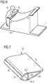
- FIGURE 6 shows a side perspective view on a mold 60 for performing the method of manufacturing the wind turbine blade 10 of FIGS. 4 and 5 according to an embodiment of the invention.
- the mold 60 comprises an insert 61 or in other words a protrusion.
- the insert 61 runs along a length of the shell 20 to be manufactured on the mold 60.
- a recess 24 as shown in FIG. 7 and corresponding to the insert 61 is provided in the shell 20 of the wind turbine blade 10.
- the mold 60 as shown may be used for manufacturing of a wind turbine blade 10 having a shell 20 of a butterfly configuration, in which two halves of the shell 20 are joined at the trailing edge TE and the leading edge LE.
- a further mold 60 having the insert 61 such that an integral shell 20 of a wind turbine blade 10 may be manufactured having a further recess 24 at its leading edge LE.
- the invention may be provided independently from the particular configuration or type of the shell 20.
- FIGURE 7 shows a side perspective view on a part of the wind turbine blade 10 as manufactured according to the method from FIG. 6 .
- the wind turbine blade 10 has the shell 20 and spar caps 30.1, 30.2 inside of the shell 20 connected to each other by means of a spar web 40.
- the shell 24 is provided with the recess 24.
- the protective cover 50 may be arranged or interlocked with the recess 24, such that a form-fitting is achieved and a flush transition 25 from the protective cover 50 to a paint coating 23 on the shell 20 may be achieved.
- the paint coating 23 may be provided before or after arranging the protective cover 50 in the recess 24.
- the recess 24 is wedge-shaped, in particular such that it is tapered from the leading edge LE towards the trailing edge TE.
Landscapes
- Engineering & Computer Science (AREA)
- Chemical & Material Sciences (AREA)
- Mechanical Engineering (AREA)
- Life Sciences & Earth Sciences (AREA)
- Sustainable Development (AREA)
- Sustainable Energy (AREA)
- Combustion & Propulsion (AREA)
- General Engineering & Computer Science (AREA)
- Composite Materials (AREA)
- Physics & Mathematics (AREA)
- Fluid Mechanics (AREA)
- Wind Motors (AREA)
Priority Applications (3)
| Application Number | Priority Date | Filing Date | Title |
|---|---|---|---|
| EP19209528.9A EP3822478A1 (de) | 2019-11-15 | 2019-11-15 | Verfahren zur herstellung einer schale einer windturbinenschaufel mit verbessertem vorderkantenerosionsschutz, verfahren zur herstellung der windturbinenschaufel, schale, windturbinenschaufel und windturbine |
| US17/083,656 US11371483B2 (en) | 2019-11-15 | 2020-10-29 | Method of manufacturing a shell of a wind turbine blade having improved leading edge erosion protection, method for manufacturing the wind turbine blade, shell, wind turbine blade and wind turbine |
| CN202011267169.5A CN112810186B (zh) | 2019-11-15 | 2020-11-13 | 制造风力涡轮机叶片及其壳体的方法、壳体、风力涡轮机叶片和风力涡轮机 |
Applications Claiming Priority (1)
| Application Number | Priority Date | Filing Date | Title |
|---|---|---|---|
| EP19209528.9A EP3822478A1 (de) | 2019-11-15 | 2019-11-15 | Verfahren zur herstellung einer schale einer windturbinenschaufel mit verbessertem vorderkantenerosionsschutz, verfahren zur herstellung der windturbinenschaufel, schale, windturbinenschaufel und windturbine |
Publications (1)
| Publication Number | Publication Date |
|---|---|
| EP3822478A1 true EP3822478A1 (de) | 2021-05-19 |
Family
ID=68583243
Family Applications (1)
| Application Number | Title | Priority Date | Filing Date |
|---|---|---|---|
| EP19209528.9A Pending EP3822478A1 (de) | 2019-11-15 | 2019-11-15 | Verfahren zur herstellung einer schale einer windturbinenschaufel mit verbessertem vorderkantenerosionsschutz, verfahren zur herstellung der windturbinenschaufel, schale, windturbinenschaufel und windturbine |
Country Status (3)
| Country | Link |
|---|---|
| US (1) | US11371483B2 (de) |
| EP (1) | EP3822478A1 (de) |
| CN (1) | CN112810186B (de) |
Cited By (1)
| Publication number | Priority date | Publication date | Assignee | Title |
|---|---|---|---|---|
| US11773824B2 (en) * | 2020-05-11 | 2023-10-03 | Siemens Gamesa Renewable Energy A/S | Method of manufacturing a wind turbine rotor blade |
Citations (9)
| Publication number | Priority date | Publication date | Assignee | Title |
|---|---|---|---|---|
| US20100008788A1 (en) * | 2008-07-14 | 2010-01-14 | Barbee Brent W | Protector for a leading edge of an airfoil |
| US20100278654A1 (en) * | 2009-05-01 | 2010-11-04 | General Electric Company | Wind turbine blade with prefabricated leading edge segments |
| US20110142678A1 (en) * | 2010-11-23 | 2011-06-16 | General Electric Company | Erosion protection coating for rotor blade of wind turbine |
| EP2338668A1 (de) * | 2009-12-22 | 2011-06-29 | Lm Glasfiber A/S | Verfahren zur Herstellung einer Verbundschalenstruktur |
| WO2013092211A1 (en) * | 2011-12-19 | 2013-06-27 | Lm Wind Power A/S | An erosion shield for a wind turbine blade |
| US20130189113A1 (en) * | 2012-01-20 | 2013-07-25 | Kristian Lehmann Madsen | Wind turbine rotor blade with trailing edge comprising rovings |
| US20160215757A1 (en) * | 2013-08-01 | 2016-07-28 | Blade Dynamics Limited | Erosion resistant aerodynamic fairing |
| WO2018206158A1 (en) * | 2017-05-09 | 2018-11-15 | Siemens Wind Power A/S | Lightning protection system for a wind turbine blade |
| WO2019048014A1 (en) * | 2017-09-06 | 2019-03-14 | Blade Repair Solutions Ivs | METHOD FOR REINFORCING A WIND TURBINE BLADE |
Family Cites Families (10)
| Publication number | Priority date | Publication date | Assignee | Title |
|---|---|---|---|---|
| US8961142B2 (en) * | 2009-04-10 | 2015-02-24 | Xemc Darwind B.V. | Protected wind turbine blade, a method of manufacturing it and a wind turbine |
| US8770942B2 (en) | 2011-01-26 | 2014-07-08 | Fujikura Rubber Ltd | Blade and laminated protective sheet for the blade |
| US20130045105A1 (en) * | 2011-08-17 | 2013-02-21 | Howard Daniel Driver | Wind turbine blade and method of protecting the same |
| US9709030B2 (en) * | 2013-12-16 | 2017-07-18 | General Electric Company | Methods of manufacturing rotor blade components for a wind turbine |
| EP2927482A1 (de) | 2014-04-01 | 2015-10-07 | LM WP Patent Holding A/S | Windturbinenschaufel mit Erosionsschild |
| JP2018503775A (ja) * | 2014-11-10 | 2018-02-08 | ポリテック エー/エス | ポリウレタン材料、かかる材料を作るための方法、及び風力タービン翼のための保護カバー |
| US11092133B2 (en) * | 2015-07-17 | 2021-08-17 | Lm Wp Patent Holding A/S | Wind turbine blade having an erosion shield |
| US10473086B2 (en) * | 2015-08-26 | 2019-11-12 | General Electric Company | Erosion resistant leading edge cap for a wind turbine rotor blade |
| ES2741277T5 (es) * | 2015-10-22 | 2024-02-22 | Wobben Properties Gmbh | Componente compuesto de varias capas |
| WO2019007471A1 (en) * | 2017-07-07 | 2019-01-10 | Vestas Wind Systems A/S | METHOD FOR COATING A ROTOR BLADE FOR A WIND TURBINE |
-
2019
- 2019-11-15 EP EP19209528.9A patent/EP3822478A1/de active Pending
-
2020
- 2020-10-29 US US17/083,656 patent/US11371483B2/en active Active
- 2020-11-13 CN CN202011267169.5A patent/CN112810186B/zh active Active
Patent Citations (9)
| Publication number | Priority date | Publication date | Assignee | Title |
|---|---|---|---|---|
| US20100008788A1 (en) * | 2008-07-14 | 2010-01-14 | Barbee Brent W | Protector for a leading edge of an airfoil |
| US20100278654A1 (en) * | 2009-05-01 | 2010-11-04 | General Electric Company | Wind turbine blade with prefabricated leading edge segments |
| EP2338668A1 (de) * | 2009-12-22 | 2011-06-29 | Lm Glasfiber A/S | Verfahren zur Herstellung einer Verbundschalenstruktur |
| US20110142678A1 (en) * | 2010-11-23 | 2011-06-16 | General Electric Company | Erosion protection coating for rotor blade of wind turbine |
| WO2013092211A1 (en) * | 2011-12-19 | 2013-06-27 | Lm Wind Power A/S | An erosion shield for a wind turbine blade |
| US20130189113A1 (en) * | 2012-01-20 | 2013-07-25 | Kristian Lehmann Madsen | Wind turbine rotor blade with trailing edge comprising rovings |
| US20160215757A1 (en) * | 2013-08-01 | 2016-07-28 | Blade Dynamics Limited | Erosion resistant aerodynamic fairing |
| WO2018206158A1 (en) * | 2017-05-09 | 2018-11-15 | Siemens Wind Power A/S | Lightning protection system for a wind turbine blade |
| WO2019048014A1 (en) * | 2017-09-06 | 2019-03-14 | Blade Repair Solutions Ivs | METHOD FOR REINFORCING A WIND TURBINE BLADE |
Cited By (1)
| Publication number | Priority date | Publication date | Assignee | Title |
|---|---|---|---|---|
| US11773824B2 (en) * | 2020-05-11 | 2023-10-03 | Siemens Gamesa Renewable Energy A/S | Method of manufacturing a wind turbine rotor blade |
Also Published As
| Publication number | Publication date |
|---|---|
| CN112810186B (zh) | 2023-10-03 |
| US11371483B2 (en) | 2022-06-28 |
| US20210148328A1 (en) | 2021-05-20 |
| CN112810186A (zh) | 2021-05-18 |
Similar Documents
| Publication | Publication Date | Title |
|---|---|---|
| US8191255B2 (en) | Method for manufacturing wind turbine blade with an integrated lightning conductor | |
| EP2927482A1 (de) | Windturbinenschaufel mit Erosionsschild | |
| US9403335B2 (en) | Wind turbine rotor blade with trailing edge comprising rovings | |
| US9677538B2 (en) | Wind turbine rotor blade assembly with root extension panel and method of assembly | |
| EP3551877B1 (de) | Windturbinenschaufel mit zwei schaufelteilen und einer aerodynamischen hülse | |
| EP4232707B1 (de) | Windturbinenrotorblatt mit einem vorderkantenelement | |
| WO2018206158A1 (en) | Lightning protection system for a wind turbine blade | |
| CA2737346A1 (en) | Method for manufacturing a wind turbine rotor blade and wind turbine rotor blade | |
| WO2019115372A1 (en) | A leading edge device, methods of manufacturing and in-stalling the leading edge device and a wind turbine blade | |
| EP4139116B1 (de) | Alternatives primer-applikationsverfahren | |
| KR20230065250A (ko) | 풍력 터빈 블레이드를 위한 리딩 에지 보호 | |
| CN106574602B (zh) | 加强的风力涡轮机叶片部件 | |
| EP3504429A1 (de) | Schutzabdecksystem | |
| US11371483B2 (en) | Method of manufacturing a shell of a wind turbine blade having improved leading edge erosion protection, method for manufacturing the wind turbine blade, shell, wind turbine blade and wind turbine | |
| EP3400133B1 (de) | Verfahren zum formen eines mantelteils einer windturbinenschaufel | |
| CN108883588B (zh) | 用于风轮机叶片的嵌入元件 | |
| EP4363711B1 (de) | Windturbinenschaufel | |
| EP4344866A1 (de) | Harzverbindungsteil für windturbinenschaufeln | |
| EP4357606A1 (de) | Verfahren zur herstellung von schutzelementen |
Legal Events
| Date | Code | Title | Description |
|---|---|---|---|
| PUAI | Public reference made under article 153(3) epc to a published international application that has entered the european phase |
Free format text: ORIGINAL CODE: 0009012 |
|
| STAA | Information on the status of an ep patent application or granted ep patent |
Free format text: STATUS: THE APPLICATION HAS BEEN PUBLISHED |
|
| AK | Designated contracting states |
Kind code of ref document: A1 Designated state(s): AL AT BE BG CH CY CZ DE DK EE ES FI FR GB GR HR HU IE IS IT LI LT LU LV MC MK MT NL NO PL PT RO RS SE SI SK SM TR |
|
| STAA | Information on the status of an ep patent application or granted ep patent |
Free format text: STATUS: REQUEST FOR EXAMINATION WAS MADE |
|
| 17P | Request for examination filed |
Effective date: 20211119 |
|
| RBV | Designated contracting states (corrected) |
Designated state(s): AL AT BE BG CH CY CZ DE DK EE ES FI FR GB GR HR HU IE IS IT LI LT LU LV MC MK MT NL NO PL PT RO RS SE SI SK SM TR |
|
| STAA | Information on the status of an ep patent application or granted ep patent |
Free format text: STATUS: EXAMINATION IS IN PROGRESS |
|
| 17Q | First examination report despatched |
Effective date: 20240202 |