EP3825973B1 - Brandmeldesystemsteuerung, brandmeldesystem, trennvorrichtung und verfahren zur initialisierung eines brandmeldesystems - Google Patents
Brandmeldesystemsteuerung, brandmeldesystem, trennvorrichtung und verfahren zur initialisierung eines brandmeldesystems Download PDFInfo
- Publication number
- EP3825973B1 EP3825973B1 EP19210896.7A EP19210896A EP3825973B1 EP 3825973 B1 EP3825973 B1 EP 3825973B1 EP 19210896 A EP19210896 A EP 19210896A EP 3825973 B1 EP3825973 B1 EP 3825973B1
- Authority
- EP
- European Patent Office
- Prior art keywords
- bus
- separator
- identifier information
- alarm system
- unique identifier
- Prior art date
- Legal status (The legal status is an assumption and is not a legal conclusion. Google has not performed a legal analysis and makes no representation as to the accuracy of the status listed.)
- Active
Links
Images


Classifications
-
- G—PHYSICS
- G08—SIGNALLING
- G08B—SIGNALLING SYSTEMS, e.g. PERSONAL CALLING SYSTEMS; ORDER TELEGRAPHS; ALARM SYSTEMS
- G08B25/00—Alarm systems in which the location of the alarm condition is signalled to a central station, e.g. fire or police telegraphic systems
- G08B25/003—Address allocation methods and details
-
- G—PHYSICS
- G08—SIGNALLING
- G08B—SIGNALLING SYSTEMS, e.g. PERSONAL CALLING SYSTEMS; ORDER TELEGRAPHS; ALARM SYSTEMS
- G08B17/00—Fire alarms; Alarms responsive to explosion
-
- G—PHYSICS
- G08—SIGNALLING
- G08B—SIGNALLING SYSTEMS, e.g. PERSONAL CALLING SYSTEMS; ORDER TELEGRAPHS; ALARM SYSTEMS
- G08B25/00—Alarm systems in which the location of the alarm condition is signalled to a central station, e.g. fire or police telegraphic systems
- G08B25/14—Central alarm receiver or annunciator arrangements
Definitions
- the present invention relates to an alarm system controller, an alarm system, a separator device and method for initializing an alarm system. Especially, the invention relates to a fire alarm system controller, a fire alarm system, a separator device and method for initializing a fire alarm system.
- EP 1703481 discloses a danger warning system that has a central station, i.e. control panel, and appliances, i.e. separator devices, which are connected thereto by a monitoring line of a bus.
- Each appliance has an insulator switch, a unique identifier information, and a communication address.
- the appliances that can be decoupled by the insulator switch are sequentially started and announced to the central station.
- the communication addresses are differed according to an arbitration method, and the two different communication addresses are sequentially registered.
- the central station has to wait a certain idle time, in order to make sure that no further appliance is trying to connect.
- DE 4 322 841 A discloses a danger-signalling installation, which operates using the chain-synchronising principle and whose detector is connected in a signal line which is constructed as a loop.
- the detectors are interrogated by a central station in alternate fashion from the two interrogation ends of the loop.
- the detectors On detection of a line fault as a result of a wire fracture or wire short-circuit in the loop, the detectors, positioned on both sides of the line fault, of the entire loop are interrogated within one and the same signalling cycle from the two interrogation ends.
- the document proposes to provide an additional switch and a resistor in each detector, which are used to short circuit the detector for an additional time during initialization and to monitor the current through the bus during this extra time.
- the system is configure to differentiate between the current flowing through 2 resistors connected in parallel and the current flowing when only 1 resistor is provided.
- an object of the invention to provide an alarm system controller, an alarm system, a separator device and method for initializing an alarm system which allow a faster initialisation process.
- a further advantage of the invention is to provide an alarm system controller, an alarm system, a separator device and method for initializing an alarm system which allow to recognize a unique identifier information error.
- the present invention provides an alarm system controller configured to be connected to a wired bus divided into a plurality of segments by means of a plurality of separator devices.
- the alarm system controller comprises a power module for supplying power to the bus to the separator devices, a communication module for performing a bidirectional digital communication through the bus with the separator devices, and a monitoring module for monitoring the electrical current supplied to the bus.
- the alarm system controller further includes an initialisation module for initialising the alarm system, wherein the initialisation module is configured to control the power module so as to temporarily increase an electrical voltage supplied through the bus above a first threshold, for triggering an internal initialization process of at least one of the plurality of separator modules, to control the monitoring module so as to determine whether more than one separator device has started the internal initialization process, depending upon whether the electrical current supplied to the bus exceeds a second threshold or not, and to control the communication module to perform an initialization communication with a separator device, which has started the internal initialization process, if only one separator devices has started the internal initialization process.
- the initialisation module is configured to perform an exception initialization process, if more than one separator device has started the internal initialization process.
- the alarm system controller of the present invention monitors, whether the current exceeds a second threshold, the alarm system controller can immediately recognize any branch in the bus, since a branch will lead to the simultaneous connection of at least two separator devices with a corresponding increased current, or whether only one separator device has been connected. If only one separator device has been connected, the alarm system controller of the invention does not have to wait for any further unique identifier information, and can immediately increase the voltage at the bus upon finalizing the internal initialization process of the one separator device. Thus, the overall time for the initialization of the system can be shorten.
- the communication module is configured to receive a unique identifier information from a separation device and to transmit an acknowledgement to the respective separation device including the received unique identifier information and a short identifier information.
- the initialisation module is configured to perform the exception initialization process including a bitwise arbitration process using the unique identifier information comprising receiving a first unique identifier information of a first separator device and transmitting an acknowledgement including the received first unique identifier information and a first short identifier information, subsequently receiving a second unique identifier information of a second separator device (5) and transmitting a response including the second received unique identifier information and a second short identifier information, and waiting to receive a further unique identifier information of a further separator device.
- the exception initialization process including a bitwise arbitration process using the unique identifier information comprising receiving a first unique identifier information of a first separator device and transmitting an acknowledgement including the received first unique identifier information and a first short identifier information, subsequently receiving a second unique identifier information of a second separator device (5) and transmitting a response including the second received unique identifier information and a second short identifier information, and waiting to receive a further unique identifie
- the initialisation module is configured to control the communication module so as to transmit the connection instruction to a first separator device and to postpone the transmission of the connection instruction to a second separator device.
- the alarm system controller further comprises a configuration storage module storing a table relating the unique identifier information and the first short identifier information of the respective separator devices with each other and further more storing relative position information of the separator devices along the bus.
- an alarm system comprising an alarm controller as discussed above, a bus and a plurality of separator devices.
- a separator device for an alarm system comprising an energy storage means for storing electrical energy, a separator control unit configured to control the operation and initialization of the separator device and charging and discharging of the energy storage means, an information storage means for storing the unique identifier information permanently and for storing the short identifier information in a rewriteable manner, and a separator communication module for transmitting the unique identifier information through the bus, while monitoring the bus for performing a bitwise arbitration process, wherein the separator control circuit is configured to detect the voltage at the bus and to perform the internal initialization process, when the detected voltage exceeds the first threshold level and no short identifier information is stored in the information storage means.
- a method for initializing an alarm system comprising the steps of:
- the exception initialization process comprises the steps of:
- the method further comprises the steps:
- the method further comprises: detecting that two separator devices, directly connected to a branching point of the bus, have identical unique identifier information, when an increased current is detected in step d) but no retransmission of a unique identifier information in step d3) is detected.
- the relation of unique identifier information and short identifier information is stored in the alarm system controller together with topographical information of the bus reflecting the relative position of the separator devices, branching points and segments.
- an alarm system especially a fire alarm system, comprises a control panel, a bus 3 and a plurality of alarm devices 5, like sensors or actuators.
- the bus 3 can be configured in a variety of topologies, including loops or stiches and even a combination of both.
- the bus 3, which is preferably a two wired bus, is used to supply power from the control panel to the alarm devices 5 and for a bidirectional transmission of digital information signals between the control panel 1 and the alarm devices 5.
- the alarm devices 5 are equipped with separator devices 5, which allow to isolate segments 15 of the bus 3 in in case of e.g. a short circuit or an earth fault.
- the control panel includes an alarm system controller 1, which is designed to perform an initialization process to acquire the topology of the alarm system and respective unique identifier information of all separator devices 5.
- control panel instructs this separator device 5 to connect the next segment 15 of the bus 3, that is the segment 15 of the bus 3 between this respective separator device 5 and an adjacent separator device 5.
- the control panel again increases the voltage, and the initializing process for the next separator device 5 is performed. This procedure is sequentially repeated until none of the separator devices 5 remain in the non-connected state.
- Each separator device 5 has the unique identifier information, like a MAC-Address, allowing a reliable identification.
- the separator device 5 transmits his unique identifier information to the control panel.
- the control panel acknowledges the receipt of the unique identifier information by retransmitting this unique identifier information together with a short identifier information to the separator device 5.
- the initialization process however is time consuming.
- the unique identifier information is lengthy, e.g. 64 Bit, and requires a certain time for the transmission and retransmission.
- the control panel assigns the short identifier information or communication address, e.g. 8 Bit, to the received unique identifier information and communicates this short identifier information together with the received unique identifier information to the separator device, so that in future communication the separator device 5 can be addressed using the short identifier information.
- the short identifier information has to be unique only within the bus controlled by the control panel.
- the bus 3 is not limited to a simple stich or a loop, it might occur that two or more separator devices 5, e.g. one in a stich and one in a loop, start the internal initialization processes simultaneously. In this case both separator devices 5 will start to transmit their unique identifier information simultaneously. To resolve this issue, a bitwise arbitration is carried out. That is, during the transmission both separator devices 5 monitor the bus 3 and compare the voltage level with their transmission signal. As soon as a bit of the unique identifier information of the two separator devices 5 differs, this will be recognized.
- a first separator device transmits a low level
- the bus will remain in the fixed low voltage level.
- the separator device 5 transmitting the low voltage level
- the other separator device 5 will stop the transmission of his unique identifier information and wait until the control panel has sent the acknowledgement including the unique identifier information and the short identifier information to the separator device 5, which has won the arbitration.
- the other separator device which has not won the arbitration, will restart the transmission of his unique identifier information to the control panel.
- the alarm system controller 1 of the invention comprises a power module 7, which is configured to supply power to the bus 3.
- the power module 7 is designed to operate at at least two different voltage levels, one for the usual operation of the alarm system, e.g. 12 V, and one for triggering the switching of a separator device 5 from the non-connected to the connected state, e.g. 40 V. These voltage values are only examples, and the invention is not limited thereto.
- the alarm system controller 1 includes a communication module 9 for enabling a bidirectional communication through the bus 3.
- the communication is performed through voltage modulation.
- the alarm system controller 1 additionally includes a monitoring module 11 which is arranged to monitor the current supplied to the bus 3.
- the energy storages 19 of more than one separator device 5 will draw current from the bus 3, while the power module is applying the high voltage level. Accordingly, the monitoring module 11 will recognize that the current supplied to the bus 3 exceeds the expected second threshold value. The detection of this event can be used to determine that more than one separator device 5 has tried to join the bus 3 and that accordingly, there is a branch in the bus 3. In other words, when the power module 7 applies a voltage at a first fixed predetermined level and if simultaneously the current monitored by the monitoring module 11 exceeds a second threshold, an initialization module 13 of the alarm system controller 1 will start an exception initialization process.
- the initialization module 13 will perform a regular initialization process in case the current does not exceed the above mentioned third threshold.
- the alarm system controller 1 further includes a configuration storage module 17, which will store a table relating the unique identifier information and the first short identifier information of the respective separator devices with each other and further more will store relative position information (topology information) of the separator devices 5 along the bus 3, indicating the sequence of separator devices 5 along the bus 3 and the respective branching points.
- a configuration storage module 17 which will store a table relating the unique identifier information and the first short identifier information of the respective separator devices with each other and further more will store relative position information (topology information) of the separator devices 5 along the bus 3, indicating the sequence of separator devices 5 along the bus 3 and the respective branching points.
- the alarm system controller 11 is equipped with respective switches S1 and S2.
- the alarm system controller 1 can alternatively perform the initialization from either side of the bus loop shown in Fig. 1 .
- the alarm system controller 1 can be designed to simultaneously perform the initialization from both sides of the bus loop, shown in Fig. 1 .
- the power module, the monitoring module and the communication module have to be designed to process the both sides of the bus simultaneously, for example by providing two power modules, two the monitoring modules and two communication modules or by adequately switching of these modules. This configuration has the advantage that the time for initialization is further decreased.
- Fig. 3 shows a separator device according to the invention.
- the separator device 5 comprises the energy storage means 19, e.g. a capacitor or a secondary battery.
- This energy storage means 19 is connected between the bus 3 and ground in parallel with a switch S5.
- the switch S5 is used to completely discharge the energy storage means 19, before beginning with the internal initialization process, in order to surely control the current, which will be drawn by the separator module 5.
- the energy storage means 19 can be used to supply power to the separator device 5 in case of a short interruption of power supply through the bus, or for reconnecting the separator device 5 after a short circuit event.
- the separator device 5 further includes a separator control unit 21 for controlling the operation and initialization of the separator device 5 and the charging and discharging of the energy storage means 19.
- an information storage means 23 for storing the unique identifier information permanently and for storing the short identifier information in a rewriteable manner.
- a separator communication module 25 transmits the unique identifier information through the bus 3, while monitoring the bus 3 for performing a bitwise arbitration process, as described above.
- the separator control circuit 21 detects the voltage at the bus 3 and performs the internal initialization process, when the detected voltage exceeds the first threshold level and no short identifier information is stored in the information storage means 23.
- the power module 9 of the alarm system controller 1 temporarily increases the voltage supplied from the power module 11 to a known voltage level, higher than the first threshold value.
- the separator control circuit 21 of a separator device 5 detects the increased voltage value, while charging the energy storage means 19 using the electrical power supplied through the bus 3, and performs the internal initialization process of the separator device 5.
- the monitoring module 9 of the alarm system controller detects the current flowing through the bus 3 controller.
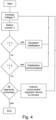
- the alarm system controller 1 concludes that more than one separator device 5 has started the internal initialization process, and performs an initialization communication with the separator device 5, which has started the internal initialization process, if only one separator devices 5 has started the internal initialization process and subsequently instructs the respective separator device 5 to connect next segment 15 of the bus 3. This concept is shown in the flow diagram of Fig. 4 .
- the separator device 5 is preferably equipped with two switches S3 and S4. At the beginning these switches S3 and S4 are open, so as to disconnect both sides of the bus 3. Upon receiving the high voltage level from the bus 3 and charging of the energy storage means 19, the switch S3 on the receiving side will be closed, so as to supply power to the internal circuit of the separator device 5, including the separator control unit 21, the information storage means 23 and the separator communication module 25.
- the power module 7 reduces the voltage at the bus 3 to the operation level and the transmission of digital information between the alarm system controller 1 and the separator device 5 is carried out.
- the separator device 5 When the separator device 5 is correctly initialized, that is, when the separator device 5 has transmitted his unique identifier information to the alarm system controller 1 and has received the acknowledgment of this information together with his short identifier information, the separator device 5 will close the other switch S4 and the alarm system controller 1 will raise the voltage at the bus 3 again to the high voltage level, unless an exception initialization process is required from the alarm system controller 1. Since the alarm system controller 1 does not need to wait an idle time to check, whether further separator devices 5 try to join the bus 3, the sequential connection of the separator devices 5 will proceed fast.
- the alarm system controller 1 Upon closing the second switch S4, the alarm system controller 1 applies the high voltage level to the next segment of the bus 3 and the initialization of the next separator device 5 is started.
- the alarm system controller 1 will postpone the instruction to the separator device 5 for connecting the next segment 15, i.e. to close the second switch S4. Furthermore, the alarm system controller 1 will continue to apply the low voltage level to the bus 3, so that a communication with other separator devices 5, which have not won the arbitration process, can be carried out.
- the initialization method of the alarm system includes transmitting from the separator devices 5 a unique identifier information while performing a bitwise arbitration and transmitting from the communication module of the alarm system controller 1 an acknowledgement including a short identifier information together with the unique identifier information of the separation device 5, which has succeeded in the bitwise arbitration of step.
- the method includes retransmitting only from the separator device or devices 5, which have not succeeded in the bitwise arbitration, the unique identifier information, while performing a bitwise arbitration
- the alarm system controller 1 will wait a predetermined idle time, after completion of the initialization of the second separator device 5, in order to give any third or fourth separation device 5, which had not won the arbitration so far, opportunity to transmit their unique identifier information, until all separator devices 5 have received their own short identifier information and no further access to the bus 3 is detected by the alarm system controller.
- the alarm system controller 5 continues to connect one separator device 5 after the other, until no further segment 15 of a stich of the bus is left unconnected or until the loop is closed.
- the alarm system controller 1 instructs through digital communication one of the separator devices 5, which have lost the arbitration, to close his second switch S4 and applies the high voltage level to the bus 3, again.
- the alarm system controller 1 will judge, whether all registered separator devices 5 have all their switches S3 and S4 closed, and that even when applying a high voltage, no current exceeding the usual operation current, which is lower than a third threshold, flows through the bus 3.
- the alarm system controller 1 of the present invention can recognize this situation, since a current exceeding the second threshold will flow into the bus. The alarm system controller can thus produce a warning, if after the detection of the high current only one separator device 5 requires to be connected.
- the invention can be used for fire alarm system, but it can be used for burglar alarm system or system for detecting toxic substances, like carbon monoxide.
- Both the separator modules 5 and the alarm system controller 1 comprise an information storage means 19 respectively a configuration storage module 17, which can be realized by means of respective EEPROMs or other known semiconductor memory devices.
- the separator device 5 is preferably equipped with two switches S3 and S4, it is basically possible to provide only one switch for isolating the segments of the bus 3 in each separator device 5.
Landscapes
- Business, Economics & Management (AREA)
- Emergency Management (AREA)
- Physics & Mathematics (AREA)
- General Physics & Mathematics (AREA)
- Alarm Systems (AREA)
- Small-Scale Networks (AREA)
Claims (12)
- Steuerung eines Alarmsystems, die konfiguriert ist, um mit einem verdrahteten Bus (3) verbunden zu sein, der in eine Mehrzahl von Segmenten (15) mittels einer Mehrzahl von Trennvorrichtungen (5) unterteilt ist, die jeweils ein Energiespeichermittel (19) umfassen, wobei die Steuerung des Alarmsystems Folgendes umfasst:ein Leistungsmodul (7) zum Zuführen von Leistung über den Bus (3) zu den Trennvorrichtungen (5);ein Kommunikationsmodul (9) zum Ausführen einer bidirektionalen digitalen Kommunikation über den Bus (3) mit den Trennvorrichtungen (5); undein Überwachungsmodul (11) zur Überwachung des über den Bus (3) zugeführten elektrischen Stroms, während die Energiespeichermittel (19) unter Verwendung der über den Bus zugeführten Leistung geladen werden;wobei die Steuerung eines Alarmsystems ferner umfasst:
ein Initialisierungsmodul (13) zum Initialisieren des Alarmsystems, wobei das Initialisierungsmodul (13) konfiguriert ist, um zu steuern:das Leistungsmodul (7), um eine über den Bus (3) zugeführte elektrische Spannung vorübergehend über einen ersten Schwellenwert auf das hohe Spannungsniveau zu erhöhen, um einen internen Initialisierungsvorgang von mindestens einem aus der Mehrzahl von Trennmodulen (5) auszulösen und die entsprechenden Energiespeichermittel (19) zu laden;das Überwachungsmodul (11), um zu bestimmen, ob mehr als eine Trennvorrichtung (5) den internen Initialisierungsvorgang gestartet hat, abhängig davon, ob der dem Bus (3) zugeführte elektrische Strom einen zweiten Schwellenwert überschreitet oder nicht; unddas Kommunikationsmodul (9), um eine Initialisierungs-Kommunikation mit einer Trennvorrichtung (5) auszuführen, die den internen Initialisierungsvorgang gestartet hat, wenn nur eine Trennvorrichtung (5) den internen Initialisierungsvorgang gestartet hat;wobei das Initialisierungsmodul (13) konfiguriert ist, um einen Ausnahme-Initialisierungsvorgang auszuführen, wenn das Überwachungsmodul (11) bestimmt hat, dass mehr als eine Trennvorrichtung (5) den internen Initialisierungsvorgang gestartet hat. - Die Steuerung eines Alarmsystems gemäß Anspruch 1, wobei
das Kommunikationsmodul (9) konfiguriert ist, um eine eindeutige Kennungsinformation von einer Trennvorrichtung (5) zu empfangen und eine Bestätigung an die jeweilige Trennvorrichtung (5) zu übertragen, die die empfangene eindeutige Kennungsinformation und eine Kurzkennungsinformation umfasst. - Die Steuerung eines Alarmsystems gemäß Anspruch 1 oder 2, wobei
das Initialisierungsmodul (13) konfiguriert ist, um den Initialisierungsvorgang für Ausnahmen auszuführen, der einen bitweisen Arbitrierungsprozess unter Verwendung der eindeutigen Kennungsinformation umfasst, umfassend:Empfangen einer ersten eindeutigen Kennungsinformation einer ersten Trennvorrichtung (5) und Übertragen einer Bestätigung, die die empfangene erste eindeutige Kennungsinformation und eine erste Kurzkennungsinformation umfasst;anschließend Empfangen einer zweiten eindeutigen Kennungsinformation einer zweiten Trennvorrichtung (5) und Übertragen einer Quittung, die die zweite empfangene eindeutige Kennungsinformation und eine zweite Kurzkennungsinformation umfasst; undWarten auf den Empfang einer weiteren eindeutigen Kennungsinformation einer weiteren Trennvorrichtung (5). - Die Steuerung eines Alarmsystems gemäß Anspruch 3, wobei
das Initialisierungsmodul (13) konfiguriert ist, um das Kommunikationsmodul (9) zu steuern, um eine Verbindungsanweisung an eine erste Trennvorrichtung (5) zu übertragen und die Übertragung der Verbindungsanweisung an eine zweite Trennvorrichtung (5) zu verschieben. - Die Steuerung eines Alarmsystems gemäß einem der Ansprüche 1 bis 4, ferner umfassend
ein Konfigurationsspeichermodul (17), das eine Tabelle speichert, die die eindeutigen Identifizierungsinformationen und die ersten Kurzkennungsinformationen der jeweiligen Trennvorrichtungen (5) voneinander betrifft, und das ferner Informationen über die relative Position der Trennvorrichtungen (5) entlang des Busses (3) speichert, wobei jede Trennvorrichtung ein Energiespeichermittel (19) umfasst. - Ein Alarmsystem, umfassend eine Alarmsteuerung gemäß einem der Ansprüche 1 bis 5, einen Bus (3) und eine Mehrzahl von Trennvorrichtungen (5).
- Eine Trennvorrichtung für ein Alarmsystem gemäß Anspruch 6, umfassend:ein Energiespeichermittel (19) zum Speichern elektrischer Energie;einen mit dem Energiespeichermittel (19) parallel zwischen Bus (3) und Erde verbundenen Switch (S5) zum vollständigen Austragen des Energiespeichermittels (19) vor Beginn des internen Initialisierungsvorgangs;eine Steuereinheit (21) der Trennvorrichtung, die konfiguriert ist, um den Betrieb und die Initialisierung der Trennvorrichtung (5) und das Laden und Austragen der Energiespeichermittel (19) zu steuern;
ein Informationsspeichermittel (23) zum dauerhaften Speichern der eindeutigen Identifizierungsinformation und zum Speichern der kurzen Identifizierungsinformation in einer wiederbeschreibbaren Weise; undein Trennerkommunikationsmodul (25) zum Übertragen der eindeutigen Identifizierungsinformationen über den Bus (3), während der Bus (3) überwacht wird, um einen bitweisen Arbitrierungsvorgang auszuführen;wobei die Trennersteuerschaltung (21) konfiguriert ist, um die Spannung am Bus (3) zu erfassen und den internen Initialisierungsvorgang auszuführen, der ein Laden der Energiespeichermittel (19) umfasst, wenn die erfasste Spannung den ersten Schwellenwert überschreitet und keine Kurzkennungsinformation in den Informationsspeichermitteln (23) gespeichert ist. - Ein Verfahren zur Initialisierung eines Alarmsystems gemäß Anspruch 6, das die folgenden Schritte umfasst:a) vorübergehendes Erhöhen der vom Leistungsmodul (11) zugeführten Spannung auf einen Wert, der höher als ein erster Schwellenwert ist, um die Energiespeichermittel (19) zu laden;b) Erfassen des erhöhten Spannungswerts durch mindestens eine Trennersteuerschaltung (21) einer Trennvorrichtung (5), während die Energiespeichermittel (19) unter Verwendung der über den Bus (3) zugeführten elektrischen Leistung geladen werden, und Ausführen eines internen Initialisierungsvorgangs der Trennvorrichtung (5);c) Erfassen eines Stroms, der zum Bus (3) strömt, während das Energiespeichermittel (19) unter Verwendung der über den Bus zugeführten elektrischen Leistung mittels des Überwachungsmoduls (11) der Steuerung eines Alarmsystems geladen wird;d) Bestimmen, wenn der erfasste Strom höher als der zweite Schwellenwert ist, dass mehr als eine Trennvorrichtung (5) den internen Initialisierungsvorgang gestartet hat; undAusführen einer Initialisierungs-Kommunikation mit einer Trennvorrichtung (5), die den internen Initialisierungsvorgang gestartet hat, wenn nur eine Trennvorrichtung (5) den internen Initialisierungsvorgang gestartet hat, und anschließendes Verbinden eines nächsten Segments (15) des Busses durch die Trennvorrichtung (5); oderAusführen eines Ausnahme-Initialisierungsvorgangs, wenn mehr als eine Trennvorrichtung (5) den internen Initialisierungsvorgang gestartet hat.
- Das Verfahren gemäß Anspruch 8, wobei der Initialisierungsvorgang für Ausnahmen die folgenden Schritte umfasstd1) Übertragen von eindeutigen Kennungsinformationen von den mehr als einer Trennvorrichtung (5), während eine bitweise Arbitrierung ausgeführt wird;d2) Übertragen einer Bestätigung von dem Kommunikationsmodul (9) der Steuerung eines Alarmsystems, die eine kurze Identifizierungsinformation zusammen mit der eindeutigen Identifizierungsinformation der Trennvorrichtung (5) umfasst, die bei der bitweisen Arbitrierung von Schritt d1) erfolgreich war;d3) erneutes Übertragen der eindeutigen Kennungsinformation nur von der Trennvorrichtung oder den Vorrichtungen (5), die bei der bitweisen Arbitrierung nicht erfolgreich waren, während eine bitweise Arbitrierung ausgeführt wird;d4) Übertragen einer Bestätigung von dem Kommunikationsmodul (9) der Steuerung eines Alarmsystems, die die Kurzkennungsinformation zusammen mit der eindeutigen Kennungsinformation der Trennvorrichtung (5) umfasst, die bei der bitweisen Arbitrierung von Schritt d3) erfolgreich war;d5) Ausführen der obigen Schritte d2) und d4), bis alle Trennvorrichtungen (5) der mehr als einen Trennvorrichtungen (5) eine Bestätigung empfangen haben, die eine Kurzkennungsinformation umfasst; undd6) Verbinden eines nächsten Segments (15) des Busses (3) durch die Trennvorrichtung (5), die bei der bitweisen Arbitrierung von Schritt d1) erfolgreich war.
- Das Verfahren gemäß Anspruch 8 oder 9, ferner umfassend die Schritte:e) Bestimmen, wenn der erfasste Strom höher als der dritte Schwellenwert, aber niedriger als der zweite Schwellenwert ist, dass eine Trennvorrichtung (5) den internen Initialisierungsvorgang gestartet hat;f) Wiederholen der Schritte a) bis e), bis das Überwachungsmodul (11) der Steuerung eines Alarmsystems (1) bestimmt, dass der Anstieg der Spannung in Schritt a) keinen Anstieg des zum Bus (3) fließenden Stroms verursacht, der den dritten Schwellenwert überschreitet, und Beurteilen, dass alle Trennvorrichtungen (5) eines jeweiligen Zweigs des Busses (3) initialisiert worden sind;g) Verbinden eines nächsten Segments (15) des Busses durch eine der Trennvorrichtungen (5), die bei einer bitweisen Arbitrierung in Schritt d1) oder d3) nicht erfolgreich waren;h) Wiederholen der Schritte a) bis e), bis das Überwachungsmodul (11) der Steuerung eines Alarmsystems (1) bestimmt, dass ein Anstieg der Spannung in Schritt a) keinen Anstieg des zum Bus (3) fließenden Stroms verursacht, der den dritten Schwellenwert überschreitet, und beurteilt, dass alle Trennvorrichtungen (5) eines jeweiligen Zweigs des Busses (3) initialisiert worden sind;i) Wiederholung der Schritte g) und h), bis alle Trennvorrichtungen (5) die jeweiligen Segmente des Busses (3) verbinden.
- Das Verfahren gemäß Anspruch 8, ferner umfassend:
Erfassen, dass zwei Trennvorrichtungen (5), die direkt mit einem Verzweigungspunkt des Busses (3) verbunden sind, identische eindeutige Identifizierungsinformationen haben, wenn ein erhöhter Strom in Schritt d) erfasst wird, aber keine erneute Übertragung einer eindeutigen Identifizierungsinformation in Schritt d3) erfasst wird. - Das Verfahren gemäß einem der Ansprüche 8 bis 11, wobei die Beziehung zwischen eindeutiger Kennungsinformation und kurzer Kennungsinformationen in der Steuerung eines Alarmsystems zusammen mit topographischen Informationen des Busses gespeichert wird, die die relative Position der Trennvorrichtungen (5), Verzweigungspunkte und Segmente (15) wiedergeben.
Priority Applications (1)
| Application Number | Priority Date | Filing Date | Title |
|---|---|---|---|
| EP19210896.7A EP3825973B1 (de) | 2019-11-22 | 2019-11-22 | Brandmeldesystemsteuerung, brandmeldesystem, trennvorrichtung und verfahren zur initialisierung eines brandmeldesystems |
Applications Claiming Priority (1)
| Application Number | Priority Date | Filing Date | Title |
|---|---|---|---|
| EP19210896.7A EP3825973B1 (de) | 2019-11-22 | 2019-11-22 | Brandmeldesystemsteuerung, brandmeldesystem, trennvorrichtung und verfahren zur initialisierung eines brandmeldesystems |
Publications (2)
| Publication Number | Publication Date |
|---|---|
| EP3825973A1 EP3825973A1 (de) | 2021-05-26 |
| EP3825973B1 true EP3825973B1 (de) | 2024-10-09 |
Family
ID=68655267
Family Applications (1)
| Application Number | Title | Priority Date | Filing Date |
|---|---|---|---|
| EP19210896.7A Active EP3825973B1 (de) | 2019-11-22 | 2019-11-22 | Brandmeldesystemsteuerung, brandmeldesystem, trennvorrichtung und verfahren zur initialisierung eines brandmeldesystems |
Country Status (1)
| Country | Link |
|---|---|
| EP (1) | EP3825973B1 (de) |
Families Citing this family (1)
| Publication number | Priority date | Publication date | Assignee | Title |
|---|---|---|---|---|
| CN118629182A (zh) * | 2024-06-11 | 2024-09-10 | 中船九江海洋装备(集团)有限公司 | 具有自动编址和成图的智能消防火警控制系统及控制方法 |
Family Cites Families (4)
| Publication number | Priority date | Publication date | Assignee | Title |
|---|---|---|---|---|
| DE4322841C2 (de) * | 1993-07-08 | 1996-02-15 | Zettler Gmbh | Gefahrenmeldeanlage |
| DE502005001967D1 (de) | 2005-03-15 | 2007-12-27 | Siemens Schweiz Ag | Verfahren zur Bestimmung der Konfiguration einer Gefahrenmeldeanlage und Gefahrenmeldeanlage |
| DE102010047227B3 (de) * | 2010-10-04 | 2012-03-01 | Hekatron Vertriebs Gmbh | Gefahrenmelder, Gefahrenmeldeanlage und Verfahren zum Erkennen von Leitungsfehlern |
| EP2833333B1 (de) * | 2013-07-31 | 2018-12-19 | Honeywell Life Safety Austria GmbH | Bus-System und Verfahren zum Betreiben eines Bus-Systems |
-
2019
- 2019-11-22 EP EP19210896.7A patent/EP3825973B1/de active Active
Also Published As
| Publication number | Publication date |
|---|---|
| EP3825973A1 (de) | 2021-05-26 |
Similar Documents
| Publication | Publication Date | Title |
|---|---|---|
| EP3408916B1 (de) | Automatische adressierung von batterieknoten in einem batteriesystem | |
| JP6831281B2 (ja) | 電池監視システムおよび電池監視装置 | |
| KR102501641B1 (ko) | 분산형 배터리 관리 시스템 및 관리 방법 | |
| EP3081427B1 (de) | Stromversorgungsvorrichtung eines fahrzeugs | |
| JP3973694B2 (ja) | スレーブ局、busシステム、およびbusシステムの駆動方法 | |
| RU2214000C2 (ru) | Способ и устройство для автоматического присвоения адресов извещателей в оповестительном аварийном устройстве | |
| US9007065B2 (en) | Battery monitoring apparatus | |
| US4347602A (en) | Circuit arrangement for time division multiplex data transmission with a bus system | |
| JP5561239B2 (ja) | 自動付番装置 | |
| KR20110058663A (ko) | 리모트 배선 체크 시스템 및 그 시스템에 사용하는 접속 커넥터 | |
| US12574683B2 (en) | Device for electronically connecting and disconnecting portions of an electrical line, public address system, method for detecting a failure in an electrical line | |
| KR101926195B1 (ko) | 병렬 팩 배터리 시스템의 릴레이 융착 관리 장치 및 그 방법 | |
| WO2007029673A1 (ja) | 蓄電機器状態検出装置 | |
| US9153972B2 (en) | Battery monitoring apparatus | |
| EP3825973B1 (de) | Brandmeldesystemsteuerung, brandmeldesystem, trennvorrichtung und verfahren zur initialisierung eines brandmeldesystems | |
| KR20150003545A (ko) | 자동 파워릴레이어셈블리를 포함하는 배터리 시스템 및 그 동작방법 | |
| EP2833333B1 (de) | Bus-System und Verfahren zum Betreiben eines Bus-Systems | |
| CN112462163A (zh) | 一种高压互锁回路故障检测方法及装置 | |
| EP3951736B1 (de) | Verfahren und vorrichtung zur signalübertragung von drahtgebundenen sicherheitssensoren und/oder brandmeldern | |
| JP2766766B2 (ja) | 防災監視装置 | |
| KR102501640B1 (ko) | 분산형 배터리 관리 시스템 및 관리 방법 | |
| JP7515569B2 (ja) | 電池監視装置 | |
| JP2020022332A (ja) | 車載充電装置 | |
| JP2020123182A (ja) | 火災報知設備 | |
| CN121172939A (zh) | 光伏系统及其控制器、安全控制方法 |
Legal Events
| Date | Code | Title | Description |
|---|---|---|---|
| PUAI | Public reference made under article 153(3) epc to a published international application that has entered the european phase |
Free format text: ORIGINAL CODE: 0009012 |
|
| STAA | Information on the status of an ep patent application or granted ep patent |
Free format text: STATUS: THE APPLICATION HAS BEEN PUBLISHED |
|
| AK | Designated contracting states |
Kind code of ref document: A1 Designated state(s): AL AT BE BG CH CY CZ DE DK EE ES FI FR GB GR HR HU IE IS IT LI LT LU LV MC MK MT NL NO PL PT RO RS SE SI SK SM TR |
|
| STAA | Information on the status of an ep patent application or granted ep patent |
Free format text: STATUS: REQUEST FOR EXAMINATION WAS MADE |
|
| 17P | Request for examination filed |
Effective date: 20211124 |
|
| RBV | Designated contracting states (corrected) |
Designated state(s): AL AT BE BG CH CY CZ DE DK EE ES FI FR GB GR HR HU IE IS IT LI LT LU LV MC MK MT NL NO PL PT RO RS SE SI SK SM TR |
|
| STAA | Information on the status of an ep patent application or granted ep patent |
Free format text: STATUS: EXAMINATION IS IN PROGRESS |
|
| 17Q | First examination report despatched |
Effective date: 20230201 |
|
| P01 | Opt-out of the competence of the unified patent court (upc) registered |
Effective date: 20230523 |
|
| GRAP | Despatch of communication of intention to grant a patent |
Free format text: ORIGINAL CODE: EPIDOSNIGR1 |
|
| STAA | Information on the status of an ep patent application or granted ep patent |
Free format text: STATUS: GRANT OF PATENT IS INTENDED |
|
| INTG | Intention to grant announced |
Effective date: 20240507 |
|
| GRAS | Grant fee paid |
Free format text: ORIGINAL CODE: EPIDOSNIGR3 |
|
| GRAA | (expected) grant |
Free format text: ORIGINAL CODE: 0009210 |
|
| STAA | Information on the status of an ep patent application or granted ep patent |
Free format text: STATUS: THE PATENT HAS BEEN GRANTED |
|
| AK | Designated contracting states |
Kind code of ref document: B1 Designated state(s): AL AT BE BG CH CY CZ DE DK EE ES FI FR GB GR HR HU IE IS IT LI LT LU LV MC MK MT NL NO PL PT RO RS SE SI SK SM TR |
|
| REG | Reference to a national code |
Ref country code: CH Ref legal event code: EP |
|
| REG | Reference to a national code |
Ref country code: DE Ref legal event code: R096 Ref document number: 602019059975 Country of ref document: DE |
|
| REG | Reference to a national code |
Ref country code: IE Ref legal event code: FG4D |
|
| REG | Reference to a national code |
Ref country code: LT Ref legal event code: MG9D |
|
| REG | Reference to a national code |
Ref country code: NL Ref legal event code: MP Effective date: 20241009 |
|
| REG | Reference to a national code |
Ref country code: AT Ref legal event code: MK05 Ref document number: 1731446 Country of ref document: AT Kind code of ref document: T Effective date: 20241009 |
|
| PG25 | Lapsed in a contracting state [announced via postgrant information from national office to epo] |
Ref country code: NL Free format text: LAPSE BECAUSE OF FAILURE TO SUBMIT A TRANSLATION OF THE DESCRIPTION OR TO PAY THE FEE WITHIN THE PRESCRIBED TIME-LIMIT Effective date: 20241009 |
|
| PG25 | Lapsed in a contracting state [announced via postgrant information from national office to epo] |
Ref country code: NL Free format text: LAPSE BECAUSE OF FAILURE TO SUBMIT A TRANSLATION OF THE DESCRIPTION OR TO PAY THE FEE WITHIN THE PRESCRIBED TIME-LIMIT Effective date: 20241009 |
|
| PG25 | Lapsed in a contracting state [announced via postgrant information from national office to epo] |
Ref country code: HR Free format text: LAPSE BECAUSE OF FAILURE TO SUBMIT A TRANSLATION OF THE DESCRIPTION OR TO PAY THE FEE WITHIN THE PRESCRIBED TIME-LIMIT Effective date: 20241009 Ref country code: IS Free format text: LAPSE BECAUSE OF FAILURE TO SUBMIT A TRANSLATION OF THE DESCRIPTION OR TO PAY THE FEE WITHIN THE PRESCRIBED TIME-LIMIT Effective date: 20250209 Ref country code: PT Free format text: LAPSE BECAUSE OF FAILURE TO SUBMIT A TRANSLATION OF THE DESCRIPTION OR TO PAY THE FEE WITHIN THE PRESCRIBED TIME-LIMIT Effective date: 20250210 |
|
| PG25 | Lapsed in a contracting state [announced via postgrant information from national office to epo] |
Ref country code: FI Free format text: LAPSE BECAUSE OF FAILURE TO SUBMIT A TRANSLATION OF THE DESCRIPTION OR TO PAY THE FEE WITHIN THE PRESCRIBED TIME-LIMIT Effective date: 20241009 |
|
| PG25 | Lapsed in a contracting state [announced via postgrant information from national office to epo] |
Ref country code: BG Free format text: LAPSE BECAUSE OF FAILURE TO SUBMIT A TRANSLATION OF THE DESCRIPTION OR TO PAY THE FEE WITHIN THE PRESCRIBED TIME-LIMIT Effective date: 20241009 |
|
| PG25 | Lapsed in a contracting state [announced via postgrant information from national office to epo] |
Ref country code: ES Free format text: LAPSE BECAUSE OF FAILURE TO SUBMIT A TRANSLATION OF THE DESCRIPTION OR TO PAY THE FEE WITHIN THE PRESCRIBED TIME-LIMIT Effective date: 20241009 |
|
| PG25 | Lapsed in a contracting state [announced via postgrant information from national office to epo] |
Ref country code: NO Free format text: LAPSE BECAUSE OF FAILURE TO SUBMIT A TRANSLATION OF THE DESCRIPTION OR TO PAY THE FEE WITHIN THE PRESCRIBED TIME-LIMIT Effective date: 20250109 |
|
| PG25 | Lapsed in a contracting state [announced via postgrant information from national office to epo] |
Ref country code: AT Free format text: LAPSE BECAUSE OF FAILURE TO SUBMIT A TRANSLATION OF THE DESCRIPTION OR TO PAY THE FEE WITHIN THE PRESCRIBED TIME-LIMIT Effective date: 20241009 Ref country code: LV Free format text: LAPSE BECAUSE OF FAILURE TO SUBMIT A TRANSLATION OF THE DESCRIPTION OR TO PAY THE FEE WITHIN THE PRESCRIBED TIME-LIMIT Effective date: 20241009 Ref country code: GR Free format text: LAPSE BECAUSE OF FAILURE TO SUBMIT A TRANSLATION OF THE DESCRIPTION OR TO PAY THE FEE WITHIN THE PRESCRIBED TIME-LIMIT Effective date: 20250110 |
|
| PG25 | Lapsed in a contracting state [announced via postgrant information from national office to epo] |
Ref country code: PL Free format text: LAPSE BECAUSE OF FAILURE TO SUBMIT A TRANSLATION OF THE DESCRIPTION OR TO PAY THE FEE WITHIN THE PRESCRIBED TIME-LIMIT Effective date: 20241009 |
|
| PG25 | Lapsed in a contracting state [announced via postgrant information from national office to epo] |
Ref country code: RS Free format text: LAPSE BECAUSE OF FAILURE TO SUBMIT A TRANSLATION OF THE DESCRIPTION OR TO PAY THE FEE WITHIN THE PRESCRIBED TIME-LIMIT Effective date: 20250109 |
|
| REG | Reference to a national code |
Ref country code: CH Ref legal event code: PL |
|
| PG25 | Lapsed in a contracting state [announced via postgrant information from national office to epo] |
Ref country code: SM Free format text: LAPSE BECAUSE OF FAILURE TO SUBMIT A TRANSLATION OF THE DESCRIPTION OR TO PAY THE FEE WITHIN THE PRESCRIBED TIME-LIMIT Effective date: 20241009 |
|
| PG25 | Lapsed in a contracting state [announced via postgrant information from national office to epo] |
Ref country code: MC Free format text: LAPSE BECAUSE OF FAILURE TO SUBMIT A TRANSLATION OF THE DESCRIPTION OR TO PAY THE FEE WITHIN THE PRESCRIBED TIME-LIMIT Effective date: 20241009 |
|
| PG25 | Lapsed in a contracting state [announced via postgrant information from national office to epo] |
Ref country code: DK Free format text: LAPSE BECAUSE OF FAILURE TO SUBMIT A TRANSLATION OF THE DESCRIPTION OR TO PAY THE FEE WITHIN THE PRESCRIBED TIME-LIMIT Effective date: 20241009 |
|
| REG | Reference to a national code |
Ref country code: DE Ref legal event code: R097 Ref document number: 602019059975 Country of ref document: DE |
|
| PG25 | Lapsed in a contracting state [announced via postgrant information from national office to epo] |
Ref country code: LU Free format text: LAPSE BECAUSE OF NON-PAYMENT OF DUE FEES Effective date: 20241122 |
|
| REG | Reference to a national code |
Ref country code: CH Ref legal event code: PL |
|
| PG25 | Lapsed in a contracting state [announced via postgrant information from national office to epo] |
Ref country code: EE Free format text: LAPSE BECAUSE OF FAILURE TO SUBMIT A TRANSLATION OF THE DESCRIPTION OR TO PAY THE FEE WITHIN THE PRESCRIBED TIME-LIMIT Effective date: 20241009 |
|
| PG25 | Lapsed in a contracting state [announced via postgrant information from national office to epo] |
Ref country code: CH Free format text: LAPSE BECAUSE OF NON-PAYMENT OF DUE FEES Effective date: 20241130 |
|
| PG25 | Lapsed in a contracting state [announced via postgrant information from national office to epo] |
Ref country code: RO Free format text: LAPSE BECAUSE OF FAILURE TO SUBMIT A TRANSLATION OF THE DESCRIPTION OR TO PAY THE FEE WITHIN THE PRESCRIBED TIME-LIMIT Effective date: 20241009 |
|
| PG25 | Lapsed in a contracting state [announced via postgrant information from national office to epo] |
Ref country code: SK Free format text: LAPSE BECAUSE OF FAILURE TO SUBMIT A TRANSLATION OF THE DESCRIPTION OR TO PAY THE FEE WITHIN THE PRESCRIBED TIME-LIMIT Effective date: 20241009 |
|
| PG25 | Lapsed in a contracting state [announced via postgrant information from national office to epo] |
Ref country code: CZ Free format text: LAPSE BECAUSE OF FAILURE TO SUBMIT A TRANSLATION OF THE DESCRIPTION OR TO PAY THE FEE WITHIN THE PRESCRIBED TIME-LIMIT Effective date: 20241009 |
|
| PG25 | Lapsed in a contracting state [announced via postgrant information from national office to epo] |
Ref country code: IT Free format text: LAPSE BECAUSE OF FAILURE TO SUBMIT A TRANSLATION OF THE DESCRIPTION OR TO PAY THE FEE WITHIN THE PRESCRIBED TIME-LIMIT Effective date: 20241009 |
|
| PLBE | No opposition filed within time limit |
Free format text: ORIGINAL CODE: 0009261 |
|
| STAA | Information on the status of an ep patent application or granted ep patent |
Free format text: STATUS: NO OPPOSITION FILED WITHIN TIME LIMIT |
|
| REG | Reference to a national code |
Ref country code: BE Ref legal event code: MM Effective date: 20241130 |
|
| PG25 | Lapsed in a contracting state [announced via postgrant information from national office to epo] |
Ref country code: SE Free format text: LAPSE BECAUSE OF FAILURE TO SUBMIT A TRANSLATION OF THE DESCRIPTION OR TO PAY THE FEE WITHIN THE PRESCRIBED TIME-LIMIT Effective date: 20241009 |
|
| 26N | No opposition filed |
Effective date: 20250710 |
|
| PG25 | Lapsed in a contracting state [announced via postgrant information from national office to epo] |
Ref country code: BE Free format text: LAPSE BECAUSE OF NON-PAYMENT OF DUE FEES Effective date: 20241130 |
|
| PG25 | Lapsed in a contracting state [announced via postgrant information from national office to epo] |
Ref country code: IE Free format text: LAPSE BECAUSE OF NON-PAYMENT OF DUE FEES Effective date: 20241122 |
|
| PGFP | Annual fee paid to national office [announced via postgrant information from national office to epo] |
Ref country code: DE Payment date: 20251126 Year of fee payment: 7 |
|
| PGFP | Annual fee paid to national office [announced via postgrant information from national office to epo] |
Ref country code: GB Payment date: 20251125 Year of fee payment: 7 |
|
| PGFP | Annual fee paid to national office [announced via postgrant information from national office to epo] |
Ref country code: FR Payment date: 20251125 Year of fee payment: 7 |
|
| PG25 | Lapsed in a contracting state [announced via postgrant information from national office to epo] |
Ref country code: HU Free format text: LAPSE BECAUSE OF FAILURE TO SUBMIT A TRANSLATION OF THE DESCRIPTION OR TO PAY THE FEE WITHIN THE PRESCRIBED TIME-LIMIT; INVALID AB INITIO Effective date: 20191122 |
|
| PG25 | Lapsed in a contracting state [announced via postgrant information from national office to epo] |
Ref country code: CY Free format text: LAPSE BECAUSE OF FAILURE TO SUBMIT A TRANSLATION OF THE DESCRIPTION OR TO PAY THE FEE WITHIN THE PRESCRIBED TIME-LIMIT; INVALID AB INITIO Effective date: 20191122 |