EP3829757B1 - Statische mischvorrichtung und verfahren zum mischen von phosgen und einem organischen amin - Google Patents
Statische mischvorrichtung und verfahren zum mischen von phosgen und einem organischen amin Download PDFInfo
- Publication number
- EP3829757B1 EP3829757B1 EP19745439.0A EP19745439A EP3829757B1 EP 3829757 B1 EP3829757 B1 EP 3829757B1 EP 19745439 A EP19745439 A EP 19745439A EP 3829757 B1 EP3829757 B1 EP 3829757B1
- Authority
- EP
- European Patent Office
- Prior art keywords
- conduit
- cross
- jets
- sectional area
- phosgene
- Prior art date
- Legal status (The legal status is an assumption and is not a legal conclusion. Google has not performed a legal analysis and makes no representation as to the accuracy of the status listed.)
- Active
Links
Images

Classifications
-
- B—PERFORMING OPERATIONS; TRANSPORTING
- B01—PHYSICAL OR CHEMICAL PROCESSES OR APPARATUS IN GENERAL
- B01F—MIXING, e.g. DISSOLVING, EMULSIFYING OR DISPERSING
- B01F25/00—Flow mixers; Mixers for falling materials, e.g. solid particles
- B01F25/30—Injector mixers
- B01F25/31—Injector mixers in conduits or tubes through which the main component flows
- B01F25/314—Injector mixers in conduits or tubes through which the main component flows wherein additional components are introduced at the circumference of the conduit
- B01F25/3141—Injector mixers in conduits or tubes through which the main component flows wherein additional components are introduced at the circumference of the conduit with additional mixing means other than injector mixers
-
- B—PERFORMING OPERATIONS; TRANSPORTING
- B01—PHYSICAL OR CHEMICAL PROCESSES OR APPARATUS IN GENERAL
- B01F—MIXING, e.g. DISSOLVING, EMULSIFYING OR DISPERSING
- B01F25/00—Flow mixers; Mixers for falling materials, e.g. solid particles
- B01F25/30—Injector mixers
- B01F25/31—Injector mixers in conduits or tubes through which the main component flows
- B01F25/314—Injector mixers in conduits or tubes through which the main component flows wherein additional components are introduced at the circumference of the conduit
- B01F25/3142—Injector mixers in conduits or tubes through which the main component flows wherein additional components are introduced at the circumference of the conduit the conduit having a plurality of openings in the axial direction or in the circumferential direction
- B01F25/31423—Injector mixers in conduits or tubes through which the main component flows wherein additional components are introduced at the circumference of the conduit the conduit having a plurality of openings in the axial direction or in the circumferential direction with a plurality of perforations in the circumferential direction only and covering the whole circumference
-
- C—CHEMISTRY; METALLURGY
- C07—ORGANIC CHEMISTRY
- C07C—ACYCLIC OR CARBOCYCLIC COMPOUNDS
- C07C263/00—Preparation of derivatives of isocyanic acid
- C07C263/10—Preparation of derivatives of isocyanic acid by reaction of amines with carbonyl halides, e.g. with phosgene
-
- B—PERFORMING OPERATIONS; TRANSPORTING
- B01—PHYSICAL OR CHEMICAL PROCESSES OR APPARATUS IN GENERAL
- B01F—MIXING, e.g. DISSOLVING, EMULSIFYING OR DISPERSING
- B01F25/00—Flow mixers; Mixers for falling materials, e.g. solid particles
- B01F25/30—Injector mixers
- B01F25/31—Injector mixers in conduits or tubes through which the main component flows
- B01F25/314—Injector mixers in conduits or tubes through which the main component flows wherein additional components are introduced at the circumference of the conduit
- B01F25/3143—Injector mixers in conduits or tubes through which the main component flows wherein additional components are introduced at the circumference of the conduit characterised by the specific design of the injector
-
- B—PERFORMING OPERATIONS; TRANSPORTING
- B01—PHYSICAL OR CHEMICAL PROCESSES OR APPARATUS IN GENERAL
- B01F—MIXING, e.g. DISSOLVING, EMULSIFYING OR DISPERSING
- B01F25/00—Flow mixers; Mixers for falling materials, e.g. solid particles
- B01F25/30—Injector mixers
- B01F25/31—Injector mixers in conduits or tubes through which the main component flows
- B01F25/315—Injector mixers in conduits or tubes through which the main component flows wherein a difference of pressure at different points of the conduit causes introduction of the additional component into the main component
-
- B—PERFORMING OPERATIONS; TRANSPORTING
- B01—PHYSICAL OR CHEMICAL PROCESSES OR APPARATUS IN GENERAL
- B01F—MIXING, e.g. DISSOLVING, EMULSIFYING OR DISPERSING
- B01F25/00—Flow mixers; Mixers for falling materials, e.g. solid particles
- B01F25/40—Static mixers
- B01F25/42—Static mixers in which the mixing is affected by moving the components jointly in changing directions, e.g. in tubes provided with baffles or obstructions
- B01F25/43—Mixing tubes, e.g. wherein the material is moved in a radial or partly reversed direction
- B01F25/433—Mixing tubes wherein the shape of the tube influences the mixing, e.g. mixing tubes with varying cross-section or provided with inwardly extending profiles
- B01F25/4336—Mixers with a diverging cross-section
-
- B—PERFORMING OPERATIONS; TRANSPORTING
- B01—PHYSICAL OR CHEMICAL PROCESSES OR APPARATUS IN GENERAL
- B01J—CHEMICAL OR PHYSICAL PROCESSES, e.g. CATALYSIS OR COLLOID CHEMISTRY; THEIR RELEVANT APPARATUS
- B01J19/00—Chemical, physical or physico-chemical processes in general; Their relevant apparatus
- B01J19/24—Stationary reactors without moving elements inside
- B01J19/2405—Stationary reactors without moving elements inside provoking a turbulent flow of the reactants, such as in cyclones, or having a high Reynolds-number
-
- B—PERFORMING OPERATIONS; TRANSPORTING
- B01—PHYSICAL OR CHEMICAL PROCESSES OR APPARATUS IN GENERAL
- B01J—CHEMICAL OR PHYSICAL PROCESSES, e.g. CATALYSIS OR COLLOID CHEMISTRY; THEIR RELEVANT APPARATUS
- B01J19/00—Chemical, physical or physico-chemical processes in general; Their relevant apparatus
- B01J19/26—Nozzle-type reactors, i.e. the distribution of the initial reactants within the reactor is effected by their introduction or injection through nozzles
-
- B—PERFORMING OPERATIONS; TRANSPORTING
- B01—PHYSICAL OR CHEMICAL PROCESSES OR APPARATUS IN GENERAL
- B01F—MIXING, e.g. DISSOLVING, EMULSIFYING OR DISPERSING
- B01F2101/00—Mixing characterised by the nature of the mixed materials or by the application field
- B01F2101/2204—Mixing chemical components in generals in order to improve chemical treatment or reactions, independently from the specific application
Definitions
- the present invention relates to a method for mixing phosgene with an organic amine and to a static mixing device useful in the method.
- Polyisocyanates are made industrially by the reaction of phosgene with polyamine compounds.
- the organic polyamine typically is injected continuously into a flowing phosgene stream.
- the phosgene is usually in excess.
- the reaction is fast and highly exothermic and produces HCl as a by-product. Rapid and thorough mixing is needed to take advantage of consuming the polyamine in certain fast reactions.
- This process is susceptible to the formation of unwanted by-products.
- unwanted by-products can include, for example, various urea, carbodiimide, uretonimine and other materials. These often form at least partially as a result of incomplete mixing of the organic polyamine and the phosgene. They often form in very low concentration but build up over time and foul process equipment.
- US2010/137634A1 and US2010/305356A1 also disclose a method and a device for mixing phosgene.
- the phosgenation mixer in US Published Patent Application No. 2011-0230679 describes the use of a "guide element" that is disposed with the mixer body.
- the guide element occupies the center of an otherwise tubular conduit, converting a circular phosgene flow path into an annular one as the phosgene passes by the guide element.
- the organic polyamine is introduced through multiple jets that are located in the section where the annular phosgene flow path exists. This promotes high mixer performance. Despite the improvements offered by this mixer design, it is desirable to reduce by-product formation even more.
- This invention is in one aspect a method for mixing phosgene with an organic polyamine comprising;
- the invention is also a static mixing device comprising:
- phosgenation mixer 1 includes outer sidewall 2 and central insert 3, which together define conduit 15 through which an axially directed flow of phosgene is established, upstream of jets 6, in the direction indicated by arrow 5 ( Figure 3 ).
- a plurality of circumferentially-aligned jets 6 penetrate outer sidewall 2, each jet 6 forming a flow path for injecting an organic polyamine stream from the outside of outer sidewall 2 into conduit 15.
- Supports 16 hold central insert 3 in place within phosgenation mixer 1.
- Central insert 3 preferably is centrally aligned along the central axis of phosgenation mixer 1 such that the width of conduit 15 is constant at all points on any plane perpendicular to axial direction 5.
- Projection 9 creates a constricted region 4 (see Figure 3 ) within conduit 15.
- Cross-sectional area A may be, for example, from 0.25 cm 2 to 120 cm 2 .
- Jets 6 have a hydrodynamic diameter indicated by D j in Figure 3 .
- the diameter is considered as the diameter of a circle have the same cross-sectional area of each jet 6.
- the diameter is that at the outlet of jets 6, i.e., at the point from which the organic polyamine is discharged into conduit 15. Jets 6 may not have a constant diameter along their length. In some embodiments, jets 6 are tapered, having a smallest diameter at their outlet.
- the jet diameter D j may be, for example, at least 2 mm, at least 3 mm or at least 4 mm and may be, for example, up to 20 mm, up to 10 mm, up to 8 mm or up to 6 mm.
- Constricted region 4 is defined as that portion of conduit 15, downstream of jets 6, having a cross-sectional area less than the cross-sectional area A of conduit 15.
- constricted region 4 begins at line 7, where projection 9 protrudes into conduit 15 and narrows it.
- Constricted region 4 in the embodiment shown in Figure 3 reaches a minimum cross-sectional area at line 14.
- Constricted region 4 ends at line 8, where the cross-sectional area of conduit 15 again becomes equal to A.
- Region 13 may form part of conduit 15 as shown in Figures 1-3 , or may be or include another space in fluid communication with the outlet end of conduit 15.
- the start of constricted region 4 (indicated as line 7 of Figure 3 ) is between 0.01 and 3 jet diameters downstream of jets 6. This distance (indicated as Di in Figure 3 ) is measured from the downstream edge of jets 6, which in Figure 3 is indicated by line 12. In Figure 3 , this distance is approximately 0.25 jet diameters downstream of jets 6.
- Downstream for purposes of this invention indicates the direction of mass flow through conduit 15, which in Figures 1-3 is toward the right.
- Upstream refers to the opposite direction, which in Figures 1-3 is toward the left.
- the end of constricted region 4 (indicated as line 8 of Figure 3 ) is no more than 50 jet diameters downstream of jets 6. This distance (indicated as D 2 in Figure 3 ) is measured from the downstream edge of jets 6, which in Figure 3 is indicated by line 12.
- the end of constricted region 4 may be no more than 25, no more than 20, no more than 18, no more than 15, no more than 12, no more than 10 or no more than 8 jet diameters downstream of jets 6. In Figure 3 , the end of constricted region 4 is approximately 4 jet diameters downstream of jets 6.
- the cross-sectional area of constricted region 4 may not be constant along its length.
- the cross-sectional area of constriction region 4 reaches a minimum at line 14.
- the smallest cross-sectional area of constricted region 4 is at least 50% of cross-sectional area A and at most 85% of cross-sectional area A. It may be up to 75% of cross-sectional area A.
- the point at which the cross-sectional area of constricted region 4 first reaches its minimum is preferably 0.5 to 5, especially 1 to 3 jet diameters downstream from jets 6.
- Figures 1-3 illustrate the method and the device according to the present invention in which the constricted region is produced by an circumferential projection 9 located on an internal surface of the outer sidewall 2 of conduit 15, perpendicular to the axially directed phosgene flow 5. It is possible, however, to produce the constriction by placing such an annular projection on the surface of insert 3 ( i.e., the inner sidewall of an annular conduit of the type illustrated in Figures 1-3 ), or on both the inner and outer sidewalls of conduit 15).
- annular projection 9 has a curved leading edge 11.
- the "leading edge" of the circumferential projection it that disposed toward the upstream end of conduit 15, i.e., facing the oncoming phosgene/organic amine flow.
- the organic polyamine injected into conduit 15 at each of jets 6 forms an organic polyamine stream. Because phosgene is simultaneously flowing through conduit 15, its momentum causes the organic polyamine stream to bend in a downstream direction, producing a curved flow path such as is indicated by reference numeral 10 of Figure 3 .
- the constricted region 4 is formed by an circumferential projection disposed on outer sidewall; the circumferential projection has a curved leading edge, and the curvature of the leading edge approximates the curved flow path of the organic polyamine stream, i.e ., the curvature of leading edge 11 in figure 3 approximates that of curved flow path 10 of the organic polyamine stream.
- the leading edge may have a parabolic, elliptical, arc, or a hyperbolic curvature that aligns with the flow streamlines.
- conduit 15 Downstream of constricted area 4, conduit 15 again widens to form a region 13 having a cross-sectional area at least as large as cross-sectional area A.
- region 13 may be a separate apparatus rather than a portion of conduit 15, if desired. It is preferred that the cross-sectional area of region 13 is greater than cross-sectional area A.
- the cross-sectional area in region 13, if constant along its length, may be, for example, at least 1.5 times, at least 2 times, at least 3 times, at least 5 times or at least 10 times cross-sectional area A. As shown in Figure 3 , the cross-sectional area of region 13 may not be constant along its length.
- the cross-sectional area of region 13 may increase along its length in the direction of mass flow, from A to at least 1.5 times, at least 2 times, at least 3 times, at least 5 times or at least 10 times cross-sectional area A.
- Region 13 may have any arbitrary length.
- Figures 1-3 illustrate an embodiment of the invention in which conduit 15 has an annular cross-section.
- conduit 15 has a circular cross-section.
- conduit 15 could have an elliptical, rectangular or other regular polygonal, or oval cross-section.
- an phosgene flow is established in conduit 15 upstream of jets 6, which flow travels sequentially past jets 6, through constricted region 4 and into region 13 of conduit 15.
- An organic polyamine is injected into conduit 15 through jets 6.
- the organic polyamine may be injected at right angles to the axially directed phosgene flow or at an angle thereto such as, for example, an angle of ⁇ 45° to ⁇ 89.9° thereto.
- the injection of the organic polyamine produces an organic polyamine stream within the axially directed phosgene flow.
- the organic polyamine stream is carried downstream by the axially directed phosgene flow and ultimately becomes mixed into it.
- Applicants have discovered, however, that prior to this invention, vaporization of phosgene, solvent and/or HCl formed in the phosgene/amine reaction occurs during the initial stages of mixing to form a mixture of gas and liquid phases.
- the gas phase can form near the boundary of the organic polyamine stream and the phosgene flow, inhibiting their mixing.
- the poorer mixing results in the formation of impurities and unwanted by-products. This formation of a gas phase and concomitant inhibition of mixing and impurity formation occurs within a very short time and distance after the organic polyamine is injected into the phosgene stream.
- vaporization is at least partially suppressed at a critical time for impurity and by-product formation. Suppressing vaporization reduces the volume of the gas phase formed during the initial stages of mixing, which in turn improves mixing of the phosgene with the organic polyamine, thereby reducing by-product and impurity formation. This beneficial effect is achieved with only a small increase in operating pressure due to the short length of the constricted region.
- the flow rates of the axially directed phosgene flow and the injected organic polyamine stream preferably are such that the time for the mixed phosgene and organic polyamine streams to travel from jets 6 though constricted area 4 is no greater than 20 milliseconds.
- the axially directed phosgene flow may contain phosgene by itself.
- the phosgene may be dissolved in a solvent that is liquid and unreactive under the conditions of the mixing and reaction steps that form the polyisocyanate in the process of the invention.
- the solvent should be a solvent for both phosgene and the organic polyamine. Suitable solvents include chlorinated aromatic hydrocarbons such as monochlorobenzene or dichlorobenzene, and non-halogenated aromatic hydrocarbons such as toluene.
- the solvent may constitute at least 50%, at least 75% or at least 80% and up to 95% or up to 90% of the total volume of the axially directed phosgene flow.
- the organic polyamine stream includes at least one organic polyamine and optionally a solvent.
- the organic polyamine is characterized in having at least two primary amino groups.
- the organic polyamine may be an aromatic polyamine in which the primary amino groups are bonded directly to a carbon atom of an aromatic ring.
- aromatic polyamines include 2,4- and/or 2,6-toluene diamine (TDA), 4,4'-, 2,4'- and 2,2'-diphenyl methane diamine (MDA) or a mixture of any two or more thereof, various polymethylene polyphenyl amines (PMDA); mixtures of MDA and PMDA; naphthalene-1,5- or 1,8-diamine and the like.
- the organic polyamine may be a cycloaliphatic polyamine such as hydrogenated MDA, 1-methyl-2,4-diaminocyclohexane, 1-methyl-2,6-diaminocyclohexane and the like.
- the organic polyamine may be an aliphatic polyamine such as tetramethylene-1,4-diamine, hexamethylene-1,6-diamine, tetramethylxylylene diamine, trimethylhexane diamine, tetramethylhexane diamine, isophorone diamine, 1,3- and/or 1,4-bis(aminomethyl)cyclohexane and 2,4- or 2,6-diamine-1-methylecyclohexane.
- an aliphatic polyamine such as tetramethylene-1,4-diamine, hexamethylene-1,6-diamine, tetramethylxylylene diamine, trimethylhexane diamine, tetramethylhexane diamine, isophorone diamine, 1,3- and/or 1,4-bis(aminomethyl)cyclohexane and 2,4- or 2,6-diamine-1-methylecyclohexane.
- a solvent, if present in the organic polyamine stream, may be as described with regard to the phosgene stream.
- the solvent may constitute at least 50%, at least 75% or at least 80% and up to 95% or up to 90% of the total volume of the organic polyamine stream.
- the flow rates of the axially directed phosgene flow and the injected organic polyamine stream are such that the phosgene is in excess.
- the equivalent ratio of phosgene to primary amino groups provided to the reaction may be, for example, at least 1.5, and may be, for example, up to 15.
- the phosgene and organic polyamine streams may be contacted at elevated temperature.
- the phosgene stream and organic polyamine stream each may be preheated, for example, to a temperature of 350 to 600°K and contacted with each other at such temperatures. Exothermic heat of reaction may result in a further temperature increase once the phosgene and organic polyamine streams have been combined.
- the presence of the constricted area is believed to reduce or eliminate a stagnant region that tends to exist downstream of the jets 6 when the constricted area is not there.
- the stagnant region is an area where low downstream pressure can be communicated upstream, i.e ., there is a direct path to a lower pressure downstream area.
- the constriction blocks this communication, producing a higher pressure boundary condition just downstream of the organic amine jets as phosgene and organic polyamine streams pass through it, and thereby reducing or eliminated the unwanted vaporization. This in turn promotes better and faster mixing of the phosgene and organic polyamine, thereby reducing by-product and impurity formation.
- any longitudinal plane within conduit 15 there exists a range of pressures that extends from a minimum pressure and a maximum pressure. That is to say, the pressure is not constant at all points in any such longitudinal plane, due at least in part to localized differences in velocities as the phosgene and organic polyamine streams begin to combine.
- an average pressure which is the mass-flow weighted average at all measured/predicted values on that axial plane).
- the difference between the minimum pressure and average pressure is in general greatest at the location of jets 6 or immediately downstream thereof. As the reactor contents move downstream, the localized variation of pressure becomes smaller and the minimum and average pressures tend to move toward the same value. It is believed that the vaporization of volatile components tends to occur mainly in these areas of minimum pressure.
- the difference between the minimum pressure and average pressure is reduced in the region just downstream of jets 6, i.e ., within the constricted region. This is accomplished because by passing the reactants through the constricted zone, the minimum pressures seen within the constricted area are increased, compared to the case in which the constricted area is absent ( i.e ., the cross-sectional area of conduit 15 downstream of jets remains equal to or greater than cross-sectional area A).
- the average pressure generally increases as well, but by a smaller amount, so the variation in pressure at any longitudinal plane within the restricted area is smaller. It is believed that the increase in minimum pressure reduces vaporization, which in turn promotes better and faster mixing of the phosgene and organic polyamine, thereby reducing by-product and impurity formation.
- the minimum pressure within constricted region 4 may be increased by, of example, at least 0.25 atm (25 kPa), at least 0.5 atm (50 kPa), at least 1.0 atm (101 kPa) or at least 1.5 atm (152 kPa) to, for example, as much as 3 atm (304 kPa) or as much as 2.5 atm (253 kPa) within at least one longitudinal plane within constriction region 4, compared to the case in which the constricted region is absent.
- the minimum pressure is at least 3 atm (304 kPa) gauge, at least 4 atm (405 kPa) or at least 4.5 atm (456 kPa) at all points within constricted region 4.
- a small increase in average pressure is seen within the constricted area, compared to when the constricted area is not present.
- This increase in average pressure is typically of the order of 0.1 to 1.25 atmospheres (10.1 to 126.6 kPa) and is more typically up to about 1 atmosphere (101 kPa).
- the pressure may reach a maximum of at least 5 atm (507 kPa) gauge, at least 8 atm (811 kPa), at least to 10 atm (1013 kPa), at least 13 atm (1317 kPa), at least 14 atm (1419 kPa) gauge, or at least 14.5 atm (1469 kPa), and may reach a maximum of up to 20 atm (2027 kPa), up to 18 atm (1824 kPa), up to 16 atm (1621 kPa), up to 15.5 atm (1570 kPa) or up to 15 atm (1520 kPa), within at least one longitudinal plane within constricted region 4.
- a simulation is performed to compare the performance of a static mixing device as shown in Figures 1-3 with that described in Figures 3 and 4 of US Published Patent Application No. 2011-0230679 .
- These mixers differ only in that the static mixer of the invention includes a constricted region 4 as shown in Figure 3 hereof.
- the simulations are performed using the following parameters:
- Table 1 illustrates the effect of the constricted region on average and minimum pressures.
- Average pressure is somewhat high immediately downstream of jets 6 in both cases. As the data in Table 1 shows, the average pressure moderates somewhat in each case as one moves further downstream from jets 6. The effect of constricted area on average pressure is to increase it slightly, by as much as 0.8 to 1.0 atm (80 to 101 kPa) near the leading edge of constricted area 4. The increase in average pressure becomes smaller further downstream within constricted area 4.
- constricted region 4 increases the minimum pressures seen throughout that region, evidencing that "communication" with low pressure downstream areas is disrupted due to the presence of the constricted region. This effect is most pronounced in the upstream portions of constricted region 4, i.e. , those regions closest to jets 6. At 0.5-1 jet diameters downstream from jets 6, the minimum pressure is increased by a full 2 atmospheres (102 kPa), or by as much as 75%.
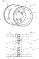
- the amount of vaporized material present within constricted region 4 is determined as a function of axial distance from jets 6, for both the inventive and comparative cases. The results are indicated graphically in Figure 5.
- the x markers indicate the vapor mass fraction (vapor mass divided by total mass) for the comparative case.
- the circular dots indicate the vapor mass fraction for the inventive case.
- the amount of by-products generated is determined for each of the two simulations.
- By-products in the inventive case are reduced by 14% compared to the comparative case.
- the increased pressure drop needed to achieve this benefit is only 8%.
Landscapes
- Chemical & Material Sciences (AREA)
- Chemical Kinetics & Catalysis (AREA)
- Organic Chemistry (AREA)
- Dispersion Chemistry (AREA)
- Organic Low-Molecular-Weight Compounds And Preparation Thereof (AREA)
Claims (5)
- Verfahren zum Mischen von Phosgen mit einem organischen Polyamin, umfassend:Herstellen eines axial gerichteten Phosgenstroms (5) durch eine Leitung, die eine äußere Seitenwand aufweist;Injizieren des organischen Polyamins in die Leitung (15) durch mehrere in Umfangsrichtung gerichtete Strahlen (6), wobei jeder solcher Strahl einen hydrodynamischen Durchmesser Dj aufweist, und jeweils eine Stelle auf einer Wand (2) der Leitung (15) aufweist, um mehrere organische Polyaminströme in den axial gerichteten Phosgenstrom herzustellen; wobei die Leitung (15) eine Querschnittsfläche A an der Stelle des einen oder der mehreren Strahlen (6) aufweist;dann Leiten des Phosgens und des organischen Polyamins durch eine verengte Region (4) der Leitung (15), die eine Querschnittsfläche kleiner als A aufweist, wobei die verengte Region (4) eine kleinste Querschnittsfläche aufweist, die 50 bis 95 % der Querschnittsfläche A beträgt, und wobei die verengte Region (4) stromabwärts von den mehreren Strahlen (6) mit einem Abstand gleich dem 0,01- bis 3-fachen des hydrodynamischen Durchmessers Dj beginnt und sich stromabwärts von den mehreren Strahlen (6) bis zu einem Abstand, der nicht größer als das 50-fache des hydrodynamischen Durchmesser Dj ist, erstreckt; und danach Leiten des Phosgens und des organischen Polyamins in eine Region (8), die eine Querschnittsfläche mindestens so groß wie die Querschnittsfläche A aufweist,wobei die verengte Region (4) durch einen umlaufenden Vorsprung (9) erzeugt wird, der sich auf einer inneren Oberfläche der äußeren Seitenwand (2) der Leitung (15) senkrecht zu dem axial gerichteten Phosgenstrom (5) befindet, undwobei der umlaufende Vorsprung (9) eine gekrümmte Vorderkante (11) aufweist.
- Verfahren nach einem der vorstehenden Ansprüche, wobei die Leitung (15) einen ringförmigen Querschnitt aufweist.
- Verfahren nach einem der Ansprüche 1 bis 2, wobei die Leitung (15) einen kreisförmigen oder elliptischen Querschnitt aufweist.
- Verfahren nach einem der vorstehenden Ansprüche, wobei die Leitung (15) eine Querschnittsbreite von 4 bis 10 mm an der Stelle der Strahlen (6) aufweist, und die Strahlen (6) jeweils einen Durchmesser von 3 bis 7 mm aufweisen.
- Statische Mischvorrichtung (1), umfassend:a) eine Leitung (15), die durch eine äußere Seitenwand (2) und optional eine innere Seitenwand definiert ist, wobei die Leitung (15) eine Längsachse, ein Einlassende zum Einführen eines ersten Fluids und ein Auslassende zum Entfernen eines Reaktionsproduktstroms aufweist, wobei die Leitung (15) einen Fluidströmungsweg definiert;b) eine Vielzahl von in Umfangsrichtung ausgerichtete Strahlen (6), die jeweils eine Stelle auf einer Seitenwand (2) der Leitung (15) zwischen dem Einlass- und dem Auslassende der Leitung (15) aufweisen, wobei jeder Strahl (6) einen Fluidströmungsweg durch die äußere Seitenwand (2) und in die Leitung (15) bereitstellt, und jeder solcher Strahl (6) einen hydraulischen Durchmesser Dj aufweist; wobei die Leitung (15) eine Querschnittsfläche A an der Stelle der Strahlen (6) aufweist;c) eine verengte Region (4) der Leitung (15), wobei die verengte Region (4) eine Querschnittsfläche kleiner als A aufweist und sich stromabwärts von den in Umfangsrichtung ausgerichteten Strahlen (6) und stromaufwärts von dem Auslassende der Leitung (15) befindet, wobei die verengte Region (4) eine kleinste Querschnittsfläche aufweist, die 50 bis 95 % der Querschnittsfläche A beträgt, und wobei die verengte Region (4) stromabwärts von den mehreren Strahlen (6) mit einem Abstand gleich dem 0,01- bis 3-fachen des Durchmessers Dj beginnt und sich stromabwärts von den Strahlen (6) bis zu einem Abstand, der nicht größer als das 50-fache des Durchmesser Dj ist, erstreckt, wobei die verengte Region (4) durch einen umlaufenden Vorsprung (9) erzeugt wird, der sich auf einer inneren Oberfläche der äußeren Seitenwand (2) der Leitung (15) senkrecht zu dem axial gerichteten Phosgenstrom (5) befindet, und wobei der umlaufende Vorsprung (9) eine gekrümmte Vorderkante (11) aufweist; undd) eine Region (8), stromabwärts von und in Fluidkommunikation mit der verengten Region (4) der Leitung (15), die eine Querschnittsfläche von mindestens A aufweist.
Applications Claiming Priority (2)
| Application Number | Priority Date | Filing Date | Title |
|---|---|---|---|
| US201862711652P | 2018-07-30 | 2018-07-30 | |
| PCT/US2019/040554 WO2020027977A1 (en) | 2018-07-30 | 2019-07-03 | Static mixing device and method for mixing phosgene and an organic amine |
Publications (2)
| Publication Number | Publication Date |
|---|---|
| EP3829757A1 EP3829757A1 (de) | 2021-06-09 |
| EP3829757B1 true EP3829757B1 (de) | 2024-04-17 |
Family
ID=67441680
Family Applications (1)
| Application Number | Title | Priority Date | Filing Date |
|---|---|---|---|
| EP19745439.0A Active EP3829757B1 (de) | 2018-07-30 | 2019-07-03 | Statische mischvorrichtung und verfahren zum mischen von phosgen und einem organischen amin |
Country Status (9)
| Country | Link |
|---|---|
| US (1) | US12064733B2 (de) |
| EP (1) | EP3829757B1 (de) |
| JP (1) | JP7369179B2 (de) |
| KR (1) | KR102744577B1 (de) |
| CN (1) | CN112533689A (de) |
| ES (1) | ES2980487T3 (de) |
| HU (1) | HUE067130T2 (de) |
| PT (1) | PT3829757T (de) |
| WO (1) | WO2020027977A1 (de) |
Families Citing this family (1)
| Publication number | Priority date | Publication date | Assignee | Title |
|---|---|---|---|---|
| CN119771328A (zh) * | 2023-10-08 | 2025-04-08 | 万华化学集团股份有限公司 | 一种光气与有机胺的静态混合装置及方法 |
Family Cites Families (15)
| Publication number | Priority date | Publication date | Assignee | Title |
|---|---|---|---|---|
| DE19638567A1 (de) * | 1996-09-20 | 1998-03-26 | Bayer Ag | Mischer-Reaktor und Verfahren zur Durchführung von Reaktionen, insbesondere die Phosgenierung von primären Aminen |
| DE10032269A1 (de) * | 2000-07-03 | 2002-01-31 | Basf Ag | Verfahren und Vorrichtung zur Verringerung von Nebenprodukten bei der Vermischung von Eduktströmen |
| CN101153015B (zh) * | 2006-09-28 | 2010-06-16 | 宁波万华聚氨酯有限公司 | 一种孔射流式反应器及利用该反应器制备异氰酸酯的方法 |
| HUE029625T2 (en) | 2006-11-07 | 2017-03-28 | Basf Se | Process for the preparation of isocyanates |
| EP2179985B1 (de) | 2007-08-21 | 2013-04-10 | Ningbo Wanhua Polyurethanes Co., Ltd. | Mit strömungsleitungen ausgestatteter jetreaktor, verfahren zur herstellung von isocyanaten mittels eines solchen reaktors |
| CN101372463B (zh) | 2007-08-21 | 2011-04-20 | 宁波万华聚氨酯有限公司 | 导流管型射流反应器及利用该反应器制备异氰酸酯的方法 |
| US20100305356A1 (en) * | 2007-08-30 | 2010-12-02 | Basf Se | Method for producing isocyanates |
| CN102119145B (zh) | 2008-08-07 | 2014-06-18 | 巴斯夫欧洲公司 | 制备芳香族异氰酸酯的方法 |
| US8406739B2 (en) * | 2008-11-19 | 2013-03-26 | At&T Mobility Ii Llc | Mediation router |
| US20110230679A1 (en) * | 2010-03-16 | 2011-09-22 | Dow Global Technologies, Inc. | Reactive Static Mixer |
| US20110228630A1 (en) * | 2010-03-16 | 2011-09-22 | Dow Global Technologies, Inc. | Reduced Transit Static Mixer Configuration |
| BR112012031995B1 (pt) * | 2010-06-14 | 2020-02-27 | Dow Global Technologies Llc | Misturador a jato reativo estático |
| WO2012050858A1 (en) * | 2010-09-28 | 2012-04-19 | Dow Global Technologies Llc | Reactive flow static mixer with cross-flow obstructions |
| AT511466B1 (de) | 2011-08-03 | 2012-12-15 | Hoerbiger Kompressortech Hold | Fluidmischer |
| CN104010720A (zh) * | 2011-09-30 | 2014-08-27 | 陶氏环球技术有限责任公司 | 用于胺的光气化的高度隔离的喷射混合器 |
-
2019
- 2019-07-03 EP EP19745439.0A patent/EP3829757B1/de active Active
- 2019-07-03 ES ES19745439T patent/ES2980487T3/es active Active
- 2019-07-03 HU HUE19745439A patent/HUE067130T2/hu unknown
- 2019-07-03 JP JP2021505706A patent/JP7369179B2/ja active Active
- 2019-07-03 KR KR1020217003967A patent/KR102744577B1/ko active Active
- 2019-07-03 PT PT197454390T patent/PT3829757T/pt unknown
- 2019-07-03 CN CN201980050606.7A patent/CN112533689A/zh active Pending
- 2019-07-03 WO PCT/US2019/040554 patent/WO2020027977A1/en not_active Ceased
- 2019-07-03 US US17/257,083 patent/US12064733B2/en active Active
Also Published As
| Publication number | Publication date |
|---|---|
| EP3829757A1 (de) | 2021-06-09 |
| JP2021533127A (ja) | 2021-12-02 |
| PT3829757T (pt) | 2024-06-18 |
| HUE067130T2 (hu) | 2024-10-28 |
| KR102744577B1 (ko) | 2024-12-19 |
| CN112533689A (zh) | 2021-03-19 |
| US12064733B2 (en) | 2024-08-20 |
| JP7369179B2 (ja) | 2023-10-25 |
| KR20210034608A (ko) | 2021-03-30 |
| ES2980487T3 (es) | 2024-10-01 |
| US20210138411A1 (en) | 2021-05-13 |
| WO2020027977A1 (en) | 2020-02-06 |
Similar Documents
| Publication | Publication Date | Title |
|---|---|---|
| KR101050909B1 (ko) | 이소시아네이트의 기상 제조 방법 | |
| US6930199B2 (en) | Process for the preparation of diisocyanates | |
| EP2585203B1 (de) | Statischer reaktiver strahlmischer und mischverfahren während eines amin-phosgen-mischprozesses | |
| US8042988B2 (en) | Hole-jetting type mixer-reactor | |
| US6706913B2 (en) | Process for preparing (cyclo)aliphatic isocyanates | |
| CN101848890B (zh) | 生产异氰酸酯的方法 | |
| KR101179459B1 (ko) | 유동 덕트를 갖는 제트 반응기 및 이것을 이용하여 이소시아네이트를 제조하는 방법 | |
| WO2011115848A1 (en) | Reactive static mixer | |
| WO2008037173A1 (fr) | Réacteur à jet et processus pour la préparation d'un isocyanate au moyen dudit réacteur | |
| MXPA02006804A (es) | Proceso para la preparacion de isocianatos (ciclo) alifaticos. | |
| EP3829757B1 (de) | Statische mischvorrichtung und verfahren zum mischen von phosgen und einem organischen amin | |
| US10435353B2 (en) | Method for producing isocyanates | |
| HUP0700771A2 (en) | Mixing device for mixing two liquids and process for the continuous preparation of organic mono-, di- or polysocianates | |
| EP2151274A1 (de) | Öffnungsstrahl-injektionsreaktor | |
| EP2463270A1 (de) | Verfahren zum Trennen der Reaktionsprodukte nach der Toluenediamin-Phosgenierung in der Gasphase während der Herstellung von Toluoldiisocyanat | |
| WO2024115132A1 (en) | Apparatus and process for preparing isocyanates | |
| WO2025076862A1 (zh) | 一种光气与有机胺的静态混合装置及方法 | |
| CN117500584A (zh) | 用于制备异氰酸酯的反应器和方法 | |
| HK1080450B (en) | Process for preparing isocyanates in the gas phase |
Legal Events
| Date | Code | Title | Description |
|---|---|---|---|
| STAA | Information on the status of an ep patent application or granted ep patent |
Free format text: STATUS: UNKNOWN |
|
| STAA | Information on the status of an ep patent application or granted ep patent |
Free format text: STATUS: THE INTERNATIONAL PUBLICATION HAS BEEN MADE |
|
| PUAI | Public reference made under article 153(3) epc to a published international application that has entered the european phase |
Free format text: ORIGINAL CODE: 0009012 |
|
| STAA | Information on the status of an ep patent application or granted ep patent |
Free format text: STATUS: REQUEST FOR EXAMINATION WAS MADE |
|
| 17P | Request for examination filed |
Effective date: 20210211 |
|
| AK | Designated contracting states |
Kind code of ref document: A1 Designated state(s): AL AT BE BG CH CY CZ DE DK EE ES FI FR GB GR HR HU IE IS IT LI LT LU LV MC MK MT NL NO PL PT RO RS SE SI SK SM TR |
|
| DAV | Request for validation of the european patent (deleted) | ||
| DAX | Request for extension of the european patent (deleted) | ||
| P01 | Opt-out of the competence of the unified patent court (upc) registered |
Effective date: 20230526 |
|
| REG | Reference to a national code |
Ref country code: DE Ref legal event code: R079 Free format text: PREVIOUS MAIN CLASS: B01F0005040000 Ipc: C07C0263100000 Ref country code: DE Ref legal event code: R079 Ref document number: 602019050446 Country of ref document: DE Free format text: PREVIOUS MAIN CLASS: B01F0005040000 Ipc: C07C0263100000 |
|
| GRAP | Despatch of communication of intention to grant a patent |
Free format text: ORIGINAL CODE: EPIDOSNIGR1 |
|
| STAA | Information on the status of an ep patent application or granted ep patent |
Free format text: STATUS: GRANT OF PATENT IS INTENDED |
|
| RIC1 | Information provided on ipc code assigned before grant |
Ipc: B01J 19/26 20060101ALI20231023BHEP Ipc: C07C 263/10 20060101AFI20231023BHEP |
|
| INTG | Intention to grant announced |
Effective date: 20231128 |
|
| GRAS | Grant fee paid |
Free format text: ORIGINAL CODE: EPIDOSNIGR3 |
|
| GRAA | (expected) grant |
Free format text: ORIGINAL CODE: 0009210 |
|
| STAA | Information on the status of an ep patent application or granted ep patent |
Free format text: STATUS: THE PATENT HAS BEEN GRANTED |
|
| AK | Designated contracting states |
Kind code of ref document: B1 Designated state(s): AL AT BE BG CH CY CZ DE DK EE ES FI FR GB GR HR HU IE IS IT LI LT LU LV MC MK MT NL NO PL PT RO RS SE SI SK SM TR |
|
| REG | Reference to a national code |
Ref country code: GB Ref legal event code: FG4D |
|
| REG | Reference to a national code |
Ref country code: CH Ref legal event code: EP |
|
| REG | Reference to a national code |
Ref country code: DE Ref legal event code: R096 Ref document number: 602019050446 Country of ref document: DE |
|
| REG | Reference to a national code |
Ref country code: IE Ref legal event code: FG4D |
|
| REG | Reference to a national code |
Ref country code: PT Ref legal event code: SC4A Ref document number: 3829757 Country of ref document: PT Date of ref document: 20240618 Kind code of ref document: T Free format text: AVAILABILITY OF NATIONAL TRANSLATION Effective date: 20240611 |
|
| REG | Reference to a national code |
Ref country code: NL Ref legal event code: FP |
|
| REG | Reference to a national code |
Ref country code: LT Ref legal event code: MG9D |
|
| REG | Reference to a national code |
Ref country code: AT Ref legal event code: MK05 Ref document number: 1677151 Country of ref document: AT Kind code of ref document: T Effective date: 20240417 |
|
| REG | Reference to a national code |
Ref country code: ES Ref legal event code: FG2A Ref document number: 2980487 Country of ref document: ES Kind code of ref document: T3 Effective date: 20241001 |
|
| PG25 | Lapsed in a contracting state [announced via postgrant information from national office to epo] |
Ref country code: IS Free format text: LAPSE BECAUSE OF FAILURE TO SUBMIT A TRANSLATION OF THE DESCRIPTION OR TO PAY THE FEE WITHIN THE PRESCRIBED TIME-LIMIT Effective date: 20240817 |
|
| PG25 | Lapsed in a contracting state [announced via postgrant information from national office to epo] |
Ref country code: BG Free format text: LAPSE BECAUSE OF FAILURE TO SUBMIT A TRANSLATION OF THE DESCRIPTION OR TO PAY THE FEE WITHIN THE PRESCRIBED TIME-LIMIT Effective date: 20240417 |
|
| PG25 | Lapsed in a contracting state [announced via postgrant information from national office to epo] |
Ref country code: FI Free format text: LAPSE BECAUSE OF FAILURE TO SUBMIT A TRANSLATION OF THE DESCRIPTION OR TO PAY THE FEE WITHIN THE PRESCRIBED TIME-LIMIT Effective date: 20240417 Ref country code: HR Free format text: LAPSE BECAUSE OF FAILURE TO SUBMIT A TRANSLATION OF THE DESCRIPTION OR TO PAY THE FEE WITHIN THE PRESCRIBED TIME-LIMIT Effective date: 20240417 |
|
| PG25 | Lapsed in a contracting state [announced via postgrant information from national office to epo] |
Ref country code: GR Free format text: LAPSE BECAUSE OF FAILURE TO SUBMIT A TRANSLATION OF THE DESCRIPTION OR TO PAY THE FEE WITHIN THE PRESCRIBED TIME-LIMIT Effective date: 20240718 |
|
| PG25 | Lapsed in a contracting state [announced via postgrant information from national office to epo] |
Ref country code: AT Free format text: LAPSE BECAUSE OF FAILURE TO SUBMIT A TRANSLATION OF THE DESCRIPTION OR TO PAY THE FEE WITHIN THE PRESCRIBED TIME-LIMIT Effective date: 20240417 |
|
| PG25 | Lapsed in a contracting state [announced via postgrant information from national office to epo] |
Ref country code: PL Free format text: LAPSE BECAUSE OF FAILURE TO SUBMIT A TRANSLATION OF THE DESCRIPTION OR TO PAY THE FEE WITHIN THE PRESCRIBED TIME-LIMIT Effective date: 20240417 |
|
| REG | Reference to a national code |
Ref country code: HU Ref legal event code: AG4A Ref document number: E067130 Country of ref document: HU |
|
| PG25 | Lapsed in a contracting state [announced via postgrant information from national office to epo] |
Ref country code: LV Free format text: LAPSE BECAUSE OF FAILURE TO SUBMIT A TRANSLATION OF THE DESCRIPTION OR TO PAY THE FEE WITHIN THE PRESCRIBED TIME-LIMIT Effective date: 20240417 |
|
| PG25 | Lapsed in a contracting state [announced via postgrant information from national office to epo] |
Ref country code: PL Free format text: LAPSE BECAUSE OF FAILURE TO SUBMIT A TRANSLATION OF THE DESCRIPTION OR TO PAY THE FEE WITHIN THE PRESCRIBED TIME-LIMIT Effective date: 20240417 Ref country code: NO Free format text: LAPSE BECAUSE OF FAILURE TO SUBMIT A TRANSLATION OF THE DESCRIPTION OR TO PAY THE FEE WITHIN THE PRESCRIBED TIME-LIMIT Effective date: 20240717 Ref country code: LV Free format text: LAPSE BECAUSE OF FAILURE TO SUBMIT A TRANSLATION OF THE DESCRIPTION OR TO PAY THE FEE WITHIN THE PRESCRIBED TIME-LIMIT Effective date: 20240417 Ref country code: IS Free format text: LAPSE BECAUSE OF FAILURE TO SUBMIT A TRANSLATION OF THE DESCRIPTION OR TO PAY THE FEE WITHIN THE PRESCRIBED TIME-LIMIT Effective date: 20240817 Ref country code: HR Free format text: LAPSE BECAUSE OF FAILURE TO SUBMIT A TRANSLATION OF THE DESCRIPTION OR TO PAY THE FEE WITHIN THE PRESCRIBED TIME-LIMIT Effective date: 20240417 Ref country code: GR Free format text: LAPSE BECAUSE OF FAILURE TO SUBMIT A TRANSLATION OF THE DESCRIPTION OR TO PAY THE FEE WITHIN THE PRESCRIBED TIME-LIMIT Effective date: 20240718 Ref country code: FI Free format text: LAPSE BECAUSE OF FAILURE TO SUBMIT A TRANSLATION OF THE DESCRIPTION OR TO PAY THE FEE WITHIN THE PRESCRIBED TIME-LIMIT Effective date: 20240417 Ref country code: BG Free format text: LAPSE BECAUSE OF FAILURE TO SUBMIT A TRANSLATION OF THE DESCRIPTION OR TO PAY THE FEE WITHIN THE PRESCRIBED TIME-LIMIT Effective date: 20240417 Ref country code: AT Free format text: LAPSE BECAUSE OF FAILURE TO SUBMIT A TRANSLATION OF THE DESCRIPTION OR TO PAY THE FEE WITHIN THE PRESCRIBED TIME-LIMIT Effective date: 20240417 Ref country code: RS Free format text: LAPSE BECAUSE OF FAILURE TO SUBMIT A TRANSLATION OF THE DESCRIPTION OR TO PAY THE FEE WITHIN THE PRESCRIBED TIME-LIMIT Effective date: 20240717 |
|
| PG25 | Lapsed in a contracting state [announced via postgrant information from national office to epo] |
Ref country code: DK Free format text: LAPSE BECAUSE OF FAILURE TO SUBMIT A TRANSLATION OF THE DESCRIPTION OR TO PAY THE FEE WITHIN THE PRESCRIBED TIME-LIMIT Effective date: 20240417 |
|
| REG | Reference to a national code |
Ref country code: DE Ref legal event code: R097 Ref document number: 602019050446 Country of ref document: DE |
|
| PG25 | Lapsed in a contracting state [announced via postgrant information from national office to epo] |
Ref country code: EE Free format text: LAPSE BECAUSE OF FAILURE TO SUBMIT A TRANSLATION OF THE DESCRIPTION OR TO PAY THE FEE WITHIN THE PRESCRIBED TIME-LIMIT Effective date: 20240417 |
|
| PG25 | Lapsed in a contracting state [announced via postgrant information from national office to epo] |
Ref country code: CZ Free format text: LAPSE BECAUSE OF FAILURE TO SUBMIT A TRANSLATION OF THE DESCRIPTION OR TO PAY THE FEE WITHIN THE PRESCRIBED TIME-LIMIT Effective date: 20240417 |
|
| PG25 | Lapsed in a contracting state [announced via postgrant information from national office to epo] |
Ref country code: RO Free format text: LAPSE BECAUSE OF FAILURE TO SUBMIT A TRANSLATION OF THE DESCRIPTION OR TO PAY THE FEE WITHIN THE PRESCRIBED TIME-LIMIT Effective date: 20240417 Ref country code: SK Free format text: LAPSE BECAUSE OF FAILURE TO SUBMIT A TRANSLATION OF THE DESCRIPTION OR TO PAY THE FEE WITHIN THE PRESCRIBED TIME-LIMIT Effective date: 20240417 |
|
| PG25 | Lapsed in a contracting state [announced via postgrant information from national office to epo] |
Ref country code: SM Free format text: LAPSE BECAUSE OF FAILURE TO SUBMIT A TRANSLATION OF THE DESCRIPTION OR TO PAY THE FEE WITHIN THE PRESCRIBED TIME-LIMIT Effective date: 20240417 |
|
| PG25 | Lapsed in a contracting state [announced via postgrant information from national office to epo] |
Ref country code: SM Free format text: LAPSE BECAUSE OF FAILURE TO SUBMIT A TRANSLATION OF THE DESCRIPTION OR TO PAY THE FEE WITHIN THE PRESCRIBED TIME-LIMIT Effective date: 20240417 Ref country code: SK Free format text: LAPSE BECAUSE OF FAILURE TO SUBMIT A TRANSLATION OF THE DESCRIPTION OR TO PAY THE FEE WITHIN THE PRESCRIBED TIME-LIMIT Effective date: 20240417 Ref country code: RO Free format text: LAPSE BECAUSE OF FAILURE TO SUBMIT A TRANSLATION OF THE DESCRIPTION OR TO PAY THE FEE WITHIN THE PRESCRIBED TIME-LIMIT Effective date: 20240417 Ref country code: EE Free format text: LAPSE BECAUSE OF FAILURE TO SUBMIT A TRANSLATION OF THE DESCRIPTION OR TO PAY THE FEE WITHIN THE PRESCRIBED TIME-LIMIT Effective date: 20240417 Ref country code: DK Free format text: LAPSE BECAUSE OF FAILURE TO SUBMIT A TRANSLATION OF THE DESCRIPTION OR TO PAY THE FEE WITHIN THE PRESCRIBED TIME-LIMIT Effective date: 20240417 Ref country code: CZ Free format text: LAPSE BECAUSE OF FAILURE TO SUBMIT A TRANSLATION OF THE DESCRIPTION OR TO PAY THE FEE WITHIN THE PRESCRIBED TIME-LIMIT Effective date: 20240417 |
|
| PG25 | Lapsed in a contracting state [announced via postgrant information from national office to epo] |
Ref country code: IT Free format text: LAPSE BECAUSE OF FAILURE TO SUBMIT A TRANSLATION OF THE DESCRIPTION OR TO PAY THE FEE WITHIN THE PRESCRIBED TIME-LIMIT Effective date: 20240417 Ref country code: MC Free format text: LAPSE BECAUSE OF FAILURE TO SUBMIT A TRANSLATION OF THE DESCRIPTION OR TO PAY THE FEE WITHIN THE PRESCRIBED TIME-LIMIT Effective date: 20240417 |
|
| PLBE | No opposition filed within time limit |
Free format text: ORIGINAL CODE: 0009261 |
|
| STAA | Information on the status of an ep patent application or granted ep patent |
Free format text: STATUS: NO OPPOSITION FILED WITHIN TIME LIMIT |
|
| REG | Reference to a national code |
Ref country code: CH Ref legal event code: PL |
|
| PG25 | Lapsed in a contracting state [announced via postgrant information from national office to epo] |
Ref country code: LU Free format text: LAPSE BECAUSE OF NON-PAYMENT OF DUE FEES Effective date: 20240703 |
|
| 26N | No opposition filed |
Effective date: 20250120 |
|
| GBPC | Gb: european patent ceased through non-payment of renewal fee |
Effective date: 20240717 |
|
| PG25 | Lapsed in a contracting state [announced via postgrant information from national office to epo] |
Ref country code: LU Free format text: LAPSE BECAUSE OF NON-PAYMENT OF DUE FEES Effective date: 20240703 |
|
| PG25 | Lapsed in a contracting state [announced via postgrant information from national office to epo] |
Ref country code: CH Free format text: LAPSE BECAUSE OF NON-PAYMENT OF DUE FEES Effective date: 20240731 Ref country code: SI Free format text: LAPSE BECAUSE OF FAILURE TO SUBMIT A TRANSLATION OF THE DESCRIPTION OR TO PAY THE FEE WITHIN THE PRESCRIBED TIME-LIMIT Effective date: 20240417 |
|
| PG25 | Lapsed in a contracting state [announced via postgrant information from national office to epo] |
Ref country code: FR Free format text: LAPSE BECAUSE OF NON-PAYMENT OF DUE FEES Effective date: 20240731 |
|
| PG25 | Lapsed in a contracting state [announced via postgrant information from national office to epo] |
Ref country code: GB Free format text: LAPSE BECAUSE OF NON-PAYMENT OF DUE FEES Effective date: 20240717 |
|
| PGFP | Annual fee paid to national office [announced via postgrant information from national office to epo] |
Ref country code: NL Payment date: 20250613 Year of fee payment: 7 Ref country code: BE Payment date: 20250619 Year of fee payment: 7 |
|
| PGFP | Annual fee paid to national office [announced via postgrant information from national office to epo] |
Ref country code: PT Payment date: 20250624 Year of fee payment: 7 |
|
| PG25 | Lapsed in a contracting state [announced via postgrant information from national office to epo] |
Ref country code: IE Free format text: LAPSE BECAUSE OF NON-PAYMENT OF DUE FEES Effective date: 20240703 |
|
| PGFP | Annual fee paid to national office [announced via postgrant information from national office to epo] |
Ref country code: HU Payment date: 20250630 Year of fee payment: 7 |
|
| PG25 | Lapsed in a contracting state [announced via postgrant information from national office to epo] |
Ref country code: SE Free format text: LAPSE BECAUSE OF FAILURE TO SUBMIT A TRANSLATION OF THE DESCRIPTION OR TO PAY THE FEE WITHIN THE PRESCRIBED TIME-LIMIT Effective date: 20240417 |
|
| PGFP | Annual fee paid to national office [announced via postgrant information from national office to epo] |
Ref country code: ES Payment date: 20250805 Year of fee payment: 7 |
|
| PGFP | Annual fee paid to national office [announced via postgrant information from national office to epo] |
Ref country code: DE Payment date: 20250604 Year of fee payment: 7 |
|
| PG25 | Lapsed in a contracting state [announced via postgrant information from national office to epo] |
Ref country code: CY Free format text: LAPSE BECAUSE OF FAILURE TO SUBMIT A TRANSLATION OF THE DESCRIPTION OR TO PAY THE FEE WITHIN THE PRESCRIBED TIME-LIMIT; INVALID AB INITIO Effective date: 20190703 |