EP3833514B1 - Bras de robot muni d'au moins un capteur de couple d'articulation - Google Patents
Bras de robot muni d'au moins un capteur de couple d'articulation Download PDFInfo
- Publication number
- EP3833514B1 EP3833514B1 EP19749310.9A EP19749310A EP3833514B1 EP 3833514 B1 EP3833514 B1 EP 3833514B1 EP 19749310 A EP19749310 A EP 19749310A EP 3833514 B1 EP3833514 B1 EP 3833514B1
- Authority
- EP
- European Patent Office
- Prior art keywords
- torque sensor
- seal
- robot arm
- joint
- output
- Prior art date
- Legal status (The legal status is an assumption and is not a legal conclusion. Google has not performed a legal analysis and makes no representation as to the accuracy of the status listed.)
- Active
Links
Images

Classifications
-
- B—PERFORMING OPERATIONS; TRANSPORTING
- B25—HAND TOOLS; PORTABLE POWER-DRIVEN TOOLS; MANIPULATORS
- B25J—MANIPULATORS; CHAMBERS PROVIDED WITH MANIPULATION DEVICES
- B25J13/00—Controls for manipulators
- B25J13/08—Controls for manipulators by means of sensing devices, e.g. viewing or touching devices
- B25J13/085—Force or torque sensors
-
- B—PERFORMING OPERATIONS; TRANSPORTING
- B25—HAND TOOLS; PORTABLE POWER-DRIVEN TOOLS; MANIPULATORS
- B25J—MANIPULATORS; CHAMBERS PROVIDED WITH MANIPULATION DEVICES
- B25J9/00—Program-controlled manipulators
- B25J9/10—Program-controlled manipulators characterised by positioning means for manipulator elements
- B25J9/102—Gears specially adapted therefor, e.g. reduction gears
- B25J9/1025—Harmonic drives
-
- B—PERFORMING OPERATIONS; TRANSPORTING
- B25—HAND TOOLS; PORTABLE POWER-DRIVEN TOOLS; MANIPULATORS
- B25J—MANIPULATORS; CHAMBERS PROVIDED WITH MANIPULATION DEVICES
- B25J17/00—Joints
-
- B—PERFORMING OPERATIONS; TRANSPORTING
- B25—HAND TOOLS; PORTABLE POWER-DRIVEN TOOLS; MANIPULATORS
- B25J—MANIPULATORS; CHAMBERS PROVIDED WITH MANIPULATION DEVICES
- B25J19/00—Accessories fitted to manipulators, e.g. for monitoring, for viewing; Safety devices combined with or specially adapted for use in connection with manipulators
- B25J19/0075—Means for protecting the manipulator from its environment or vice versa
-
- F—MECHANICAL ENGINEERING; LIGHTING; HEATING; WEAPONS; BLASTING
- F16—ENGINEERING ELEMENTS AND UNITS; GENERAL MEASURES FOR PRODUCING AND MAINTAINING EFFECTIVE FUNCTIONING OF MACHINES OR INSTALLATIONS; THERMAL INSULATION IN GENERAL
- F16H—GEARING
- F16H49/00—Other gearings
- F16H49/001—Wave gearings, e.g. harmonic drive transmissions
-
- F—MECHANICAL ENGINEERING; LIGHTING; HEATING; WEAPONS; BLASTING
- F16—ENGINEERING ELEMENTS AND UNITS; GENERAL MEASURES FOR PRODUCING AND MAINTAINING EFFECTIVE FUNCTIONING OF MACHINES OR INSTALLATIONS; THERMAL INSULATION IN GENERAL
- F16H—GEARING
- F16H57/00—General details of gearing
- F16H57/02—Gearboxes; Mounting gearing therein
- F16H57/029—Gearboxes; Mounting gearing therein characterised by means for sealing the gearboxes, e.g. to improve airtightness
-
- G—PHYSICS
- G01—MEASURING; TESTING
- G01L—MEASURING FORCE, STRESS, TORQUE, WORK, MECHANICAL POWER, MECHANICAL EFFICIENCY, OR FLUID PRESSURE
- G01L5/00—Apparatus for, or methods of, measuring force, work, mechanical power, or torque, specially adapted for specific purposes
- G01L5/0061—Force sensors associated with industrial machines or actuators
- G01L5/0076—Force sensors associated with manufacturing machines
- G01L5/0085—Force sensors adapted for insertion between cooperating machine elements, e.g. for measuring the nip force between rollers
Definitions
- the invention relates to a robotic arm, having a plurality of links and a plurality of joints which connect the links so that they can be adjusted in relation to one another, at least one downstream link being rotatably mounted on an upstream link by means of a main bearing arrangement, a gear housing of a respective gear being coupled to the upstream link in the relevant joint and a joint torque sensor is connected to an output shaft of the transmission, which is designed to detect a torque on the output side, the joint torque sensor having an input flange, an output flange and a measuring section connecting the input flange to the output flange, on which at least one torque sensor measuring element is arranged .
- a device for example from the EP 1 353 159 B1 and the EP 1 503 196 A1 a device is known in each case, comprising a transmission with a ring gear, which is assigned an electric motor used as a drive.
- a torque sensor forms a unit with the ring gear of a harmonic drive gear or a planetary gear.
- the torque sensor is in the form of a monolithic disc-shaped receiving part, consisting of a circular inner flange with first force application points, a circular outer flange with second force application points and radial connecting webs formed between the two flanges, each with a mechanically weakened section on which pressure or strain-sensitive , Electrical output signals generating transducers are provided.
- the measuring sensors are each connected to quarter, half or full bridges in such a way that a torque can be determined, where the receiving part has a coherent, articulated, flat upper side, and the mechanically weakened sections of the connecting webs are designed as recesses on the underside, each with a thin membrane-like closure, the measuring sensors being applied to the flat, flat upper side of the membrane-like closures.
- the object of the invention is to create a robot arm in which the determination, in particular the measurement of a joint torque, is improved by means of at least one joint torque sensor, and in particular can be carried out more precisely.
- a robot arm having a plurality of links and a plurality of joints which connect the links so that they can be adjusted in relation to one another, at least one downstream link being rotatably mounted on an upstream link by means of a main bearing arrangement, a gear housing of a respective gear in the relevant joint on the upstream member is coupled and a joint torque sensor is connected to an output shaft of the transmission, which is designed to detect a torque on the output side, wherein the joint torque sensor has an input flange, an output flange and a measuring section connecting the input flange to the output flange, on which at least one torque sensor measuring element is arranged, further having a transmission output-side counter surface, on which sits a dynamic contact seal that seals the transmission housing in a lubricant-tight manner, with a gap determined by the main bearing arrangement between the upstream link and the downstream link, to which the output flange of the joint torque sensor is coupled, by means of a further seal is sealed.
- the features according to the invention pursue the goal of increasing the accuracy of the moment measurement by optimizing the tributary forces.
- the further seal can be arranged at any point in the area of the transmission output. It is important, however, that the arrangement of the further seal is selected such that the further seal is arranged in the torque flow in front of the at least one torque sensor measuring element, so that the further seal does not form a secondary force flow that falsifies the measurement by the at least one torque sensor measuring element could.
- a robot arm having a plurality of links and a plurality of joints which connect the links so that they can be adjusted in relation to one another, with at least one downstream link being rotatably mounted on an upstream link by means of a main bearing arrangement, a gear housing of a respective gear in the relevant joint the upstream member is coupled and a joint torque sensor is connected to an output shaft of the transmission, which is designed to detect a torque on the output side, the joint torque sensor having an input flange, an output flange and a measuring section connecting the input flange to the output flange, on which at least one torque sensor -Measuring element is arranged, further comprising a coupling section which couples the input flange of the joint torque sensor to the output shaft of the transmission and has a counter surface on which the transmission housing sch fluid-tight sealing dynamic contact seal is seated, with a gap determined by the main bearing arrangement between the upstream link and the downstream link, to which the output flange of the joint torque sensor is coupled
- a torque sensor or joint torque sensor is generally integrated into the relevant robot joint to measure output torques, in particular together with a drive motor, a gearbox and a main bearing for the Joint.
- the joint torque sensor is only loaded with a torque. Tilting moments and other forces are transmitted via the main bearing.
- the exclusive torque load is the main advantage compared to a sequential arrangement of engine, transmission including main bearing and joint torque sensor.
- This shunt force can lead to a deterioration in measurement accuracy of up to a few percent of the nominal torque.
- a special focus in the joint design is therefore on reducing the sealing friction.
- this focus represents an additional cost factor if the minimization of friction is to be achieved with high-quality materials and/or coatings, and on the other hand, there is a conflict of objectives between a high sealing effect and high measurement accuracy. It is actually not possible to achieve both at the same time in an ideal way.
- the goal of the invention can therefore be seen as realizing a seal for a robot joint with integrated joint torque sensors with a better sealing effect, but without the torque measurement being falsified.
- the sealing of the transmission can be arranged between the transmission and the joint torque sensor, for example directly following a flex spline of a stress wave transmission.
- the seal of the transmission can thus be located between a main bearing inner ring and an inner flange of the joint torque sensor.
- a complete sealing of the transmission can thus be achieved.
- Typical frictional torques from contacting seals are one to two percent of the nominal torque of the joint torque sensor.
- the seal does not represent a shunt force that influences the torque measurement.
- the torque measurement takes place in the power flow only after the seal of the transmission.
- the torque applied to the structural part of the robot arm, i.e. to a link of the robot arm is thus almost completely measured by the joint torque sensor, only minus a theoretical tributary force of the main bearing.
- the requirements for sealing the main bearing are significantly lower compared to the transmission seal. For example, only a minimal, ie smaller amount of fat is required and the fat consistency can also have a lower viscosity. It is even possible to use non-contact seals, such as cover disks, which only represent a minimal shunt of force and hardly affect the torque measurement at all. Due to the principle, the secondary flow of forces due to bearing friction cannot be prevented. However, this friction can be significantly minimized. Rather, the friction of the seal is decisive.
- the main bearing arrangement can comprise one or more roller bearings which are designed to mount the link downstream in the kinematic chain of the robot arm with respect to a joint in an adjustable manner on a link upstream of this joint.
- the joint can preferably be a swivel joint.
- the main bearing arrangement can be designed to rotatably support the link downstream in the kinematic chain of the robot arm with respect to a joint on a link upstream of this joint. Accordingly, due to the main bearing arrangement, a gap is formed between the downstream link and the upstream link, since the adjustability of the downstream link with respect to the upstream link must be ensured. To this extent, the gap is formed by two opposing end walls of the upstream link and the downstream link.
- the mentioned gap can also be formed by an inner ring and an outer ring of a roller bearing.
- the non-contact seal can thus in particular be arranged between an inner ring and an outer ring of a roller bearing of the main bearing assembly.
- the downstream link which is adjustably mounted by means of the main bearing arrangement, is driven by a motor, in particular an electric motor.
- the motor can be arranged in the upstream link.
- the engine generates a drive torque, which is preferably transmitted to the downstream member via a gearbox.
- the transmission has a transmission housing. Since the transmission generally includes at least one rolling pair that is designed to be lubricated, the transmission housing serves, among other things, to enclose grease and/or oil within the transmission housing. Critical here is the sealing of gaps, in particular in the area of a transmission housing passage, both on an input element of the transmission and on an output element of the transmission.
- the input element of the transmission can be part of a shaft generator of the tension shaft transmission.
- the output link of the transmission can be part of a flex spline of the stress shaft transmission.
- a lubricant-tight seal is understood in particular to mean that, depending on the type of transmission and the lubricant present in the transmission, be it grease and/or oil, the dynamic contact seals can seal in such a way that grease and/or oil is at least approximately or completely prevented exits from the gaps between the transmission housing and the input member and the output member.
- the output element of the transmission can form the output shaft of the transmission or can be connected to it.
- the output member or the driven shaft can be formed by a flex spline of the tension shaft transmission or preferably be directly connected to it.
- the joint torque sensor includes the input flange, the output flange and at least one, in particular a plurality of measuring sections. At least one joint torque sensor can be present at each joint of the robot arm. Each joint torque sensor can have a monolithic block, which in this respect can include the input flange, the output flange and the at least one, in particular the multiple, measuring sections.
- the input flange can in particular be formed by an inner ring part of the block
- the output flange can be formed by an outer ring part of the block, the inner ring part and the outer ring part being connected via a number of spoke sections.
- the spoke sections are part of the gauge sections. Each spoke section carries at least one, in particular several, measuring sensors, such as strain gauges (DMS).
- the joint torque sensor can, for example, analogous to the EP 1 353 159 B1 and the EP 1 503 196 A1 be trained.
- the coupling section forms a torque-transmitting connection between the output member of the transmission and the input flange of the joint torque sensor.
- the coupling section can be a separate component, for example, which can be detachably connected to the output member of the transmission on the one hand and to the input flange of the joint torque sensor on the other hand.
- the coupling section can be part of the output link of the transmission or can be formed in one piece with the output link of the transmission.
- the coupling section can be part of the Be input flange of the joint torque sensor or be integrally formed with the input flange of the joint torque sensor.
- the dynamic contact seal that seals the transmission housing in a lubricant-tight manner can be designed as at least one radial shaft sealing ring.
- the radial shaft sealing ring can have a sealing lip or a plurality of sealing lips which are in contact with the counter surface of the coupling section. Instead of a single radial shaft seal, two or more radial shaft seals can also be provided.
- the coupling section can be formed on the output shaft of the transmission and the counter surface, on which a sealing lip of the radial shaft seal rests in contact, can be formed by a casing wall of the output shaft.
- the coupling section is a partial section of the output shaft of the transmission.
- the coupling section can be formed on the input flange of the joint torque sensor and the mating surface, on which a sealing lip of the radial shaft seal rests in contact, can be formed by a casing wall of the input flange of the joint torque sensor.
- the coupling section is a partial section of the input flange of the joint torque sensor.
- the coupling section can be designed as a separate component that is attached to the input flange of the joint torque sensor and/or to the output shaft of the transmission and the counter surface, on which a sealing lip of the radial shaft seal rests touching, are formed by a casing wall of the separate component.
- the coupling section which is designed as a separate component, can be screwed to the input flange of the joint torque sensor on the one hand and to the output shaft of the transmission on the other hand, for example by means of screws.
- the dynamic, non-contact seal that seals the gap between the upstream link and the downstream link in a dust-tight manner can be designed as at least one gap seal or labyrinth seal.
- the gap seal or labyrinth seal can be arranged either between an inner ring of a roller bearing of the main bearing assembly and an outer ring of the roller bearing of the main bearing assembly or between the upstream member and the downstream member of the relevant joint.
- the dynamic, non-contact seal that seals the gap between the upstream link and the downstream link, in particular in a dust-tight manner can be designed as at least one sealing disk of the main bearing arrangement.
- the at least one sealing disk can be arranged in particular between an inner ring of a roller bearing of the main bearing arrangement and an outer ring of the roller bearing of the main bearing arrangement.
- the sealing disk can be part of the roller bearing.
- the robot arm can generally have a plurality of motors, each of which is designed to adjust one of the joints, in that the motor is fixed with its motor housing to a link of the robot arm that is in front of the respective joint, with a motor shaft of the motor being coupled to an input link of the gear , Having an output member, which at a downstream of the respective joint Member of the robot arm is coupled by the output member forms the output shaft of the transmission and is coupled via the coupling portion to the input flange of the joint torque sensor.
- the motors can preferably be electric motors.
- the robot arm can have a sealing arrangement according to the invention on each of its joints.
- the respective transmission housing can be sealed in a lubricant-tight manner with respect to the motor shaft by means of at least one further dynamic contact seal.
- the transmission thus has a transmission housing. Since the gear, as already mentioned, generally comprises at least one rolling pair that is designed to be lubricated, the gear housing serves, among other things, to enclose grease and/or oil within the gear housing. Critical here is the sealing of gaps, in particular in the area of a transmission housing passage, both on an input element of the transmission and on an output element of the transmission. Accordingly, these gaps between the transmission housing and the input member or the output member are sealed in a lubricant-tight manner by means of dynamic contact seals.
- a lubricant-tight seal is understood in particular to mean that, depending on the type of transmission and the lubricant present in the transmission, be it grease and/or oil, the dynamic contact seals can seal in such a way that grease and/or oil is at least approximately or completely prevented exits from the gaps between the transmission housing and the input member and the output member.
- the at least one further dynamic contact seal can be designed as a further radial shaft seal.
- the further radial shaft sealing ring can have a sealing lip or a plurality of sealing lips which are in contact with the motor shaft.
- a single radial shaft seal two or more radial shaft seals can also be provided.
- lubricant such as grease and/or transmission oil
- the dynamic non-contact seal that seals the gap determined by the main bearing assembly between the upstream link and the downstream link coupled to the output flange of the joint torque sensor, particularly dust-tight, may be the only seal sealing the gap of the joint in question.
- an effect according to the invention is also achieved to a sufficient degree if necessary if no completely non-contact seal is used, but a different seal, possibly working in contact to a small extent, is used, which has significantly reduced friction compared to a general contact seal and in particular compared to a known radial shaft seal.
- seals are sometimes also referred to as low-friction seals.
- seals can, for example, be seals in the form of a radial shaft sealing ring, which, however, is then designed without a hose spring and thus has significantly less pressure on the associated shaft. If necessary, the seal can also be designed as a felt ring, which surrounds the associated shaft almost flush without radial pressure.
- the dynamic contact seal that abuts the coupling portion may be attached to a first support ring that is connected to an inner race of the main bearing.
- the output flange of the joint torque sensor may be attached to a second support ring that is connected to an outer ring of the main bearing.
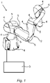
- a robot 1 has a robot arm 2 with an associated robot controller 3 .
- the robot arm 2 has a plurality of links 4 and the links 4 have joints 5 which can be adjusted relative to one another.
- Each joint 5 is powered by a motor 9 ( 2 ) of the robot arm 2 is driven.
- the robot controller 3 is designed and set up to control the motors 9 in order to move the limbs 4 of the robot arm 2 by automatically adjusting the joints 5 .
- the robot arm 2 has at least one joint 5, which has a joint sealing arrangement according to the invention, which is shown in 2 is shown in more detail in section.
- all joints 5 of the robot arm 2 are designed as rotary joints 5a.
- each rotary joint 5a is pivotable about an axis of rotation D ( 2 ) rotatable and has a joint sealing arrangement according to the invention.
- the robot arm 2 has a plurality of motors 9, each of which is designed to adjust one of the joints 5, in that the motor 9 is fixed with its motor housing 9a to a link 4a of the robot arm 2 located in front of the respective joint 5 and a motor shaft 9b of the motor 9 is coupled to an input member 7.1 of the transmission 7, which has an output member 7.2, which is coupled to a member 4b of the robot arm 2 downstream of the respective joint 5, in that the output member 7.2 drives the output shaft 8 of the Transmission 7 forms and is coupled via the coupling section 12 to the input flange 10.1 of the joint torque sensor 10.
- the robot arm 2 accordingly has a plurality of links 4 and a plurality of joints 5, which connect the links 4 in an adjustable manner relative to one another, with a respective downstream link 4b being rotatably mounted on an upstream link 4a by means of a main bearing arrangement 6, a gear housing 7a of a respective gear 7 in the
- the relevant joint 5 is coupled to the downstream link 4b and a joint torque sensor 10 is connected to an output shaft 8 of the transmission 7, which is designed to detect a torque on the output side, the joint torque sensor 10 having an input flange 10.1, an output flange 10.3 and an input flange 10.1 measuring section 10.2 connecting to the output flange 10.3, on which at least one torque sensor measuring element 11 is arranged, further having a coupling section 12 coupling the input flange 10.1 of the joint torque sensor 10 to the output shaft 8 of the transmission 7, which has a counter-rotating surface 13 on which a dynamic contact seal 14 sealing the transmission housing 7a in a lubricant-tight manner is seated, with a
- the dynamic contact seal 14 that seals the transmission housing 7a in a lubricant-tight manner is designed as at least one radial shaft sealing ring.
- the coupling section 12 is formed on the input flange 10.1 of the joint torque sensor 10 and the mating surface 13, on which a sealing lip 14a of the radial shaft seal rests in contact, is formed by a casing wall of the input flange 10.1 of the joint torque sensor 10.
- the dynamic, non-contact seal 16 sealing the gap 15 between the upstream member 4a and the downstream member 4b in a dust-tight manner is designed as at least one gap seal, labyrinth seal or in particular as at least one sealing disk.
- the respective transmission housing 7a is sealed in a lubricant-tight manner with respect to the motor shaft 9b by means of at least one further dynamic contact seal 17 .
- the at least one further dynamic contact seal 17 is designed as a further radial shaft sealing ring.
- the transmission housing 7a is dynamically sealed against the escape of transmission oil exclusively by means of the dynamic contact seal 14, which rests on the coupling section 12, and the further dynamic contact seal 17, which rests on the motor shaft 9b.
- the dynamic, non-contacting seal 16 which seals the gap 15 defined by the main bearing assembly 6 between the upstream member 4a and the downstream member 4b, to which the output flange 10.3 of the joint torque sensor 10 is coupled, dust-tight, is the only seal sealing the gap 15 of the relevant joint 5.
- the dynamic contact seal 14, which abuts the coupling section 12, is fixed to a first support ring 18.1, which is connected to an inner ring 6.1 of the main bearing 6.
- the output flange 10.3 of the joint torque sensor 10 is attached to a second support ring 18.2, which is connected to an outer ring 6.2 of the main bearing 6.
Landscapes
- Engineering & Computer Science (AREA)
- Mechanical Engineering (AREA)
- Robotics (AREA)
- Chemical & Material Sciences (AREA)
- Analytical Chemistry (AREA)
- General Engineering & Computer Science (AREA)
- Human Computer Interaction (AREA)
- Physics & Mathematics (AREA)
- General Physics & Mathematics (AREA)
- Manipulator (AREA)
Claims (15)
- Bras robotique ayant une pluralité de liaisons (4) et une pluralité de joints (5) qui relient les liaisons (4) de manière à ce qu'elles puissent être ajustées les unes par rapport aux autres, au moins une liaison en aval (4b) étant montée en rotation sur une liaison amont (4a) au moyen d'une disposition de roulement principal (6). un boîtier d'engrenage (7a) d'un engrenage respectif (7) est couplé à la liaison amont (4a) dans le joint concerné (5) et un capteur de couple de joint (10) est connecté à un arbre de sortie (8) de l'engrenage (7). est connecté, qui est conçu pour détecter un couple du côté de sortie, le capteur de couple de joint (10) ayant une bride d'entrée (10.1), une bride de sortie (10.3) et une section de mesure (10.2) reliant la bride d'entrée (10.1) à la bride de sortie (10.3), sur laquelle au moins un élément de mesure de capteur de couple (11) est disposé, caractérisé par une contre-surface (13) du côté de la sortie de transmission, sur lequel est installé un roulement dynamique scellant le boîtier de transmission (7a) de manière étanche au lubrifiant ( joint de contact (14), avec un espace (15) déterminé par la disposition du roulement principal (6) entre l'élément amont (4a) et l'élément aval (4b) auquel est couplée la bride de sortie (10.3) du capteur de couple commun (10), est scellé au moyen d'un joint dynamique supplémentaire (16).
- Bras robotisé selon la revendication 1, caractérisé par une section d'accouplement (12) qui couple la bride d'entrée (10.1) du capteur de couple commun (10) à l'arbre de sortie (8) de l'engrenage (7) et présente une contre-surface (13) sur laquelle est assis le boîtier d'engrenage (7a) Joint de contact dynamique étanche au lubrifiant (14), avec un espace (15) déterminé par la disposition du roulement principal (6) entre l'élément amont (4a) et l'élément aval (4b) auquel est assis la bride de sortie (10.3) du capteur de couple Joint (10) est couplée, au moyen de la dynamique supplémentaire, en particulier le joint sans contact (16) est scellé en particulier étanche à la poussière.
- Bras de robot selon la revendication 1 ou 2, caractérisé en ce que le joint de contact dynamique (14) qui scelle le boîtier d'engrenage (7a) de manière étanche au lubrifiant est conçu comme au moins une bague d'étanchéité radiale d'arbre.
- Bras robotisé selon la revendication 3, caractérisé en ce que la section d'accouplement (12) est formée sur l'arbre de sortie (8) de l'engrenage (7) et la contre-surface (13), sur laquelle repose une lèvre d'étanchéité (14a) du joint radial de l'arbre, est formée par une paroi de boîtier de l'arbre de sortie (8) est formée.
- Bras robotisé selon la revendication 3, caractérisé en ce que la section d'accouplement (12) est formée sur la bride d'entrée (10.1) du capteur de couple articulaire (10) et la surface d'accouplement (13), sur laquelle repose en contact une lèvre d'étanchéité (14a) du joint radial de l'arbre, à partir d'une paroi de boîtier de la bride d'entrée (10.1) du capteur de couple articulaire (10).
- Bras robotisé selon la revendication 3, caractérisé en ce que la section d'accouplement (12) est conçue comme un composant séparé qui est fixé à la bride d'entrée (10.1) du capteur de couple de joint (10) et/ou à l'arbre de sortie (8) de l'engrenage (7) et à la surface d'accouplement (13), sur laquelle repose une lèvre d'étanchéité (14a) du joint radial de l'arbre, est formé par une paroi de boîtier du composant séparé.
- Bras robotisé selon l'une des revendications 1 à 6, caractérisé en ce que le joint dynamique sans contact (16) scellant l'espace (15) entre l'élément amont (4a) et l'élément aval (4b) de manière étanche à la poussière comme au moins un joint d'étanchéité à l'espace ou un joint labyrinthe est formé.
- Bras robotisé selon l'une des revendications 1 à 7, caractérisé en ce que le joint dynamique sans contact (16) scellant l'espace (15) entre l'élément amont (4a) et l'élément aval (4b) de manière étanche à la poussière comme au moins un disque d'étanchéité de la disposition principale du roulement est formé.
- Bras de robot selon l'une des revendications 1 à 8, caractérisé en ce que le bras de robot (2) possède une pluralité de moteurs (9) qui sont chacun conçus pour ajuster l'un des joints (5) en ce que le moteur (9) est fixé avec son carter moteur (9a) à une liaison (4a) du bras robot (2) situé devant le joint respectif (5) et un arbre moteur (9b) du moteur (9) à une entrée La liaison (7.1) de l'engrenage (7) est couplée, qui a un élément de sortie (7.2), qui est couplé à un élément (4b) du bras du robot (2) en aval du joint respectif (5), en ce sens que l'élément de sortie (7.2) entraîne l'arbre de sortie (8) de l'engrenage (7 ) et est couplé via la section d'accouplement (12) à la bride d'entrée (10.1) du capteur de couple de joint (10).
- Bras de robot selon la revendication 9, caractérisé en ce que le boîtier d'engrenage respectif (7a) est scellé de manière étanche au lubrifiant par rapport à l'arbre du moteur (9b) au moyen d'au moins un autre joint de contact dynamique (17).
- Bras de robot selon la revendication 10, caractérisé en ce que l'au moins un autre joint de contact dynamique (17) est conçu comme une autre bague d'étanchéité radiale de l'arbre.
- Bras robotique selon la revendication 10 ou 11, caractérisé en ce que le boîtier d'engrenage (7a) est fixé exclusivement au moyen du joint de contact dynamique (14) qui jouxte la section d'accouplement (12) et que le joint de contact dynamique supplémentaire (17) qui est fixé à l'arbre du moteur (9b) est en contact, est scellé dynamiquement contre la fuite d'huile pour engrenages.
- Bras robotique selon l'une quelconque des revendications 1 à 12, caractérisé en ce que le joint dynamique sans contact (14) qui comble l'écart (15) déterminé par la disposition du roulement principal (6) entre la liaison amont (4a) et la liaison aval (4b), à laquelle est couplée la bride de sortie (10.3) du capteur de couple commun (10), est étanche à la poussière, est le seul joint du joint pertinent (5) qui scelle l'espace (15) .
- Bras robotique selon l'une quelconque des revendications 1 à 13, caractérisé en ce que le joint de contact dynamique (14) qui jouxte la partie d'accouplement (12) est fixé à une première bague de support (18.1) qui est reliée à une bague intérieure (6.1) du roulement principal (6) est raccordée.
- Bras de robot selon l'une des revendications 1 à 14, caractérisé en ce que la bride de sortie (10.3) du capteur de couple commun (10) est fixée à une seconde bague de support (18.2) qui est reliée à une bague extérieure (6.2) du roulement principal (6).
Applications Claiming Priority (2)
| Application Number | Priority Date | Filing Date | Title |
|---|---|---|---|
| DE102018213452.9A DE102018213452A1 (de) | 2018-08-09 | 2018-08-09 | Roboterarm mit wenigstens einem Gelenkmomentsensor |
| PCT/EP2019/070648 WO2020030498A1 (fr) | 2018-08-09 | 2019-07-31 | Bras de robot muni d'au moins un capteur de couple d'articulation |
Publications (2)
| Publication Number | Publication Date |
|---|---|
| EP3833514A1 EP3833514A1 (fr) | 2021-06-16 |
| EP3833514B1 true EP3833514B1 (fr) | 2022-09-21 |
Family
ID=67539498
Family Applications (1)
| Application Number | Title | Priority Date | Filing Date |
|---|---|---|---|
| EP19749310.9A Active EP3833514B1 (fr) | 2018-08-09 | 2019-07-31 | Bras de robot muni d'au moins un capteur de couple d'articulation |
Country Status (6)
| Country | Link |
|---|---|
| US (1) | US11267133B2 (fr) |
| EP (1) | EP3833514B1 (fr) |
| KR (1) | KR102730590B1 (fr) |
| CN (1) | CN112584983B (fr) |
| DE (1) | DE102018213452A1 (fr) |
| WO (1) | WO2020030498A1 (fr) |
Families Citing this family (4)
| Publication number | Priority date | Publication date | Assignee | Title |
|---|---|---|---|---|
| JP7058929B2 (ja) * | 2015-10-27 | 2022-04-25 | キヤノン株式会社 | 駆動装置、ロボット装置、制御方法、物品の製造方法、制御プログラム、および記録媒体 |
| US11312006B2 (en) * | 2018-03-30 | 2022-04-26 | Fanuc Corporation | Robot drive unit and robot |
| CN115298000B (zh) * | 2020-03-18 | 2025-07-11 | 发那科株式会社 | 具备力传感器的旋转轴构造和机器人 |
| CN118922653A (zh) * | 2023-02-14 | 2024-11-08 | 谐波传动系统有限公司 | 带扭矩传感器的波动齿轮装置 |
Family Cites Families (18)
| Publication number | Priority date | Publication date | Assignee | Title |
|---|---|---|---|---|
| JP3585008B2 (ja) * | 1996-02-15 | 2004-11-04 | 株式会社ハーモニック・ドライブ・システムズ | 密閉型波動歯車装置 |
| DE50302070D1 (de) | 2002-04-12 | 2006-02-02 | Deutsch Zentr Luft & Raumfahrt | Verfahren und Einrichtung zum Messen des Abtriebsdrehmoments eines Elektromotors mit einem diesem nachgeordneten Getriebe |
| DE10317304A1 (de) * | 2002-04-12 | 2003-12-11 | Deutsch Zentr Luft & Raumfahrt | Verfahren und Einrichtung zum Bestimmen eines Abtriebsdrehmoments eines Elektromotors |
| DE102008005901B4 (de) * | 2008-01-24 | 2018-08-09 | Deutsches Zentrum für Luft- und Raumfahrt e.V. | Sterilbarriere für einen chirurgischen Roboter mit Drehmomentsensoren |
| CN101797748A (zh) * | 2010-01-08 | 2010-08-11 | 武汉若比特机器人有限公司 | 一种多自由度排爆机械臂 |
| KR101309652B1 (ko) | 2011-08-10 | 2013-09-17 | 주식회사 로보스타 | 축마다 중공형 구동모듈 및 1축 토크센서가 장착된 산업용 직접교시 로봇 |
| CN202732858U (zh) * | 2012-06-11 | 2013-02-13 | 苏州绿的谐波传动科技有限公司 | 一种中空型谐波减速机 |
| KR101428328B1 (ko) * | 2012-12-27 | 2014-08-08 | 현대자동차주식회사 | 로봇의 보행제어방법 및 시스템 |
| DE102013216449A1 (de) * | 2013-08-20 | 2015-02-26 | Kuka Roboter Gmbh | Industrieroboter mit wenigstens einem Antrieb |
| CN105518345B (zh) * | 2014-05-16 | 2018-02-02 | 谐波传动系统有限公司 | 中空波动齿轮装置及中空致动器 |
| EP3242775B1 (fr) * | 2015-01-07 | 2021-12-22 | ABB Schweiz AG | Procédé pour l'estimation de forces externes et de couples sur un bras de robot |
| DE102015200374A1 (de) * | 2015-01-13 | 2016-07-14 | Kuka Roboter Gmbh | Getriebe, elektrische Antriebsvorrichtung und Industrieroboter |
| JP6632204B2 (ja) * | 2015-03-13 | 2020-01-22 | キヤノン株式会社 | 駆動装置、ロボット装置、および物品の製造方法 |
| JP2017034936A (ja) | 2015-08-05 | 2017-02-09 | 国立大学法人長岡技術科学大学 | モータ制御装置、モータ装置、及びモータ制御方法 |
| JP7058929B2 (ja) | 2015-10-27 | 2022-04-25 | キヤノン株式会社 | 駆動装置、ロボット装置、制御方法、物品の製造方法、制御プログラム、および記録媒体 |
| JP6492329B2 (ja) * | 2016-01-29 | 2019-04-03 | 株式会社安川電機 | ロボット |
| JP6506227B2 (ja) * | 2016-08-31 | 2019-04-24 | ファナック株式会社 | 関節構造およびロボット |
| US11092225B2 (en) * | 2017-02-28 | 2021-08-17 | Harmonic Drive Ag | Strain wave gear mechanism with an inner seal |
-
2018
- 2018-08-09 DE DE102018213452.9A patent/DE102018213452A1/de not_active Ceased
-
2019
- 2019-07-31 US US17/267,222 patent/US11267133B2/en active Active
- 2019-07-31 KR KR1020217005917A patent/KR102730590B1/ko active Active
- 2019-07-31 WO PCT/EP2019/070648 patent/WO2020030498A1/fr not_active Ceased
- 2019-07-31 EP EP19749310.9A patent/EP3833514B1/fr active Active
- 2019-07-31 CN CN201980053351.XA patent/CN112584983B/zh active Active
Also Published As
| Publication number | Publication date |
|---|---|
| US11267133B2 (en) | 2022-03-08 |
| WO2020030498A1 (fr) | 2020-02-13 |
| DE102018213452A1 (de) | 2020-02-13 |
| EP3833514A1 (fr) | 2021-06-16 |
| KR102730590B1 (ko) | 2024-11-14 |
| KR20210041583A (ko) | 2021-04-15 |
| CN112584983A (zh) | 2021-03-30 |
| CN112584983B (zh) | 2024-07-12 |
| US20210308873A1 (en) | 2021-10-07 |
Similar Documents
| Publication | Publication Date | Title |
|---|---|---|
| EP3833514B1 (fr) | Bras de robot muni d'au moins un capteur de couple d'articulation | |
| EP3766646B1 (fr) | Train d'engrenage de type roue cycloïdale pourvu de dispositif de détection de couple | |
| DE2559987C2 (de) | Vorrichtung zum Ermitteln der Steifigkeit eines Bauteils und Schaltung zum Bestimmen eines Gradienten | |
| DE69202976T2 (de) | Axialkompakter Drehmomentwandler. | |
| DE102018124685B4 (de) | Drehmomentmessvorrichtung für ein Spannungswellengetriebe | |
| DE4239947C1 (de) | Antriebseinheit zur steuerung und regelung von armaturen o. dgl. | |
| EP3507580A1 (fr) | Capteur de couple à transmission de couple élastique radialement | |
| EP3743701A1 (fr) | Système de mesure et procédé permettant de déterminer une force et/ou un couple au niveau d'un arbre de transmission de couple | |
| DE102016010549A1 (de) | Drehmomentsensor mit Nebenschlussspeiche | |
| WO2008074501A1 (fr) | Dispositif de dépistage précoce de défaillances sur des machines et/ou sur leurs éléments | |
| DE10317304A1 (de) | Verfahren und Einrichtung zum Bestimmen eines Abtriebsdrehmoments eines Elektromotors | |
| DE19601290A1 (de) | Kreuzgelenkanordnung für eine Gelenkwelle | |
| EP1543305B1 (fr) | Capteur de force servant a mesurer des forces d'arbre | |
| DE3604653C2 (fr) | ||
| DE1773547A1 (de) | Ringfoermige Druckkraftgeberzelle | |
| EP1607714B1 (fr) | Procédé et dispositif pour mesurer le jeu d'un joint pivotable | |
| AT402978B (de) | Getriebe für den antrieb von oder in landwirtschaftlichen geräten | |
| DE202005006590U1 (de) | Richt- und Stabilisierungsanlage mit einer Kraftmessvorrichtung zur Drehmomentmessung | |
| DE102015221745A1 (de) | Verfahren und Vorrichtung zur Bestimmung eines Drehmoments sowie Antriebseinheit | |
| DE3922194C1 (fr) | ||
| DE4325403A1 (de) | Verspannungsprüfstand | |
| EP4061759A1 (fr) | Dispositif de surveillance de vitesse d'un système de transport de passagers | |
| EP3969222B1 (fr) | Unité d'application à mesure de la force de pression | |
| DE102016010546B3 (de) | Drehmomentsensor mit axialem Anschlagelement | |
| DE19720325C1 (de) | Kraftmeßeinrichtung in einem Stellantrieb zur Steuerung von Armaturen |
Legal Events
| Date | Code | Title | Description |
|---|---|---|---|
| STAA | Information on the status of an ep patent application or granted ep patent |
Free format text: STATUS: UNKNOWN |
|
| STAA | Information on the status of an ep patent application or granted ep patent |
Free format text: STATUS: THE INTERNATIONAL PUBLICATION HAS BEEN MADE |
|
| PUAI | Public reference made under article 153(3) epc to a published international application that has entered the european phase |
Free format text: ORIGINAL CODE: 0009012 |
|
| STAA | Information on the status of an ep patent application or granted ep patent |
Free format text: STATUS: REQUEST FOR EXAMINATION WAS MADE |
|
| 17P | Request for examination filed |
Effective date: 20210211 |
|
| AK | Designated contracting states |
Kind code of ref document: A1 Designated state(s): AL AT BE BG CH CY CZ DE DK EE ES FI FR GB GR HR HU IE IS IT LI LT LU LV MC MK MT NL NO PL PT RO RS SE SI SK SM TR |
|
| DAV | Request for validation of the european patent (deleted) | ||
| DAX | Request for extension of the european patent (deleted) | ||
| GRAP | Despatch of communication of intention to grant a patent |
Free format text: ORIGINAL CODE: EPIDOSNIGR1 |
|
| STAA | Information on the status of an ep patent application or granted ep patent |
Free format text: STATUS: GRANT OF PATENT IS INTENDED |
|
| RIC1 | Information provided on ipc code assigned before grant |
Ipc: G01L 5/00 20060101ALI20220401BHEP Ipc: F16H 57/029 20120101ALI20220401BHEP Ipc: F16H 49/00 20060101ALI20220401BHEP Ipc: B25J 17/00 20060101ALI20220401BHEP Ipc: B25J 13/08 20060101ALI20220401BHEP Ipc: B25J 9/10 20060101AFI20220401BHEP |
|
| INTG | Intention to grant announced |
Effective date: 20220414 |
|
| GRAS | Grant fee paid |
Free format text: ORIGINAL CODE: EPIDOSNIGR3 |
|
| GRAA | (expected) grant |
Free format text: ORIGINAL CODE: 0009210 |
|
| STAA | Information on the status of an ep patent application or granted ep patent |
Free format text: STATUS: THE PATENT HAS BEEN GRANTED |
|
| AK | Designated contracting states |
Kind code of ref document: B1 Designated state(s): AL AT BE BG CH CY CZ DE DK EE ES FI FR GB GR HR HU IE IS IT LI LT LU LV MC MK MT NL NO PL PT RO RS SE SI SK SM TR |
|
| REG | Reference to a national code |
Ref country code: GB Ref legal event code: FG4D Free format text: NOT ENGLISH |
|
| REG | Reference to a national code |
Ref country code: CH Ref legal event code: EP |
|
| REG | Reference to a national code |
Ref country code: DE Ref legal event code: R096 Ref document number: 502019005720 Country of ref document: DE |
|
| REG | Reference to a national code |
Ref country code: IE Ref legal event code: FG4D Free format text: LANGUAGE OF EP DOCUMENT: GERMAN |
|
| REG | Reference to a national code |
Ref country code: AT Ref legal event code: REF Ref document number: 1519743 Country of ref document: AT Kind code of ref document: T Effective date: 20221015 |
|
| REG | Reference to a national code |
Ref country code: LT Ref legal event code: MG9D |
|
| REG | Reference to a national code |
Ref country code: NL Ref legal event code: MP Effective date: 20220921 |
|
| PG25 | Lapsed in a contracting state [announced via postgrant information from national office to epo] |
Ref country code: SE Free format text: LAPSE BECAUSE OF FAILURE TO SUBMIT A TRANSLATION OF THE DESCRIPTION OR TO PAY THE FEE WITHIN THE PRESCRIBED TIME-LIMIT Effective date: 20220921 Ref country code: RS Free format text: LAPSE BECAUSE OF FAILURE TO SUBMIT A TRANSLATION OF THE DESCRIPTION OR TO PAY THE FEE WITHIN THE PRESCRIBED TIME-LIMIT Effective date: 20220921 Ref country code: NO Free format text: LAPSE BECAUSE OF FAILURE TO SUBMIT A TRANSLATION OF THE DESCRIPTION OR TO PAY THE FEE WITHIN THE PRESCRIBED TIME-LIMIT Effective date: 20221221 Ref country code: LV Free format text: LAPSE BECAUSE OF FAILURE TO SUBMIT A TRANSLATION OF THE DESCRIPTION OR TO PAY THE FEE WITHIN THE PRESCRIBED TIME-LIMIT Effective date: 20220921 Ref country code: LT Free format text: LAPSE BECAUSE OF FAILURE TO SUBMIT A TRANSLATION OF THE DESCRIPTION OR TO PAY THE FEE WITHIN THE PRESCRIBED TIME-LIMIT Effective date: 20220921 Ref country code: FI Free format text: LAPSE BECAUSE OF FAILURE TO SUBMIT A TRANSLATION OF THE DESCRIPTION OR TO PAY THE FEE WITHIN THE PRESCRIBED TIME-LIMIT Effective date: 20220921 |
|
| PG25 | Lapsed in a contracting state [announced via postgrant information from national office to epo] |
Ref country code: HR Free format text: LAPSE BECAUSE OF FAILURE TO SUBMIT A TRANSLATION OF THE DESCRIPTION OR TO PAY THE FEE WITHIN THE PRESCRIBED TIME-LIMIT Effective date: 20220921 Ref country code: GR Free format text: LAPSE BECAUSE OF FAILURE TO SUBMIT A TRANSLATION OF THE DESCRIPTION OR TO PAY THE FEE WITHIN THE PRESCRIBED TIME-LIMIT Effective date: 20221222 |
|
| PG25 | Lapsed in a contracting state [announced via postgrant information from national office to epo] |
Ref country code: SM Free format text: LAPSE BECAUSE OF FAILURE TO SUBMIT A TRANSLATION OF THE DESCRIPTION OR TO PAY THE FEE WITHIN THE PRESCRIBED TIME-LIMIT Effective date: 20220921 Ref country code: RO Free format text: LAPSE BECAUSE OF FAILURE TO SUBMIT A TRANSLATION OF THE DESCRIPTION OR TO PAY THE FEE WITHIN THE PRESCRIBED TIME-LIMIT Effective date: 20220921 Ref country code: PT Free format text: LAPSE BECAUSE OF FAILURE TO SUBMIT A TRANSLATION OF THE DESCRIPTION OR TO PAY THE FEE WITHIN THE PRESCRIBED TIME-LIMIT Effective date: 20230123 Ref country code: ES Free format text: LAPSE BECAUSE OF FAILURE TO SUBMIT A TRANSLATION OF THE DESCRIPTION OR TO PAY THE FEE WITHIN THE PRESCRIBED TIME-LIMIT Effective date: 20220921 Ref country code: CZ Free format text: LAPSE BECAUSE OF FAILURE TO SUBMIT A TRANSLATION OF THE DESCRIPTION OR TO PAY THE FEE WITHIN THE PRESCRIBED TIME-LIMIT Effective date: 20220921 |
|
| PG25 | Lapsed in a contracting state [announced via postgrant information from national office to epo] |
Ref country code: SK Free format text: LAPSE BECAUSE OF FAILURE TO SUBMIT A TRANSLATION OF THE DESCRIPTION OR TO PAY THE FEE WITHIN THE PRESCRIBED TIME-LIMIT Effective date: 20220921 Ref country code: PL Free format text: LAPSE BECAUSE OF FAILURE TO SUBMIT A TRANSLATION OF THE DESCRIPTION OR TO PAY THE FEE WITHIN THE PRESCRIBED TIME-LIMIT Effective date: 20220921 Ref country code: IS Free format text: LAPSE BECAUSE OF FAILURE TO SUBMIT A TRANSLATION OF THE DESCRIPTION OR TO PAY THE FEE WITHIN THE PRESCRIBED TIME-LIMIT Effective date: 20230121 Ref country code: EE Free format text: LAPSE BECAUSE OF FAILURE TO SUBMIT A TRANSLATION OF THE DESCRIPTION OR TO PAY THE FEE WITHIN THE PRESCRIBED TIME-LIMIT Effective date: 20220921 |
|
| REG | Reference to a national code |
Ref country code: DE Ref legal event code: R097 Ref document number: 502019005720 Country of ref document: DE |
|
| PG25 | Lapsed in a contracting state [announced via postgrant information from national office to epo] |
Ref country code: NL Free format text: LAPSE BECAUSE OF FAILURE TO SUBMIT A TRANSLATION OF THE DESCRIPTION OR TO PAY THE FEE WITHIN THE PRESCRIBED TIME-LIMIT Effective date: 20220921 Ref country code: AL Free format text: LAPSE BECAUSE OF FAILURE TO SUBMIT A TRANSLATION OF THE DESCRIPTION OR TO PAY THE FEE WITHIN THE PRESCRIBED TIME-LIMIT Effective date: 20220921 |
|
| P01 | Opt-out of the competence of the unified patent court (upc) registered |
Effective date: 20230528 |
|
| PLBE | No opposition filed within time limit |
Free format text: ORIGINAL CODE: 0009261 |
|
| STAA | Information on the status of an ep patent application or granted ep patent |
Free format text: STATUS: NO OPPOSITION FILED WITHIN TIME LIMIT |
|
| PG25 | Lapsed in a contracting state [announced via postgrant information from national office to epo] |
Ref country code: DK Free format text: LAPSE BECAUSE OF FAILURE TO SUBMIT A TRANSLATION OF THE DESCRIPTION OR TO PAY THE FEE WITHIN THE PRESCRIBED TIME-LIMIT Effective date: 20220921 |
|
| 26N | No opposition filed |
Effective date: 20230622 |
|
| PG25 | Lapsed in a contracting state [announced via postgrant information from national office to epo] |
Ref country code: SI Free format text: LAPSE BECAUSE OF FAILURE TO SUBMIT A TRANSLATION OF THE DESCRIPTION OR TO PAY THE FEE WITHIN THE PRESCRIBED TIME-LIMIT Effective date: 20220921 |
|
| PG25 | Lapsed in a contracting state [announced via postgrant information from national office to epo] |
Ref country code: MC Free format text: LAPSE BECAUSE OF FAILURE TO SUBMIT A TRANSLATION OF THE DESCRIPTION OR TO PAY THE FEE WITHIN THE PRESCRIBED TIME-LIMIT Effective date: 20220921 |
|
| PG25 | Lapsed in a contracting state [announced via postgrant information from national office to epo] |
Ref country code: MC Free format text: LAPSE BECAUSE OF FAILURE TO SUBMIT A TRANSLATION OF THE DESCRIPTION OR TO PAY THE FEE WITHIN THE PRESCRIBED TIME-LIMIT Effective date: 20220921 |
|
| REG | Reference to a national code |
Ref country code: BE Ref legal event code: MM Effective date: 20230731 |
|
| PG25 | Lapsed in a contracting state [announced via postgrant information from national office to epo] |
Ref country code: LU Free format text: LAPSE BECAUSE OF NON-PAYMENT OF DUE FEES Effective date: 20230731 |
|
| PG25 | Lapsed in a contracting state [announced via postgrant information from national office to epo] |
Ref country code: LU Free format text: LAPSE BECAUSE OF NON-PAYMENT OF DUE FEES Effective date: 20230731 |
|
| REG | Reference to a national code |
Ref country code: IE Ref legal event code: MM4A |
|
| PG25 | Lapsed in a contracting state [announced via postgrant information from national office to epo] |
Ref country code: IT Free format text: LAPSE BECAUSE OF FAILURE TO SUBMIT A TRANSLATION OF THE DESCRIPTION OR TO PAY THE FEE WITHIN THE PRESCRIBED TIME-LIMIT Effective date: 20220921 Ref country code: BE Free format text: LAPSE BECAUSE OF NON-PAYMENT OF DUE FEES Effective date: 20230731 |
|
| PG25 | Lapsed in a contracting state [announced via postgrant information from national office to epo] |
Ref country code: IE Free format text: LAPSE BECAUSE OF NON-PAYMENT OF DUE FEES Effective date: 20230731 |
|
| PG25 | Lapsed in a contracting state [announced via postgrant information from national office to epo] |
Ref country code: IE Free format text: LAPSE BECAUSE OF NON-PAYMENT OF DUE FEES Effective date: 20230731 |
|
| PG25 | Lapsed in a contracting state [announced via postgrant information from national office to epo] |
Ref country code: BG Free format text: LAPSE BECAUSE OF FAILURE TO SUBMIT A TRANSLATION OF THE DESCRIPTION OR TO PAY THE FEE WITHIN THE PRESCRIBED TIME-LIMIT Effective date: 20220921 |
|
| PG25 | Lapsed in a contracting state [announced via postgrant information from national office to epo] |
Ref country code: BG Free format text: LAPSE BECAUSE OF FAILURE TO SUBMIT A TRANSLATION OF THE DESCRIPTION OR TO PAY THE FEE WITHIN THE PRESCRIBED TIME-LIMIT Effective date: 20220921 |
|
| PGFP | Annual fee paid to national office [announced via postgrant information from national office to epo] |
Ref country code: GB Payment date: 20250612 Year of fee payment: 7 |
|
| PGFP | Annual fee paid to national office [announced via postgrant information from national office to epo] |
Ref country code: FR Payment date: 20250610 Year of fee payment: 7 |
|
| PG25 | Lapsed in a contracting state [announced via postgrant information from national office to epo] |
Ref country code: CY Free format text: LAPSE BECAUSE OF FAILURE TO SUBMIT A TRANSLATION OF THE DESCRIPTION OR TO PAY THE FEE WITHIN THE PRESCRIBED TIME-LIMIT; INVALID AB INITIO Effective date: 20190731 |
|
| PG25 | Lapsed in a contracting state [announced via postgrant information from national office to epo] |
Ref country code: HU Free format text: LAPSE BECAUSE OF FAILURE TO SUBMIT A TRANSLATION OF THE DESCRIPTION OR TO PAY THE FEE WITHIN THE PRESCRIBED TIME-LIMIT; INVALID AB INITIO Effective date: 20190731 |
|
| PGFP | Annual fee paid to national office [announced via postgrant information from national office to epo] |
Ref country code: DE Payment date: 20250604 Year of fee payment: 7 |
|
| PGFP | Annual fee paid to national office [announced via postgrant information from national office to epo] |
Ref country code: AT Payment date: 20250625 Year of fee payment: 7 |
|
| PGFP | Annual fee paid to national office [announced via postgrant information from national office to epo] |
Ref country code: CH Payment date: 20250801 Year of fee payment: 7 |
|
| PG25 | Lapsed in a contracting state [announced via postgrant information from national office to epo] |
Ref country code: TR Free format text: LAPSE BECAUSE OF FAILURE TO SUBMIT A TRANSLATION OF THE DESCRIPTION OR TO PAY THE FEE WITHIN THE PRESCRIBED TIME-LIMIT Effective date: 20220921 |