EP3835513B1 - Sicherheitsvorrichtung für stützen - Google Patents
Sicherheitsvorrichtung für stützen Download PDFInfo
- Publication number
- EP3835513B1 EP3835513B1 EP19383096.5A EP19383096A EP3835513B1 EP 3835513 B1 EP3835513 B1 EP 3835513B1 EP 19383096 A EP19383096 A EP 19383096A EP 3835513 B1 EP3835513 B1 EP 3835513B1
- Authority
- EP
- European Patent Office
- Prior art keywords
- safety device
- base
- struts
- extremities
- outer tube
- Prior art date
- Legal status (The legal status is an assumption and is not a legal conclusion. Google has not performed a legal analysis and makes no representation as to the accuracy of the status listed.)
- Not-in-force
Links
Images


Classifications
-
- E—FIXED CONSTRUCTIONS
- E04—BUILDING
- E04G—SCAFFOLDING; FORMS; SHUTTERING; BUILDING IMPLEMENTS OR AIDS, OR THEIR USE; HANDLING BUILDING MATERIALS ON THE SITE; REPAIRING, BREAKING-UP OR OTHER WORK ON EXISTING BUILDINGS
- E04G25/00—Shores or struts; Chocks
- E04G25/04—Shores or struts; Chocks telescopic
- E04G25/06—Shores or struts; Chocks telescopic with parts held together by positive means
- E04G25/061—Shores or struts; Chocks telescopic with parts held together by positive means by pins
- E04G25/063—Shores or struts; Chocks telescopic with parts held together by positive means by pins with safety devices to avoid the accidental loss or unlocking of the pin, e.g. chains attaching the pin to the prop
-
- E—FIXED CONSTRUCTIONS
- E04—BUILDING
- E04G—SCAFFOLDING; FORMS; SHUTTERING; BUILDING IMPLEMENTS OR AIDS, OR THEIR USE; HANDLING BUILDING MATERIALS ON THE SITE; REPAIRING, BREAKING-UP OR OTHER WORK ON EXISTING BUILDINGS
- E04G25/00—Shores or struts; Chocks
- E04G25/04—Shores or struts; Chocks telescopic
- E04G25/06—Shores or struts; Chocks telescopic with parts held together by positive means
- E04G25/065—Shores or struts; Chocks telescopic with parts held together by positive means by a threaded nut
-
- E—FIXED CONSTRUCTIONS
- E04—BUILDING
- E04G—SCAFFOLDING; FORMS; SHUTTERING; BUILDING IMPLEMENTS OR AIDS, OR THEIR USE; HANDLING BUILDING MATERIALS ON THE SITE; REPAIRING, BREAKING-UP OR OTHER WORK ON EXISTING BUILDINGS
- E04G25/00—Shores or struts; Chocks
- E04G25/04—Shores or struts; Chocks telescopic
- E04G25/06—Shores or struts; Chocks telescopic with parts held together by positive means
- E04G25/066—Shores or struts; Chocks telescopic with parts held together by positive means by a wedge
-
- E—FIXED CONSTRUCTIONS
- E04—BUILDING
- E04G—SCAFFOLDING; FORMS; SHUTTERING; BUILDING IMPLEMENTS OR AIDS, OR THEIR USE; HANDLING BUILDING MATERIALS ON THE SITE; REPAIRING, BREAKING-UP OR OTHER WORK ON EXISTING BUILDINGS
- E04G25/00—Shores or struts; Chocks
- E04G25/04—Shores or struts; Chocks telescopic
- E04G25/06—Shores or struts; Chocks telescopic with parts held together by positive means
- E04G25/068—Shores or struts; Chocks telescopic with parts held together by positive means by a cam
Definitions
- a safety device supported by a strut on an external thread.
- the safety device consists of a pin, which is affixed to said device on one side, and on the other, to the telescopic tube of the strut.
- the pin is supported by a horizontal surface of the safety device, adjacent to which there is a ramp or step descending to a depression.
- the safety device is displaced horizontally by means of a blow, the pin falls from the horizontal surface into the depression, while the telescopic tube of the strut also descends as required for removing the formwork.
- the safety device comprises an internal spring that exerts a force in the direction opposite the disassembly direction.
- a safety device is the one shown in document EP1975341 .
- This safety device differs from the one described previously in that the pin is not affixed to the safety device but rather, in order to prevent the device from becoming disassembled accidentally, it has a rotational configuration in which, while in a rest condition, it blocks the displacement of the safety device. In order to unblock the safety device, the operator must first rotate the pin.
- the struts used in formwork can withstand tonnes of weight, due to which they need a reliable support mechanism, as well as a fast and convenient disassembly system for the operator, as the formwork can have hundreds or thousands of struts that need to be disassembled.
- the safety element is unreliable, or the operator needs to make significant effort either to deactivate the safety element and/or to displace the safety device to the disassembly position.
- the present invention consists of a safety device for struts intended for use in struts of the type comprising:
- the present safety device for struts comprises a base with at least one U-shaped portion, and may have other added portions, which for example close the open end.
- This base is intended, in a lock condition of the safety device, to be positioned with that portion of its extremities around the upper threaded portion of the outer tube, while being supported by the nut and by the central section of the base separated from the outer tube. Therefore, the separation between the extremities, at least in one section thereof, must be longer than the width of the outer tube to ensure it can be positioned around the upper threaded portion of the outer tube. At the same time, this separation between the extremities must be shorter than the length of the pin, in order to support the pin, as well as shorter than the width of the nut, in order to be supported by said nut.
- the novelty of the safety device for struts is defined by two peculiarities.
- the first is that the upper surface of each extremity of the base comprises an inclined portion, both inclined portions being symmetrical to each other relative to the vertical plane of symmetry of the base and the lower ends thereof being situated on the side of the central section of the base.
- the second consists of a latch, which has at least one U-shaped portion and which is affixed in an articulated manner by its central section to the central section of the base, which may freely rotate relative to an axis perpendicular to the vertical plane of symmetry of the base.
- the size of this latch is such that, in a lock condition of the safety device, the extremities thereof rest on said inclined portions to thus hold the pin supported by said inclined portions.
- at least one of the extremities thereof comprises a protrusion to facilitate the rotation of the latch from its locking position to an unlocking or opening position.
- a safety device for struts an operator can dismount the strut with only two slight taps.
- the first tap is to rotate the latch from its locking position to an unlocking position, and the next tap is to move the safety device horizontally and lower the pin. Thanks to the inclination of the inclined portions, the safety device moves and the pin is released without the need for a strong impact (or the sequence of several impacts), with the convenience that this means for the operator.
- the base of the safety device may include steps linking the lower ends of the inclined portions to lower sections, which may preferably be horizontal. This way, moving the safety device slightly is enough for releasing the pin.
- the base can comprise a protrusion to enable horizontal displacement by means of a blow of a hammer in the central section of the base.
- the central section of the latch is affixed at a height equal to or lower than the position of the extremities resting on the inclined portions. This way, the latch receives virtually no weight from the strut, and the rotation thereof from the locking position to an unlocking position requires little effort from the operator.
- the ends of the base can be previously separated from each other.
- the extremities of the base can receive a connecting piece, which closes the contour of the safety device and prevents it from coming out of the strut.
- the ends of the base are joined from the beginning, and the base can be made of one have a one-piece construction which must be inserted into the strut during the assembly thereof.
- they may comprise an upper surface that is heat-treated to be hardened.
- the present safety device for struts provides a mechanism that makes it possible to remove struts quickly and safely through operations that require little effort from the operator.
- the savings in manpower provided by the use of the safety device for struts translates into a reduction in the cost of executing the works, such that the investment that is required for using this safety device for struts is recovered very quickly.
- the present invention consists of a safety device (1, 1') for struts intended to be used with struts of the type comprising an outer tube (TE) with an upper threaded portion comprising two longitudinal and diametrically opposed slots, an inner tube (TI) telescopically housed in the outer tube (TE) comprising at least two diametrically opposed holes, a nut (N) that can be threaded to the upper threaded portion of the outer tube (TE), and a pin (P) that can be housed both in the two slots of the outer tube (TE) and in the two holes of the inner tube (TI).
- a safety device (1, 1') for struts intended to be used with struts of the type comprising an outer tube (TE) with an upper threaded portion comprising two longitudinal and diametrically opposed slots, an inner tube (TI) telescopically housed in the outer tube (TE) comprising at least two diametrically opposed holes, a nut (N) that can be threaded
- the preferred embodiments of the safety device (1, 1') for struts comprise a base (2, 2') with a U-shaped portion, with the separation between the extremities (22, 22') thereof being longer than the width of the outer tube (TE) and shorter than the length of the pin (P), as well as the width of the nut (N), in order to be supported by said nut (N).
- the extremities (22) of the base (2) comprise a connecting piece (25), which closes the contour of the safety device (1) once placed on the strut, to prevent it from coming out of the strut.
- This embodiment is suitable for struts whose tubes (TE, TI) have already been assembled.
- the extremities (22') of the base (2') are joined by an extension thereof, due to which the base can be made of one piece. This embodiment is more cost effective to manufacture, although it must be placed on the strut before the tubes (TE, TI) thereof are assembled.
- each extremity (22, 22') of the base (2) comprises an inclined portion (23), both inclined portions (23) being symmetrical to each other relative to the vertical plane of symmetry of the base (2) and the lower ends thereof being situated on the side of the central section (21) of the base (2).
- the safety device (1, 1') for struts comprises a latch (3), which has a U-shaped portion affixed in an articulated manner by its central section (31) to the central section (21) of the base (2, 2') and may freely rotate relative to an axis (A) perpendicular to the vertical plane of symmetry of the base (2, 2') shown in Figures 2, 3A and 3B .
- the size of the latch (3) is such that the extremities (32) of the latch (3) can rest on said inclined portions (23) when the central section (21) of the base (2, 2') is separated from the outer tube (TE).
- the latch holds the pin (P) over the inclined portions (23), as shown in Figure 4 .
- the base (2, 2') of the safety device (1) comprises steps that link the lower ends of the inclined portions (23) to lower sections (24), which are horizontal in these embodiments.
- the pin (P) is held in the inclined portions (23) thanks to the operation of the latch (3), the extremities (23) of which also rest on the inclined portions (23).
- the safety device (1, 1') for struts has been displaced horizontally, lowering the pin (P) to the lower sections (24) accompanied by the inner tube (TI). This way, the strut is released from the formwork it supported and can be easily recovered.
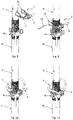
- each extremity (32) of the latch (3) comprises a protrusion (33) which can be hit upwards, as can be inferred by the position of the square face of the hammer shown in Figure 6 .
- this embodiment comprises a protrusion (20) which can be hit horizontally, as can be inferred by the position of the square face of the hammer shown in Figure 7 .
- the central section (31) of the latch (3) is affixed at a height that is slightly lower than the position of the extremities (32) resting on the inclined portions (23). This way, the latch (3) receives virtually no weight from the strut, due to which its rotation from the locking position to an unlocking position requires little effort from the operator.
- the ends of the base (2) can be previously separated from each other, as shown in Figure 8 .
- the extremities (23) of the base (2) can receive the connecting part (25), shown in Figure 9 , which closes the contour of the safety device (1) and prevents it from coming out of the strut.
- the operator can now insert the pin (P) through the corresponding slots and holes, as shown in Figure 10 , to finally place the latch (3) in its locking position, as shown in Figure 11 .
- the nut (N) can comprise a drive lever configured to thread the nut to the threaded portion of the outer tube (TE) when actuated by a user.
Landscapes
- Engineering & Computer Science (AREA)
- Architecture (AREA)
- Mechanical Engineering (AREA)
- Civil Engineering (AREA)
- Structural Engineering (AREA)
- Forms Removed On Construction Sites Or Auxiliary Members Thereof (AREA)
Claims (8)
- Sicherheitsvorrichtung (1, 1') für Streben, die angepasst ist, mit Streben des Typs verwendet zu werden, der ein äußeres Rohr (TE) mit einem oberen Gewindeabschnitt, der zwei längsverlaufende und diametral gegenüberliegende Schlitze umfasst, ein inneres Rohr (TI), das teleskopisch in das äußere Rohr (TE) aufgenommen ist und mindestens zwei diametral gegenüberliegende Löcher umfasst, eine Mutter (N), die auf den oberen Gewindeabschnitt des äußeren Rohrs (TE) geschraubt werden kann, sowie einen Bolzen (P), der sowohl in die beiden Schlitze des äußeren Rohrs (TE) als auch in die beiden Löcher des inneren Rohrs (TI) aufgenommen werden kann, umfasst, wobei die Sicherheitsvorrichtung (1, 1') für Streben eine Basis (2, 2') umfasst, die:- mindestens einen U-förmigen Abschnitt, der durch einen Mittenbereich (21) definiert ist, und Endpunkte (23) aufweist, wobei der Abstand zwischen mindestens einem Abschnitt der Endpunkte (22, 22') davon länger ist als die Breite des äußeren Rohrs (TE), während er kürzer als die Länge des Bolzens (P) und die Breite der Mutter (N) ist, und- in einem Verriegelungszustand der Sicherheitsvorrichtung (1, 1') für Streben angepasst ist, mit dem Abschnitt der Endpunkte (22, 22') davon um den oberen Gewindeabschnitt des äußeren Rohrs (TE) positioniert zu sein, während sie von der Mutter (N) gestützt wird, und wobei der Mittenabschnitt (21) der Basis (2, 2') vom äußeren Rohr (TE) getrennt ist,
wobei die Sicherheitsvorrichtung (1, 1') für Streben Folgendes aufweist- wobei die Oberfläche von jedem Endpunkt (22, 22') der Basis (2, 2') einen geneigten Abschnitt (23) umfasst, wobei beide geneigte Abschnitte (23) der Endpunkte (22, 22') relativ zur vertikalen Symmetrieebene der Basis (2, 2') symmetrisch zueinander sind und wobei sich die unteren Enden davon auf der Seite des Mittenbereichs (21) der Basis (2, 2') befinden, und dadurch gekennzeichnet, dass die Sicherheitsvorrichtung einen Riegel (3) umfasst, wobei mindestens ein U-förmiger Abschnitt in einer angelenkten Weise durch seinen Mittenbereich (31) am Mittenbereich (21) der Basis (2, 2') befestigt ist, der sich relativ zu einer Achse (A) senkrecht zur vertikalen Symmetrieebene der Basis (2, 2') frei drehen kann, der mindestens einen Vorsprung (33) aufweist, der in mindestens einem der Endpunkte (32) umfasst ist, wobei die Größe davon derart ist, dass die Endpunkte (32) davon in seinem Verriegelungszustand auf den geneigten Abschnitten (23) ruhen können. - Sicherheitsvorrichtung (1, 1') für Streben nach Anspruch 1, dadurch gekennzeichnet, dass der Mittenbereich (31) des Riegels (3) an der Basis (2, 2') in einer Höhe befestigt ist, die gleich oder tiefer ist als die Position der Endpunkte (32) davon, wenn sie auf den geneigten Abschnitten (23) ruhen.
- Sicherheitsvorrichtung (1, 1') für Streben nach einem der vorhergehenden Ansprüche, dadurch gekennzeichnet, dass sie Stufen umfasst, die die unteren Enden der geneigten Abschnitte (23) mit unteren Bereichen (24) der Oberfläche der Basis (2, 2') verbinden.
- Sicherheitsvorrichtung (1, 1') für Streben nach einem der vorhergehenden Ansprüche, dadurch gekennzeichnet, dass sie einen Vorsprung (20) im Mittenbereich (21) der Basis (2, 2') umfasst, der einen Stoß aufnehmen kann.
- Sicherheitsvorrichtung (1, 1') für Streben nach einem der vorhergehenden Ansprüche, dadurch gekennzeichnet, dass die geneigten Abschnitte (23) eine Oberfläche umfassen, die wärmebehandelt wurde, um gehärtet zu werden.
- Sicherheitsvorrichtung (1, 1') für Streben nach einem der vorhergehenden Ansprüche, dadurch gekennzeichnet, dass die Endpunkte (22, 22') der Basis (2, 2') durch Enden davon gekoppelt sind.
- Sicherheitsvorrichtung (1, 1') für Streben nach Anspruch 6, dadurch gekennzeichnet, dass sie ein Verbindungsstück (25) umfasst, das an beiden Endpunkten (22) der Basis (2) befestigt ist.
- Sicherheitsvorrichtung (1, 1') für Streben nach Anspruch 6, dadurch gekennzeichnet, dass die Basis (2') aus einem Stück besteht.
Priority Applications (2)
| Application Number | Priority Date | Filing Date | Title |
|---|---|---|---|
| EP19383096.5A EP3835513B1 (de) | 2019-12-11 | 2019-12-11 | Sicherheitsvorrichtung für stützen |
| PCT/ES2020/070762 WO2021116515A1 (es) | 2019-12-11 | 2020-12-02 | Recuperador de puntales |
Applications Claiming Priority (1)
| Application Number | Priority Date | Filing Date | Title |
|---|---|---|---|
| EP19383096.5A EP3835513B1 (de) | 2019-12-11 | 2019-12-11 | Sicherheitsvorrichtung für stützen |
Publications (2)
| Publication Number | Publication Date |
|---|---|
| EP3835513A1 EP3835513A1 (de) | 2021-06-16 |
| EP3835513B1 true EP3835513B1 (de) | 2022-08-31 |
Family
ID=69105709
Family Applications (1)
| Application Number | Title | Priority Date | Filing Date |
|---|---|---|---|
| EP19383096.5A Not-in-force EP3835513B1 (de) | 2019-12-11 | 2019-12-11 | Sicherheitsvorrichtung für stützen |
Country Status (2)
| Country | Link |
|---|---|
| EP (1) | EP3835513B1 (de) |
| WO (1) | WO2021116515A1 (de) |
Cited By (1)
| Publication number | Priority date | Publication date | Assignee | Title |
|---|---|---|---|---|
| AT528026B1 (de) * | 2024-07-30 | 2025-09-15 | Ringer Gmbh | Vorrichtung zum Abstützen einer Deckenschalung |
Family Cites Families (5)
| Publication number | Priority date | Publication date | Assignee | Title |
|---|---|---|---|---|
| DE3739754A1 (de) * | 1987-11-24 | 1989-06-08 | Mueller & Baum | Hoehenverstellbare stuetze fuer eine deckenschalung |
| DE4329910A1 (de) * | 1993-09-04 | 1995-03-09 | Mueller & Baum | Höhenverstellbare Stütze für eine Deckenschalung |
| FR2712017B1 (fr) | 1993-11-02 | 1996-01-12 | Rennepont | Dispositif de sécurité pour étais. |
| EP1975351B1 (de) | 2007-03-28 | 2011-08-17 | Mottura Serrature di Sicurezza S.p.A. | Zylinderschloss mit veränderbarer Schlüsselkombination |
| ES2366967T3 (es) * | 2007-03-29 | 2011-10-27 | Ulma C Y E, S. Coop. | Puntal con mecanismo de desencofrado. |
-
2019
- 2019-12-11 EP EP19383096.5A patent/EP3835513B1/de not_active Not-in-force
-
2020
- 2020-12-02 WO PCT/ES2020/070762 patent/WO2021116515A1/es not_active Ceased
Cited By (2)
| Publication number | Priority date | Publication date | Assignee | Title |
|---|---|---|---|---|
| AT528026B1 (de) * | 2024-07-30 | 2025-09-15 | Ringer Gmbh | Vorrichtung zum Abstützen einer Deckenschalung |
| AT528026A4 (de) * | 2024-07-30 | 2025-09-15 | Ringer Gmbh | Vorrichtung zum Abstützen einer Deckenschalung |
Also Published As
| Publication number | Publication date |
|---|---|
| WO2021116515A1 (es) | 2021-06-17 |
| EP3835513A1 (de) | 2021-06-16 |
Similar Documents
| Publication | Publication Date | Title |
|---|---|---|
| US4075913A (en) | Remotely operable mechanism for disconnecting a pickup unit from a tilt-up concrete wall slab | |
| US11306497B2 (en) | Support post | |
| JP4011021B2 (ja) | 伸縮梯子 | |
| US3424244A (en) | Collapsible support and assembly for casing or tubing liner or patch | |
| EP3825493A1 (de) | Fallschutzvorrichtung | |
| CN106661895A (zh) | 临时支撑和举升装置 | |
| EP0457377A1 (de) | Stahlrohrstütze für Bauschalungen | |
| EP3835513B1 (de) | Sicherheitsvorrichtung für stützen | |
| US5931258A (en) | Extendible safety posts for manhole ladders | |
| CN101243232A (zh) | 用于安全栅栏支柱的锁定和提升机构 | |
| US4187919A (en) | Cable-type core barrel | |
| CA2138795A1 (en) | Quick release washer for a shoring post | |
| JP3172713B2 (ja) | 伸縮体 | |
| CN111989446A (zh) | 支撑架构 | |
| US4262774A (en) | Adjustable scaffold | |
| EP0751338A1 (de) | Dreibeinstativ | |
| US1653126A (en) | Mine post or jack | |
| RU2379448C2 (ru) | Устройство для освобождения опорных элементов | |
| CN100432357C (zh) | 支柱 | |
| WO2003025311A1 (en) | Improvements in and relating to scaffolding | |
| EP1419989A2 (de) | Haken für Gitterträger | |
| CA1059782A (en) | Form removal device for use in scaffolding | |
| EP2808464A1 (de) | Gerüstturmanordnung und Verfahren zum Aufrichten eines Gerüstturms | |
| US4479522A (en) | Portable safety device for inflation of truck tires | |
| EP4555160A1 (de) | Vorrichtung zum formen/entformen von stützen für betondeckenschalungen |
Legal Events
| Date | Code | Title | Description |
|---|---|---|---|
| PUAI | Public reference made under article 153(3) epc to a published international application that has entered the european phase |
Free format text: ORIGINAL CODE: 0009012 |
|
| STAA | Information on the status of an ep patent application or granted ep patent |
Free format text: STATUS: THE APPLICATION HAS BEEN PUBLISHED |
|
| AK | Designated contracting states |
Kind code of ref document: A1 Designated state(s): AL AT BE BG CH CY CZ DE DK EE ES FI FR GB GR HR HU IE IS IT LI LT LU LV MC MK MT NL NO PL PT RO RS SE SI SK SM TR |
|
| STAA | Information on the status of an ep patent application or granted ep patent |
Free format text: STATUS: REQUEST FOR EXAMINATION WAS MADE |
|
| 17P | Request for examination filed |
Effective date: 20211001 |
|
| RBV | Designated contracting states (corrected) |
Designated state(s): AL AT BE BG CH CY CZ DE DK EE ES FI FR GB GR HR HU IE IS IT LI LT LU LV MC MK MT NL NO PL PT RO RS SE SI SK SM TR |
|
| GRAP | Despatch of communication of intention to grant a patent |
Free format text: ORIGINAL CODE: EPIDOSNIGR1 |
|
| STAA | Information on the status of an ep patent application or granted ep patent |
Free format text: STATUS: GRANT OF PATENT IS INTENDED |
|
| INTG | Intention to grant announced |
Effective date: 20220405 |
|
| GRAS | Grant fee paid |
Free format text: ORIGINAL CODE: EPIDOSNIGR3 |
|
| GRAA | (expected) grant |
Free format text: ORIGINAL CODE: 0009210 |
|
| STAA | Information on the status of an ep patent application or granted ep patent |
Free format text: STATUS: THE PATENT HAS BEEN GRANTED |
|
| AK | Designated contracting states |
Kind code of ref document: B1 Designated state(s): AL AT BE BG CH CY CZ DE DK EE ES FI FR GB GR HR HU IE IS IT LI LT LU LV MC MK MT NL NO PL PT RO RS SE SI SK SM TR |
|
| REG | Reference to a national code |
Ref country code: CH Ref legal event code: EP Ref country code: GB Ref legal event code: FG4D |
|
| REG | Reference to a national code |
Ref country code: AT Ref legal event code: REF Ref document number: 1515392 Country of ref document: AT Kind code of ref document: T Effective date: 20220915 Ref country code: DE Ref legal event code: R096 Ref document number: 602019018927 Country of ref document: DE |
|
| REG | Reference to a national code |
Ref country code: IE Ref legal event code: FG4D |
|
| REG | Reference to a national code |
Ref country code: LT Ref legal event code: MG9D |
|
| REG | Reference to a national code |
Ref country code: NL Ref legal event code: MP Effective date: 20220831 |
|
| PG25 | Lapsed in a contracting state [announced via postgrant information from national office to epo] |
Ref country code: SE Free format text: LAPSE BECAUSE OF FAILURE TO SUBMIT A TRANSLATION OF THE DESCRIPTION OR TO PAY THE FEE WITHIN THE PRESCRIBED TIME-LIMIT Effective date: 20220831 Ref country code: RS Free format text: LAPSE BECAUSE OF FAILURE TO SUBMIT A TRANSLATION OF THE DESCRIPTION OR TO PAY THE FEE WITHIN THE PRESCRIBED TIME-LIMIT Effective date: 20220831 Ref country code: NO Free format text: LAPSE BECAUSE OF FAILURE TO SUBMIT A TRANSLATION OF THE DESCRIPTION OR TO PAY THE FEE WITHIN THE PRESCRIBED TIME-LIMIT Effective date: 20221130 Ref country code: LV Free format text: LAPSE BECAUSE OF FAILURE TO SUBMIT A TRANSLATION OF THE DESCRIPTION OR TO PAY THE FEE WITHIN THE PRESCRIBED TIME-LIMIT Effective date: 20220831 Ref country code: LT Free format text: LAPSE BECAUSE OF FAILURE TO SUBMIT A TRANSLATION OF THE DESCRIPTION OR TO PAY THE FEE WITHIN THE PRESCRIBED TIME-LIMIT Effective date: 20220831 Ref country code: FI Free format text: LAPSE BECAUSE OF FAILURE TO SUBMIT A TRANSLATION OF THE DESCRIPTION OR TO PAY THE FEE WITHIN THE PRESCRIBED TIME-LIMIT Effective date: 20220831 |
|
| REG | Reference to a national code |
Ref country code: AT Ref legal event code: MK05 Ref document number: 1515392 Country of ref document: AT Kind code of ref document: T Effective date: 20220831 |
|
| PG25 | Lapsed in a contracting state [announced via postgrant information from national office to epo] |
Ref country code: PL Free format text: LAPSE BECAUSE OF FAILURE TO SUBMIT A TRANSLATION OF THE DESCRIPTION OR TO PAY THE FEE WITHIN THE PRESCRIBED TIME-LIMIT Effective date: 20220831 Ref country code: IS Free format text: LAPSE BECAUSE OF FAILURE TO SUBMIT A TRANSLATION OF THE DESCRIPTION OR TO PAY THE FEE WITHIN THE PRESCRIBED TIME-LIMIT Effective date: 20221231 Ref country code: HR Free format text: LAPSE BECAUSE OF FAILURE TO SUBMIT A TRANSLATION OF THE DESCRIPTION OR TO PAY THE FEE WITHIN THE PRESCRIBED TIME-LIMIT Effective date: 20220831 Ref country code: GR Free format text: LAPSE BECAUSE OF FAILURE TO SUBMIT A TRANSLATION OF THE DESCRIPTION OR TO PAY THE FEE WITHIN THE PRESCRIBED TIME-LIMIT Effective date: 20221201 |
|
| PG25 | Lapsed in a contracting state [announced via postgrant information from national office to epo] |
Ref country code: SM Free format text: LAPSE BECAUSE OF FAILURE TO SUBMIT A TRANSLATION OF THE DESCRIPTION OR TO PAY THE FEE WITHIN THE PRESCRIBED TIME-LIMIT Effective date: 20220831 Ref country code: RO Free format text: LAPSE BECAUSE OF FAILURE TO SUBMIT A TRANSLATION OF THE DESCRIPTION OR TO PAY THE FEE WITHIN THE PRESCRIBED TIME-LIMIT Effective date: 20220831 Ref country code: PT Free format text: LAPSE BECAUSE OF FAILURE TO SUBMIT A TRANSLATION OF THE DESCRIPTION OR TO PAY THE FEE WITHIN THE PRESCRIBED TIME-LIMIT Effective date: 20230102 Ref country code: ES Free format text: LAPSE BECAUSE OF FAILURE TO SUBMIT A TRANSLATION OF THE DESCRIPTION OR TO PAY THE FEE WITHIN THE PRESCRIBED TIME-LIMIT Effective date: 20220831 Ref country code: DK Free format text: LAPSE BECAUSE OF FAILURE TO SUBMIT A TRANSLATION OF THE DESCRIPTION OR TO PAY THE FEE WITHIN THE PRESCRIBED TIME-LIMIT Effective date: 20220831 Ref country code: CZ Free format text: LAPSE BECAUSE OF FAILURE TO SUBMIT A TRANSLATION OF THE DESCRIPTION OR TO PAY THE FEE WITHIN THE PRESCRIBED TIME-LIMIT Effective date: 20220831 Ref country code: AT Free format text: LAPSE BECAUSE OF FAILURE TO SUBMIT A TRANSLATION OF THE DESCRIPTION OR TO PAY THE FEE WITHIN THE PRESCRIBED TIME-LIMIT Effective date: 20220831 |
|
| PG25 | Lapsed in a contracting state [announced via postgrant information from national office to epo] |
Ref country code: SK Free format text: LAPSE BECAUSE OF FAILURE TO SUBMIT A TRANSLATION OF THE DESCRIPTION OR TO PAY THE FEE WITHIN THE PRESCRIBED TIME-LIMIT Effective date: 20220831 Ref country code: EE Free format text: LAPSE BECAUSE OF FAILURE TO SUBMIT A TRANSLATION OF THE DESCRIPTION OR TO PAY THE FEE WITHIN THE PRESCRIBED TIME-LIMIT Effective date: 20220831 |
|
| REG | Reference to a national code |
Ref country code: DE Ref legal event code: R097 Ref document number: 602019018927 Country of ref document: DE |
|
| PG25 | Lapsed in a contracting state [announced via postgrant information from national office to epo] |
Ref country code: NL Free format text: LAPSE BECAUSE OF FAILURE TO SUBMIT A TRANSLATION OF THE DESCRIPTION OR TO PAY THE FEE WITHIN THE PRESCRIBED TIME-LIMIT Effective date: 20220831 Ref country code: AL Free format text: LAPSE BECAUSE OF FAILURE TO SUBMIT A TRANSLATION OF THE DESCRIPTION OR TO PAY THE FEE WITHIN THE PRESCRIBED TIME-LIMIT Effective date: 20220831 |
|
| REG | Reference to a national code |
Ref country code: DE Ref legal event code: R119 Ref document number: 602019018927 Country of ref document: DE |
|
| PLBE | No opposition filed within time limit |
Free format text: ORIGINAL CODE: 0009261 |
|
| STAA | Information on the status of an ep patent application or granted ep patent |
Free format text: STATUS: NO OPPOSITION FILED WITHIN TIME LIMIT |
|
| REG | Reference to a national code |
Ref country code: CH Ref legal event code: PL |
|
| 26N | No opposition filed |
Effective date: 20230601 |
|
| REG | Reference to a national code |
Ref country code: BE Ref legal event code: MM Effective date: 20221231 |
|
| PG25 | Lapsed in a contracting state [announced via postgrant information from national office to epo] |
Ref country code: SI Free format text: LAPSE BECAUSE OF FAILURE TO SUBMIT A TRANSLATION OF THE DESCRIPTION OR TO PAY THE FEE WITHIN THE PRESCRIBED TIME-LIMIT Effective date: 20220831 Ref country code: LU Free format text: LAPSE BECAUSE OF NON-PAYMENT OF DUE FEES Effective date: 20221211 |
|
| PG25 | Lapsed in a contracting state [announced via postgrant information from national office to epo] |
Ref country code: LI Free format text: LAPSE BECAUSE OF NON-PAYMENT OF DUE FEES Effective date: 20221231 Ref country code: IE Free format text: LAPSE BECAUSE OF NON-PAYMENT OF DUE FEES Effective date: 20221211 Ref country code: DE Free format text: LAPSE BECAUSE OF NON-PAYMENT OF DUE FEES Effective date: 20230701 Ref country code: CH Free format text: LAPSE BECAUSE OF NON-PAYMENT OF DUE FEES Effective date: 20221231 |
|
| PG25 | Lapsed in a contracting state [announced via postgrant information from national office to epo] |
Ref country code: FR Free format text: LAPSE BECAUSE OF NON-PAYMENT OF DUE FEES Effective date: 20221231 Ref country code: BE Free format text: LAPSE BECAUSE OF NON-PAYMENT OF DUE FEES Effective date: 20221231 |
|
| PG25 | Lapsed in a contracting state [announced via postgrant information from national office to epo] |
Ref country code: CY Free format text: LAPSE BECAUSE OF FAILURE TO SUBMIT A TRANSLATION OF THE DESCRIPTION OR TO PAY THE FEE WITHIN THE PRESCRIBED TIME-LIMIT Effective date: 20220831 |
|
| PG25 | Lapsed in a contracting state [announced via postgrant information from national office to epo] |
Ref country code: MK Free format text: LAPSE BECAUSE OF FAILURE TO SUBMIT A TRANSLATION OF THE DESCRIPTION OR TO PAY THE FEE WITHIN THE PRESCRIBED TIME-LIMIT Effective date: 20220831 Ref country code: IT Free format text: LAPSE BECAUSE OF FAILURE TO SUBMIT A TRANSLATION OF THE DESCRIPTION OR TO PAY THE FEE WITHIN THE PRESCRIBED TIME-LIMIT Effective date: 20220831 Ref country code: HU Free format text: LAPSE BECAUSE OF FAILURE TO SUBMIT A TRANSLATION OF THE DESCRIPTION OR TO PAY THE FEE WITHIN THE PRESCRIBED TIME-LIMIT; INVALID AB INITIO Effective date: 20191211 |
|
| PG25 | Lapsed in a contracting state [announced via postgrant information from national office to epo] |
Ref country code: MC Free format text: LAPSE BECAUSE OF FAILURE TO SUBMIT A TRANSLATION OF THE DESCRIPTION OR TO PAY THE FEE WITHIN THE PRESCRIBED TIME-LIMIT Effective date: 20220831 |
|
| PG25 | Lapsed in a contracting state [announced via postgrant information from national office to epo] |
Ref country code: MC Free format text: LAPSE BECAUSE OF FAILURE TO SUBMIT A TRANSLATION OF THE DESCRIPTION OR TO PAY THE FEE WITHIN THE PRESCRIBED TIME-LIMIT Effective date: 20220831 |
|
| PG25 | Lapsed in a contracting state [announced via postgrant information from national office to epo] |
Ref country code: BG Free format text: LAPSE BECAUSE OF FAILURE TO SUBMIT A TRANSLATION OF THE DESCRIPTION OR TO PAY THE FEE WITHIN THE PRESCRIBED TIME-LIMIT Effective date: 20220831 |
|
| GBPC | Gb: european patent ceased through non-payment of renewal fee |
Effective date: 20231211 |
|
| PG25 | Lapsed in a contracting state [announced via postgrant information from national office to epo] |
Ref country code: MT Free format text: LAPSE BECAUSE OF FAILURE TO SUBMIT A TRANSLATION OF THE DESCRIPTION OR TO PAY THE FEE WITHIN THE PRESCRIBED TIME-LIMIT Effective date: 20220831 |
|
| PG25 | Lapsed in a contracting state [announced via postgrant information from national office to epo] |
Ref country code: GB Free format text: LAPSE BECAUSE OF NON-PAYMENT OF DUE FEES Effective date: 20231211 |
|
| PG25 | Lapsed in a contracting state [announced via postgrant information from national office to epo] |
Ref country code: GB Free format text: LAPSE BECAUSE OF NON-PAYMENT OF DUE FEES Effective date: 20231211 |
|
| PG25 | Lapsed in a contracting state [announced via postgrant information from national office to epo] |
Ref country code: TR Free format text: LAPSE BECAUSE OF FAILURE TO SUBMIT A TRANSLATION OF THE DESCRIPTION OR TO PAY THE FEE WITHIN THE PRESCRIBED TIME-LIMIT Effective date: 20220831 |