EP3835748B1 - Kontrollsystem mindestens einer komponente eines optischen elements - Google Patents
Kontrollsystem mindestens einer komponente eines optischen elements Download PDFInfo
- Publication number
- EP3835748B1 EP3835748B1 EP20213361.7A EP20213361A EP3835748B1 EP 3835748 B1 EP3835748 B1 EP 3835748B1 EP 20213361 A EP20213361 A EP 20213361A EP 3835748 B1 EP3835748 B1 EP 3835748B1
- Authority
- EP
- European Patent Office
- Prior art keywords
- image
- optical element
- luminous
- projected
- luminous image
- Prior art date
- Legal status (The legal status is an assumption and is not a legal conclusion. Google has not performed a legal analysis and makes no representation as to the accuracy of the status listed.)
- Active
Links
Images

Classifications
-
- G—PHYSICS
- G01—MEASURING; TESTING
- G01M—TESTING STATIC OR DYNAMIC BALANCE OF MACHINES OR STRUCTURES; TESTING OF STRUCTURES OR APPARATUS, NOT OTHERWISE PROVIDED FOR
- G01M11/00—Testing of optical apparatus; Testing structures by optical methods not otherwise provided for
- G01M11/02—Testing optical properties
- G01M11/0228—Testing optical properties by measuring refractive power
- G01M11/0235—Testing optical properties by measuring refractive power by measuring multiple properties of lenses, automatic lens meters
-
- G—PHYSICS
- G01—MEASURING; TESTING
- G01M—TESTING STATIC OR DYNAMIC BALANCE OF MACHINES OR STRUCTURES; TESTING OF STRUCTURES OR APPARATUS, NOT OTHERWISE PROVIDED FOR
- G01M11/00—Testing of optical apparatus; Testing structures by optical methods not otherwise provided for
- G01M11/02—Testing optical properties
- G01M11/0242—Testing optical properties by measuring geometrical properties or aberrations
- G01M11/0257—Testing optical properties by measuring geometrical properties or aberrations by analyzing the image formed by the object to be tested
- G01M11/0264—Testing optical properties by measuring geometrical properties or aberrations by analyzing the image formed by the object to be tested by using targets or reference patterns
-
- G—PHYSICS
- G01—MEASURING; TESTING
- G01M—TESTING STATIC OR DYNAMIC BALANCE OF MACHINES OR STRUCTURES; TESTING OF STRUCTURES OR APPARATUS, NOT OTHERWISE PROVIDED FOR
- G01M11/00—Testing of optical apparatus; Testing structures by optical methods not otherwise provided for
- G01M11/02—Testing optical properties
- G01M11/0242—Testing optical properties by measuring geometrical properties or aberrations
- G01M11/0278—Detecting defects of the object to be tested, e.g. scratches or dust
-
- G—PHYSICS
- G01—MEASURING; TESTING
- G01B—MEASURING LENGTH, THICKNESS OR SIMILAR LINEAR DIMENSIONS; MEASURING ANGLES; MEASURING AREAS; MEASURING IRREGULARITIES OF SURFACES OR CONTOURS
- G01B11/00—Measuring arrangements characterised by the use of optical techniques
- G01B11/24—Measuring arrangements characterised by the use of optical techniques for measuring contours or curvatures
- G01B11/25—Measuring arrangements characterised by the use of optical techniques for measuring contours or curvatures by projecting a pattern, e.g. one or more lines, moiré fringes on the object
-
- G—PHYSICS
- G01—MEASURING; TESTING
- G01N—INVESTIGATING OR ANALYSING MATERIALS BY DETERMINING THEIR CHEMICAL OR PHYSICAL PROPERTIES
- G01N21/00—Investigating or analysing materials by the use of optical means, i.e. using sub-millimetre waves, infrared, visible or ultraviolet light
- G01N21/84—Systems specially adapted for particular applications
- G01N21/88—Investigating the presence of flaws or contamination
- G01N21/8806—Specially adapted optical and illumination features
- G01N2021/8829—Shadow projection or structured background, e.g. for deflectometry
- G01N2021/8832—Structured background, e.g. for transparent objects
-
- G—PHYSICS
- G01—MEASURING; TESTING
- G01N—INVESTIGATING OR ANALYSING MATERIALS BY DETERMINING THEIR CHEMICAL OR PHYSICAL PROPERTIES
- G01N21/00—Investigating or analysing materials by the use of optical means, i.e. using sub-millimetre waves, infrared, visible or ultraviolet light
- G01N21/84—Systems specially adapted for particular applications
- G01N21/88—Investigating the presence of flaws or contamination
- G01N21/95—Investigating the presence of flaws or contamination characterised by the material or shape of the object to be examined
- G01N21/958—Inspecting transparent materials or objects, e.g. windscreens
Definitions
- the present invention relates to the field of devices for controlling optical components and more particularly to the field of devices for controlling ophthalmic components such as spectacle lenses or intraocular lenses.
- optical components The main function of optical components is to deflect incident light rays.
- the deflection of light through a component can be achieved in several directions or alternatively in a single direction and in a divergent, convergent or prismatic manner.
- the resulting image deformations are thus illustrations of spherical, cylindrical or prismatic components.
- some optical components are also capable of deformations corresponding to the combination of several of these different components.
- optical component deviations made by the optical component are characterized in particular by their optical powers, the optical power relating, on the one hand, to the vergence of a cylindrical or spherical component and, on the other hand, to the level of displacement of a prismatic component. Also, these optical powers form indices representative of the level of displacement and deformation of the image of an object through an optical component.
- optical components In the context of the production of optical components, particularly when these are intended to meet a minimum level of quality for an ophthalmic correction application, it is necessary to be able to effectively ensure their conformity with the properties required for the optical components produced, which includes compliance with the optical properties prescribed by the ophthalmologist, such as in particular the power and angle of the prismatic component, the power and angle of the main cylindrical component, and the power of the secondary cylindrical component, this secondary cylindrical component being orthogonal to the primary cylindrical component, but also the absence of defects such as scratches or machining traces.
- the optical properties prescribed by the ophthalmologist such as in particular the power and angle of the prismatic component, the power and angle of the main cylindrical component, and the power of the secondary cylindrical component, this secondary cylindrical component being orthogonal to the primary cylindrical component, but also the absence of defects such as scratches or machining traces.
- the present invention aims to overcome these drawbacks by proposing a solution for optimizing the verification of different optical properties of an optical or ophthalmic component and its qualities over the entire surface of the component while allowing verification in a wider power range.
- the invention thus relates to a system for controlling at least one component of an optical element as detailed by the statement of claim 1.
- the invention also relates to a method of control by implementing a control system of at least one component of an optical element as detailed by the statement of claim 7.
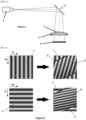
- the control system 1 of the invention is arranged to allow the implementation of an analysis of the deformation of an optical element 1 by comparing one or more elements of a projected image 7 with the corresponding elements of this same image after the latter has been deformed by the optical element 2.
- the image projected 7 by the projection device 4 of the invention comprises a periodic variation in light intensity. When the projected image 7 passes through the optical element 1, it undergoes a modification so that the corresponding image 8 having passed through the element optics 2 presents a variation in intensity shifted and/or distorted compared to that of the initial projected image 7.
- the calculation unit carries out a control of the optical element 2 by comparison between, on the one hand, the projected image 7 taken as reference, that is to say an image acquired by the acquisition device 5 and originating from the projected light image 7 without this image having passed through an optical element 2, and, on the other hand, an acquired light image which originates from the projected light image 7 and has passed through the optical element 2.
- the image used for determining the optical power of the controlled element 2 corresponds to a periodic variation in light intensity.
- the projected image 7 having by its dimensions a substantially rectangular shape, the periodic variation of light intensity is arranged along a first axis 9 of the plane of the image so that the image is presented in the form of a plurality of juxtaposed fringes, parallel to each other and oriented along a second axis 10 of the plane of the image, this second axis 10 being perpendicular to the first axis 9.
- a control system 1 which integrates a projected image 7 with an arrangement of juxtaposed fringes thus makes it possible to control the deformation produced by the optical element 2 in a full-field manner, that is to say simultaneously over the entire surface of the optical element 2.
- the parallel and juxtaposed rectilinear fringes of this projected image 7 thus make it possible to control the deformation produced by the optical element 2 according to a component perpendicular to the parallel axes 10 of the different rectilinear fringes.
- the use of a projected image 7 comprising a periodic variation in light intensity arranged according to parallel fringes makes it possible to identify and control a deformation carried out by the optical element 2 at each of the points of its surface and according to the same component, this component being perpendicular to the parallel axes 10 of the different rectilinear fringes of the image 7.
- the projection device 4 relates to a light display device such as a screen or a light display.
- This projection device 4 which is the light display device, makes it possible to carry out an analysis of the deformation of an optical element 1 from a projected image.
- This projected image corresponds to an image projected by diffusion from a screen.
- the calculation unit is configured to implement a processing of light images by comparing the position of at least two points of a projected light image 7, that is to say a light image acquired by the acquisition device without passing through the optical element 2 and therefore without deformation by the latter, with at least two points of the acquired light image 8 originating from the projected light image 7 and having passed through the optical element 2.
- the light image 7 used comprises a periodic variation in light intensity produced in the form of successive parallel fringes. The variation in intensity formed by these parallel juxtaposed fringes is thus oriented along an axis 9 perpendicular to the parallel axes 10 of the different rectilinear fringes.
- This orientation of the variation in light intensity thus defines the axis 9 of the component of the deformation of the optical element 2 according to which the control by the light image 7 is carried out.
- taking into account a single point of the projected light image 7 to be compared with a corresponding point of the acquired image having passed through the optical element 2 only allows the demonstration of a possible displacement of the image along the axis 9 of the control component that the orientation of the fringes of the projected image 7 allows, without however characterizing a deformation.
- taking into account at least two points makes it possible to calculate a deformation according to this same control component imposed by the orientation of the fringes of the projected image 7.
- the processing carried out by the calculation unit is based on taking into account, on the one hand, a first point of the projected light image 7 considered as a reference and, on the other hand, at least one second point whose position is defined relative to the first point.
- the displacement of these points between them at the level of the image 8 acquired after crossing the optical element 2 allows a characterization of the deformation that the optical element 2 produces on the projected image 7 along the axis 9 of the control component.
- the projected image 7 corresponds to a periodic variation in light intensity arranged according to parallel fringes, so that that the variation in light intensity is oriented along an axis 9 of the image plane perpendicular to the parallel axes 10 of each of the fringes of the image 7.
- a point of the image taken into consideration by the calculation unit of the system 1 of the invention is likely to correspond to a portion of the length of the same fringe of the projected image 7. Consequently, the projected image 7 does not make it possible to determine a possible displacement, nor a possible deformation along a direction parallel to the parallel axes 10 of each of the fringes of the image 7.
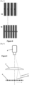
- At least the support device 3, the projection device 4 and the acquisition device 5 are mounted on the same frame.
- the arrangement of these three devices 3, 4, 5 mounted on a common frame makes it easier to move and install the entire control system 1.
- the installation on a common frame of these different devices 3, 4, 5 makes it possible to carry out a prior calibration and calibration of the control system 1 which makes it possible to dispense with these operations each time the control system 1 is used again.
- the system 1 comprises at least one reflection surface 11 positioned on the axis of the optical path of the light image 7 between the projection device 4 and the acquisition device 5.
- the use of one or more reflection surfaces 11 allows an adaptation of the spatial positioning of the different elements that are the support device 3, the projection device 4 and the acquisition device 5, so that the arrangement allows an optimized reduction of the size of the different devices 3, 4, 5 of the system 1.
- This reduction of the size of the control system 1 of the invention, in particular when the different devices 3, 4, 5 are mounted on a frame makes it easier to handle it during, for example, a move or an installation.
- At least one element from a list including the support device 3, the projection device 4, the acquisition device 5 and/or the reflection surface 11 is mounted movably relative to one or more other fixedly mounted elements of the system 1.
- This particular construction thus allows the performance of control operations at the level of several optical elements 2 successively positioned on the support device 3 on the axis of the optical path of the light image 7 between the projection device 4 and the acquisition device 5.
- the devices which have mobility are mounted to the structure of the frame by means of a movement interface such as, for example, a sliding rail.
- This mobility is also likely to be managed by a unit for calculating and/or controlling the movement of each of these devices 3, 4, 5, on the one hand, in relation to the structure of the frame which supports them and, on the other hand, in relation to the different devices mounted mobile between them.
- the support device 3 is mounted to be movable relative to the axis of the optical path of the light image between the projection device 4 and the acquisition device 5. Also, when the support device 3 is made, for example, in the form of a tray which carries a plurality of optical elements 2 to be analyzed, this support device 3 is arranged to be movable so as to allow its movement, for example by translation, so as to successively position each of the optical elements 2 on the axis of the optical path of the projected light image 7. The translation of the support device 3 is thus carried out at an identical position along the optical path.
- the acquisition device 5 is mounted to be mobile relative to the projection device 4 which remains fixed with the frame.
- the projection device 4 is then produced in the form of a luminous display device which has a surface sufficiently large to allow the projection of an image through a plurality of optical elements 2 to analyze carried by a support device 3 which has the shape of a tray.
- the acquisition device 5 is translated at a constant distance relative to the positioning plane of the optical elements 2 to be analyzed, or even relative to the plane of the projection device 4.
- the acquisition device 5 is positioned successively so as to align each optical element 2 on the axis of its optical acquisition path.
- the projection 4 and acquisition 5 devices are arranged in mobility so as to be moved, for example by translation, at a constant distance from the support device 3 which, in the form of a tray, carries a plurality of optical elements 2 to be analyzed. Also, the translation of the projection device 4 and of the acquisition device 5 is carried out so that the axis of the optical path of the projected light image 7 successively passes through each of the optical elements 2 carried by the support device 3. During the movement of the projection device 4 and of the acquisition device 5, the support device 3 and therefore the different optical elements 2 carried are positioned at an identical position along the optical path.
- the projection device 4 is configured to successively project at least two images 7, each image 7 corresponding to a variation in light intensity arranged according to fringes oriented along an axis 10 specific to each image 7. According to this particular example, at least two images are projected successively so that each of these projected images 7 allows control of the displacement and deformation carried out by the optical element 2 according to at least one respective component 9. Also, when the axes 10 of the parallel fringes of the images 7 have different orientations, the control of the displacement and deformation of the image carried out by the optical element 2 is carried out according to two different components.
- each of the images 7 by their variation of light intensity in the form of parallel fringes allowing a control of the displacement and the deformation at each of the points of the surface of the optical element 2, the combination of the components of displacement and deformation obtained thanks to the two successive images then authorizes a control of the displacement and deformation carried out by the optical element 2 at each of the points of its surface.
- the axes 10 of the parallel fringes of the images 7 have orientations orthogonal to each other so that the control of the displacement and deformation by the optical element 2 is carried out according to two orthogonal components.
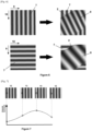
- the projection device 4 is configured to successively project at least two images 7, each image 7 having an identical variation in light intensity arranged according to fringes oriented along an identical axis 10, the variation in light intensity having a phase shift between the different images 7.
- the projection device 4 is configured to successively project a first series 12, 13, 14, 15 of four images 7, each image being formed by an identical variation in light intensity having a phase shift between each of these different images.
- a measurement of the light intensity is then carried out at at least one same position of each of the four acquired light images 8 from each of the four projected light images 7 of the first series and having passed through the optical element 2, so that, from the four light intensity values measured at the same position, the periodic light intensity variation curve of the projected light images 7 and having passed through the optical element 2 is able to be determined.
- the measurement of the light intensity at the level of at least one particular point of the acquired light image originating from a projected light image 12 originating from the first series and having passed through the optical element 2 makes it possible to identify, by phase correspondence, the location of each of the different points or fringes of this projected light image 12 originating from the first series and capable of corresponding to this at least one particular point of the acquired light image.
- the same operation is repeated from a second series of four images presenting an identical intensity variation with a phase shift between them, the wavelength of the variation in intensity of the images of this second series being different from that of the images of the first series, so that the measurement of the light intensity at the level of at least one particular point of an acquired light image originating from a projected light image 16 of the second series and having passed through the optical element 2 makes it possible to identify, by phase correspondence, the location of each of the points or fringes of this projected light image 16 of the second series capable of corresponding to this at least one particular point of the acquired light image.
- a comparison of the potential positions identified from each of the two projected light images 12, 16 originating respectively from the first series and the second series then allows an identification of the position according to a first component corresponding to the axis 9 of variation of light intensity of the projected images, of the point of any projected light image which corresponds to the particular point of the acquired light image.
- the combination of the components identified at a point of a projected light image corresponding to any point of the acquired light image 8 thus makes it possible to determine the coordinates of the position of this point on the surface of the projected light image.
- the step of comparing the position of at least two points of the second projected image with at least two points of the acquired light image 8 from the second projected light image 7 and having passed through the optical element 2 allows an evaluation of the deformation and/or the displacement operated by the optical element 2.
- the second image corresponds to a variation in light intensity having a phase shift relative to that of the previously projected image
- the variation in intensity being arranged according to fringes oriented along an axis 10 identical to that of the similar image previously projected
- the phase shift of the variation in intensity between the similar projected images makes it possible to determine the curve of periodic variation in light intensity of the light images in order to identify the different points of the projected light image likely to correspond to a particular point of the acquired light image whose position is defined.
- the difference in wavelength in the variation in light intensity between the projected images allows identification of the point of the projected light image whose component along the axis 9 of the variation in intensity corresponds to that of a particular point of the acquired light image whose position is defined.
- the present invention relates to devices for controlling optical components, in particular ophthalmic components, such as spectacle lenses or intraocular lenses.
- optical components in particular ophthalmic components, such as spectacle lenses or intraocular lenses.
- the purpose of this control is to characterize on the one hand the optical properties, in particular the local or global optical powers of the component, and on the other hand the cosmetic defects of various kinds.
- Such an architecture makes it possible to meet the initial objective: a measurement of local or global optical powers, and a detection of cosmetic defects.
- the application of commonly practiced deflectometry consists of observing the image, through the optical component to be controlled, of a series of sinusoidal fringes oriented in one direction, then of a second series of fringes oriented in a direction orthogonal to the first.
- This technique in the context of measuring the power of optical components, can be used in two ways:
- Magnification measurement via the spatial frequency of fringe images this amounts to measuring the deformation of an object.
- the data processing algorithm in the invention differs from that of the state of the art. However, this method does not allow the prismatic component of optical power to be measured. Reconstruction of optical paths by identifying the position of the emitting point. This method requires more detailed calibration, but allows the measurement of the prismatic component of the optical power
- the data processing algorithm in the context of the invention differs from that of the state of the art.
- deflectometry in the measurement of optical components, particularly ophthalmic components, allows very quickly and very inexpensively to control all the characteristics of these components: their optical power (global and/or local) and their possible cosmetic defects. This advantage cannot be obtained by other technologies, except by combining them with an additional sensor.
Landscapes
- Physics & Mathematics (AREA)
- Chemical & Material Sciences (AREA)
- Analytical Chemistry (AREA)
- General Physics & Mathematics (AREA)
- Geometry (AREA)
- Transforming Electric Information Into Light Information (AREA)
Claims (9)
- System zur Kontrolle (1) mindestens einer Komponente eines optischen Elements (2), wobei das System (1) mindestens umfasst:- eine Trägervorrichtung (3) für mindestens ein zu kontrollierendes optisches Element (2),- eine Projektionsvorrichtung (4), wie etwa einen Bildschirm oder ein Display, zum Projizieren mindestens eines Lichtbilds auf ein zu kontrollierendes optisches Element (2), wobei das Lichtbild ein definiertes Schema beinhaltet,- eine Erfassungsvorrichtung (5) zur Erfassung mindestens eines Teils des Lichtbilds, der das zu kontrollierende optische Element (2) durchquert hat und aus dem projizierten Lichtbild stammt, wobei der Sichtraumwinkel (6) der Erfassungsvorrichtung (5) die Trägervorrichtung (3) umfasst, die dem zu kontrollierenden optischen Element (2) zugeordnet ist,dadurch gekennzeichnet, dass das System ferner umfasst:- eine Recheneinheit, die dazu ausgestaltet ist, die optische Leistung des kontrollierten Elements (2) anhand, zum einen, von mindestens zwei Punkten mindestens eines projizierten Lichtbilds (7) das von der Erfassungsvorrichtung (5) erfasst wird, ohne das optische Element (2) zu passieren und, zum anderen, von mindestens zwei Punkten des erfassten Lichtbilds (8), das aus dem projizierten Lichtbild (7) stammt und das optische Element (2) durchquert hat, zu bestimmen,wobei die Projektionsvorrichtung (4) dazu ausgestaltet ist, nacheinander mindestens zwei Bilder (7) zu projizieren, wobei jedes Bild (7) einer periodischen Lichtintensitätsänderung entspricht, die gemäß parallelen und gemäß einer identischen Achse (10) ausgerichteten Streifen angeordnet ist, wobei die Lichtintensitätsänderung des projizierten zweiten Bilds eine Wellenlänge aufweist, die verschieden von der des zuvor projizierten ersten Bilds ist.
- System zur Kontrolle (1) nach Anspruch 1, dadurch gekennzeichnet, dass mindestens die Trägervorrichtung (3), die Projektionsvorrichtung (4) und die Erfassungsvorrichtung (5) an einem selben Gestell montiert sind.
- System zur Kontrolle (1) nach einem der vorhergehenden Ansprüche, dadurch gekennzeichnet, dass das System (1) mindestens eine Reflexionsfläche (11) umfasst, die auf der Achse des optischen Pfads des Lichtbilds (7) zwischen der Projektionsvorrichtung (4) und der Erfassungsvorrichtung (5) positioniert ist.
- System zur Kontrolle (1) nach einem der vorhergehenden Ansprüche, dadurch gekennzeichnet, dass mindestens ein Element aus einer Liste, die die Trägervorrichtung (3), die Projektionsvorrichtung (4), die Erfassungsvorrichtung (5) und/oder die Reflexionsfläche (11) enthält, in Bezug auf ein oder mehrere andere Elemente des Systems (1), die ortsfest montiert sind, beweglich montiert ist.
- System zur Kontrolle (1) nach Anspruch 4, dadurch gekennzeichnet, dass die Trägervorrichtung (3) in Bezug auf die Achse des optischen Pfads des Lichtbilds zwischen der Projektionsvorrichtung (4) und der Erfassungsvorrichtung (5) beweglich montiert ist.
- System zur Kontrolle (1) nach einem der vorhergehenden Ansprüche, dadurch gekennzeichnet, dass die Recheneinheit dazu ausgestaltet ist, eine Verarbeitung von Lichtbildern durch Vergleichen der Position von mindestens zwei Punkten eines projizierten Lichtbilds (7) mit mindestens zwei Punkten des erfassten Lichtbilds (8), das aus dem projizierten Lichtbild (7) stammt und das optische Element durchquert hat, zu implementieren.
- Verfahren zur Kontrolle durch Implementieren eines Systems zur Kontrolle (1) mindestens einer Komponente eines optischen Elements (2), umfassend:- eine Projektionsvorrichtung (4), wie etwa einen Bildschirm oder ein Display, zum Projizieren mindestens eines Lichtbilds auf ein zu kontrollierendes optisches Element (2),- eine Erfassungsvorrichtung (5) zur Erfassung mindestens eines Teils des Lichtbilds, der das zu kontrollierende optische Element (2) durchquert hat und aus dem projizierten Lichtbild (7) stammt,das Verfahren umfassend mindestens:- einen Schritt des Positionierens eines zu kontrollierenden optischen Elements (2),- einen Schritt des Projizierens eines Lichtbilds (7) auf mindestens einen Teil der Fläche des zu kontrollierenden optischen Elements (2), wobei das Bild einer periodischen Lichtintensitätsänderung entspricht, die gemäß parallelen und gemäß einer definierten Achse (9) ausgerichteten Streifen angeordnet ist,- einen Schritt des Erfassens mindestens eines Teils des Lichtbilds (8), der das zu kontrollierende optische Element (2) durchquert hat und aus dem projizierten Lichtbild (7) stammt,dadurch gekennzeichnet, dass das Verfahren umfasst:- einen Schritt des Vergleichens der Position von mindestens zwei Punkten des projizierten ersten Lichtbilds (7), das von der Erfassungsvorrichtung erfasst wird, ohne das optische Element zu durchqueren, mit der Position von mindestens zwei Punkten des erfassten Lichtbilds (8), das aus dem projizierten ersten Lichtbild (7) stammt und das optische Element (2) durchquert hat,- einen Schritt des Projizierens eines neuen Lichtbilds (7) auf mindestens einen Teil der Fläche des zu kontrollierenden optischen Elements (2), wobei das neue Bild einer Lichtintensitätsänderung entspricht, die gemäß Streifen angeordnet ist, die gemäß einer Achse (10) ausgerichtet sind, die identisch mit der des zuvor projizierten ersten Bilds ist, wobei die Lichtintensitätsänderung eine Wellenlänge aufweist, die verschieden von der des zuvor projizierten ersten Bilds ist,- einen Schritt des Erfassens mindestens eines Teils des Lichtbilds (8), der das zu kontrollierende optische Element (2) durchquert hat und aus dem projizierten neuen Lichtbild (7) stammt,- einen Schritt des Vergleichens der Lichtintensität mindestens eines Punkts des projizierten neuen Lichtbilds (7), das von der Erfassungsvorrichtung erfasst wird, ohne das optische Element zu durchqueren, mit mindestens einem Punkt des erfassten Lichtbilds (8), das aus dem projizierten neuen Lichtbild (7) stammt und das optische Element (2) durchquert hat,- einen Schritt des Bestimmens mindestens einer Komponente, entsprechend der Achse (9) der Lichtintensitätsänderung, der Position des Punkts des projizierten Lichtbilds (7), entsprechend dem mindestens einen Punkt einer ermittelten Position eines erfassten Lichtbilds (8), das aus einem projizierten Lichtbild (7) stammt und das optische Element (2) durchquert hat,- einen Schritt des Bestimmens der Vergrößerung oder prismatischen Verlagerung des optischen Elements (2) gemäß der Achse (9) der Lichtintensitätsänderung des Bilds (7), beruhend auf dem Schritt des Vergleichens der Lichtintensität zwischen zwei mindestens einem Punkt,- einen Schritt des Evaluierens der optischen Leistung des optischen Elements (2) gemäß der Achse (9) der Lichtintensitätsänderung des Bilds (7) anhand seiner Vergrößerung oder prismatischen Verlagerung.
- Verfahren zur Kontrolle nach Anspruch 7, dadurch gekennzeichnet, dass das Verfahren ferner umfasst:- einen Schritt des Projizierens eines zweiten Lichtbilds (7) auf mindestens einen Teil der Fläche des zu kontrollierenden optischen Elements (2), wobei das zweite Bild einer periodischen Lichtintensitätsänderung entspricht, die gemäß parallelen und gemäß einer zweiten Achse (9) ausgerichteten Streifen angeordnet ist, wobei die zweite Achse (9) die Achse (9) eines zuvor projizierten ähnlichen Bilds schneidet,- einen Schritt des Erfassens mindestens eines Teils des Lichtbilds 8, der das zu kontrollierende optische Element (2) durchquert hat und aus dem projizierten zweiten Lichtbild (7) stammt,- einen Schritt des Vergleichens der Position von mindestens zwei Punkten des projizierten zweiten Lichtbilds (7) mit mindestens zwei Punkten des erfassten Lichtbilds (8), das aus dem projizierten zweiten Lichtbild (7) stammt und das optische Element (2) durchquert hat,- einen Schritt des Bestimmens der Vergrößerung oder prismatischen Verlagerung des optischen Elements (2) gemäß der Achse (9) der Lichtintensitätsänderung des zweiten Bilds (7),- einen Schritt des Evaluierens der optischen Leistung des optischen Elements (2) anhand der Vergrößerungen oder prismatischen Verlagerungen, die mindestens gemäß den Lichtintensitätsänderungen des ersten Bilds und des zweiten Bilds bestimmt werden.
- Verfahren zur Kontrolle nach einem der Ansprüche 7 oder 8, dadurch gekennzeichnet, dass das Verfahren ferner umfasst:- einen Schritt des Projizierens eines neuen Lichtbilds (7) auf mindestens einen Teil der Fläche des zu kontrollierenden optischen Elements (2), wobei das neue Bild einer Lichtintensitätsänderung entspricht, die identisch mit der des zuvor projizierten ähnlichen Bilds ist, wobei die Intensitätsänderung gemäß Streifen angeordnet ist, die gemäß einer Achse (10) ausgerichtet sind, die identisch mit der des zuvor projizierten ähnlichen Bilds ist, wobei die Lichtintensitätsänderung eine Phasenverschiebung in Bezug auf die des zuvor projizierten ähnlichen Bilds aufweist,- einen Schritt des Erfassens mindestens eines Teils des Lichtbilds (8), der das zu kontrollierende optische Element (2) durchquert hat und aus dem projizierten neuen Lichtbild (7) stammt,- einen Schritt des Vergleichens der Lichtintensität mindestens eines Punkts des projizierten neuen Lichtbilds (7) mit mindestens einem Punkt des erfassten Lichtbilds (8), das aus dem projizierten neuen Lichtbild (7) stammt und das optische Element (2) durchquert hat,- einen Schritt des Bestimmens mindestens einer Komponente der Position des Punkts des projizierten Lichtbilds (7), entsprechend dem mindestens einen Punkt einer ermittelten Position eines erfassten Lichtbilds (8), das aus einem projizierten Lichtbild (7) stammt und das optische Element (2) durchquert hat.
Applications Claiming Priority (2)
| Application Number | Priority Date | Filing Date | Title |
|---|---|---|---|
| FR1914420A FR3104700A1 (fr) | 2019-12-13 | 2019-12-13 | Contrôle de lentilles ophtalmiques par déflectométrie |
| FR2000271A FR3104699B1 (fr) | 2019-12-13 | 2020-01-13 | Système de contrôle d’au moins un composant d’un élément optique |
Publications (2)
| Publication Number | Publication Date |
|---|---|
| EP3835748A1 EP3835748A1 (de) | 2021-06-16 |
| EP3835748B1 true EP3835748B1 (de) | 2025-04-09 |
Family
ID=73726757
Family Applications (1)
| Application Number | Title | Priority Date | Filing Date |
|---|---|---|---|
| EP20213361.7A Active EP3835748B1 (de) | 2019-12-13 | 2020-12-11 | Kontrollsystem mindestens einer komponente eines optischen elements |
Country Status (1)
| Country | Link |
|---|---|
| EP (1) | EP3835748B1 (de) |
Families Citing this family (1)
| Publication number | Priority date | Publication date | Assignee | Title |
|---|---|---|---|---|
| DE102022200614A1 (de) * | 2022-01-20 | 2023-07-20 | Rodenstock Gmbh | Vorrichtung zur Untersuchung eines transparenten Werkstückes sowie die Verwendung einer solchen Vorrichtung als telezentrisches Messystem in Transmission |
Family Cites Families (4)
| Publication number | Priority date | Publication date | Assignee | Title |
|---|---|---|---|---|
| US6208412B1 (en) * | 1999-06-14 | 2001-03-27 | Visteon Global Technologies, Inc. | Method and apparatus for determining optical quality |
| EP1980843A1 (de) * | 2007-04-13 | 2008-10-15 | Essilor International (Compagnie Generale D'optique) | Verfahren und Vorrichtung zur Schadensdetektion bei optischen Komponenten |
| WO2018073577A2 (en) * | 2016-10-18 | 2018-04-26 | Aston Eyetech Limited | Lens examination equipment and method |
| US10321820B1 (en) * | 2017-12-21 | 2019-06-18 | Facebook Technologies, Llc | Measuring optical properties of an eyewear device |
-
2020
- 2020-12-11 EP EP20213361.7A patent/EP3835748B1/de active Active
Also Published As
| Publication number | Publication date |
|---|---|
| EP3835748A1 (de) | 2021-06-16 |
Similar Documents
| Publication | Publication Date | Title |
|---|---|---|
| US11294161B2 (en) | 3D microscope including insertable components to provide multiple imaging and measurement capabilities | |
| EP0644411B1 (de) | Verfahren und Gerät zur absoluten Messung der geometrischen oder optischen Struktur eines optischen Bestandteiles | |
| US20140268105A1 (en) | Optical defect inspection system | |
| FR2725532A1 (fr) | Microscope autofocus | |
| WO2011117539A1 (fr) | Methode et installation pour detecter la presence et l'altitude de defauts dans un composant optique | |
| FR2869408A1 (fr) | Procede et dispositif pour determiner la forme et les normales locales de surfaces reflechissantes | |
| EP1771714B1 (de) | Verfahren zur Prüfung einer optischen Komponente der ophthalmischen Industrie | |
| EP3069185B1 (de) | Dreidimensionale fokussierungsvorrichtung und verfahren für ein mikroskop | |
| WO2020178234A1 (fr) | Procede et dispositif de mesure d'interfaces d'un element optique | |
| WO2009112704A1 (fr) | Dispositif d'inspection de plaquettes semi-conductrices | |
| US10429319B2 (en) | Inspection system including parallel imaging paths with multiple and selectable spectral bands | |
| US10598604B1 (en) | Normal incidence phase-shifted deflectometry sensor, system, and method for inspecting a surface of a specimen | |
| EP3835748B1 (de) | Kontrollsystem mindestens einer komponente eines optischen elements | |
| FR3104699A1 (fr) | Système de contrôle d’au moins un composant d’un élément optique | |
| EP4505156A1 (de) | Verfahren und system zur charakterisierung einer optischen linse zur korrektur von durch die optische linse in ein bild eingeführten optischen aberrationen | |
| FR3050528A1 (fr) | Procede et dispositif d’estimation de proprietes optiques d’un echantillon | |
| CA2864866C (fr) | Procede et appareil de mesure de la structure geometrique d'un composant optique | |
| FR3100331A1 (fr) | Procede et systeme de test pour l’evaluation de la qualite d'une unite de projection micro-optique et/ou de projection optique sub-longueur d’onde a canaux multiples | |
| JP6344898B2 (ja) | 欠陥および特徴的形状を検出する装置 | |
| FR3141243A1 (fr) | Procédé de caractérisation fonctionnelle d’objectifs optiques de Smartphone | |
| FR3102845A1 (fr) | Détermination d'au moins un paramètre optique d'une lentille optique | |
| CN113176076A (zh) | 光学检测系统及光学检测方法 | |
| US8902429B1 (en) | Focusing detector of an interferometry system | |
| EP0053992A1 (de) | Verfahren und Einrichtung zur optischen Kontrolle der Oberflächenzustände von Metallgütern | |
| Martinez | 3D optical profilometry measurements of colloidal quantum dot devices |
Legal Events
| Date | Code | Title | Description |
|---|---|---|---|
| PUAI | Public reference made under article 153(3) epc to a published international application that has entered the european phase |
Free format text: ORIGINAL CODE: 0009012 |
|
| STAA | Information on the status of an ep patent application or granted ep patent |
Free format text: STATUS: THE APPLICATION HAS BEEN PUBLISHED |
|
| AK | Designated contracting states |
Kind code of ref document: A1 Designated state(s): AL AT BE BG CH CY CZ DE DK EE ES FI FR GB GR HR HU IE IS IT LI LT LU LV MC MK MT NL NO PL PT RO RS SE SI SK SM TR |
|
| STAA | Information on the status of an ep patent application or granted ep patent |
Free format text: STATUS: REQUEST FOR EXAMINATION WAS MADE |
|
| 17P | Request for examination filed |
Effective date: 20211207 |
|
| RBV | Designated contracting states (corrected) |
Designated state(s): AL AT BE BG CH CY CZ DE DK EE ES FI FR GB GR HR HU IE IS IT LI LT LU LV MC MK MT NL NO PL PT RO RS SE SI SK SM TR |
|
| GRAP | Despatch of communication of intention to grant a patent |
Free format text: ORIGINAL CODE: EPIDOSNIGR1 |
|
| STAA | Information on the status of an ep patent application or granted ep patent |
Free format text: STATUS: GRANT OF PATENT IS INTENDED |
|
| RIC1 | Information provided on ipc code assigned before grant |
Ipc: G01N 21/958 20060101ALI20231123BHEP Ipc: G01B 11/25 20060101ALI20231123BHEP Ipc: G01N 21/88 20060101ALI20231123BHEP Ipc: G01M 11/02 20060101AFI20231123BHEP |
|
| INTG | Intention to grant announced |
Effective date: 20231211 |
|
| GRAJ | Information related to disapproval of communication of intention to grant by the applicant or resumption of examination proceedings by the epo deleted |
Free format text: ORIGINAL CODE: EPIDOSDIGR1 |
|
| STAA | Information on the status of an ep patent application or granted ep patent |
Free format text: STATUS: REQUEST FOR EXAMINATION WAS MADE |
|
| GRAS | Grant fee paid |
Free format text: ORIGINAL CODE: EPIDOSNIGR3 |
|
| INTC | Intention to grant announced (deleted) | ||
| RAP3 | Party data changed (applicant data changed or rights of an application transferred) |
Owner name: V-OPTICS |
|
| STAA | Information on the status of an ep patent application or granted ep patent |
Free format text: STATUS: GRANT OF PATENT IS INTENDED |
|
| GRAP | Despatch of communication of intention to grant a patent |
Free format text: ORIGINAL CODE: EPIDOSNIGR1 |
|
| INTG | Intention to grant announced |
Effective date: 20240524 |
|
| GRAJ | Information related to disapproval of communication of intention to grant by the applicant or resumption of examination proceedings by the epo deleted |
Free format text: ORIGINAL CODE: EPIDOSDIGR1 |
|
| GRAL | Information related to payment of fee for publishing/printing deleted |
Free format text: ORIGINAL CODE: EPIDOSDIGR3 |
|
| STAA | Information on the status of an ep patent application or granted ep patent |
Free format text: STATUS: REQUEST FOR EXAMINATION WAS MADE |
|
| INTC | Intention to grant announced (deleted) | ||
| GRAP | Despatch of communication of intention to grant a patent |
Free format text: ORIGINAL CODE: EPIDOSNIGR1 |
|
| STAA | Information on the status of an ep patent application or granted ep patent |
Free format text: STATUS: GRANT OF PATENT IS INTENDED |
|
| INTG | Intention to grant announced |
Effective date: 20241105 |
|
| GRAA | (expected) grant |
Free format text: ORIGINAL CODE: 0009210 |
|
| STAA | Information on the status of an ep patent application or granted ep patent |
Free format text: STATUS: THE PATENT HAS BEEN GRANTED |
|
| AK | Designated contracting states |
Kind code of ref document: B1 Designated state(s): AL AT BE BG CH CY CZ DE DK EE ES FI FR GB GR HR HU IE IS IT LI LT LU LV MC MK MT NL NO PL PT RO RS SE SI SK SM TR |
|
| REG | Reference to a national code |
Ref country code: GB Ref legal event code: FG4D Free format text: NOT ENGLISH |
|
| REG | Reference to a national code |
Ref country code: CH Ref legal event code: EP |
|
| REG | Reference to a national code |
Ref country code: DE Ref legal event code: R096 Ref document number: 602020049026 Country of ref document: DE |
|
| REG | Reference to a national code |
Ref country code: IE Ref legal event code: FG4D Free format text: LANGUAGE OF EP DOCUMENT: FRENCH |
|
| REG | Reference to a national code |
Ref country code: NL Ref legal event code: MP Effective date: 20250409 |
|
| PG25 | Lapsed in a contracting state [announced via postgrant information from national office to epo] |
Ref country code: NL Free format text: LAPSE BECAUSE OF FAILURE TO SUBMIT A TRANSLATION OF THE DESCRIPTION OR TO PAY THE FEE WITHIN THE PRESCRIBED TIME-LIMIT Effective date: 20250409 |
|
| REG | Reference to a national code |
Ref country code: AT Ref legal event code: MK05 Ref document number: 1783911 Country of ref document: AT Kind code of ref document: T Effective date: 20250409 |
|
| PG25 | Lapsed in a contracting state [announced via postgrant information from national office to epo] |
Ref country code: FI Free format text: LAPSE BECAUSE OF FAILURE TO SUBMIT A TRANSLATION OF THE DESCRIPTION OR TO PAY THE FEE WITHIN THE PRESCRIBED TIME-LIMIT Effective date: 20250409 Ref country code: PT Free format text: LAPSE BECAUSE OF FAILURE TO SUBMIT A TRANSLATION OF THE DESCRIPTION OR TO PAY THE FEE WITHIN THE PRESCRIBED TIME-LIMIT Effective date: 20250811 Ref country code: ES Free format text: LAPSE BECAUSE OF FAILURE TO SUBMIT A TRANSLATION OF THE DESCRIPTION OR TO PAY THE FEE WITHIN THE PRESCRIBED TIME-LIMIT Effective date: 20250409 |
|
| REG | Reference to a national code |
Ref country code: LT Ref legal event code: MG9D |
|
| PG25 | Lapsed in a contracting state [announced via postgrant information from national office to epo] |
Ref country code: NO Free format text: LAPSE BECAUSE OF FAILURE TO SUBMIT A TRANSLATION OF THE DESCRIPTION OR TO PAY THE FEE WITHIN THE PRESCRIBED TIME-LIMIT Effective date: 20250709 Ref country code: GR Free format text: LAPSE BECAUSE OF FAILURE TO SUBMIT A TRANSLATION OF THE DESCRIPTION OR TO PAY THE FEE WITHIN THE PRESCRIBED TIME-LIMIT Effective date: 20250710 |
|
| PG25 | Lapsed in a contracting state [announced via postgrant information from national office to epo] |
Ref country code: PL Free format text: LAPSE BECAUSE OF FAILURE TO SUBMIT A TRANSLATION OF THE DESCRIPTION OR TO PAY THE FEE WITHIN THE PRESCRIBED TIME-LIMIT Effective date: 20250409 |
|
| PG25 | Lapsed in a contracting state [announced via postgrant information from national office to epo] |
Ref country code: BG Free format text: LAPSE BECAUSE OF FAILURE TO SUBMIT A TRANSLATION OF THE DESCRIPTION OR TO PAY THE FEE WITHIN THE PRESCRIBED TIME-LIMIT Effective date: 20250409 |
|
| PG25 | Lapsed in a contracting state [announced via postgrant information from national office to epo] |
Ref country code: HR Free format text: LAPSE BECAUSE OF FAILURE TO SUBMIT A TRANSLATION OF THE DESCRIPTION OR TO PAY THE FEE WITHIN THE PRESCRIBED TIME-LIMIT Effective date: 20250409 |
|
| PG25 | Lapsed in a contracting state [announced via postgrant information from national office to epo] |
Ref country code: AT Free format text: LAPSE BECAUSE OF FAILURE TO SUBMIT A TRANSLATION OF THE DESCRIPTION OR TO PAY THE FEE WITHIN THE PRESCRIBED TIME-LIMIT Effective date: 20250409 |
|
| PG25 | Lapsed in a contracting state [announced via postgrant information from national office to epo] |
Ref country code: RS Free format text: LAPSE BECAUSE OF FAILURE TO SUBMIT A TRANSLATION OF THE DESCRIPTION OR TO PAY THE FEE WITHIN THE PRESCRIBED TIME-LIMIT Effective date: 20250709 |
|
| PG25 | Lapsed in a contracting state [announced via postgrant information from national office to epo] |
Ref country code: IS Free format text: LAPSE BECAUSE OF FAILURE TO SUBMIT A TRANSLATION OF THE DESCRIPTION OR TO PAY THE FEE WITHIN THE PRESCRIBED TIME-LIMIT Effective date: 20250809 |
|
| PG25 | Lapsed in a contracting state [announced via postgrant information from national office to epo] |
Ref country code: LV Free format text: LAPSE BECAUSE OF FAILURE TO SUBMIT A TRANSLATION OF THE DESCRIPTION OR TO PAY THE FEE WITHIN THE PRESCRIBED TIME-LIMIT Effective date: 20250409 |
|
| REG | Reference to a national code |
Ref country code: DE Ref legal event code: R097 Ref document number: 602020049026 Country of ref document: DE |
|
| PG25 | Lapsed in a contracting state [announced via postgrant information from national office to epo] |
Ref country code: DK Free format text: LAPSE BECAUSE OF FAILURE TO SUBMIT A TRANSLATION OF THE DESCRIPTION OR TO PAY THE FEE WITHIN THE PRESCRIBED TIME-LIMIT Effective date: 20250409 Ref country code: SM Free format text: LAPSE BECAUSE OF FAILURE TO SUBMIT A TRANSLATION OF THE DESCRIPTION OR TO PAY THE FEE WITHIN THE PRESCRIBED TIME-LIMIT Effective date: 20250409 |
|
| PGFP | Annual fee paid to national office [announced via postgrant information from national office to epo] |
Ref country code: FR Payment date: 20251229 Year of fee payment: 6 |
|
| PG25 | Lapsed in a contracting state [announced via postgrant information from national office to epo] |
Ref country code: CZ Free format text: LAPSE BECAUSE OF FAILURE TO SUBMIT A TRANSLATION OF THE DESCRIPTION OR TO PAY THE FEE WITHIN THE PRESCRIBED TIME-LIMIT Effective date: 20250409 |
|
| PG25 | Lapsed in a contracting state [announced via postgrant information from national office to epo] |
Ref country code: EE Free format text: LAPSE BECAUSE OF FAILURE TO SUBMIT A TRANSLATION OF THE DESCRIPTION OR TO PAY THE FEE WITHIN THE PRESCRIBED TIME-LIMIT Effective date: 20250409 |
|
| PG25 | Lapsed in a contracting state [announced via postgrant information from national office to epo] |
Ref country code: RO Free format text: LAPSE BECAUSE OF FAILURE TO SUBMIT A TRANSLATION OF THE DESCRIPTION OR TO PAY THE FEE WITHIN THE PRESCRIBED TIME-LIMIT Effective date: 20250409 Ref country code: SK Free format text: LAPSE BECAUSE OF FAILURE TO SUBMIT A TRANSLATION OF THE DESCRIPTION OR TO PAY THE FEE WITHIN THE PRESCRIBED TIME-LIMIT Effective date: 20250409 |
|
| PG25 | Lapsed in a contracting state [announced via postgrant information from national office to epo] |
Ref country code: IT Free format text: LAPSE BECAUSE OF FAILURE TO SUBMIT A TRANSLATION OF THE DESCRIPTION OR TO PAY THE FEE WITHIN THE PRESCRIBED TIME-LIMIT Effective date: 20250409 |
|
| PLBE | No opposition filed within time limit |
Free format text: ORIGINAL CODE: 0009261 |
|
| STAA | Information on the status of an ep patent application or granted ep patent |
Free format text: STATUS: NO OPPOSITION FILED WITHIN TIME LIMIT |
|
| REG | Reference to a national code |
Ref country code: CH Ref legal event code: L10 Free format text: ST27 STATUS EVENT CODE: U-0-0-L10-L00 (AS PROVIDED BY THE NATIONAL OFFICE) Effective date: 20260218 |
|
| 26N | No opposition filed |
Effective date: 20260112 |