EP3836306A1 - Pince de borne de conducteur - Google Patents
Pince de borne de conducteur Download PDFInfo
- Publication number
- EP3836306A1 EP3836306A1 EP21155507.3A EP21155507A EP3836306A1 EP 3836306 A1 EP3836306 A1 EP 3836306A1 EP 21155507 A EP21155507 A EP 21155507A EP 3836306 A1 EP3836306 A1 EP 3836306A1
- Authority
- EP
- European Patent Office
- Prior art keywords
- clamping
- spring
- busbar
- leg
- actuating
- Prior art date
- Legal status (The legal status is an assumption and is not a legal conclusion. Google has not performed a legal analysis and makes no representation as to the accuracy of the status listed.)
- Pending
Links
Images


Classifications
-
- H—ELECTRICITY
- H01—ELECTRIC ELEMENTS
- H01R—ELECTRICALLY-CONDUCTIVE CONNECTIONS; STRUCTURAL ASSOCIATIONS OF A PLURALITY OF MUTUALLY-INSULATED ELECTRICAL CONNECTING ELEMENTS; COUPLING DEVICES; CURRENT COLLECTORS
- H01R4/00—Electrically-conductive connections between two or more conductive members in direct contact, i.e. touching one another; Means for effecting or maintaining such contact; Electrically-conductive connections having two or more spaced connecting locations for conductors and using contact members penetrating insulation
- H01R4/28—Clamped connections, spring connections
- H01R4/48—Clamped connections, spring connections utilising a spring, clip, or other resilient member
-
- H—ELECTRICITY
- H01—ELECTRIC ELEMENTS
- H01R—ELECTRICALLY-CONDUCTIVE CONNECTIONS; STRUCTURAL ASSOCIATIONS OF A PLURALITY OF MUTUALLY-INSULATED ELECTRICAL CONNECTING ELEMENTS; COUPLING DEVICES; CURRENT COLLECTORS
- H01R11/00—Individual connecting elements providing two or more spaced connecting locations for conductive members which are, or may be, thereby interconnected, e.g. end pieces for wires or cables supported by the wire or cable and having means for facilitating electrical connection to some other wire, terminal, or conductive member, blocks of binding posts
- H01R11/03—Individual connecting elements providing two or more spaced connecting locations for conductive members which are, or may be, thereby interconnected, e.g. end pieces for wires or cables supported by the wire or cable and having means for facilitating electrical connection to some other wire, terminal, or conductive member, blocks of binding posts characterised by the relationship between the connecting locations
- H01R11/09—Individual connecting elements providing two or more spaced connecting locations for conductive members which are, or may be, thereby interconnected, e.g. end pieces for wires or cables supported by the wire or cable and having means for facilitating electrical connection to some other wire, terminal, or conductive member, blocks of binding posts characterised by the relationship between the connecting locations the connecting locations being identical
-
- H—ELECTRICITY
- H01—ELECTRIC ELEMENTS
- H01R—ELECTRICALLY-CONDUCTIVE CONNECTIONS; STRUCTURAL ASSOCIATIONS OF A PLURALITY OF MUTUALLY-INSULATED ELECTRICAL CONNECTING ELEMENTS; COUPLING DEVICES; CURRENT COLLECTORS
- H01R4/00—Electrically-conductive connections between two or more conductive members in direct contact, i.e. touching one another; Means for effecting or maintaining such contact; Electrically-conductive connections having two or more spaced connecting locations for conductors and using contact members penetrating insulation
- H01R4/28—Clamped connections, spring connections
- H01R4/48—Clamped connections, spring connections utilising a spring, clip, or other resilient member
- H01R4/4809—Clamped connections, spring connections utilising a spring, clip, or other resilient member using a leaf spring to bias the conductor toward the busbar
- H01R4/48185—Clamped connections, spring connections utilising a spring, clip, or other resilient member using a leaf spring to bias the conductor toward the busbar adapted for axial insertion of a wire end
- H01R4/4819—Clamped connections, spring connections utilising a spring, clip, or other resilient member using a leaf spring to bias the conductor toward the busbar adapted for axial insertion of a wire end the spring shape allowing insertion of the conductor end when the spring is unbiased
- H01R4/4821—Single-blade spring
-
- H—ELECTRICITY
- H01—ELECTRIC ELEMENTS
- H01R—ELECTRICALLY-CONDUCTIVE CONNECTIONS; STRUCTURAL ASSOCIATIONS OF A PLURALITY OF MUTUALLY-INSULATED ELECTRICAL CONNECTING ELEMENTS; COUPLING DEVICES; CURRENT COLLECTORS
- H01R4/00—Electrically-conductive connections between two or more conductive members in direct contact, i.e. touching one another; Means for effecting or maintaining such contact; Electrically-conductive connections having two or more spaced connecting locations for conductors and using contact members penetrating insulation
- H01R4/28—Clamped connections, spring connections
- H01R4/48—Clamped connections, spring connections utilising a spring, clip, or other resilient member
- H01R4/4809—Clamped connections, spring connections utilising a spring, clip, or other resilient member using a leaf spring to bias the conductor toward the busbar
- H01R4/4828—Spring-activating arrangements mounted on or integrally formed with the spring housing
- H01R4/48365—Spring-activating arrangements mounted on or integrally formed with the spring housing with integral release means
-
- H—ELECTRICITY
- H01—ELECTRIC ELEMENTS
- H01R—ELECTRICALLY-CONDUCTIVE CONNECTIONS; STRUCTURAL ASSOCIATIONS OF A PLURALITY OF MUTUALLY-INSULATED ELECTRICAL CONNECTING ELEMENTS; COUPLING DEVICES; CURRENT COLLECTORS
- H01R4/00—Electrically-conductive connections between two or more conductive members in direct contact, i.e. touching one another; Means for effecting or maintaining such contact; Electrically-conductive connections having two or more spaced connecting locations for conductors and using contact members penetrating insulation
- H01R4/28—Clamped connections, spring connections
- H01R4/48—Clamped connections, spring connections utilising a spring, clip, or other resilient member
- H01R4/4809—Clamped connections, spring connections utilising a spring, clip, or other resilient member using a leaf spring to bias the conductor toward the busbar
- H01R4/48455—Clamped connections, spring connections utilising a spring, clip, or other resilient member using a leaf spring to bias the conductor toward the busbar insertion of a wire only possible by pressing on the spring
-
- H—ELECTRICITY
- H01—ELECTRIC ELEMENTS
- H01R—ELECTRICALLY-CONDUCTIVE CONNECTIONS; STRUCTURAL ASSOCIATIONS OF A PLURALITY OF MUTUALLY-INSULATED ELECTRICAL CONNECTING ELEMENTS; COUPLING DEVICES; CURRENT COLLECTORS
- H01R4/00—Electrically-conductive connections between two or more conductive members in direct contact, i.e. touching one another; Means for effecting or maintaining such contact; Electrically-conductive connections having two or more spaced connecting locations for conductors and using contact members penetrating insulation
- H01R4/28—Clamped connections, spring connections
- H01R4/48—Clamped connections, spring connections utilising a spring, clip, or other resilient member
- H01R4/4809—Clamped connections, spring connections utilising a spring, clip, or other resilient member using a leaf spring to bias the conductor toward the busbar
- H01R4/4846—Busbar details
- H01R4/485—Single busbar common to multiple springs
-
- H—ELECTRICITY
- H01—ELECTRIC ELEMENTS
- H01R—ELECTRICALLY-CONDUCTIVE CONNECTIONS; STRUCTURAL ASSOCIATIONS OF A PLURALITY OF MUTUALLY-INSULATED ELECTRICAL CONNECTING ELEMENTS; COUPLING DEVICES; CURRENT COLLECTORS
- H01R12/00—Structural associations of a plurality of mutually-insulated electrical connecting elements, specially adapted for printed circuits, e.g. printed circuit boards [PCB], flat or ribbon cables, or like generally planar structures, e.g. terminal strips, terminal blocks; Coupling devices specially adapted for printed circuits, flat or ribbon cables, or like generally planar structures; Terminals specially adapted for contact with, or insertion into, printed circuits, flat or ribbon cables, or like generally planar structures
- H01R12/50—Fixed connections
- H01R12/51—Fixed connections for rigid printed circuits or like structures
- H01R12/515—Terminal blocks providing connections to wires or cables
-
- H—ELECTRICITY
- H01—ELECTRIC ELEMENTS
- H01R—ELECTRICALLY-CONDUCTIVE CONNECTIONS; STRUCTURAL ASSOCIATIONS OF A PLURALITY OF MUTUALLY-INSULATED ELECTRICAL CONNECTING ELEMENTS; COUPLING DEVICES; CURRENT COLLECTORS
- H01R4/00—Electrically-conductive connections between two or more conductive members in direct contact, i.e. touching one another; Means for effecting or maintaining such contact; Electrically-conductive connections having two or more spaced connecting locations for conductors and using contact members penetrating insulation
- H01R4/28—Clamped connections, spring connections
- H01R4/48—Clamped connections, spring connections utilising a spring, clip, or other resilient member
- H01R4/4809—Clamped connections, spring connections utilising a spring, clip, or other resilient member using a leaf spring to bias the conductor toward the busbar
- H01R4/4828—Spring-activating arrangements mounted on or integrally formed with the spring housing
- H01R4/483—Pivoting arrangements, e.g. lever pushing on the spring
Definitions
- the invention relates to a spring-loaded clamping connection with at least one loop-shaped bent clamping spring and a busbar, the clamping spring having a contact leg adjacent to the busbar, a spring arch adjoining the contact leg and a clamping leg adjoining the spring arch and with a free clamping end pointing in the direction of the busbar .
- the invention further relates to a conductor connection terminal with an insulating material housing.
- Such spring-loaded terminal connections are used to connect electrical conductors, e.g. in terminal blocks, box terminals, circuit board connectors, device connectors or the like.
- DE 10 2004 045 026 B3 discloses an electrical connection or connecting terminal with a loop-shaped clamping spring which has a U-shaped bent contact leg, an adjoining spring bow and a clamping leg adjoining the spring bow.
- the contact leg has a recess through which a busbar piece is passed in order to rest on a holder section punched out of the recess and on a transverse edge delimiting the recess.
- the free clamping end of the clamping leg points in the direction of the busbar and, together with the busbar, forms a clamping point for an electrical conductor to be connected.
- WO 2012/000639 A1 shows a connection terminal with a loop-shaped clamping spring, which has laterally protruding actuating tabs on the free clamping end of the clamping leg.
- a linearly displaceable actuating lever cooperates with the actuating tabs to a through to open the clamping leg and the clamping point formed by a busbar and / or to remove an electrical conductor.
- the object of the present invention is to create an improved spring-loaded terminal contact and an improved conductor connection terminal which enables installation in the insulating material housing that relieves the load on the insulating material housing.
- the at least one indentation creates a short web, which is narrower compared to the adjoining section of the contact leg.
- a web forms a flexible joint or hinge.
- One on the clamping leg and the spring bow on the clamping spring Acting force is intercepted via the flexible joint, ie the web, in such a way that the clamping spring is deformed so optimally without exerting excessive forces on an adjoining insulating material housing that the force is diverted to the adjoining contact leg and the busbar attached to it.
- the force connection of the clamping spring is thus reduced to an insulating housing.
- cutouts for relieving the force of the insulating material housing are thus provided.
- Indentation in the sense of the present invention is understood to mean a relatively short recess at the edge area of the contact leg, which leads in the area of the indentation to a web with a reduced width compared to the adjoining sections of the contact limb, the web in relation to the rest Sections of the contact leg has a shorter length.
- the at least one indentation is preferably arranged in a space above the busbar. This creates a hinge opposite the terminal point for connecting an electrical conductor between the section of the contact leg connected to the busbar and the section of the contact leg connected to the clamping leg via the spring arch, which relieves the force of the insulating material housing surrounding the spring-loaded terminal connection.
- the at least one indentation is preferably located in a space above the free clamping end of the clamping leg in the rest state of the clamping spring in that the clamping leg rests on the busbar.
- the hinge of the clamping spring created by the indentations with the web of reduced width thus acts in an optimal position in relation to the free clamping end of the clamping leg and an insulating material housing surrounding the clamping spring.
- the busbar is mounted on the contact leg so as to be tiltable.
- This provides a flexible run-up slope of the busbar that adapts to the conductor and can advantageously be reduced by the force acting on the insulating material housing when an electrical conductor is inserted and clamped to the spring-loaded terminal connection.
- the tiltable mounting of the busbar on the contact leg is in principle independent of the above-described special embodiment of the spring-loaded terminal connection with an indentation and can also achieve its advantageous effect with clamping springs without such an indentation.
- the clamping spring having a contact leg resting on the busbar, a spring bow adjoining the contact leg and a clamping leg adjoining the spring bow and with a free clamping end pointing in the direction of the busbar, it is therefore advantageous that the Busbar is tiltably mounted on the contact leg.
- the busbar then has protruding bearing lugs which, for the tiltable mounting of the busbar on the contact leg, each dip into an associated bearing opening or bearing recess.
- the busbar is therefore not attached immovably to the contact limb by welding or riveting, but is suspended in the contact limb and mounted on the contact limb such that it can be tilted.
- the busbar By latching the busbar on the contact leg by means of bearing lugs, the busbar is fixed in position relative to the at least one clamping spring.
- bearing openings or bearing troughs can either be surrounded on all sides by free end sections of the contact leg.
- bearing openings on the free end section of the contact leg are designed as indentations on the edge regions of the free end section. Such indentations are then only partially surrounded by the free end section of the contact leg and open to the outside over part of the circumference.
- a plurality of clamping springs are lined up next to one another at a distance from one another and have a common busbar extending in the direction of lacing up the clamping springs.
- a box terminal can be implemented in which electrical conductors that are connected to the clamping springs arranged next to one another can be connected to one another in an electrically conductive manner via the busbar.
- the plurality of clamping springs preferably has a common free end region of the contact legs that extends in the direction in which the clamping springs are arranged.
- the clamping springs are formed integrally, ie in one piece, with the free end region. This ensures that the clamping springs are arranged in a stable position with respect to one another via the common free end section and that a good flat support is provided for the busbar.
- FIG. 1 shows a perspective view of a first embodiment of a spring-loaded terminal connection 1 which has three clamping springs 2 arranged next to one another and bent in a loop.
- Each clamping spring 2 has a clamping leg 3 with a free clamping end 4.
- the clamping leg 3 merges into a spring arch 5, to which a contact leg 6 is connected.
- the contact leg 6 is bent over in a U-shape to form a conductor receiving pocket 7 for receiving a stripped free end of an electrical conductor clamped to the spring-loaded terminal connection.
- the free end section 8 of the contact leg 6 forms a support for a common busbar 9.
- the busbar 9 extends in the direction A of the juxtaposed clamping springs 2 and transversely to the conductor insertion direction L.
- the busbar 9 is supported on the free end section 8 of the contact leg 6. It can also be seen that the contact legs 6 are formed in one piece, integrally with the free end region 8 and the clamping springs 2 arranged next to one another and arranged at a distance from one another are thus connected to one another via the common free end section 8.
- the contact legs 6 each have two opposite indentations 12 in a section above the busbar 9 and the free clamping end 4 in the rest state. In this way, a web 13 is created, which compared to the adjacent sections of the contact leg 6 has a reduced width. It is also clear that the web 13 and the indentations 12 have a very short length compared to the adjoining length of the contact leg 6 up to the busbar 9. The indentation extends over a length that is less than a quarter of the total length of the contact leg 6.
- the indentations 12 and webs 13 implemented with them create a type of hinge between the spring arch 5 adjoining the web 13 with the clamping leg 3 and the remaining area of the contact leg 6 up to the busbar 9 adjoining the web 13.
- a force exerted upon actuation of the clamping leg 3, for example by an actuating lever, an actuating slide or a screwdriver, and a force transmitted to the contact leg 6 when an electrical conductor is clamped is reduced by the web 13 by slight deformation (bending) of the web 13, reducing the to a force exerted in the adjacent insulating material housing and diverted to the busbar 9.
- a flexible section of the contact leg 6 adjoining the spring bow 5 is created with which the force can be exerted can be reduced to an insulating housing.
- Figure 2 omits a perspective view of the clamping springs 2 of the spring-loaded terminal connection 1 Figure 1 detect.
- the U-shaped bent contact legs 6 are integrally connected to one another via a common free end section 8, which extends in the rowing direction A and transversely to the conductor insertion direction L over the three clamping springs 2.
- the free end section 8 has at least one bearing opening 14 for receiving a bearing nose of the busbar 9. In this way, the busbar 9 can be supported on the free end section 8 and fixed in position. The busbar 9 is not so firmly connected as with the free end section 8 that it cannot tilt.
- the spring-loaded terminal connection 1 thus adapts flexibly to the respective clamped-on electrical conductor.
- Figure 3 omits a side view of the spring-loaded terminal connection 1 Figure 1 detect. It becomes clear here that the busbar 9 is supported on the free end section 8 of the contact legs 6. It can also be seen that a clamping edge 10 of the free clamping end 4 of the clamping leg 3 rests on the busbar 9 in the idle state.
- the web 13 formed by the indentations 12 is seen in a direction transverse to the conductor insertion direction L above the busbar 9 and the free terminal end 4.
- the webs 12 is a flexible joint between the section formed by the spring bow 5 and the clamping legs 3 and that between the busbar 9 and the adjoining section of the contact leg 6 created.
- the clamping force of the free clamping end 4 on an electrical conductor is essentially applied by the spring bow 5.
- the flexible joint formed by the webs 13 means that further deformation forces are flexibly absorbed and are not transmitted to the insulating material housing to a large extent.
- Figure 4 leaves a perspective view of the spring-loaded terminal connection 1 Figure 1 recognize from below. It becomes clear here that the free end section 8 of the contact legs 6 has bearing openings 14 into which bearing lugs 15 protruding from the underside of the busbar 9 protrude.
- the busbar 9 is therefore not so firmly connected to the free end section 8 that the busbar 9 cannot be tilted relative to the free end section 8. However, it is fixed in position in the direction A and transversely with the aid of the bearing lugs 15 and the bearing opening 14.
- Figure 5 omits a top view of the spring-loaded terminal connection Figure 1 detect. It becomes clear here that the opposing indentations 12 on the edge regions of the contact legs 6 adjoin the transition to the spring arch 5 form webs 13. It becomes clear that the indentations 12 and webs 13 are arranged in the plan view above the busbar 9 and the free clamping end 4 of the clamping springs 2 in the rest position.
- the webs 13 have a smaller width than the width of the adjoining section of the contact leg 6 and of the spring bow 5.
- depressions can be seen on the busbar, which belong to the bearing lugs 15 protruding downwards. These bearing lugs 15 are pressed down from the material of the busbar 9 in the forming process.
- busbar 9 has an inclined ramp 16 in front of the free clamping end 4 of the clamping spring 2 and the contact edge 11, as seen in the conductor insertion direction L. This facilitates the introduction of an electrical conductor to the terminal point.
- Figure 6 leaves out a view of the spring-loaded terminal connection 1 Figure 1 recognize from below.
- the bearing lugs 15 protruding from the underside of the busbar 9 plunge into the bearing opening 14 of the free end section 8 of the contact legs 6.
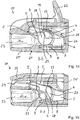
- Figure 7 shows a second embodiment of a spring-loaded terminal connection 1 in the perspective view.
- the contact legs 6 have webs 13 formed by opposing indentations 12 in an area adjoining the spring arch 5.
- the embodiments differ, on the one hand, in the mounting of the busbar 9 on the contact legs 6 and, on the other hand, in the design of the clamping leg 3.
- actuating tabs 19 protrude from the edge regions of the clamping leg 3.
- the actuating tabs 19 are bent slightly upwards in the direction of the contact leg 6 and form an actuation support on which an actuating element, such as a pivot lever, can apply an actuating force to open a clamping point by lifting the clamping leg 3 in the direction of the section of the contact leg 6 located above it.
- an actuating element such as a pivot lever
- two actuating tabs 19 for a clamping spring 2 are provided on the two opposite edge regions of the clamping leg 3.
- Figure 8 shows a side view of the spring-loaded terminal connection from FIG. It becomes clear once again that the busbar rests in the free end of the contact leg bent upwards in the direction of the busbar 9 through the U-shaped bend 17 and additionally with the bearing lugs 15 located behind it, which dip into the bearing openings 14 of the section of the contact leg 6 be fixed in position.
- Figure 9 omits a perspective view of the clamping spring 2 for the spring-loaded terminal connection Figures 7 and 8 detect. It becomes clear that now the individual clamping springs 2 arranged next to one another are separate from one another. In this embodiment, the bearing openings 14 are formed by indentations in the edge region of the contact leg 6 in the free end section and are therefore not completely closed on the circumference. It is also clear that the free end 18 of the free end section 8 is bent upwards from the plane of the free end section 8 in the direction of the web 13 or in the direction of the free clamping end 4 of the clamping leg located approximately above it. It can also be seen that the actuating tabs 19 are formed on both sides at the edge regions of the clamping leg 3 by cutting or punching free the clamping end 4 and folding it down in the direction of the free end section 8.
- Figure 10 omits a top view of the spring-loaded terminal connection 1 Figure 7 detect. It is clear here that the actuating tabs 19 are in the top view in the space below the webs 13 and the indentations 12 forming them. The free clamping end 4 of the clamping leg 3, the actuating tabs 19 and the indentations 12 for forming the webs 13 are thus approximately one above the other in alignment.
- Figure 11 omits a view of the spring-loaded terminal connection 1 Figure 7 Recognize the busbar 9 from below. It becomes clear here that the protruding bearing lugs 15 dip into the bearing openings 14 formed from indentations on the free end section 8 of the contact legs 6.
- Figure 12 shows a perspective view of a conductor connection terminal 20.
- the conductor connection terminal 20 has an insulating material housing 21 into which one of the spring-loaded terminal connections 1 described above is installed with three clamping springs 2 arranged next to one another (not visible).
- the spring-loaded terminal connections 1 ie to open the terminal points formed in this way for connecting an electrical one
- Actuating levers 22 are accommodated in the insulating material housing 21 so as to be able to pivot.
- the insulating material housing has conductor insertion openings 23 on the front side for inserting electrical conductors to an associated terminal point of a clamping spring 2. These conductor insertion openings 23 extend into conductor insertion opening L into the interior of the insulating material housing 21.
- test opening 24 extending in the conductor insertion direction L is present above the central conductor insertion opening 23.
- the test opening 24 is open at the front and towards the adjoining spring-force terminal connection 1 in the interior, so that with the aid of an inserted test tool it can be determined whether there is a voltage potential at the spring-force terminal connection 1.
- Figure 13 shows a top view of the conductor connection terminal 20 with the section lines AA and BB.
- the upper, in Figure 12 left, operating lever is in the open position and is pivoted away from the insulating housing.
- the clamping point of the associated clamping spring is thus opened.
- the other two actuating levers 22 are folded down in the closed position in the direction of the insulating material housing 21 so that the clamping point is closed and the associated clamping spring exerts a clamping force via the free clamping section 4 on the busbar underneath and any electrical conductor (not shown) lying therebetween.
- Figure 14 omits a side sectional view in section BB through the conductor connection terminal 21 Figures 12 and 13 detect. It is clear here that a spring-loaded terminal connection 1 described above is built into the interior of the insulating material housing 21.
- the insulating housing 21 is designed in two parts and has a clamping housing part 25 and a cover part 26 that closes this at the rear.
- the actuating lever 22, which is pivotably mounted in the insulating material housing 21 has a pivot bearing pin 27 with a V-shaped cutout 28 in the interior between the busbar 9 and the web 13 of about 80 to 120 ° (in the illustrated embodiment, about 110 °). With the V-shaped cutout 28, an actuating contour 29 is created which acts on an associated actuating tab 19 in order to displace the clamping leg 3 in the direction of the web 13 located above it in order to open the clamping point.
- Figure 15 shows a side sectional view of the conductor connection terminal 20 with the actuating lever 22 closed in section AA of Figure 13 detect. It becomes clear that the clamping point is now closed. This is achieved in that the pivot pin 27 is rotated by approximately 90 °. The actuating tab 19 is released and the clamping leg 3 can move freely under the spring force applied by the spring bow 5 and exert a clamping force on the busbar and an electrical conductor possibly arranged between the busbar and the free clamping end 4.
- a type of spring joint or hinge is formed by the web 13, so that a force acting via the clamping leg 3 and the spring bow is flexibly absorbed by the clamping spring 2 itself without transferring significant force to the insulating material housing.
- Figure 16 shows a second embodiment of a conductor connection terminal 20.
- the actuating levers 22 and the insulating housing 21 located between them are also designed to be slightly different.
- Figure 17 omits a top view of the second embodiment of the conductor connection terminal 20 Figure 16 recognize with the cutting lines AA and BB.
- Figure 18 shows the conductor connection terminal 20 Figures 16 and 17 in section BB of the open actuating lever 22 with the terminal point open.
- a part-circular pivot pin 27 is arranged at the level above the busbar 9 and below the web 13 and is pivotably mounted in the insulating material housing.
- the busbar 9 with a U-shaped bend 17 is comparable to the second exemplary embodiment of a spring-loaded terminal connection 1 according to FIG Figures 7 to 11 executed.
- the actuating contour 29 formed on the pivot pin 27 is somewhat different than in the first embodiment according to FIG Figures 14 and 15 executed, functionally but comparable. Essentially, reference can therefore be made to the description relating to the first exemplary embodiment.
- Figure 19 omits a side sectional view of the conductor connection terminal 20
- Figures 16 and 17 recognize in section AA with the actuating lever 22 closed.
- the terminal point is closed by the free terminal end 4 of the clamping leg 3 is pressed down in the direction of the busbar 9 by the spring force of the clamping spring 5. Without an inserted electrical conductor as shown, the free terminal end 4 then rests on the busbar.
Landscapes
- Connections Arranged To Contact A Plurality Of Conductors (AREA)
- Connections Effected By Soldering, Adhesion, Or Permanent Deformation (AREA)
- Clamps And Clips (AREA)
- Installation Of Bus-Bars (AREA)
- Multi-Conductor Connections (AREA)
- Connections By Means Of Piercing Elements, Nuts, Or Screws (AREA)
Priority Applications (1)
| Application Number | Priority Date | Filing Date | Title |
|---|---|---|---|
| EP25187130.7A EP4604321A3 (fr) | 2013-02-13 | 2014-02-12 | Borne à ressort et borne de connexion de conducteur |
Applications Claiming Priority (3)
| Application Number | Priority Date | Filing Date | Title |
|---|---|---|---|
| DE102013101411.9A DE102013101411B4 (de) | 2013-02-13 | 2013-02-13 | Federkraftklemmanschluss und Leiteranschlussklemme |
| EP14704144.6A EP2956994B1 (fr) | 2013-02-13 | 2014-02-12 | Borne de connexion à ressort et borne de connexion de connecteur |
| PCT/EP2014/052720 WO2014124962A1 (fr) | 2013-02-13 | 2014-02-12 | Borne de connexion à ressort et borne de connexion de connecteur |
Related Parent Applications (2)
| Application Number | Title | Priority Date | Filing Date |
|---|---|---|---|
| EP14704144.6A Division-Into EP2956994B1 (fr) | 2013-02-13 | 2014-02-12 | Borne de connexion à ressort et borne de connexion de connecteur |
| EP14704144.6A Division EP2956994B1 (fr) | 2013-02-13 | 2014-02-12 | Borne de connexion à ressort et borne de connexion de connecteur |
Related Child Applications (1)
| Application Number | Title | Priority Date | Filing Date |
|---|---|---|---|
| EP25187130.7A Division EP4604321A3 (fr) | 2013-02-13 | 2014-02-12 | Borne à ressort et borne de connexion de conducteur |
Publications (1)
| Publication Number | Publication Date |
|---|---|
| EP3836306A1 true EP3836306A1 (fr) | 2021-06-16 |
Family
ID=50097688
Family Applications (4)
| Application Number | Title | Priority Date | Filing Date |
|---|---|---|---|
| EP25187130.7A Pending EP4604321A3 (fr) | 2013-02-13 | 2014-02-12 | Borne à ressort et borne de connexion de conducteur |
| EP14704144.6A Active EP2956994B1 (fr) | 2013-02-13 | 2014-02-12 | Borne de connexion à ressort et borne de connexion de connecteur |
| EP18205463.5A Revoked EP3460919B1 (fr) | 2013-02-13 | 2014-02-12 | Pince de raccordement de conducteur |
| EP21155507.3A Pending EP3836306A1 (fr) | 2013-02-13 | 2014-02-12 | Pince de borne de conducteur |
Family Applications Before (3)
| Application Number | Title | Priority Date | Filing Date |
|---|---|---|---|
| EP25187130.7A Pending EP4604321A3 (fr) | 2013-02-13 | 2014-02-12 | Borne à ressort et borne de connexion de conducteur |
| EP14704144.6A Active EP2956994B1 (fr) | 2013-02-13 | 2014-02-12 | Borne de connexion à ressort et borne de connexion de connecteur |
| EP18205463.5A Revoked EP3460919B1 (fr) | 2013-02-13 | 2014-02-12 | Pince de raccordement de conducteur |
Country Status (9)
| Country | Link |
|---|---|
| US (1) | US9478874B2 (fr) |
| EP (4) | EP4604321A3 (fr) |
| JP (1) | JP6396334B2 (fr) |
| KR (1) | KR102149849B1 (fr) |
| CN (2) | CN109524802B (fr) |
| DE (2) | DE102013101411B4 (fr) |
| PL (1) | PL2956994T3 (fr) |
| RU (1) | RU2652780C2 (fr) |
| WO (1) | WO2014124962A1 (fr) |
Families Citing this family (45)
| Publication number | Priority date | Publication date | Assignee | Title |
|---|---|---|---|---|
| DE102013108116A1 (de) * | 2013-07-30 | 2015-02-19 | Phoenix Contact Gmbh & Co. Kg | Elektrische Anschlussklemme und Verfahren |
| DE102013110476A1 (de) * | 2013-09-23 | 2015-03-26 | Phoenix Contact Gmbh & Co. Kg | Kabelschuheinrichtung mit Strombalken sowie Anschlussklemme |
| EP3038213B1 (fr) * | 2014-12-22 | 2017-01-11 | Wago Verwaltungsgesellschaft mbH | Borne de connection de cable destinee a serrer au moins un conducteur electrique |
| DE102015100257A1 (de) * | 2014-12-22 | 2016-06-23 | Wago Verwaltungsgesellschaft Mbh | Leiteranschlussklemme zum Anklemmen wenigstens eines elektrischen Leiters |
| DE102015100823B4 (de) * | 2015-01-21 | 2021-12-09 | Phoenix Contact Gmbh & Co. Kg | Elektrische Anschlussklemme |
| CN204558667U (zh) * | 2015-04-11 | 2015-08-12 | 江门市创艺电器有限公司 | 一种接线端子连接器 |
| EP3139444A1 (fr) * | 2015-09-06 | 2017-03-08 | Utility Electrical Co., Ltd | Borne de conducteur avec poignée de commande |
| DE102015115612A1 (de) * | 2015-09-16 | 2017-03-16 | Phoenix Contact Gmbh & Co. Kg | Anschlussklemme zum Anschließen eines elektrischen Leiters |
| DE202015105023U1 (de) * | 2015-09-22 | 2016-12-23 | Weidmüller Interface GmbH & Co. KG | Anschlussvorrichtung für Leiter |
| DE102015119247B4 (de) * | 2015-11-09 | 2026-03-19 | Wago Verwaltungsgesellschaft Mbh | Verbindungsklemme |
| DE102016103658B4 (de) * | 2016-03-01 | 2025-08-21 | Gottlob Thumm Maschinenbau Gmbh | Prüfstation mit einer Kontaktiereinrichtung |
| DE102016111627A1 (de) | 2016-06-24 | 2017-12-28 | Wago Verwaltungsgesellschaft Mbh | Leiteranschlussklemme |
| DE102016111626B4 (de) * | 2016-06-24 | 2018-01-18 | Wago Verwaltungsgesellschaft Mbh | Leiteranschlussklemme |
| LU93148B1 (de) * | 2016-07-13 | 2018-01-23 | Phoenix Contact Gmbh & Co Kg Intellectual Property Licenses & Standards | Anschlussklemme |
| DE102016116966B4 (de) | 2016-09-09 | 2024-11-14 | Wago Verwaltungsgesellschaft Mbh | Federkraftklemmanschluss sowie Leiteranschlussklemme |
| US10461444B2 (en) | 2017-01-06 | 2019-10-29 | Hubbell Incorporated | Electrical wiring devices with screwless connection terminals |
| DE102017109701A1 (de) * | 2017-05-05 | 2018-11-08 | Wago Verwaltungsgesellschaft Mbh | Leiteranschlussklemme |
| DE202017107800U1 (de) * | 2017-05-12 | 2018-08-17 | Electro Terminal Gmbh & Co Kg | Klemme |
| CN108075254B (zh) * | 2017-07-12 | 2024-03-19 | 盐城世明电子器件有限公司 | 电连接器 |
| DE202017105467U1 (de) † | 2017-09-08 | 2018-12-12 | Wago Verwaltungsgesellschaft Mbh | Leiteranschlussklemme |
| EP3460917A1 (fr) | 2017-09-20 | 2019-03-27 | Delphi Technologies, Inc. | Connecteur électrique |
| EP3460918A1 (fr) * | 2017-09-20 | 2019-03-27 | Delphi Technologies, Inc. | Connecteur électrique |
| CN110011086B (zh) * | 2018-01-05 | 2024-08-20 | 泰科电子(上海)有限公司 | 导电端子及连接器 |
| DE102018107174B3 (de) | 2018-03-26 | 2019-09-19 | Gottlob Thumm Maschinenbau Gmbh | Kontaktiervorrichtung |
| WO2020046850A1 (fr) * | 2018-08-27 | 2020-03-05 | Molex, Llc | Ensemble de barres omnibus articulées |
| DE102018010359B4 (de) | 2018-10-05 | 2026-03-19 | Wago Verwaltungsgesellschaft Mbh | Kontakteinsatz einer Leiteranschlussklemme sowie damit gebildete Leiteranschlussklemme |
| DE102018124623B4 (de) | 2018-10-05 | 2022-07-07 | Wago Verwaltungsgesellschaft Mbh | Kontakteinsatz einer Leiteranschlussklemme sowie damit gebildete Leiteranschlussklemme |
| USD924144S1 (en) * | 2018-12-11 | 2021-07-06 | Pinyou ZHU | Connection terminal |
| DE202019101483U1 (de) * | 2019-03-15 | 2020-06-18 | WAGO Verwaltungsgesellschaft mit beschränkter Haftung | Federkraftklemmanschluss |
| US11495895B2 (en) | 2019-05-01 | 2022-11-08 | Hubbell Incorporated | Terminations for electrical wiring devices |
| DE102019116930B4 (de) * | 2019-06-24 | 2023-11-16 | WAGO Verwaltungsgesellschaft mit beschränkter Haftung | Elektrische Anschlussklemme |
| DE102019117302A1 (de) * | 2019-06-27 | 2020-12-31 | Phoenix Contact Gmbh & Co. Kg | Anschlussklemmenanordnung zum Anschließen mindestens eines elektrischen Leiters |
| DE102019117301A1 (de) * | 2019-06-27 | 2020-12-31 | Phoenix Contact Gmbh & Co. Kg | Anschlussklemme |
| DE102020100333B3 (de) * | 2020-01-09 | 2021-04-01 | Wago Verwaltungsgesellschaft Mbh | Klemmfeder und Leiteranschlussklemme |
| AU2021292753B2 (en) * | 2020-06-18 | 2023-12-21 | Ideal Industries, Inc. | Conductor terminal |
| RU200552U1 (ru) * | 2020-07-29 | 2020-10-29 | Дмитрий Вячеславович Назаров | Клемма соединительная для проводников |
| DE102021112961A1 (de) * | 2021-05-19 | 2022-11-24 | WAGO Verwaltungsgesellschaft mit beschränkter Haftung | Leiteranschlussklemme mit wenigstens einem Federkraftklemmanschluss |
| DE102021112960A1 (de) * | 2021-05-19 | 2022-11-24 | WAGO Verwaltungsgesellschaft mit beschränkter Haftung | Leiteranschlussklemme mit wenigstens einem Federkraftklemmanschluss |
| CN113451794B (zh) * | 2021-06-04 | 2023-03-21 | 厦门广泓工贸有限公司 | 一种接线夹 |
| CN113555839A (zh) * | 2021-08-31 | 2021-10-26 | 东莞市高格电子有限公司 | 一种用于电缆连接的新型连接器 |
| US12394920B2 (en) | 2021-09-27 | 2025-08-19 | Hubbell Incorporated | Screwless connection terminals with wire manager |
| WO2023177811A1 (fr) | 2022-03-16 | 2023-09-21 | Hubbell Incorporated | Dispositifs de câblage électrique à bornes de fil sans vis |
| CN114665287B (zh) * | 2022-04-15 | 2024-03-15 | 浙江瑞辉电气有限公司 | 导线连接装置 |
| US20240162632A1 (en) | 2022-11-16 | 2024-05-16 | Hubbell Incorporated | Multi-pole electrical wiring devices with wire termination assemblies |
| DE102023121565A1 (de) | 2023-08-11 | 2025-02-13 | WAGO Verwaltungsgesellschaft mit beschränkter Haftung | Leiteranschlussklemme |
Citations (9)
| Publication number | Priority date | Publication date | Assignee | Title |
|---|---|---|---|---|
| DE7537982U1 (fr) | 1975-11-28 | 1978-09-14 | Fischer, Karl, 7519 Oberderdingen | |
| JPS54121285U (fr) * | 1978-02-08 | 1979-08-24 | ||
| EP1081790A2 (fr) * | 1999-09-03 | 2001-03-07 | Weidmüller Interface GmbH & Co. | Pince à ressort pour raccorder un conducteur électrique |
| DE102004045026B3 (de) | 2004-09-15 | 2006-02-16 | Phoenix Contact Gmbh & Co. Kg | Elektrische Anschluß- oder Verbindungsklemme |
| DE102005048972A1 (de) | 2005-10-13 | 2007-04-19 | Phoenix Contact Gmbh & Co. Kg | Federkraftklemme mit Klemmfeder und Strombalken |
| EP1950837A1 (fr) * | 2007-01-03 | 2008-07-30 | Schneider Electric Espana, S.A. | Borne de connexion automatique |
| DE202009010003U1 (de) * | 2008-08-20 | 2009-12-03 | LEGRAND FRANCE (société anonyme) | Automatischer elektrischer Verbindungsanschluss |
| WO2012000639A1 (fr) | 2010-07-02 | 2012-01-05 | Phoenix Contact Gmbh & Co. Kg | Borne de connexion |
| US8262422B1 (en) * | 2011-07-28 | 2012-09-11 | Cheng Uei Precision Industry Co., Ltd. | Electrical connector |
Family Cites Families (31)
| Publication number | Priority date | Publication date | Assignee | Title |
|---|---|---|---|---|
| DE7420412U (de) * | 1974-06-14 | 1974-11-28 | Wago Kontakttechnik Gmbh | Schraubenlose Anschluß- oder Verbindungsklemme für elektrische Leitungen |
| JPS6015253Y2 (ja) * | 1980-11-07 | 1985-05-14 | 共和電器株式会社 | 電気機器類のア−ス用端子板 |
| DE59206463D1 (de) * | 1991-06-27 | 1996-07-11 | Sotax Ag | Kontaktorgan und Verfahren zur Herstellung des Kontaktorgans |
| US5651695A (en) * | 1993-07-16 | 1997-07-29 | Berg Technology, Inc. | Connector for electric wires |
| FR2732518B1 (fr) * | 1995-03-29 | 1997-04-30 | Entrelec Sa | Agencement de connexion pour fils conducteurs electriques et module, notamment de type bloc de jonction, equipe d'un tel agencement |
| DE19641206C2 (de) * | 1996-09-25 | 1999-12-23 | Wago Verwaltungs Gmbh | Anschlußklemme für elektrische Leiter |
| DE19654523C2 (de) * | 1996-12-19 | 2003-10-09 | Wago Verwaltungs Gmbh | Verbindungsklemme mit mindestens zwei Klemmstellen zum Anschließen elektrischer Leiter |
| DE19710306C2 (de) | 1997-02-26 | 2001-12-06 | Wago Verwaltungs Gmbh | Elektrische Klemme |
| DE19715971C1 (de) * | 1997-04-17 | 1998-05-07 | Phoenix Contact Gmbh & Co | Zugfederklemme mit aus einem Federblatt gebogener Klemmfeder |
| DE29914482U1 (de) * | 1999-08-23 | 2001-01-11 | Weidmüller Interface GmbH & Co, 32760 Detmold | Geräteanschlußklemme |
| JP3975897B2 (ja) * | 2002-11-26 | 2007-09-12 | 松下電工株式会社 | 速結端子装置並びに配線器具 |
| DE10304493A1 (de) * | 2003-02-05 | 2004-08-26 | Phoenix Contact Gmbh & Co. Kg | Zugfeder für eine elektrische Klemme |
| DE20303537U1 (de) * | 2003-03-05 | 2003-05-15 | Electro-Terminal Ges. M.B.H. & Co. Kg, Innsbruck | Schraubenlose Dosenklemme |
| DE20312861U1 (de) * | 2003-08-20 | 2003-10-30 | Phoenix Contact GmbH & Co. KG, 32825 Blomberg | Federkraftklemme |
| DE102004045025B3 (de) * | 2004-09-15 | 2006-02-16 | Phoenix Contact Gmbh & Co. Kg | Elektrische Anschluß- oder Verbindungsklemme |
| DE102006019150B4 (de) * | 2006-04-21 | 2011-06-09 | Wago Verwaltungsgesellschaft Mbh | Elektrische Verbindungsklemme |
| US7507106B2 (en) * | 2007-06-14 | 2009-03-24 | Ideal Industries, Inc. | Push-in wire connector with improved busbar |
| JP4803136B2 (ja) * | 2007-08-16 | 2011-10-26 | パナソニック電工株式会社 | 配線器具 |
| CN201130749Y (zh) * | 2007-08-17 | 2008-10-08 | 富士康(昆山)电脑接插件有限公司 | 电池连接器 |
| DE102008039868A1 (de) * | 2008-08-27 | 2010-03-04 | Phoenix Contact Gmbh & Co. Kg | Elektrische Anschlußklemme |
| DE102008060283B4 (de) | 2008-12-03 | 2011-08-25 | Tyco Electronics AMP GmbH, 64625 | Werkzeuglos betätigbare Anschlussklemmvorrichtung mit mehreren Klemmarmen für mehrere elektrische Leiter |
| DE202009002324U1 (de) | 2009-02-18 | 2010-07-29 | Weidmüller Interface GmbH & Co. KG | Anschlussklemme zum Anschluss von Leiterenden |
| JP4576469B1 (ja) * | 2009-05-14 | 2010-11-10 | タイコエレクトロニクスジャパン合同会社 | コンタクトおよび電気コネクタ |
| JP5540718B2 (ja) * | 2010-01-15 | 2014-07-02 | オムロン株式会社 | 電気コネクタ、電子機器および導電接触方法 |
| EP2363919B1 (fr) * | 2010-02-22 | 2012-07-04 | Tyco Electronics Nederland B.V. | Élément de contact pour connecteurs électriques |
| DE102010014143B4 (de) * | 2010-04-07 | 2016-07-07 | Wago Verwaltungsgesellschaft Mbh | Betätigungseinrichtung für eine elektrische Anschlussklemme |
| DE102010024809B4 (de) * | 2010-06-23 | 2013-07-18 | Wago Verwaltungsgesellschaft Mbh | Anschlussklemme |
| JP5958680B2 (ja) * | 2010-09-14 | 2016-08-02 | パナソニックIpマネジメント株式会社 | 端子装置 |
| DE102011051536A1 (de) * | 2011-07-04 | 2013-01-10 | Phoenix Contact Gmbh & Co. Kg | Klemmeinheit einer elektrischen Anschlussklemme |
| DE102011108828B4 (de) * | 2011-07-29 | 2013-06-27 | Phoenix Contact Gmbh & Co. Kg | Elektrische Anschlussvorrichtung |
| DE102011056410B4 (de) * | 2011-12-14 | 2013-06-27 | Wago Verwaltungsgesellschaft Mbh | Anschlussklemme |
-
2013
- 2013-02-13 DE DE102013101411.9A patent/DE102013101411B4/de not_active Withdrawn - After Issue
-
2014
- 2014-02-12 WO PCT/EP2014/052720 patent/WO2014124962A1/fr not_active Ceased
- 2014-02-12 JP JP2015557410A patent/JP6396334B2/ja active Active
- 2014-02-12 KR KR1020157021571A patent/KR102149849B1/ko active Active
- 2014-02-12 EP EP25187130.7A patent/EP4604321A3/fr active Pending
- 2014-02-12 PL PL14704144T patent/PL2956994T3/pl unknown
- 2014-02-12 EP EP14704144.6A patent/EP2956994B1/fr active Active
- 2014-02-12 CN CN201811425168.1A patent/CN109524802B/zh active Active
- 2014-02-12 US US14/767,714 patent/US9478874B2/en active Active
- 2014-02-12 RU RU2015138698A patent/RU2652780C2/ru active
- 2014-02-12 DE DE202014011262.2U patent/DE202014011262U1/de not_active Expired - Lifetime
- 2014-02-12 CN CN201480008755.4A patent/CN104995800B/zh active Active
- 2014-02-12 EP EP18205463.5A patent/EP3460919B1/fr not_active Revoked
- 2014-02-12 EP EP21155507.3A patent/EP3836306A1/fr active Pending
Patent Citations (9)
| Publication number | Priority date | Publication date | Assignee | Title |
|---|---|---|---|---|
| DE7537982U1 (fr) | 1975-11-28 | 1978-09-14 | Fischer, Karl, 7519 Oberderdingen | |
| JPS54121285U (fr) * | 1978-02-08 | 1979-08-24 | ||
| EP1081790A2 (fr) * | 1999-09-03 | 2001-03-07 | Weidmüller Interface GmbH & Co. | Pince à ressort pour raccorder un conducteur électrique |
| DE102004045026B3 (de) | 2004-09-15 | 2006-02-16 | Phoenix Contact Gmbh & Co. Kg | Elektrische Anschluß- oder Verbindungsklemme |
| DE102005048972A1 (de) | 2005-10-13 | 2007-04-19 | Phoenix Contact Gmbh & Co. Kg | Federkraftklemme mit Klemmfeder und Strombalken |
| EP1950837A1 (fr) * | 2007-01-03 | 2008-07-30 | Schneider Electric Espana, S.A. | Borne de connexion automatique |
| DE202009010003U1 (de) * | 2008-08-20 | 2009-12-03 | LEGRAND FRANCE (société anonyme) | Automatischer elektrischer Verbindungsanschluss |
| WO2012000639A1 (fr) | 2010-07-02 | 2012-01-05 | Phoenix Contact Gmbh & Co. Kg | Borne de connexion |
| US8262422B1 (en) * | 2011-07-28 | 2012-09-11 | Cheng Uei Precision Industry Co., Ltd. | Electrical connector |
Also Published As
| Publication number | Publication date |
|---|---|
| WO2014124962A1 (fr) | 2014-08-21 |
| PL2956994T3 (pl) | 2021-10-25 |
| CN109524802A (zh) | 2019-03-26 |
| KR20150119856A (ko) | 2015-10-26 |
| EP3460919B1 (fr) | 2019-11-27 |
| US20150372401A1 (en) | 2015-12-24 |
| EP3460919A1 (fr) | 2019-03-27 |
| US9478874B2 (en) | 2016-10-25 |
| EP4604321A2 (fr) | 2025-08-20 |
| CN104995800A (zh) | 2015-10-21 |
| EP2956994A1 (fr) | 2015-12-23 |
| DE102013101411A1 (de) | 2014-08-14 |
| CN109524802B (zh) | 2021-02-19 |
| DE202014011262U1 (de) | 2018-11-21 |
| EP2956994B1 (fr) | 2021-04-07 |
| CN104995800B (zh) | 2018-12-25 |
| RU2652780C2 (ru) | 2018-05-08 |
| RU2015138698A (ru) | 2017-03-20 |
| EP4604321A3 (fr) | 2025-10-29 |
| JP2016507148A (ja) | 2016-03-07 |
| KR102149849B1 (ko) | 2020-09-01 |
| DE102013101411B4 (de) | 2018-03-22 |
| JP6396334B2 (ja) | 2018-09-26 |
Similar Documents
| Publication | Publication Date | Title |
|---|---|---|
| EP2956994B1 (fr) | Borne de connexion à ressort et borne de connexion de connecteur | |
| EP3298659B1 (fr) | Borne de connexion de conducteur | |
| EP3476007B1 (fr) | Borne de connexion de conducteur | |
| EP2956992B1 (fr) | Borne de connexion de conducteur | |
| EP2917971B1 (fr) | Connexion par borne à ressort et appareil électrique contenant ladite connexion | |
| EP3627625B1 (fr) | Borne de raccordement | |
| EP2956993B1 (fr) | Contact à serrage par ressort et borne de connexion de conducteurs électriques | |
| EP3350883B1 (fr) | Élément de contact de borne de conducteur | |
| EP3042419B1 (fr) | Borne de raccordement à ressort | |
| DE102013104394B4 (de) | Leiteranschlussklemme | |
| EP3454422B1 (fr) | Borne de connexion conductrice | |
| EP3595090B1 (fr) | Borne de connexion conductrice | |
| DE102012110895A1 (de) | Anschlussklemme | |
| EP3145031B1 (fr) | Borne de connexion conductrice | |
| DE202017101148U1 (de) | Leiteranschlusskontaktelement | |
| EP2614556B1 (fr) | Dispositif de raccordement | |
| EP3776743B1 (fr) | Borne de connexion de conducteur, ressort de serrage d'une borne de connexion de conducteur et bloc de jonction | |
| DE102014119406B4 (de) | Anschlussklemme | |
| EP1920502B1 (fr) | Dispositif de serrage permettant de connecter un conducteur sans denudage | |
| DE29622991U1 (de) | Kontaktorgan mit Doppel-Schneidklemmanschluß |
Legal Events
| Date | Code | Title | Description |
|---|---|---|---|
| PUAI | Public reference made under article 153(3) epc to a published international application that has entered the european phase |
Free format text: ORIGINAL CODE: 0009012 |
|
| STAA | Information on the status of an ep patent application or granted ep patent |
Free format text: STATUS: REQUEST FOR EXAMINATION WAS MADE |
|
| 17P | Request for examination filed |
Effective date: 20210205 |
|
| AC | Divisional application: reference to earlier application |
Ref document number: 2956994 Country of ref document: EP Kind code of ref document: P |
|
| AK | Designated contracting states |
Kind code of ref document: A1 Designated state(s): AL AT BE BG CH CY CZ DE DK EE ES FI FR GB GR HR HU IE IS IT LI LT LU LV MC MK MT NL NO PL PT RO RS SE SI SK SM TR |
|
| TPAC | Observations filed by third parties |
Free format text: ORIGINAL CODE: EPIDOSNTIPA |
|
| STAA | Information on the status of an ep patent application or granted ep patent |
Free format text: STATUS: EXAMINATION IS IN PROGRESS |
|
| 17Q | First examination report despatched |
Effective date: 20220916 |