EP3836369A1 - Machine électrique rotative et prise de conversion de mode de ventilation pour une machine électrique rotative - Google Patents
Machine électrique rotative et prise de conversion de mode de ventilation pour une machine électrique rotative Download PDFInfo
- Publication number
- EP3836369A1 EP3836369A1 EP19214588.6A EP19214588A EP3836369A1 EP 3836369 A1 EP3836369 A1 EP 3836369A1 EP 19214588 A EP19214588 A EP 19214588A EP 3836369 A1 EP3836369 A1 EP 3836369A1
- Authority
- EP
- European Patent Office
- Prior art keywords
- shaft
- housing
- opening
- electric machine
- rotating electric
- Prior art date
- Legal status (The legal status is an assumption and is not a legal conclusion. Google has not performed a legal analysis and makes no representation as to the accuracy of the status listed.)
- Withdrawn
Links
Images


Classifications
-
- H—ELECTRICITY
- H02—GENERATION; CONVERSION OR DISTRIBUTION OF ELECTRIC POWER
- H02K—DYNAMO-ELECTRIC MACHINES
- H02K9/00—Arrangements for cooling or ventilating
- H02K9/02—Arrangements for cooling or ventilating by ambient air flowing through the machine
- H02K9/04—Arrangements for cooling or ventilating by ambient air flowing through the machine having means for generating a flow of cooling medium
- H02K9/06—Arrangements for cooling or ventilating by ambient air flowing through the machine having means for generating a flow of cooling medium with fans or impellers driven by the machine shaft
-
- H—ELECTRICITY
- H02—GENERATION; CONVERSION OR DISTRIBUTION OF ELECTRIC POWER
- H02K—DYNAMO-ELECTRIC MACHINES
- H02K5/00—Casings; Enclosures; Supports
- H02K5/04—Casings or enclosures characterised by the shape, form or construction thereof
- H02K5/10—Casings or enclosures characterised by the shape, form or construction thereof with arrangements for protection from ingress, e.g. water or fingers
-
- H—ELECTRICITY
- H02—GENERATION; CONVERSION OR DISTRIBUTION OF ELECTRIC POWER
- H02K—DYNAMO-ELECTRIC MACHINES
- H02K7/00—Arrangements for handling mechanical energy structurally associated with dynamo-electric machines, e.g. structural association with mechanical driving motors or auxiliary dynamo-electric machines
- H02K7/003—Couplings; Details of shafts
-
- H—ELECTRICITY
- H02—GENERATION; CONVERSION OR DISTRIBUTION OF ELECTRIC POWER
- H02K—DYNAMO-ELECTRIC MACHINES
- H02K5/00—Casings; Enclosures; Supports
- H02K5/04—Casings or enclosures characterised by the shape, form or construction thereof
- H02K5/18—Casings or enclosures characterised by the shape, form or construction thereof with ribs or fins for improving heat transfer
Definitions
- the present invention relates to a rotating electric machine, and more specifically, to a rotating electrical machine with a conversion plug for convention the ventilation mode of the machine.
- the housing is adapted to house a number of internal components and also to receive a number of external accessories and components which are secured to the housing by different fastening systems.
- the rotating electric machines can also include ventilation systems, whose purpose is to dissipate the heat generated by the machine, keeping its internal temperature within pre-established operating limits.
- Ventiler modes In the mechanical design of rotating electric machines, different ventilation modes can be selected. Two commonly used ventilation modes are the TEFC ( totally enclosed fan cooled ) mode and the TEAO ( totally enclosed air over ) mode.
- TEFC totally enclosed fan cooled
- TEAO totally enclosed air over
- Machines using the TEFC ventilation mode comprise a fan mounted on the machine shaft, outside the housing, and a deflector cover over the fan. Thus, heat dissipation is done through the outer surface of the enclosure.
- Machines using the TEAO ventilation mode are generally exempt from their own ventilation system, and their cooling comes from the very application in which the machine is coupled, and which generates the airflow that passes over the enclosure.
- the adopted ventilation mode influences the mechanical design of the electric machine, so that different housings and shafts are used for different ventilation modes.
- the present invention contemplates a rotating electric machine of the type comprising a housing that houses an active core with a rotor and a stator, the rotor being mounted on a shaft, the housing having an opening aligned with the shaft, and the opening being configured to receive, without any change in shaft length, one of: a fan configured to be mounted to the shaft; and a conversion plug configured to close the opening.
- the conversion plug comprises a cylindrical body part sized to fit, by interference, to the opening of the housing; and a lid part having a diameter greater than the diameter of the opening of the housing.
- the fan comprises a hub portion configured for engagement with the end of shaft.
- the hub portion may comprise an inner circular shoulder cooperating with a circular recess at the end of the shaft, and the shaft may comprise a bevel cooperating with an end of the hub portion.
- FIGS 1 to 7 show an embodiment of the rotating electric machine according to the present invention.
- the electric motor comprises a housing 1 split in the axial direction, formed by a first housing part 1a and a second housing part 1b.
- the housing of the motor houses a number of internal components and receives a number of external accessories and components which are secured to the housing by different fastening systems.
- the electric motor of figure 1 has a terminal box 2, a foot 3, a flange 4, a shaft 8 and a deflector cover 5. The function of these components is well known to those skilled in the art and will not be here discussed in detail.
- Figure 2 shows the electric motor without the deflector cover 5, so that the fan 6 is visible.
- the housing has an opening axially coincident with the shaft 8 of the electric motor so as to allow the fan 6 to be mounted to the shaft.
- the electric machine of the present invention is operated in a TEFC ventilation mode, wherein the fan 6 is mounted / fixed to the electric machine shaft.
- Figure 3 is a cross-sectional view showing the attachment of fan 6 to the shaft 8, and figure 4 shows an enlarged view of the end of the shaft 8 that receives the fan.
- the fan 6 has a hub portion 6a configured to engage with the end of the shaft 8.
- the hub portion 6a comprises an inner circular shoulder 6b which cooperates with a circular recess 8b at the end of the shaft.
- the end of the shaft has a diameter difference between the shaft portions 8a and 8d, forming a bevel 8c surrounding the shaft.
- the end 6c of the hub portion 6a rests against the bevel 8c of the shaft 8.
- the rear end 9 of the electrical machine housing may further comprise a labyrinth portion 10 near the hole through which the shaft passes.
- the hub portion 6a further comprises a circular labyrinth wall 6d that cooperates with the labyrinth portion 10 of the rear end 9 of the housing.
- the shaft end 8 is sized such that the shaft portion 8a is configured to contact a bearing 11, with the end 6c of the hub portion 6a resting on the bevel 8c.
- the present invention provides an effective means for converting the ventilation of the electrical machine of the present invention from a TEFC type ventilation mode to a TEAO type ventilation mode, and vice versa.
- the electric machine of the present invention comprises a conversion plug 7 which is configured to close the fan attachment opening, after the removal of the fan.
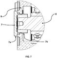
- Figure 5 shows the rotating electric machine of the present invention with the conversion plug 7 inserted
- Figure 6 shows a perspective view of the conversion plug 7.
- the plug 7 may be made, for example, of polymer, elastomer or metal.
- the deflector cover 5 and fun 6 are removed and, as best illustrated in Figure 5 , the conversion plug 7 is inserted into the opening of the housing. It is noteworthy that the conversion is performed without requiring any change in the length of the shaft.
- the shaft length is such that the shaft end receiving the fan does not project axially out of the housing opening.
- the conversion plug 7 comprises a cylindrical body part 7a and a lid part 7b.
- the cylindrical body part 7a is sized to fit, by interference, to opening of housing, and the lid part 7b has a diameter larger than the diameter of the opening of the housing, so as to seal the opening and serve as a stop for the plug .
- the present invention enables the conversion of ventilation modes with the same mechanical design of the housing and shaft, with a simple and inexpensive solution.
Landscapes
- Engineering & Computer Science (AREA)
- Power Engineering (AREA)
- Motor Or Generator Frames (AREA)
Priority Applications (1)
| Application Number | Priority Date | Filing Date | Title |
|---|---|---|---|
| EP19214588.6A EP3836369A1 (fr) | 2019-12-09 | 2019-12-09 | Machine électrique rotative et prise de conversion de mode de ventilation pour une machine électrique rotative |
Applications Claiming Priority (1)
| Application Number | Priority Date | Filing Date | Title |
|---|---|---|---|
| EP19214588.6A EP3836369A1 (fr) | 2019-12-09 | 2019-12-09 | Machine électrique rotative et prise de conversion de mode de ventilation pour une machine électrique rotative |
Publications (1)
| Publication Number | Publication Date |
|---|---|
| EP3836369A1 true EP3836369A1 (fr) | 2021-06-16 |
Family
ID=68840996
Family Applications (1)
| Application Number | Title | Priority Date | Filing Date |
|---|---|---|---|
| EP19214588.6A Withdrawn EP3836369A1 (fr) | 2019-12-09 | 2019-12-09 | Machine électrique rotative et prise de conversion de mode de ventilation pour une machine électrique rotative |
Country Status (1)
| Country | Link |
|---|---|
| EP (1) | EP3836369A1 (fr) |
Citations (3)
| Publication number | Priority date | Publication date | Assignee | Title |
|---|---|---|---|---|
| DE19508004A1 (de) * | 1995-03-07 | 1996-09-12 | Siemens Ag | Anordnung eines Lüfters an einer elektrischen Maschine |
| DE102009056007A1 (de) * | 2009-11-26 | 2011-06-01 | Hella Kgaa Hueck & Co. | Anordnung eines Verschlussstopfens in einer Montagebohrung eines Motorengehäuses und Verfahren zur Anbringung eines Verschlussstopfens in einer Montagebohrung eines Motorengehäuses |
| CN106374668A (zh) * | 2016-09-22 | 2017-02-01 | 无锡江南奕帆电力传动科技股份有限公司 | 一种电机防水结构 |
-
2019
- 2019-12-09 EP EP19214588.6A patent/EP3836369A1/fr not_active Withdrawn
Patent Citations (3)
| Publication number | Priority date | Publication date | Assignee | Title |
|---|---|---|---|---|
| DE19508004A1 (de) * | 1995-03-07 | 1996-09-12 | Siemens Ag | Anordnung eines Lüfters an einer elektrischen Maschine |
| DE102009056007A1 (de) * | 2009-11-26 | 2011-06-01 | Hella Kgaa Hueck & Co. | Anordnung eines Verschlussstopfens in einer Montagebohrung eines Motorengehäuses und Verfahren zur Anbringung eines Verschlussstopfens in einer Montagebohrung eines Motorengehäuses |
| CN106374668A (zh) * | 2016-09-22 | 2017-02-01 | 无锡江南奕帆电力传动科技股份有限公司 | 一种电机防水结构 |
Similar Documents
| Publication | Publication Date | Title |
|---|---|---|
| US6278207B1 (en) | Blower | |
| US6987336B2 (en) | Electric motor with screwless plug-type mounting | |
| JP7039168B2 (ja) | 電気モータ | |
| JP4479799B2 (ja) | 車両用交流発電機 | |
| CN110495078A (zh) | 马达 | |
| US20200198667A1 (en) | Covering system for wheelset shafts of rail vehicles | |
| KR20030045159A (ko) | 소형 모터 | |
| JP2016167942A (ja) | ブラシレスモータ | |
| US20040232787A1 (en) | Electric motor | |
| JP3051656B2 (ja) | 自動車用モータの冷却構造 | |
| US10224791B2 (en) | Electric motor and machine tool equipped with the electric motor | |
| JP2010041854A (ja) | 電動モータ | |
| EP3456978B1 (fr) | Dispositif de soufflage | |
| EP3836369A1 (fr) | Machine électrique rotative et prise de conversion de mode de ventilation pour une machine électrique rotative | |
| JP5009219B2 (ja) | 電動モータ | |
| CN115378183A (zh) | 具有定子壳体和轴承法兰的电机 | |
| US10746180B2 (en) | Blower device | |
| JP2016167943A (ja) | ブラシレスモータ | |
| CN113037014A (zh) | 旋转电机和旋转电机的通风模式转换插头 | |
| JP2010028901A (ja) | 電動モータ | |
| BR102019026076A2 (pt) | Máquina elétrica girante e tampão de conversão de modo de ventilação para uma máquina elétrica girante | |
| CN114830507A (zh) | 用于手持式工具机的电动马达 | |
| JP5102109B2 (ja) | 電動モータ | |
| CN214900435U (zh) | 电机 | |
| BR102019026076B1 (pt) | Máquina elétrica girante e tampão de conversão de modo de ventilação para uma máquina elétrica girante |
Legal Events
| Date | Code | Title | Description |
|---|---|---|---|
| PUAI | Public reference made under article 153(3) epc to a published international application that has entered the european phase |
Free format text: ORIGINAL CODE: 0009012 |
|
| STAA | Information on the status of an ep patent application or granted ep patent |
Free format text: STATUS: THE APPLICATION HAS BEEN PUBLISHED |
|
| AK | Designated contracting states |
Kind code of ref document: A1 Designated state(s): AL AT BE BG CH CY CZ DE DK EE ES FI FR GB GR HR HU IE IS IT LI LT LU LV MC MK MT NL NO PL PT RO RS SE SI SK SM TR |
|
| STAA | Information on the status of an ep patent application or granted ep patent |
Free format text: STATUS: REQUEST FOR EXAMINATION WAS MADE |
|
| 17P | Request for examination filed |
Effective date: 20211214 |
|
| RBV | Designated contracting states (corrected) |
Designated state(s): AL AT BE BG CH CY CZ DE DK EE ES FI FR GB GR HR HU IE IS IT LI LT LU LV MC MK MT NL NO PL PT RO RS SE SI SK SM TR |
|
| STAA | Information on the status of an ep patent application or granted ep patent |
Free format text: STATUS: EXAMINATION IS IN PROGRESS |
|
| 17Q | First examination report despatched |
Effective date: 20250702 |
|
| STAA | Information on the status of an ep patent application or granted ep patent |
Free format text: STATUS: THE APPLICATION IS DEEMED TO BE WITHDRAWN |
|
| 18D | Application deemed to be withdrawn |
Effective date: 20251104 |