EP3840652B1 - Procédé et appareil de dépistage d'amyloïde - Google Patents
Procédé et appareil de dépistage d'amyloïde Download PDFInfo
- Publication number
- EP3840652B1 EP3840652B1 EP19755573.3A EP19755573A EP3840652B1 EP 3840652 B1 EP3840652 B1 EP 3840652B1 EP 19755573 A EP19755573 A EP 19755573A EP 3840652 B1 EP3840652 B1 EP 3840652B1
- Authority
- EP
- European Patent Office
- Prior art keywords
- radiation
- counts
- patient
- radiation detector
- metric
- Prior art date
- Legal status (The legal status is an assumption and is not a legal conclusion. Google has not performed a legal analysis and makes no representation as to the accuracy of the status listed.)
- Active
Links
Images

Classifications
-
- A—HUMAN NECESSITIES
- A61—MEDICAL OR VETERINARY SCIENCE; HYGIENE
- A61B—DIAGNOSIS; SURGERY; IDENTIFICATION
- A61B6/00—Apparatus or devices for radiation diagnosis; Apparatus or devices for radiation diagnosis combined with radiation therapy equipment
- A61B6/50—Apparatus or devices for radiation diagnosis; Apparatus or devices for radiation diagnosis combined with radiation therapy equipment specially adapted for specific body parts; specially adapted for specific clinical applications
- A61B6/501—Apparatus or devices for radiation diagnosis; Apparatus or devices for radiation diagnosis combined with radiation therapy equipment specially adapted for specific body parts; specially adapted for specific clinical applications for diagnosis of the head, e.g. neuroimaging or craniography
-
- A—HUMAN NECESSITIES
- A61—MEDICAL OR VETERINARY SCIENCE; HYGIENE
- A61B—DIAGNOSIS; SURGERY; IDENTIFICATION
- A61B6/00—Apparatus or devices for radiation diagnosis; Apparatus or devices for radiation diagnosis combined with radiation therapy equipment
- A61B6/04—Positioning of patients; Tiltable beds or the like
-
- A—HUMAN NECESSITIES
- A61—MEDICAL OR VETERINARY SCIENCE; HYGIENE
- A61B—DIAGNOSIS; SURGERY; IDENTIFICATION
- A61B6/00—Apparatus or devices for radiation diagnosis; Apparatus or devices for radiation diagnosis combined with radiation therapy equipment
- A61B6/40—Arrangements for generating radiation specially adapted for radiation diagnosis
- A61B6/4057—Arrangements for generating radiation specially adapted for radiation diagnosis by using radiation sources located in the interior of the body
-
- A—HUMAN NECESSITIES
- A61—MEDICAL OR VETERINARY SCIENCE; HYGIENE
- A61B—DIAGNOSIS; SURGERY; IDENTIFICATION
- A61B6/00—Apparatus or devices for radiation diagnosis; Apparatus or devices for radiation diagnosis combined with radiation therapy equipment
- A61B6/42—Arrangements for detecting radiation specially adapted for radiation diagnosis
- A61B6/4208—Arrangements for detecting radiation specially adapted for radiation diagnosis characterised by using a particular type of detector
- A61B6/4258—Arrangements for detecting radiation specially adapted for radiation diagnosis characterised by using a particular type of detector for detecting non x-ray radiation, e.g. gamma radiation
-
- A—HUMAN NECESSITIES
- A61—MEDICAL OR VETERINARY SCIENCE; HYGIENE
- A61B—DIAGNOSIS; SURGERY; IDENTIFICATION
- A61B6/00—Apparatus or devices for radiation diagnosis; Apparatus or devices for radiation diagnosis combined with radiation therapy equipment
- A61B6/52—Devices using data or image processing specially adapted for radiation diagnosis
- A61B6/5211—Devices using data or image processing specially adapted for radiation diagnosis involving processing of medical diagnostic data
- A61B6/5217—Devices using data or image processing specially adapted for radiation diagnosis involving processing of medical diagnostic data extracting a diagnostic or physiological parameter from medical diagnostic data
-
- G—PHYSICS
- G16—INFORMATION AND COMMUNICATION TECHNOLOGY [ICT] SPECIALLY ADAPTED FOR SPECIFIC APPLICATION FIELDS
- G16H—HEALTHCARE INFORMATICS, i.e. INFORMATION AND COMMUNICATION TECHNOLOGY [ICT] SPECIALLY ADAPTED FOR THE HANDLING OR PROCESSING OF MEDICAL OR HEALTHCARE DATA
- G16H50/00—ICT specially adapted for medical diagnosis, medical simulation or medical data mining; ICT specially adapted for detecting, monitoring or modelling epidemics or pandemics
- G16H50/30—ICT specially adapted for medical diagnosis, medical simulation or medical data mining; ICT specially adapted for detecting, monitoring or modelling epidemics or pandemics for calculating health indices; for individual health risk assessment
-
- A—HUMAN NECESSITIES
- A61—MEDICAL OR VETERINARY SCIENCE; HYGIENE
- A61B—DIAGNOSIS; SURGERY; IDENTIFICATION
- A61B6/00—Apparatus or devices for radiation diagnosis; Apparatus or devices for radiation diagnosis combined with radiation therapy equipment
- A61B6/02—Arrangements for diagnosis sequentially in different planes; Stereoscopic radiation diagnosis
- A61B6/03—Computed tomography [CT]
- A61B6/037—Emission tomography
Definitions
- the following relates generally to the image acquisition arts, brain image arts, beta amyloid imaging arts, and related arts.
- CT computed tomography
- a device for performing an amyloid assessment includes a radiation detector assembly including at least one radiation detector. At least one electronic processor is programmed to: detect radiation counts over a data acquisition time interval using the radiation detector assembly; compute at least one current count metric from the detected radiation counts; store the at least one current count metric associated with a current test date in a non-transitory storage medium; and determine an amyloid metric based on a comparison of the at least one current count metric with a count metric stored in the non-transitory storage medium associated with an earlier test date.
- a radiation detector assembly include a back radiation detector and two side radiation detectors.
- the back radiation detector and the two side radiation detectors are arranged to define a cavity sized to receive a head with the back radiation detector arranged to view a backside of the head disposed in the cavity and the two side radiation detectors arranged to view left and right sides of the head disposed in the cavity.
- a method for performing a clinical assessment includes: obtaining imaging data using a radiation detector assembly including at least one radiation detector mounted in or on a patient support on which the patient is positioned to view a head of the positioned patient; detecting radiation counts from a radiotracer administered to the patient that binds with a targeted protein over a data acquisition time interval; computing at least one current count metric from the detected radiation counts; and determining a metric of deposits of the targeted protein in the head of the positioned patient based on a comparison of the at least one current count metric with a previous count metric.
- One advantage resides in providing a low cost device for assessing build-up of beta amyloid or another amyloid or other targeted protein in the brain.
- Another advantage resides in providing an imaging device in which a patient to be imaged takes a reduced radiopharmaceutical dose.
- Another advantage resides in providing a device for early detection of gradual build-up of amyloid deposits.
- a given embodiment may provide none, one, two, more, or all of the foregoing advantages, and/or may provide other advantages as will become apparent to one of ordinary skill in the art upon reading and understanding the present disclosure.
- Beta amyloid (A ⁇ ) deposits in brain tissue have been correlated with certain neurodegenerative diseases such as Alzheimer's disease.
- Other types of amyloid deposits have been correlated with other neurological diseases, such as alpha-synuclein which has been correlated with Parkinson's disease, and even more generally various types of protein deposits have been correlated with various neurological diseases, e.g. tau protein deposits have been correlated with Chronic Traumatic Encephalopathy (CTE).
- PET or single photon emission computed tomography (SPECT) imaging can be used in conjunction with a radiotracer that preferentially binds to A ⁇ in order to image beta amyloid deposits in the brain, thus providing a screening tool for detecting and monitoring these diseases.
- PET or SPECT is not an ideal choice for patient screening. The techniques are expensive to perform, and require delivery of a relatively high radioactive dose to the patient.
- the metric of deposits of the targeted protein in the head is based on a comparison of a current count metric with a previous count metric (e.g., obtained in an earlier test date). This automatically normalizes out individual factors and focuses the metric on change over time, which is more likely to be clinically significant as compared with a metric that is referenced to nominally similar measurements in a nominally similar patient cohort.
- a low cost radiation detector is integrated into the head region of a patient couch, along with a radiation shielding collar arranged to fit around the patient's neck to reduce detection of stray radiation from the torso region.
- the goal is to measure the total counts for a fixed acquisition time (or equivalently, the count rate) measured after delivery of a radiotracer targeting the amyloid or other targeted protein deposits.
- Further cost reduction is achieved in some embodiments by detecting singles rather than coincidences, and/or omitting or simplifying image generation, and/or omitting the conventional coincidence detection circuitry and/or radiation collimator (with consequent loss of imaging capability).
- Low dose is achieved in part by measuring counts for a large portion of the brain, or for the entire brain; rather than using a local radiation probe or effectively partitioning the detected counts into image voxel values by way of image reconstruction.
- multiple radiation detectors are arranged surrounding a portion or all of the head, thereby further maximizing detected counts and allowing for further reduction in radiotracer dosage.
- Various implementations can be implemented, such as a threeor four-detector slab design with a backside slab embedded in the table, two side slabs arranged left and right of the head, and an optional crown slab positioned "above" the crown of the head.
- the side and crown slabs can be mounted on rails and slid into contact with the sides and crown of the head, thereby also providing stabilization of the head and motion suppression.
- a radiation-shielding collar fitted around the patient's neck may provide further head stabilization and also operate to block stray counts from radiotracer concentrations in the torso or other body portions "below" the head.
- a further detector slab could be placed in front of the patient's face, but the potential for inducing claustrophobia may be a factor in deciding whether to include (or use) this additional detector slab.
- the term "patient” broadly denotes the person undergoing the clinical assessment of beta amyloid (or other targeted protein) deposits in the brain (i.e. head).
- the patient may be a patient diagnosed with early-onset Alzheimer's disease or another chronic neurological condition whose clinical progression is being monitored, or the patient may be a healthy individual who is merely undergoing screening for beta amyloid deposits.
- an advantage of the disclosed approaches is that their low cost and reduced radiotracer dosage makes these approaches well-suited for use in screening healthy patients, possibly on an out-patient basis or during a routine medical examination (e.g. during the patient's annual physical examination).
- Counts at a fixed time after administration of the radiopharmaceutical can be a suitable metric, but this relies upon precise timing of the measurement and might be susceptible to differences in radiotracer dosage and uptake between sessions due to metabolic differences or so forth.
- Another approach is to measure the counts-versus-time curve, from which various metrics such as peak counts, FWHM of the uptake curve, ramp-up slope, washout decay constant, area-under-curve, or so forth may be extracted.
- the desire for high temporal resolution in the counts-versus-time curve may be balanced against the need for sufficient counts statistics in each time bin.
- the metrics may be adjusted or normalized for injected quantity of the radiotracer, patient weight or body mass index (BMI), age (to account for natural buildup of A ⁇ due to aging), and/or other variables such as gender or ethnicity.
- no imaging is performed.
- This permits cost savings such as elimination of timestamping circuitry and coincidence detection and/or the use of radiation collimators (e.g. honeycomb collimators mounted on the front of the radiation detectors), use of a radiation detector with coarse resolution or even a single large area detector (also facilitated by use of low radiotracer dose and consequent reduction in potential for pileup of counts), elimination of scatter correction, and enabling use of a stationary detector that does not completely encircle the head of the patient.
- the energy window for singles detection can be enlarged toward the low-energy end to intentionally count in-elastically scattered events, again enabling further dose reduction.
- Scattered events are problematic for imaging since the sourcing radioactive decay event does not generally lie on the "line of response" defined by a coincidence or a radiation collimator, and scatter events are largely removed by employing an energy window that filters out scattered detections that have lost energy during the (inelastic) scattering.
- these scattered events can be retained by extending the energy window on the low energy side, thereby increasing the total counts.
- imaging is performed.
- radiation detectors providing multiple viewpoints are provided, such as the mentioned design with a backside detector, side detectors, and an optional crown detector.
- a low resolution image is sufficient to provide some visual context for the clinician, since the clinical results are derived from the total or average counts.
- coincidence detection is employed for spatial encoding of the counts.
- a radiation collimator e.g., a honeycomb collimator
- the collimator can be provided as a set of slats or a grid that is inserted into a receiving slot of the radiation detector or its mount when imaging is desired.
- the "imaging” is a one-dimensional (1D) counts profile line.
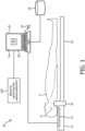
- an illustrative device or system 10 for performing beta amyloid assessment is shown.
- beta amyloid assessment is described, which is useful for assessing a patient for a correlated chronic neurological disease such as Alzheimer's disease.
- deposits of a different targeted amyloid or more generally different targeted protein may be assessed; this is done by choosing a radiotracer for administration to the patient that preferentially binds to the particular targeted amyloid or more generally to the particular targeted protein).
- the system 10 includes a radiation detector assembly 12 with at least one radiation detector 14.
- the radiation detector assembly 12 consists of a single radiation detector slab 14 that is embedded in the head region of a patient support 16; in other embodiments described herein the radiation detector assembly may include two or more detector slabs, e.g. additional slabs arranged left and right of the head, and further optionally at the crown of the head. It is also noted that each such detector slab may be constructed as two or more operationally independent detector tiles, e.g. a 2x2 array of detector tiles may make up the single radiation detector slab shown in FIGURE 1 .
- the radiation detector assembly 12 can be integrated with, or otherwise attached to, the patient support 16 on which a patient P lies.
- the radiation detector assembly 12 is sized and configured to receive a portion (i.e., head H ) of a patient as the patient lies on the patient support 16.
- the device 10 may also include, or be otherwise connected with a workstation 18 comprising a computer or other electronic data processing device with typical components, such as at least one electronic processor 20, at least one user input device (e.g., a mouse, a keyboard, a trackball, and/or the like) 22, and a display device 24.
- a workstation 18 comprising a computer or other electronic data processing device with typical components, such as at least one electronic processor 20, at least one user input device (e.g., a mouse, a keyboard, a trackball, and/or the like) 22, and a display device 24.
- the electronic processor 20 may include a local processor of a workstation terminal and the processor of a server computer that is accessed by the workstation terminal.
- the display device 24 can be a separate component from the computer 18.
- the workstation 18 can also include one or more databases or non-transitory storage media 26.
- the various non-transitory storage media 26 may, by way of non-limiting illustrative example, include one or more of a magnetic disk, RAID, or other magnetic storage medium; a solid state drive, flash drive, electronically erasable read-only memory (EEROM) or other electronic memory; an optical disk or other optical storage; various combinations thereof; or so forth. They may also be variously combined, e.g. a single server RAID storage.
- the display device 24 is configured to display a graphical user interface (GUI) 28 including one or more fields to receive a user input from the user input device 22.
- GUI graphical user interface
- the workstation 18 is operatively connected with the radiation detector assembly 12 in order to receive counts of radiation detection events from the at least one radiation detector 14. These counts may be variously processed by the workstation 18 and/or preprocessed by electronics of the radiation detector assembly 12 (such electronics not shown in FIGURE 1 ) to perform various filtering or the like of the acquired counts data. For example, energy filtering can be applied to filter out counts whose energy lies outside of a defined energy window that is positioned to encompass the energy or energy range of radioemission particles emitted by the radiotracer.
- a positron-emitting PET radiotracer emits oppositely directed 511 keV gamma rays emanating from each positron-electron annihilation event; hence, in this case the energy window suitably encompasses 511 keV.
- the energy window it is contemplated to design the energy window to extend to substantially lower energy to capture in-elastically scattered gamma rays that have lost energy due to the scattering and hence are detected at a particle energy below 511 keV.
- Some radiotracers emit gamma rays, beta particles, alpha particles, and/or other radio-emissions over a range of energies, in which case the energy window preferably extends over this range.
- the energy window it is also contemplated for the energy window to be a configurable parameter in order to be tuned for a particular type of radiotracer being used for a particular patient assessment, thereby increasing flexibility of the device.
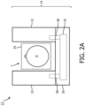
- FIGURES 2A-2C show another example embodiment of the radiation detector assembly 12.
- FIGURE 2A shows a "back" view of the radiation detector assembly.
- the radiation detector assembly 12 includes several radiation detectors 14, such as a back radiation detector 30 (e.g., positioned the same as the single radiation detector 14 depicted in FIGURE 1 ) and two side radiation detectors 32.
- the back radiation detector 30 and the two side radiation detectors 32 are arranged or otherwise configured to define a cavity C sized to receive the head H of the patient.
- the back radiation detector 30 is arranged to view a backside of the head disposed in the cavity C, and the two side radiation detectors 32 are arranged to view left and right sides of the head disposed in the cavity.
- the back radiation detector 30 and the two side radiation detectors 32 each have a planar radiation detecting surface (as illustrated). In another example, the back radiation detector 30 and the two side radiation detectors 32 have curved radiation detecting surfaces (not shown) which are shaped to conform with a shape of the head disposed in the cavity C. The side detectors 32, if provided, yield additional counts to enable further reduction in the administered radiopharmaceutical dosage.
- a crown radiation detector 34 (shown by dashed lines) is included to further define the cavity C and to provide still further counts, and arranged to view a crown (i.e. top) of the head H disposed in the cavity.
- the radiation detector assembly 12 further includes a radiation shielding collar 36 (see FIGURE 1 ) comprising a radiation-absorbing material (e.g. a high atomic weight material such as lead or a composite or other matrix containing a high atomic weight element such as leaded glass) and shaped and sized to be disposed around a portion (i.e., neck) of the patient.
- a radiation shielding collar 36 blocks stray radiation from the torso and/or other portions of the body from reaching the detector(s) 14 surrounding the head H, and also may serve to mechanically stabilize the head H.
- the radiation detector assembly 12 does not include robotic actuators configured for moving the radiation detectors 14 during a data acquisition time interval over which radiation counts are detected using the radiation detector assembly.
- adjustable supports 38 are attached to the side radiation detectors 32 and the patient support 14 to move and position the side radiation detectors at an adjustable distance from the cavity C.
- the radiation detector assembly 12 does not include a radiation collimator, nor does the device 10 include timestamping circuitry for assigning timestamps to radiation counts detected using the radiation detector assembly. (Note, however, that in contrast to timestamping individual counts, a test date may be assigned for an acquired data set of counts).
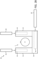
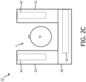
- either at least one radiation collimator plate 40 (see FIGURE 2B ) or coincidence detection circuitry 42 (see FIGURE 2C ) is included with the radiation detector assembly 12 collimate radiation detected by the radiation detectors 14. (More specifically, the collimator plate 40 passes to the coupled radiation detector only radiation travelling along a line or narrow-angle cone, so that the detected radiation is collimated).
- each of the back radiation detector 30 and the two side radiation detectors 32 has collimator mounting hardware 44 via which one of the radiation collimator plates is mountable to the planar radiation detecting surface.
- the radiation collimator plate 40 can include a slat or honeycomb radiation collimator plate
- the collimator mounting hardware 44 comprises a corresponding slit configured to receive and hold the slat or honeycomb collimator plate.
- the at least one electronic processor 20 can be programmed to reconstruct the detected radiation counts into an image (e.g., a one-dimensional image in the case of a slat collimator, or a two- or three-dimensional image in the case of a honeycomb collimator).
- Such image reconstruction can employ any suitable image reconstruction technique such as one conventionally employed in reconstructing SPECT imaging data.
- the radiotracer is a PET radiotracer that emits positrons that decay into oppositely directed 511 keV gamma rays
- coincidence detection can be employed in which coincident 511 keV detection events are detected using a suitable time window and each pair of 511 keV detections form a count.
- any conventional PET reconstruction technique can be employed to reconstruct the counts into an image.
- the radiation detector assembly 12 is configured to detect radiation counts emanating from at least one half of tissue of a brain monitored by the radiation detector assembly.
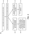
- the system 10 is configured to perform a method or process 100 for performing a beta amyloid (or other targeted amyloid or protein) assessment.
- the non-transitory storage medium 26 stores instructions which are readable and executable by the at least one electronic processor 20 of the workstation 18 to perform disclosed operations including performing the method or process 100 for performing a beta amyloid assessment.
- the method 100 may be performed at least in part by cloud processing.
- an illustrative embodiment of the method 100 for performing a beta amyloid assessment is diagrammatically shown as a flowchart.
- a patient is positioned (e.g., laid) on the patient support 16.
- a radiotracer is then administered to the patient while positioned on the patient support 16.
- the radiotracer may be administered prior to placement of the patient on the patient support; however, administering the radiotracer with the patient already positioned on the patient support can provide for more precise timing between the administration and the time interval for counts measurement).
- the at least one electronic processor 20 is programmed to control (or merely read, in some embodiments) the detectors 14 of the radiation detector assembly 12 to detect radiation counts over a data acquisition time interval.
- the detecting includes continuously detecting singles radiation counts from at least one-half of the brain (in some preferred embodiments, although monitoring a smaller portion of the brain is also contemplated) of the positioned patient over the data acquisition time interval.
- the singles radiation counts are detected without collimation of the radiation, and without determining and assigning timestamps to individual counts.
- the at least one electronic processor 20 is programmed to compute at least one current count metric from the detected radiation counts.
- the at least one current count metric includes at least one of a count rate and a total counts detected over the data acquisition time interval.
- the computing of the at least one current count metric includes scaling the at least one current count metric by one or more of patient weight, patient age, patient gender, and patient ethnicity. The scaling may be empirically determined, e.g. using a look-up table that applies a scaling factor on the basis of patient age, or a scaling factor proportional to patient weight, or so forth.
- the radioactivity of the radiotracer may be measured prior to administration to the patient or during administration (e.g.
- the count metric may be scaled proportional to the actually measured radioactivity of the radiotracer. This adjustment accounts for day-to-day variability in the injected dose of the radiotracer.
- the at least one electronic processor 20 is programmed to store the at least one current count metric associated with a current test date in the non-transitory storage medium 26.
- the test date is associated with the data set as a whole, as opposed to timestamps of individual radiation detection counts. As such it may optionally be of relatively low temporal resolution, e.g. storing the calendar date but not a time-of-day).
- the at least one electronic processor 20 is programmed to determine a beta amyloid metric based on a comparison of the at least one current count metric with a count metric stored in the non-transitory storage medium 26 associated with an earlier test date.
- the beta amyloid metric (or, more generally, the amyloid metric, or even more generally the metric of deposits of the targeted protein in the head H of the patient P ) may, for example, be a percent change between the current count metric and the count metric of the earlier test date.
- the at least one electronic processor 20 is programmed to generate a one-dimensional (1D) counts profile line from the measured total number of counts or the count rate, based on an image reconstructed from spatial localization of the events provided by a collimator in SPECT-type imaging, or by PET-type coincidence detection).
- the at least one electronic processor 20 is programmed to control the display 24 to display the beta amyloid metric and (if generated) the generated counts profile line having peaks at outer regions thereof and a trough at a center portion thereof. Other information may be displayed such as the current counts metric and the counts metric of the earlier test date. If there are two or more past tests stored in the non-transitory storage medium 26, then optionally one or more trend lines can be plotted, such as plotting the counts metric for each test as a function of test date. Display of such a trend line allows for the clinician to immediately visually perceive whether the counts metric (and, by inference, the beta amyloid deposits) have been increasing, and if so at what rate.
- beta amyloid metric and any other displayed metrics is merely clinical information for consideration, in conjunction with other information such as physical examination, inquiry into patient-reported symptoms such as level of mental recall, or so forth, by the clinician in assessing whether the patient P should be diagnosed as having Alzheimer's disease (or other disease associated with build-up of the targeted amyloid or protein in the brain).
- the beta amyloid metric (generated at 108 ) and/or the counts profile line (generated at 110 ) may be additionally or alternatively used in follow-up treatment of the patient. For example, if a medication is administered to suppress amyloid deposits, the patient may monitored during the medication treatment (e.g., using the beta amyloid assessment method 100 ) to determine the effectiveness of the medication regimen.
- the low radiopharmaceutical dosage and use of the system 10 allow for more frequent monitoring of the patient.
- beta amyloid metric and the counts profile line obtained by the system 10 can in alternative embodiment be acquired using a conventional PET imaging system, for example including coincidence detection circuitry and configured to perform image reconstruction.
- FIGURE 4 shows a hypothetical example of a generated counts profile (i.e. trend) line.
- an uptake (measured, for example, by a counts metric such as count rate or total counts) of an amyloid tracer can be compared over the time for successive test dates (e.g., tests may be performed every two years, e.g. in years 2018, 2020, 2022, 2024, and 2026 in the hypothetical example of FIGURE 4 ).
- a current test indicates a statistically significant increase in uptake (such as the test in year 2026 in hypothetical FIGURE 4 , which shows a relatively large increase over the result in year 2024 and preceding years)
- the patient may be referred to further tests, especially if he is in the risk group based on age, occupation or family history.
- Another test may be performed using the apparatus of FIGURE 1 after some period of time to confirm the trend. At least two repeated scans (e.g., with some gap in time) may be considered clinically significant so as to contribute (with other factors such as patient-reported mental acuity) to an amyloidosis risk assessment.
- the foregoing approach assumes that there are one or more past tests yielding past count metric(s) against which the count metric of the current test is compared.
- the first time the test is run on a given patient there will be no past results to compare against and so it will be difficult or impossible to draw clinically useful information from that first test in isolation.
- it is expected that clinical conclusions drawn from a trend of test results over several years is more likely to yield clinically meaningful information.
- the device 10 is configured to provide a low cost amyloid screening tool which makes large scale (e.g., population level) screening for the risk of amyloid accumulation available.
- the patient is injected with microdoses of amyloid specific radiotracer and, after the uptake time, the amount of radioactivity increase in patient head is assessed using, for example, a gamma camera to count the number of acquired single hits.
- the scan is repeated on an annual or clinician-prescribed basis, and the obtained singles count rates (and/or other count metric) for the current test are compared with the count rates for past tests to determine the trend for potential amyloid plaque accumulation. If the trend becomes positive (uptake increase in more recent tests), then the patient may be referred for further tests.
- Such proposed screening is affordable as inexpensive detectors can be used to measure the single rates, as well as only microcuries of the radioactivity may be used, as there is no need to create tomographic images.
- the device 10 is configured to increase affordability and reduce a radiation burden for the patient to make the amyloid screening as available as possible, comparable to other routine examinations such as dental and chest X-ray (0.1-0.005mSv), and much lower than even that for low-dose CT lung screening (1.5 mSv).
- a patient exam starts from injection of a small controlled amount of radioactive tracer that binds to amyloid plaque, e.g. florbetapir or flutemetamol. After an uptake period, the patient's head is being scanned on a nuclear medicine camera working in singles detection mode without collimation. Only the singles rate (or total number of singles needs to be recorded).
- the detectors 14 may optionally wrap around the patient's head with additional radiation sensitive blocks, as described for example with reference to FIGURES 2A-2C . Scanning in sitting or standing position is also contemplated. It is also advantageous to shield the detector part from the radioactivity coming from the rest of the body as much as possible, for example using the illustrative radiation shielding collar 36, and/or by placing a lead shirt over the patient during the examination, and/or so forth.
- the scan is repeated at the annual basis (or on other clinically established rate). It is advantageous to scale the obtained counts for the corresponding injected dose (that is, to scale by the radioactivity of the administered radiotracer) and to ensure that the uptake period and acquisition time are the same for each test, as well as use the same type of tracer (or employ conversion coefficient), to make the scan series directly comparable. Alternatively, if these factors cannot be made constant (for example, if the radiotracer used in a previous test becomes unavailable) then appropriate scaling of the count metric(s) may be employed based on empirical information.
- Normal aging may also result in increased plaque deposition potentially leading to false positives, and this again may optionally be accounted for by scaling the count metric(s). It is also beneficial to start the testing early enough to provide a baseline of the count metric(s) during the healthy uptake period before amyloid deposits start to build up in brain tissue. It may be especially beneficial to start this tracking and do it more often for patients in certain occupations, such as professional football players, as increased beta-amyloid plaque deposition has been linked to CTE as well.
- Machine learning techniques may optionally be employed to determine and empirically quantify the impact of factors and variables (e.g. age, gender, ethnicity, and so forth) that may impact the screening quantification so as to reduce the risk of false-positives.
- factors and variables e.g. age, gender, ethnicity, and so forth
- BMI body mass index
- each screening test be performed using the same camera or detector 14. If this is not possible, then a different camera may be used, but a sensitivity conversion factor between two cameras is preferably applied to ensure reproducibility and agreement in measurements.
- the device 10 may use low cost radiation detection electronics with sufficient stopping power, in one example, a Bismuth Germanate Oxide (BGO) detector may be used for this purpose.
- BGO Bismuth Germanate Oxide
- No coincidence mode is necessary unless PET imaging is desired as an option, and therefore a sensitivity increase is contemplated due to singles detection mode and close positioning of the subject to the detectors 14.
- there is no requirement such as "minimum detected counts per image voxel" as it is in the case with conventional PET or SPECT systems.
- attenuation in the brain remains nearly constant throughout the life of the patient, no CT acquisition or other source for an attenuation map is needed either. Rather, the impact of attenuation in the head H of the patient P is automatically accounted for by generating the amyloid metric based on comparison of the current count metric(s) with past count metric(s) from past tests performed on the same patient P.
- the resulting signal noise (per a Poisson process) would only constitute less than 0.5% of the signal. This means that only microCi levels of dose injections of amyloid tracer are needed, leading to a more than 1000x dose reduction as compared to conventional PET, and making the scan comparable to dental X-ray exams in terms of radiation burden.
Landscapes
- Health & Medical Sciences (AREA)
- Life Sciences & Earth Sciences (AREA)
- Engineering & Computer Science (AREA)
- Medical Informatics (AREA)
- Public Health (AREA)
- Pathology (AREA)
- General Health & Medical Sciences (AREA)
- Biomedical Technology (AREA)
- Molecular Biology (AREA)
- Animal Behavior & Ethology (AREA)
- Veterinary Medicine (AREA)
- Nuclear Medicine, Radiotherapy & Molecular Imaging (AREA)
- Optics & Photonics (AREA)
- Biophysics (AREA)
- Radiology & Medical Imaging (AREA)
- High Energy & Nuclear Physics (AREA)
- Heart & Thoracic Surgery (AREA)
- Physics & Mathematics (AREA)
- Surgery (AREA)
- Dentistry (AREA)
- Oral & Maxillofacial Surgery (AREA)
- Neurology (AREA)
- Neurosurgery (AREA)
- Physiology (AREA)
- Computer Vision & Pattern Recognition (AREA)
- Data Mining & Analysis (AREA)
- Databases & Information Systems (AREA)
- Epidemiology (AREA)
- Primary Health Care (AREA)
- Nuclear Medicine (AREA)
Claims (15)
- Un dispositif (10) pour effectuer une évaluation de l'amyloïde, le dispositif comprenant:un assemblage de détecteurs de rayonnement (12) comprenant au moins un détecteur de rayonnement (14);et au moins un processeur électronique (20) programmé pour:détecter les comptages de rayonnement sur un intervalle de temps d'acquisition de données à l'aide de l'ensemble du détecteur de rayonnement;calculer au moins une métrique de comptage actuelle à partir des comptages de rayonnement détectés;stocker au moins une métrique de comptage actuelle associée à une date de test actuelle dans un support de stockage non transitoire (26); etdéterminer une métrique amyloïde fondée sur une comparaison d'au moins une métrique de comptage actuelle avec une métrique de comptage stockée dans le support de stockage non transitoire associée à une date de test antérieure; et dans lequel:au moins une mesure de comptage actuelle comprend au moins un taux de comptage et un nombre total de comptages détectés au cours de l'intervalle de temps d'acquisition des données; etle calcul d'au moins une mesure de comptage actuelle comprend la mise à l'échelle d'au moins une mesure de comptage actuelle en fonction d'un ou plusieurs facteurs parmi le poids du patient, l'âge du patient, le sexe du patient et l'origine ethnique du patient.
- Le dispositif (10) de la revendication 1 dans lequel l'assemblage du détecteur de rayonnement (12) comprend en outre:
un collier de protection contre les rayonnements (36) composé d'un matériau absorbant les rayonnements et dont, la forme et la taille permettent de le placer autour d'un cou. - Le dispositif (10) de l'une des revendications 1 à 2 dans lequel l'assemblage du détecteur de rayonnement (12) comprend:un détecteur de rayonnement arrière (30);et deux détecteurs de rayonnement latéraux (32); dans lequel le détecteur de rayonnement arrière et les deux détecteurs de rayonnement latéraux sont disposés pour définir une cavité (C) dimensionnée pour recevoir une tête avec le détecteur de rayonnement arrière disposé pour voir un côté arrière de la tête disposée dans la cavité et les deux détecteurs de rayonnement latéraux disposé pour voir les côtés gauche et droit de la tête disposée dans la cavité.
- Le dispositif (10) de la revendication 3, dans lequel l'assemblage de détecteur de rayonnement (12) comprend en outre:
un détecteur de rayonnement de couronne (34) conçu pour définir davantage la cavité (C), le détecteur de rayonnement de couronne étant conçu pour visualiser une couronne de la tête disposée dans la cavité. - Le dispositif (10) de l'une des revendications 1 à 4 dans lequel:l'assemblage du détecteur de rayonnement (12) ne comprend pas de collimateur de rayonnement;et le dispositif ne comprend pas de circuit d'horodatage pour attribuer des horodatages aux comptages de rayonnement détectés à l'aide de l'assemblage du détecteur de rayonnement;et le calcul d'au moins une métrique de comptage actuel à partir des comptages de rayonnement détectés ne comprend pas de reconstruction d'image sur les comptages de rayonnement détectés.
- Le dispositif (10) de l'une des revendications 1 à 4 dans lequel:l'assemblage du détecteur de rayonnement (12) comprend (i) au moins un collimateur de rayonnement (40) ou (ii) un circuit de détection de coïncidence (42) pour acquérir les comptes de rayonnement en tant que comptes de coïncidence de rayonnement;au moins un processeur électronique (20) est en outre programmé pour reconstruire les comptes de rayonnement détectés en une image.
- Le dispositif (10) de l'une des revendications 1 à 4 dans lequel:l'assemblage du détecteur de rayonnement (12) comprend au moins un collimateur de rayonnement à lamelles (40) ;et au moins un processeur électronique (20) est en outre programmé pour reconstruire les comptes de rayonnement détectés en une image unidimensionnelle.
- Le dispositif (10) de l'une des revendications 1 à 7 dans lequel:l'assemblage du détecteur de rayonnement (12) ne comprend pas d'actionneurs robotiques configurés pour déplacer au moins un détecteur de rayonnement pendant l'intervalle de temps d'acquisition des données au cours duquel des comptages de rayonnement sont détectés à l'aide de l'assemblage du détecteur de rayonnement.
- Le dispositif (10) de l'une des revendications 1 à 8 dans lequel l'assemblage du détecteur de rayonnement (12) est configuré pour détecter les comptes de rayonnement émanant d'au moins la moitié d'un cerveau surveillé par l'assemblage du détecteur de rayonnement.
- Une méthode (100) pour effectuer une évaluation clinique, la méthode comprenant:l'obtention de données d'imagerie à l'aide d'un ensemble de détecteurs de rayonnement (12) comprenant au moins un détecteur de rayonnement (14) monté dans ou sur un support de patient sur lequel le patient est positionné pour voir la tête du patient positionné;la détection des comptes de rayonnement d'un radiotraceur administré au patient qui se lie à une protéine ciblée sur un intervalle de temps d'acquisition de données;le calcul d'au moins une métrique de comptage actuelle à partir des comptes de rayonnement détectés;et la détermination d'une métrique de dépôts de la protéine ciblée dans la tête du patient positionné sur la base d'une comparaison d'au moins une métrique de comptage actuelle avec une métrique de comptage précédente; etdans laquelle:au moins une mesure de comptage actuelle comprend au moins un taux de comptage et un nombre total de comptages détectés au cours de l'intervalle de temps d'acquisition des données;et caractérisé par le fait que le calcul d'au moins une mesure de comptage actuelle comprend la mise à l'échelle d'au moins une mesure de comptage actuelle en fonction d'un ou de plusieurs facteurs parmi le poids du patient, l'âge du patient, le sexe du patient et l'origine ethnique du patient.
- La méthode de la revendication 10, comprenant en outre:
la réalisation d'une évaluation de suivi du patient à l'aide de la métrique déterminée des dépôts. - La méthode de l'une des revendications 10 et 11, comprenant en outre:la génération d'une ligne de profil de comptage unidimensionnel (1D) à partir du nombre total de comptages mesurés ou du taux de comptage;et la commande d'un écran (24) pour afficher la ligne de profil de comptage générée.
- La méthode de l'une des revendications 10 et 11, dans laquelle la détection comprend la détection en continu des comptages de rayonnements singuliers provenant d'au moins la moitié du cerveau du patient positionné au cours de l'intervalle de temps d'acquisition des données.
- La méthode de la revendication 13, dans laquelle les comptages de rayonnements singuliers sont détectés sans collimation du rayonnement.
- La méthode de l'une des revendications 10 à 14, dans laquelle la protéine ciblée comprend le bêtaamyloïde.
Applications Claiming Priority (2)
| Application Number | Priority Date | Filing Date | Title |
|---|---|---|---|
| US201862720151P | 2018-08-21 | 2018-08-21 | |
| PCT/EP2019/071702 WO2020038773A1 (fr) | 2018-08-21 | 2019-08-13 | Procédé et appareil de dépistage d'amyloïde |
Publications (2)
| Publication Number | Publication Date |
|---|---|
| EP3840652A1 EP3840652A1 (fr) | 2021-06-30 |
| EP3840652B1 true EP3840652B1 (fr) | 2024-02-28 |
Family
ID=67660534
Family Applications (1)
| Application Number | Title | Priority Date | Filing Date |
|---|---|---|---|
| EP19755573.3A Active EP3840652B1 (fr) | 2018-08-21 | 2019-08-13 | Procédé et appareil de dépistage d'amyloïde |
Country Status (5)
| Country | Link |
|---|---|
| US (1) | US11806182B2 (fr) |
| EP (1) | EP3840652B1 (fr) |
| JP (2) | JP7442505B2 (fr) |
| CN (1) | CN112584767A (fr) |
| WO (1) | WO2020038773A1 (fr) |
Families Citing this family (2)
| Publication number | Priority date | Publication date | Assignee | Title |
|---|---|---|---|---|
| JP7503996B2 (ja) * | 2020-10-15 | 2024-06-21 | キヤノンメディカルシステムズ株式会社 | 核医学診断装置および医用情報処理装置 |
| KR20230093099A (ko) * | 2021-12-17 | 2023-06-27 | 사회복지법인 삼성생명공익재단 | 베타 아밀로이드 양성 전환 대상자 예측장치 |
Family Cites Families (19)
| Publication number | Priority date | Publication date | Assignee | Title |
|---|---|---|---|---|
| GB9323826D0 (en) | 1993-11-19 | 1994-01-05 | Royal Postgrad Med School | Diagnosis of alzheimer's disease |
| US6603123B1 (en) | 2000-11-08 | 2003-08-05 | Koninklijke Philips Electronics, N.V. | Correction for depth-dependent sensitivity in rotating slat-collimated gamma camera |
| US6808308B2 (en) * | 2001-05-25 | 2004-10-26 | Scanwell Systems | Removable shielding for use during neurological examinations on a whole body pet scanner |
| WO2003001881A2 (fr) | 2001-06-26 | 2003-01-09 | New York State Office Of Mental Health | Procedures cellulaires de recherche systematique a haut rendement |
| US7720524B2 (en) | 2006-07-04 | 2010-05-18 | Shyam Mohan Srinivas | Method, apparatus, and system for detecting disease states in a living body using a gamma ray counter |
| EP2247944A1 (fr) * | 2008-02-27 | 2010-11-10 | Avid Radiopharmaceuticals, Inc. | Détection par sonde gamma de plaques amyloïdes utilisant des composés de liaison a-bêta radiomarqués |
| US20100001192A1 (en) | 2008-07-07 | 2010-01-07 | Kai Lange | Gamma camera system with slanted detectors, slanted collimators, and a support hood |
| US20100145194A1 (en) * | 2008-11-13 | 2010-06-10 | Avid Radiopharmaceuticals, Inc. | Histogram-based analysis method for the detection and diagnosis of neurodegenerative diseases |
| JP5254076B2 (ja) * | 2009-02-24 | 2013-08-07 | 株式会社東芝 | ポジトロンct装置 |
| JP2013521233A (ja) * | 2010-02-25 | 2013-06-10 | ヤンセン アルツハイマー イミュノセラピー | Aβを標的とする免疫療法のPETモニタリング |
| FR2969153B1 (fr) | 2010-12-17 | 2014-10-17 | Lab Francais Du Fractionnement | Procede de purification de proteine amyloide p et utilisation de la proteine ainsi purifiee |
| WO2012149607A1 (fr) | 2011-05-03 | 2012-11-08 | Commonwealth Scientific And Industrial Research Organisation | Méthode de détection de maladie neurologique |
| RU2014125065A (ru) * | 2011-11-22 | 2015-12-27 | Конинклейке Филипс Н.В. | Бесплатформенная система однофотонной эмиссионной компьютерной томографии |
| EP2967339B1 (fr) * | 2013-03-15 | 2019-11-20 | Biogen MA Inc. | Evaluation de sondes étiquetées dans un sujet |
| US10433802B2 (en) * | 2013-06-07 | 2019-10-08 | Koninklijke Philips N.V. | Amyloid PET brain scan quantification based on cortical profiles |
| JP2015222193A (ja) * | 2014-05-22 | 2015-12-10 | 株式会社島津製作所 | 放射線測定装置 |
| US10751019B2 (en) * | 2015-09-16 | 2020-08-25 | Adm Diagnostics, Inc. | Determining a brain condition using early time frame PET image analysis |
| WO2018064715A1 (fr) * | 2016-10-03 | 2018-04-12 | Crc For Mental Health Ltd | Procédé pour la prédiction ou le diagnostic d'une détérioration cognitive |
| US11660054B2 (en) * | 2016-11-22 | 2023-05-30 | Biogen Ma Inc. | Medical diagnostic and treatment systems and their methods of use |
-
2019
- 2019-08-13 CN CN201980054616.8A patent/CN112584767A/zh active Pending
- 2019-08-13 US US17/270,224 patent/US11806182B2/en active Active
- 2019-08-13 JP JP2021509908A patent/JP7442505B2/ja active Active
- 2019-08-13 EP EP19755573.3A patent/EP3840652B1/fr active Active
- 2019-08-13 WO PCT/EP2019/071702 patent/WO2020038773A1/fr not_active Ceased
-
2023
- 2023-12-12 JP JP2023208952A patent/JP2024023625A/ja not_active Withdrawn
Also Published As
| Publication number | Publication date |
|---|---|
| US20210298701A1 (en) | 2021-09-30 |
| JP2024023625A (ja) | 2024-02-21 |
| US11806182B2 (en) | 2023-11-07 |
| WO2020038773A1 (fr) | 2020-02-27 |
| JP2021535378A (ja) | 2021-12-16 |
| CN112584767A (zh) | 2021-03-30 |
| EP3840652A1 (fr) | 2021-06-30 |
| JP7442505B2 (ja) | 2024-03-04 |
Similar Documents
| Publication | Publication Date | Title |
|---|---|---|
| Lassmann et al. | EANM Dosimetry Committee series on standard operational procedures for pre-therapeutic dosimetry I: blood and bone marrow dosimetry in differentiated thyroid cancer therapy | |
| US10820880B2 (en) | Method and apparatus for sensitivity calibration | |
| KR101121791B1 (ko) | 핵의학 진단장치 및 그것에 이용되는 진단시스템 | |
| JP2024023625A (ja) | アミロイドスクリーニング方法及び装置 | |
| JP2022523881A (ja) | 限局放射線の時間的測定を使用して体内の放射性物質の大きさ、位置、および体積を推定するシステムおよび方法 | |
| US20100331676A1 (en) | Gamma probe detection of amyloid plaque using radiolabeled a-beta binding compounds | |
| Alramlawy et al. | Effective radiation dose to staff members due to myocardial perfusion spect imaging: tracking the exposure from preparation to patient release | |
| US8374681B2 (en) | Apparatus and method for functional neurological screening with adjustable spaced collimator plates | |
| Miles et al. | An introduction to attenuation correction | |
| JP4656008B2 (ja) | 核医学診断装置 | |
| McCormick et al. | Radiation dose to positron emission tomography technologists during quantitative versus qualitative studies | |
| Turkington et al. | Clinical oncologic positron emission tomography: an introduction | |
| Phelps et al. | Design considerations in positron computed tomography (PCT) | |
| Morin et al. | 169Yb-DTPA distribution and dosimetry in cisternography | |
| Fulcheri et al. | State-of-the-art 32 cm field-of-view digital PET/CT system: preliminary study for protocols optimization and DRLs update | |
| Walker et al. | PET neuroimaging of neurologic disease: Methods and clinical and research applications. | |
| Zhang et al. | Nuclear Medicine and Molecular Imaging | |
| Logan | Quantitative SPECT imaging for diagnosis and dosimetry in radionuclide therapy | |
| Stiles et al. | Evaluation of High-Sensitivity Organ-Specific Positron Emission Tomography (PET) System | |
| Aye | Local diagnostic reference level at Nuclear Medicine Centers in Thailand and Myanmar | |
| Gülaldi et al. | Optimization of SUV with Changing the Dose Amount in F18-FDG PET/CT of Pediatric Lymphoma Patients | |
| Design | Physics of Positrons, 364 Production of Positron Emission Tomography Radiotracers, 365 Coincidence Detection in Positron Emission Tomography, 366 | |
| Kubo et al. | Image Formation in Nuclear Medicine | |
| Kanno | Pet Instrumentation for Quantitative Tracing of Radiopharmaceuticals | |
| dos Anjos Silva et al. | Image Formation in Nuclear |
Legal Events
| Date | Code | Title | Description |
|---|---|---|---|
| STAA | Information on the status of an ep patent application or granted ep patent |
Free format text: STATUS: UNKNOWN |
|
| STAA | Information on the status of an ep patent application or granted ep patent |
Free format text: STATUS: THE INTERNATIONAL PUBLICATION HAS BEEN MADE |
|
| PUAI | Public reference made under article 153(3) epc to a published international application that has entered the european phase |
Free format text: ORIGINAL CODE: 0009012 |
|
| STAA | Information on the status of an ep patent application or granted ep patent |
Free format text: STATUS: REQUEST FOR EXAMINATION WAS MADE |
|
| 17P | Request for examination filed |
Effective date: 20210322 |
|
| AK | Designated contracting states |
Kind code of ref document: A1 Designated state(s): AL AT BE BG CH CY CZ DE DK EE ES FI FR GB GR HR HU IE IS IT LI LT LU LV MC MK MT NL NO PL PT RO RS SE SI SK SM TR |
|
| DAV | Request for validation of the european patent (deleted) | ||
| DAX | Request for extension of the european patent (deleted) | ||
| GRAP | Despatch of communication of intention to grant a patent |
Free format text: ORIGINAL CODE: EPIDOSNIGR1 |
|
| STAA | Information on the status of an ep patent application or granted ep patent |
Free format text: STATUS: GRANT OF PATENT IS INTENDED |
|
| RIC1 | Information provided on ipc code assigned before grant |
Ipc: G16H 50/30 20180101ALI20230901BHEP Ipc: G06T 7/00 20170101ALI20230901BHEP Ipc: G06T 7/33 20170101ALI20230901BHEP Ipc: A61B 6/04 20060101ALI20230901BHEP Ipc: A61B 6/00 20060101ALI20230901BHEP Ipc: A61B 6/03 20060101AFI20230901BHEP |
|
| INTG | Intention to grant announced |
Effective date: 20230929 |
|
| GRAS | Grant fee paid |
Free format text: ORIGINAL CODE: EPIDOSNIGR3 |
|
| GRAA | (expected) grant |
Free format text: ORIGINAL CODE: 0009210 |
|
| STAA | Information on the status of an ep patent application or granted ep patent |
Free format text: STATUS: THE PATENT HAS BEEN GRANTED |
|
| AK | Designated contracting states |
Kind code of ref document: B1 Designated state(s): AL AT BE BG CH CY CZ DE DK EE ES FI FR GB GR HR HU IE IS IT LI LT LU LV MC MK MT NL NO PL PT RO RS SE SI SK SM TR |
|
| REG | Reference to a national code |
Ref country code: GB Ref legal event code: FG4D |
|
| REG | Reference to a national code |
Ref country code: CH Ref legal event code: EP |
|
| REG | Reference to a national code |
Ref country code: DE Ref legal event code: R096 Ref document number: 602019047350 Country of ref document: DE |
|
| REG | Reference to a national code |
Ref country code: IE Ref legal event code: FG4D |
|
| REG | Reference to a national code |
Ref country code: DE Ref legal event code: R084 Ref document number: 602019047350 Country of ref document: DE |
|
| REG | Reference to a national code |
Ref country code: GB Ref legal event code: 746 Effective date: 20240417 |
|
| REG | Reference to a national code |
Ref country code: LT Ref legal event code: MG9D |
|
| PG25 | Lapsed in a contracting state [announced via postgrant information from national office to epo] |
Ref country code: IS Free format text: LAPSE BECAUSE OF FAILURE TO SUBMIT A TRANSLATION OF THE DESCRIPTION OR TO PAY THE FEE WITHIN THE PRESCRIBED TIME-LIMIT Effective date: 20240628 |
|
| REG | Reference to a national code |
Ref country code: NL Ref legal event code: MP Effective date: 20240228 |
|
| PG25 | Lapsed in a contracting state [announced via postgrant information from national office to epo] |
Ref country code: LT Free format text: LAPSE BECAUSE OF FAILURE TO SUBMIT A TRANSLATION OF THE DESCRIPTION OR TO PAY THE FEE WITHIN THE PRESCRIBED TIME-LIMIT Effective date: 20240228 |
|
| PG25 | Lapsed in a contracting state [announced via postgrant information from national office to epo] |
Ref country code: GR Free format text: LAPSE BECAUSE OF FAILURE TO SUBMIT A TRANSLATION OF THE DESCRIPTION OR TO PAY THE FEE WITHIN THE PRESCRIBED TIME-LIMIT Effective date: 20240529 |
|
| PG25 | Lapsed in a contracting state [announced via postgrant information from national office to epo] |
Ref country code: HR Free format text: LAPSE BECAUSE OF FAILURE TO SUBMIT A TRANSLATION OF THE DESCRIPTION OR TO PAY THE FEE WITHIN THE PRESCRIBED TIME-LIMIT Effective date: 20240228 Ref country code: RS Free format text: LAPSE BECAUSE OF FAILURE TO SUBMIT A TRANSLATION OF THE DESCRIPTION OR TO PAY THE FEE WITHIN THE PRESCRIBED TIME-LIMIT Effective date: 20240528 Ref country code: NL Free format text: LAPSE BECAUSE OF FAILURE TO SUBMIT A TRANSLATION OF THE DESCRIPTION OR TO PAY THE FEE WITHIN THE PRESCRIBED TIME-LIMIT Effective date: 20240228 |
|
| PG25 | Lapsed in a contracting state [announced via postgrant information from national office to epo] |
Ref country code: ES Free format text: LAPSE BECAUSE OF FAILURE TO SUBMIT A TRANSLATION OF THE DESCRIPTION OR TO PAY THE FEE WITHIN THE PRESCRIBED TIME-LIMIT Effective date: 20240228 |
|
| PG25 | Lapsed in a contracting state [announced via postgrant information from national office to epo] |
Ref country code: RS Free format text: LAPSE BECAUSE OF FAILURE TO SUBMIT A TRANSLATION OF THE DESCRIPTION OR TO PAY THE FEE WITHIN THE PRESCRIBED TIME-LIMIT Effective date: 20240528 Ref country code: NO Free format text: LAPSE BECAUSE OF FAILURE TO SUBMIT A TRANSLATION OF THE DESCRIPTION OR TO PAY THE FEE WITHIN THE PRESCRIBED TIME-LIMIT Effective date: 20240528 Ref country code: NL Free format text: LAPSE BECAUSE OF FAILURE TO SUBMIT A TRANSLATION OF THE DESCRIPTION OR TO PAY THE FEE WITHIN THE PRESCRIBED TIME-LIMIT Effective date: 20240228 Ref country code: LT Free format text: LAPSE BECAUSE OF FAILURE TO SUBMIT A TRANSLATION OF THE DESCRIPTION OR TO PAY THE FEE WITHIN THE PRESCRIBED TIME-LIMIT Effective date: 20240228 Ref country code: IS Free format text: LAPSE BECAUSE OF FAILURE TO SUBMIT A TRANSLATION OF THE DESCRIPTION OR TO PAY THE FEE WITHIN THE PRESCRIBED TIME-LIMIT Effective date: 20240628 Ref country code: HR Free format text: LAPSE BECAUSE OF FAILURE TO SUBMIT A TRANSLATION OF THE DESCRIPTION OR TO PAY THE FEE WITHIN THE PRESCRIBED TIME-LIMIT Effective date: 20240228 Ref country code: GR Free format text: LAPSE BECAUSE OF FAILURE TO SUBMIT A TRANSLATION OF THE DESCRIPTION OR TO PAY THE FEE WITHIN THE PRESCRIBED TIME-LIMIT Effective date: 20240529 Ref country code: FI Free format text: LAPSE BECAUSE OF FAILURE TO SUBMIT A TRANSLATION OF THE DESCRIPTION OR TO PAY THE FEE WITHIN THE PRESCRIBED TIME-LIMIT Effective date: 20240228 Ref country code: ES Free format text: LAPSE BECAUSE OF FAILURE TO SUBMIT A TRANSLATION OF THE DESCRIPTION OR TO PAY THE FEE WITHIN THE PRESCRIBED TIME-LIMIT Effective date: 20240228 Ref country code: BG Free format text: LAPSE BECAUSE OF FAILURE TO SUBMIT A TRANSLATION OF THE DESCRIPTION OR TO PAY THE FEE WITHIN THE PRESCRIBED TIME-LIMIT Effective date: 20240228 |
|
| PG25 | Lapsed in a contracting state [announced via postgrant information from national office to epo] |
Ref country code: PT Free format text: LAPSE BECAUSE OF FAILURE TO SUBMIT A TRANSLATION OF THE DESCRIPTION OR TO PAY THE FEE WITHIN THE PRESCRIBED TIME-LIMIT Effective date: 20240628 Ref country code: PL Free format text: LAPSE BECAUSE OF FAILURE TO SUBMIT A TRANSLATION OF THE DESCRIPTION OR TO PAY THE FEE WITHIN THE PRESCRIBED TIME-LIMIT Effective date: 20240228 |
|
| REG | Reference to a national code |
Ref country code: AT Ref legal event code: MK05 Ref document number: 1660453 Country of ref document: AT Kind code of ref document: T Effective date: 20240228 |
|
| PG25 | Lapsed in a contracting state [announced via postgrant information from national office to epo] |
Ref country code: SE Free format text: LAPSE BECAUSE OF FAILURE TO SUBMIT A TRANSLATION OF THE DESCRIPTION OR TO PAY THE FEE WITHIN THE PRESCRIBED TIME-LIMIT Effective date: 20240228 Ref country code: PT Free format text: LAPSE BECAUSE OF FAILURE TO SUBMIT A TRANSLATION OF THE DESCRIPTION OR TO PAY THE FEE WITHIN THE PRESCRIBED TIME-LIMIT Effective date: 20240628 Ref country code: PL Free format text: LAPSE BECAUSE OF FAILURE TO SUBMIT A TRANSLATION OF THE DESCRIPTION OR TO PAY THE FEE WITHIN THE PRESCRIBED TIME-LIMIT Effective date: 20240228 Ref country code: LV Free format text: LAPSE BECAUSE OF FAILURE TO SUBMIT A TRANSLATION OF THE DESCRIPTION OR TO PAY THE FEE WITHIN THE PRESCRIBED TIME-LIMIT Effective date: 20240228 |
|
| PG25 | Lapsed in a contracting state [announced via postgrant information from national office to epo] |
Ref country code: DK Free format text: LAPSE BECAUSE OF FAILURE TO SUBMIT A TRANSLATION OF THE DESCRIPTION OR TO PAY THE FEE WITHIN THE PRESCRIBED TIME-LIMIT Effective date: 20240228 |
|
| PG25 | Lapsed in a contracting state [announced via postgrant information from national office to epo] |
Ref country code: SM Free format text: LAPSE BECAUSE OF FAILURE TO SUBMIT A TRANSLATION OF THE DESCRIPTION OR TO PAY THE FEE WITHIN THE PRESCRIBED TIME-LIMIT Effective date: 20240228 |
|
| PG25 | Lapsed in a contracting state [announced via postgrant information from national office to epo] |
Ref country code: EE Free format text: LAPSE BECAUSE OF FAILURE TO SUBMIT A TRANSLATION OF THE DESCRIPTION OR TO PAY THE FEE WITHIN THE PRESCRIBED TIME-LIMIT Effective date: 20240228 Ref country code: CZ Free format text: LAPSE BECAUSE OF FAILURE TO SUBMIT A TRANSLATION OF THE DESCRIPTION OR TO PAY THE FEE WITHIN THE PRESCRIBED TIME-LIMIT Effective date: 20240228 |
|
| PG25 | Lapsed in a contracting state [announced via postgrant information from national office to epo] |
Ref country code: AT Free format text: LAPSE BECAUSE OF FAILURE TO SUBMIT A TRANSLATION OF THE DESCRIPTION OR TO PAY THE FEE WITHIN THE PRESCRIBED TIME-LIMIT Effective date: 20240228 |
|
| PG25 | Lapsed in a contracting state [announced via postgrant information from national office to epo] |
Ref country code: SK Free format text: LAPSE BECAUSE OF FAILURE TO SUBMIT A TRANSLATION OF THE DESCRIPTION OR TO PAY THE FEE WITHIN THE PRESCRIBED TIME-LIMIT Effective date: 20240228 |
|
| PG25 | Lapsed in a contracting state [announced via postgrant information from national office to epo] |
Ref country code: SM Free format text: LAPSE BECAUSE OF FAILURE TO SUBMIT A TRANSLATION OF THE DESCRIPTION OR TO PAY THE FEE WITHIN THE PRESCRIBED TIME-LIMIT Effective date: 20240228 Ref country code: SK Free format text: LAPSE BECAUSE OF FAILURE TO SUBMIT A TRANSLATION OF THE DESCRIPTION OR TO PAY THE FEE WITHIN THE PRESCRIBED TIME-LIMIT Effective date: 20240228 Ref country code: RO Free format text: LAPSE BECAUSE OF FAILURE TO SUBMIT A TRANSLATION OF THE DESCRIPTION OR TO PAY THE FEE WITHIN THE PRESCRIBED TIME-LIMIT Effective date: 20240228 Ref country code: EE Free format text: LAPSE BECAUSE OF FAILURE TO SUBMIT A TRANSLATION OF THE DESCRIPTION OR TO PAY THE FEE WITHIN THE PRESCRIBED TIME-LIMIT Effective date: 20240228 Ref country code: DK Free format text: LAPSE BECAUSE OF FAILURE TO SUBMIT A TRANSLATION OF THE DESCRIPTION OR TO PAY THE FEE WITHIN THE PRESCRIBED TIME-LIMIT Effective date: 20240228 Ref country code: CZ Free format text: LAPSE BECAUSE OF FAILURE TO SUBMIT A TRANSLATION OF THE DESCRIPTION OR TO PAY THE FEE WITHIN THE PRESCRIBED TIME-LIMIT Effective date: 20240228 Ref country code: AT Free format text: LAPSE BECAUSE OF FAILURE TO SUBMIT A TRANSLATION OF THE DESCRIPTION OR TO PAY THE FEE WITHIN THE PRESCRIBED TIME-LIMIT Effective date: 20240228 |
|
| REG | Reference to a national code |
Ref country code: DE Ref legal event code: R097 Ref document number: 602019047350 Country of ref document: DE |
|
| PG25 | Lapsed in a contracting state [announced via postgrant information from national office to epo] |
Ref country code: IT Free format text: LAPSE BECAUSE OF FAILURE TO SUBMIT A TRANSLATION OF THE DESCRIPTION OR TO PAY THE FEE WITHIN THE PRESCRIBED TIME-LIMIT Effective date: 20240228 |
|
| PG25 | Lapsed in a contracting state [announced via postgrant information from national office to epo] |
Ref country code: IT Free format text: LAPSE BECAUSE OF FAILURE TO SUBMIT A TRANSLATION OF THE DESCRIPTION OR TO PAY THE FEE WITHIN THE PRESCRIBED TIME-LIMIT Effective date: 20240228 |
|
| PLBE | No opposition filed within time limit |
Free format text: ORIGINAL CODE: 0009261 |
|
| STAA | Information on the status of an ep patent application or granted ep patent |
Free format text: STATUS: NO OPPOSITION FILED WITHIN TIME LIMIT |
|
| 26N | No opposition filed |
Effective date: 20241129 |
|
| REG | Reference to a national code |
Ref country code: DE Ref legal event code: R119 Ref document number: 602019047350 Country of ref document: DE |
|
| REG | Reference to a national code |
Ref country code: CH Ref legal event code: PL |
|
| PG25 | Lapsed in a contracting state [announced via postgrant information from national office to epo] |
Ref country code: LU Free format text: LAPSE BECAUSE OF NON-PAYMENT OF DUE FEES Effective date: 20240813 |
|
| GBPC | Gb: european patent ceased through non-payment of renewal fee |
Effective date: 20240813 |
|
| PG25 | Lapsed in a contracting state [announced via postgrant information from national office to epo] |
Ref country code: CH Free format text: LAPSE BECAUSE OF NON-PAYMENT OF DUE FEES Effective date: 20240831 Ref country code: SI Free format text: LAPSE BECAUSE OF FAILURE TO SUBMIT A TRANSLATION OF THE DESCRIPTION OR TO PAY THE FEE WITHIN THE PRESCRIBED TIME-LIMIT Effective date: 20240228 Ref country code: MC Free format text: LAPSE BECAUSE OF FAILURE TO SUBMIT A TRANSLATION OF THE DESCRIPTION OR TO PAY THE FEE WITHIN THE PRESCRIBED TIME-LIMIT Effective date: 20240228 |
|
| REG | Reference to a national code |
Ref country code: BE Ref legal event code: MM Effective date: 20240831 |
|
| PG25 | Lapsed in a contracting state [announced via postgrant information from national office to epo] |
Ref country code: DE Free format text: LAPSE BECAUSE OF NON-PAYMENT OF DUE FEES Effective date: 20250301 |
|
| PG25 | Lapsed in a contracting state [announced via postgrant information from national office to epo] |
Ref country code: GB Free format text: LAPSE BECAUSE OF NON-PAYMENT OF DUE FEES Effective date: 20240813 |
|
| PG25 | Lapsed in a contracting state [announced via postgrant information from national office to epo] |
Ref country code: BE Free format text: LAPSE BECAUSE OF NON-PAYMENT OF DUE FEES Effective date: 20240831 |
|
| PG25 | Lapsed in a contracting state [announced via postgrant information from national office to epo] |
Ref country code: FR Free format text: LAPSE BECAUSE OF NON-PAYMENT OF DUE FEES Effective date: 20240831 |
|
| PG25 | Lapsed in a contracting state [announced via postgrant information from national office to epo] |
Ref country code: IE Free format text: LAPSE BECAUSE OF NON-PAYMENT OF DUE FEES Effective date: 20240813 |
|
| PG25 | Lapsed in a contracting state [announced via postgrant information from national office to epo] |
Ref country code: CY Free format text: LAPSE BECAUSE OF FAILURE TO SUBMIT A TRANSLATION OF THE DESCRIPTION OR TO PAY THE FEE WITHIN THE PRESCRIBED TIME-LIMIT; INVALID AB INITIO Effective date: 20190813 |
|
| PG25 | Lapsed in a contracting state [announced via postgrant information from national office to epo] |
Ref country code: HU Free format text: LAPSE BECAUSE OF FAILURE TO SUBMIT A TRANSLATION OF THE DESCRIPTION OR TO PAY THE FEE WITHIN THE PRESCRIBED TIME-LIMIT; INVALID AB INITIO Effective date: 20190813 |