EP3862565A1 - Pumpenanordnung - Google Patents
Pumpenanordnung Download PDFInfo
- Publication number
- EP3862565A1 EP3862565A1 EP19868378.1A EP19868378A EP3862565A1 EP 3862565 A1 EP3862565 A1 EP 3862565A1 EP 19868378 A EP19868378 A EP 19868378A EP 3862565 A1 EP3862565 A1 EP 3862565A1
- Authority
- EP
- European Patent Office
- Prior art keywords
- bellows
- working fluid
- hydraulic
- pumping assembly
- plug
- Prior art date
- Legal status (The legal status is an assumption and is not a legal conclusion. Google has not performed a legal analysis and makes no representation as to the accuracy of the status listed.)
- Pending
Links
Images


Classifications
-
- F—MECHANICAL ENGINEERING; LIGHTING; HEATING; WEAPONS; BLASTING
- F04—POSITIVE - DISPLACEMENT MACHINES FOR LIQUIDS; PUMPS FOR LIQUIDS OR ELASTIC FLUIDS
- F04B—POSITIVE-DISPLACEMENT MACHINES FOR LIQUIDS; PUMPS
- F04B43/00—Machines, pumps, or pumping installations having flexible working members
- F04B43/08—Machines, pumps, or pumping installations having flexible working members having tubular flexible members
- F04B43/10—Pumps having fluid drive
- F04B43/113—Pumps having fluid drive the actuating fluid being controlled by at least one valve
-
- F—MECHANICAL ENGINEERING; LIGHTING; HEATING; WEAPONS; BLASTING
- F04—POSITIVE - DISPLACEMENT MACHINES FOR LIQUIDS; PUMPS FOR LIQUIDS OR ELASTIC FLUIDS
- F04B—POSITIVE-DISPLACEMENT MACHINES FOR LIQUIDS; PUMPS
- F04B43/00—Machines, pumps, or pumping installations having flexible working members
- F04B43/02—Machines, pumps, or pumping installations having flexible working members having plate-like flexible members, e.g. diaphragms
- F04B43/06—Pumps having fluid drive
-
- F—MECHANICAL ENGINEERING; LIGHTING; HEATING; WEAPONS; BLASTING
- F04—POSITIVE - DISPLACEMENT MACHINES FOR LIQUIDS; PUMPS FOR LIQUIDS OR ELASTIC FLUIDS
- F04B—POSITIVE-DISPLACEMENT MACHINES FOR LIQUIDS; PUMPS
- F04B43/00—Machines, pumps, or pumping installations having flexible working members
- F04B43/0009—Special features
- F04B43/0054—Special features particularities of the flexible members
- F04B43/0072—Special features particularities of the flexible members of tubular flexible members
-
- F—MECHANICAL ENGINEERING; LIGHTING; HEATING; WEAPONS; BLASTING
- F04—POSITIVE - DISPLACEMENT MACHINES FOR LIQUIDS; PUMPS FOR LIQUIDS OR ELASTIC FLUIDS
- F04B—POSITIVE-DISPLACEMENT MACHINES FOR LIQUIDS; PUMPS
- F04B43/00—Machines, pumps, or pumping installations having flexible working members
- F04B43/0009—Special features
- F04B43/0081—Special features systems, control, safety measures
-
- F—MECHANICAL ENGINEERING; LIGHTING; HEATING; WEAPONS; BLASTING
- F04—POSITIVE - DISPLACEMENT MACHINES FOR LIQUIDS; PUMPS FOR LIQUIDS OR ELASTIC FLUIDS
- F04B—POSITIVE-DISPLACEMENT MACHINES FOR LIQUIDS; PUMPS
- F04B43/00—Machines, pumps, or pumping installations having flexible working members
- F04B43/08—Machines, pumps, or pumping installations having flexible working members having tubular flexible members
- F04B43/10—Pumps having fluid drive
- F04B43/113—Pumps having fluid drive the actuating fluid being controlled by at least one valve
- F04B43/1136—Pumps having fluid drive the actuating fluid being controlled by at least one valve with two or more pumping chambers in parallel
-
- F—MECHANICAL ENGINEERING; LIGHTING; HEATING; WEAPONS; BLASTING
- F04—POSITIVE - DISPLACEMENT MACHINES FOR LIQUIDS; PUMPS FOR LIQUIDS OR ELASTIC FLUIDS
- F04B—POSITIVE-DISPLACEMENT MACHINES FOR LIQUIDS; PUMPS
- F04B49/00—Control, e.g. of pump delivery, or pump pressure of, or safety measures for, machines, pumps, or pumping installations, not otherwise provided for, or of interest apart from, groups F04B1/00 - F04B47/00
- F04B49/002—Hydraulic systems to change the pump delivery
-
- F—MECHANICAL ENGINEERING; LIGHTING; HEATING; WEAPONS; BLASTING
- F04—POSITIVE - DISPLACEMENT MACHINES FOR LIQUIDS; PUMPS FOR LIQUIDS OR ELASTIC FLUIDS
- F04B—POSITIVE-DISPLACEMENT MACHINES FOR LIQUIDS; PUMPS
- F04B49/00—Control, e.g. of pump delivery, or pump pressure of, or safety measures for, machines, pumps, or pumping installations, not otherwise provided for, or of interest apart from, groups F04B1/00 - F04B47/00
- F04B49/22—Control, e.g. of pump delivery, or pump pressure of, or safety measures for, machines, pumps, or pumping installations, not otherwise provided for, or of interest apart from, groups F04B1/00 - F04B47/00 by means of valves
-
- F—MECHANICAL ENGINEERING; LIGHTING; HEATING; WEAPONS; BLASTING
- F04—POSITIVE - DISPLACEMENT MACHINES FOR LIQUIDS; PUMPS FOR LIQUIDS OR ELASTIC FLUIDS
- F04B—POSITIVE-DISPLACEMENT MACHINES FOR LIQUIDS; PUMPS
- F04B2201/00—Pump parameters
- F04B2201/02—Piston parameters
- F04B2201/0201—Position of the piston
Definitions
- the invention relates to pumping assemblies designed for pumping fluids with high content of solid particles and/or aggressive or toxic liquids and lifting them from any depths including lifting from deep boreholes.
- a bellows pump with hydraulic drive for pumping water or contaminated liquids is known.
- Such pump consists of at least two pumping units.
- Each pumping unit comprises a working-fluid-controlled hydraulic cylinder as the drive coupled with a separate hydraulic cylinder for dosed working fluid injecting to or pumping out of the working-fluid-controlled hydraulic cylinder.
- Each working-fluid-controlled hydraulic cylinder comprises a bellows closed in its lower end part and open in its upper end part for connection with the working fluid. The bellows is placed into a chamber filled with the pumped fluid [ WO2015128283 , Hydraulically driven bellows pump, published 09/03/2015] [1].
- the working-fluid-controlled hydraulic cylinder has a hole in its lower part operating as the pumped fluid inlet/outlet port.
- such arrangement of the inlet/outlet port may cause contamination of internal chamber inside the working-fluid-controlled cylinder and/or formation of air bubbles in upper part of the cylinder.
- a GEHO® APEXS type pump of Weir Minerals Netherlands is also known.
- This pump is a double-chamber single-acting high-pressure hose plant with hydraulic drive designed for pumping any contaminated liquids.
- the plant has a rigid housing and a flexible tubular assembly inside the housing.
- This assembly comprises at least two working-fluid-controlled hydraulic cylinders.
- Each working-fluid-controlled hydraulic cylinder comprises a deformable member in the form of an elastic pipe closed in its upper end part and open in its lower end part for the pumped fluid.
- the elastic pipe is placed into a chamber filled with the working fluid. Injecting or pumping off the working fluid to or from the chamber of working-fluid-controlled cylinder causes respective changes in working volume of the said elastic pipe.
- This type of pumps suffers from the disadvantage inherent to usage of an elastic pipe as the working body to provide changes in working volume. Namely, the elastic pipe is stretched during operation, which leads to faster wear of the working body. Besides, the working-fluid-controlled cylinders must be inclined at an angle to horizon. However, inclined position can cause clogging (deposition of mechanical impurities) since the working-fluid-controlled hydraulic cylinder has a single hole in its lower part operating as the pumped fluid inlet/outlet port, while application of the elastic tubular diaphragm requires a complex system to monitor and control the working position of the diaphragm in extended or compressed state. Moreover, deformation of the elastic tubular diaphragm must obey a well-known law in order that such system was operable.
- the aim of this invention is to present a high-performance pumping assembly.
- the technical results of this invention consist in reducing weight and overall dimensions of the pump assembly as well as increasing energy efficiency and reliability.
- the first said result is achieved by using a longitudinally stretchable bellows, which in turn allows to apply a lighter and more compact cylindrical pump housing with the cylinder length-to-diameter ratio of 2 to 1 or more, whereas larger working volume of the bellows per stroke allows to reduce the number of cycles at the same productivity and thereby increase the life of bellows.
- a direct hydraulic drive designed as a system of hydraulic valves and hydraulic pumps that alternately connects hydraulic lines to internal chamber of the bellows, has no friction pairs inherent to other types of bellows pumps, in particular, piston or plunger pumps, and hence is friction-free and maintenance-free.
- all hydraulic drives are several times smaller in size and weight compared to piston or plunger drives equipped with cumbersome and heavy crank gears at the same rated capacities.
- Another result of the invention is achieved by improving energy efficiency due to combining the bellows and the direct hydraulic drive with at least two independent hydraulic lines such that at least one line is under working fluid pressure below the pumped fluid inlet pressure, and at least one line is under working fluid pressure higher than the pumped fluid inlet pressure.
- the pumping assembly comprises a housing consisting of at least two parts with internal cylindrical chambers and having holes for supplying and discharging the pumped fluid; two or more longitudinally stretchable bellows attached with one end surface to each part of the housing from inside, the opposite end side of each bellows being closed with a plug, while the end surface of each part of housing connected with the bellows having a hole for supplying the working fluid to the internal chamber bounded by the bellows, its plug, and the end surface of the part of the housing; and a pumping assembly hydraulic control system, wherein the pumping assembly hydraulic control system comprises a tank containing the working fluid; a force pump; two or more independent hydraulic lines, and a valve system capable to alternately connect internal chambers of bellows to the first or second line depending on positions of the bellows, the hydraulic lines being designed in such a way that the first line is under working fluid pressure below the pumped fluid inlet pressure and the second line is under working fluid pressure higher than the pumped fluid
- means for tracing position of each bellows are installed in internal chamber of this bellows and comprise a fixed tube and rod, one end of the rod being attached to the bellows plug and the other end being loosely inserted in the tube attached to the surface opposite to the bellows plug.
- Rod position transducers are installed on the tube at a distance of bellows stroke.
- a pump is additionally installed on the second hydraulic line for pumping the working fluid into the tank.
- means for tracing position of each bellows are installed in internal chamber of this bellows and comprise position transducer, rod and tube, one end of the rod being attached to the bellows plug and the other end being loosely inserted in the tube attached to the surface opposite to the bellows plug.
- the rod has marks to control the rod position.
- means for tracing position of each bellows are installed in internal chamber of this bellows and comprise position transducer, revolvable spool, and a cable wound around the spool, the spool being attached to the surface opposite to the bellows plug, while the wound cable having one end fixed on the plug.
- means for tracing position of each bellows comprise a rotation speed sensor mounted on the force pump and designed to monitor filling of internal chamber of the bellows by determining the working fluid volume necessary to fill the internal chamber of the bellows.
- holes for supplying and discharging the pumped fluid are made in the lower and/or upper part of pump housing.
- a bellows is made composite of individual elastic membranes connected in series with each other by end surfaces.
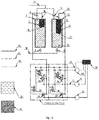
- Numbers in the drawings indicate the following items: 1 - first part of housing; 2 - bellows; 3 - suction valve; 4 - discharge valve; 5 -force pump; 6 - draw-off pump; 7 - discharge pressure control hydraulic distributor; 8 - hydraulic distributor; 9 - pilot-operated valve; 10 - tank with a working fluid; 11 - second part of housing; 12 - second bellows; 13 - suction valve; 14 - discharge valve; 15 - plug of the first bellows; 16 - hydraulic control system of pumping assembly; 17 - discharge line; 18 - suction line; 19 - pilot-operated valve; 20 - first hydraulic line; 21 - second hydraulic line; 22 - transducer of lower position; 23 - rod; 24 - tube; 25 - pumped fluid; 26 - working fluid; 27 - plug of the second bellows; 28 - rod; 29 - limit switch; 30 - limit switch; 31 - transducer of upper position; 32 - valve; 33 - valve;
- letters "a” and “b” indicate positions of hydraulic distributor for the force line control (7) while letters “c” and “d” show similar positions of hydraulic distributor (8).
- Pumping assembly ( Fig. 1 ) comprises a housing consisting of at least two parts (1) and (11), each part (1) and (11) of the pumping assembly housing having a cylindrical internal chamber.
- Bellows (2) and (12) are installed inside each of said housing parts (1) and (11) of the pumping assembly housing. These bellows (2) and (12) are mounted on inner upper or lower end surface of each housing part (1) and (11) of the pumping assembly housing, respectively.
- Each bellows (2) and (12) is closed in its free end with a plug (15) or (27), respectively.
- the chamber, formed by bellows (2) or (12), mounted on end surface of housing part (1) or (11) of the pumping assembly housing, and its plug (15) or (27), closing free end of bellows (2) or (12), respectively, is referred as the inner chamber of bellows (2) or (12).
- Bellows (2) and (12) with plugs installed inside parts (1) and (11) of the pumping assembly housing separate the working fluid (26) occurring in inner chambers of bellows (2) and (12) from the pumped fluid (25) occurring outside the bellows (2) and (12) in the same chambers of parts (1) and (11) of the pumping assembly housing.
- Each part (1) or (11) of the pumping assembly housing has inlet or outlet port suitable to connect the suction line (18) or discharge line (17), respectively.
- a discharge valve (4) or (14) is installed on the discharge line (17) of the pumped fluid (25).
- a suction valve (3) or (13) is installed on the suction line (18) of the pumped fluid.
- the pumping assembly further comprises a pumping assembly hydraulic control system (16), in turn comprising a tank (10) containing the working fluid; a force pump (5); two or more independent hydraulic lines (20) and (21), and a valve system.
- a pumping assembly hydraulic control system (16) in turn comprising a tank (10) containing the working fluid; a force pump (5); two or more independent hydraulic lines (20) and (21), and a valve system.
- the pumping assembly operation hydraulic control system (16) consists of two independent hydraulic lines (20) and (21).
- the first hydraulic line (20) is under pressure higher than the pumped fluid (25) inlet pressure in the suction line (18).
- the second hydraulic line (21) is under pressure lower than the pumped fluid (25) inlet pressure in the suction line (18).
- the first hydraulic line (20) of the pumping assembly control line (16) connects each bellows (2) and (12) with discharge pump (5) to supply the working fluid (26), the discharge pump being a component of the pumping assembly.
- the connection of each bellows (2) and (12) with discharge pump (5) is governed by a discharge pressure control hydraulic distributor (7) installed on the first hydraulic line (20).
- the discharge pressure control hydraulic distributor (7) is designed to distribute supplied working fluid (26) among said bellows (2) and (12).
- the first hydraulic line (20) of the pumping assembly control line (16) also connects the pump (5) designed for supplying the working fluid (26) with the tank (10) containing the working fluid.
- the first hydraulic line (20) connects the pump (5), designed for supplying the working fluid (26) to each bellows (2) and (12), with the hydraulic distributor (8) designed to unlock or lock the pilot-operated valve (9) or (19).
- the pilot-operated valves (9) and (19) are installed at junctions of respectively first and second hydraulic lines (20) and (21) of the control line (16).
- the second hydraulic line (21) of the control line (16) connects each bellows (2) and (12) with draw-off pump (6) designed to pump off the working fluid (26), the draw-off pump being a component of the pumping assembly.
- the second hydraulic line (21) also connects the pump (6), designed to pump off the working fluid (26), with the tank (10) containing the working fluid.
- Operating cycle of whole pumping assembly ( Fig. 1 ) may be divided into two stages depending on position (c) or (d) of the discharge pressure control hydraulic distributor (7).
- the pumping assembly When the discharge pressure control hydraulic distributor (7) is in its initial position (c), the pumping assembly operates as follows: Pumped fluid (25) enters the suction line (18). The discharge pressure control hydraulic distributor (7) switches to position (c) and simultaneously hydraulic distributor (8) switches to position (b), thereby causing opening of pilot-operated valve (19) and closing of pilot-operated valve (9). The force pump (5) and draw-off pump (6) ensure circulation of working fluid (26) in the control line (16) of the pumping assembly.
- draw-off pump (6) begins to draw off working fluid (26) from inner chamber of the second plugged bellows (12) into tank (10), while the force pump (5) begins to supply the working fluid into inner chamber of plugged bellows (12) from the tank (10).
- Removal of working fluid (26) from inner chamber of the second bellows (12) closed with a plug (27) in its free end creates underpressure in pumped fluid inside the second housing part (11), thereby opening suction valve (13) and closing the discharge valve (14) on the pumped fluid line. This underpressure causes filling of second housing part (11) with the pumped fluid (25).
- the pumping assembly When the discharge pressure control hydraulic distributor (7) is in its initial position (d), the pumping assembly operates as follows: The discharge pressure control hydraulic distributor (7) switches to position (d) and simultaneously hydraulic distributor (8) switches to position (a) thereby causing opening of pilot-operated valve (9) and closing of pilot-operated valve (19). The force pump (5) and draw-off pump (6) ensure circulation of working fluid in the control line of the pumping assembly.
- draw-off pump (6) begins to draw off working fluid from inner chamber of the first bellows (2) with the plug (15) into tank (10), while the force pump (5) begins to supply working fluid into inner chamber of bellows (12) with the plug (27) from the tank (10).
- Removal of working fluid from inner chamber of the first bellows (2) closed with a plug (15) in its free end creates underpressure in pumped fluid inside the first housing part (1), thereby opening suction valve (3) and closing the discharge valve (4). This underpressure causes filling of first housing part (1) with the pumped fluid (25).
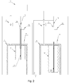
- One embodiment of the claimed invention provides determining positions of bellows (2) and (12) with the aid of position transducers (22), (31) and rod (23) ( Figure 2 ), the rod (23) moving in tube (24) with two installed position transducers (22), (31) at a distance of bellows stroke.
- the rod (23) is installed in the inner chamber of each bellows (2) and (12) closed in its end part with a plug (15) or (27), respectively.
- the rod (23) has holes drilled in its body.
- One end of rod (23) is attached to the plug (15) or (27), while the other end is loosely inserted in the tube (24).
- Tubes (24) are fixed in each housing part (1) and (11), respectively.
- Rod position transducers (22) and (31) are installed on each tube (24) perpendicularly to its axis. Upper position transducers (22) are located in the upper part of each tube (24), whereas the lower position transducers (31) are located in the lower part of each tube (24). The distance between upper position transducers (22) and lower position transducers (31) must be equal or less than stroke of bellows (2) or (12) closed with plug (15) or (27), respectively.
- upper position transducer (31) transmits signal "bellows is extended", which switches discharge pressure control hydraulic distributor (7) and hydraulic distributor (8). Thereafter the rod (23) starts to move up.
- the upper position transducer (22) transmits signal "bellows is compressed", which switches discharge pressure control hydraulic distributor (7) and hydraulic distributor (8) again.
- Another embodiment of the claimed invention provides determining position of bellows with the aid of a single position transducer in combination with the rod (23), wherein the rod has two holes for position control.
- alternate values "bellows is extended” and “bellows is compressed” are assigned to signals generated by the transducer when a hole in the rod (23) aligns with the transducer's working surface.
- FIG. 3 Yet another embodiment of the claimed invention with bellows position control using limit switches (29) and (30) ( Figure 3 ) provides determining positions of bellows (2) and (12) closed with plugs (15) or (27) in their free ends, respectively, based on touching limit switches by the plugs.
- lower limit switches (30) are installed in lower end of each housing part (1) and (11) while upper limit switches (29) are installed in upper end of each bellows (2) and (12).
- the switch transmits signal "bellows is extended", which switches discharge pressure control hydraulic distributor (7) and hydraulic distributor (8). Thereafter the plugged bellows (2) or (12) starts to move up.
- Still another embodiment of the claimed invention provides determining positions of bellows with the aid of a cable wound on a spool (48) and (49).
- Spools (48) and (49) are installed in the upper parts of the pumping assembly housing parts (1) and (11), and ends of cables are fixed on plugs (15) and (27), respectively.
- the reciprocating movement of bellows (2) and (12) leads to unwinding and subsequent winding the cable onto each spool (48) and (49).
- rotational movement of spools (48) and (49) caused by displacements of bellows is detected by transducers (46) and (47).
- Transducers (46) and (47) may be of either contact or contactless type.
- bellows position can be determined ( Fig. 9 ) using the controlled filling of inner chambers of bellows (2) or (12) closed in their end parts with plugs (15) or (27), respectively, with a working fluid (26) supplied by a force pump (5).
- a rotation speed sensor (50) is mounted on the force pump (5) and used to calculate the working fluid volume required to fill the inner chamber of bellows (2) or (12) closed in its end part with plug (15) or (27), respectively.
- the pumping assembly may comprise more than two parts of housing. Accordingly, increase in number of housing parts causes the necessity to install a number of additional components per each additional part, namely:
- a pumping assembly ( Fig. 4 ) that comprises a housing divided into four parts, each part having a cylindrical internal chamber. Bellows are installed inside each of said housing parts of the pumping assembly housing. Each of these bellows is attached to upper end inner surface of each housing part of the pumping assembly. Each bellows is closed with a plug at the bottom.
- the chamber formed by bellows mounted on upper end surface of housing part of the pumping assembly housing and its plug is referred as the inner chamber of bellows.
- Bellows with plugs installed inside parts of the pumping assembly housing separate the working fluid (26) occurring in inner chambers of bellows from the pumped fluid (25) occurring outside the bellows in the same chambers of parts of the pumping assembly housing.
- Each part of the pumping assembly housing has inlet or outlet port suitable to connect the suction line (18) or discharge line (19), respectively.
- Discharge valves are installed on the discharge line (17) of the pumped fluid (25).
- Suction valves are installed on the suction line (18) of the pumped fluid.
- the pumping assembly operation control line (16) consists of two independent hydraulic lines (20) and (21).
- the first hydraulic line (20) is under pressure higher than the pumped fluid (25) inlet pressure in the suction line (18).
- the second hydraulic line (21) is under pressure lower than the pumped fluid (25) inlet pressure in the suction line (18).
- the first hydraulic line (20) of the pumping assembly control line (16) connects each bellows with discharge pump (5) to supply the working fluid (26), the discharge pump being a component of the pumping assembly.
- the connection of each bellows pair with discharge pump (5) is governed by a discharge pressure control hydraulic distributor installed on the first hydraulic line (20).
- the discharge pressure control hydraulic distributor is designed to distribute supplied working fluid (26) among said bellows.
- the first hydraulic line (20) of the pumping assembly control line (16) also connects the pump (5) designed for supplying the working fluid (26) with the tank (10) containing the working fluid.
- the first hydraulic line (20) connects the pump (5), designed to supply the working fluid (26) to each bellows pair, with the hydraulic distributor designed to unlock or lock the pilot-operated valves.
- One pilot-operated valve is installed on the second hydraulic line (21) of the control line (16).
- the second hydraulic line (21) of the control line (16) connects each bellows with draw-off pump (6) designed to pump off the working fluid (26), the draw-off pump being a component of the pumping assembly.
- the second hydraulic line (21) also connects the draw-off pump (6), designed to pump off the working fluid (26), with the tank (10) containing the working fluid.
- valves can have electromagnetic, hydraulic, or pneumatic control.
- working fluid control in the pumping assembly begins from the discharge pressure control hydraulic distributor (7).
- the discharge pressure control hydraulic distributor (7) is switched to position (c)
- working fluid is forced into inner chamber of the first bellows (2) closed with the plug (15) in its free end part and simultaneously drawn off from inner chamber of bellows (12) closed with the plug (27) in its free end part.
- the discharge pressure control hydraulic distributor (7) is switched to position (d), and working fluid is forced into inner chamber of the second bellows (12) closed with the plug (27) in its free end part and simultaneously drawn off from inner chamber of bellows (2) closed with the plug (15) in its free end part.
- FIG. 6 Another embodiment of flow control system shown in Fig. 6 provides working fluid control using a system of valves (32), (33), (34), (35), and hydraulic distributors (36), (37), (38), (39) acting via a control line (41).
- the working fluid control system is driven by a control pump (40) through the control line (41), valve system (32), (33), (34), (35), and hydraulic distributors (36), (37), (38), (39).
- FIG. 7 Yet another embodiment of flow control system shown in Fig. 7 provides working fluid control using a system of hydraulic locks (42), (43), (44), (45) with electromagnetic control.
- Operating cycle of pumping assembly with a system of electromagnetically controlled hydraulic locks (42), (43), (44), (45) may be divided depending on position of these hydraulic locks (open) or (closed).
- the force pump (5) supplies the working fluid to internal chamber of the first bellows (2) closed with a plug (15) in its free end.
- An overpressure arises inside the first housing part (1), thereby closing suction valve (3) and opening the discharge valve (4).
- the working fluid is injected into internal chamber of the second bellows (2) closed with a plug (27) in its free end, the pumped fluid (25) is forced out into discharge line (17).
- draw-off pump (6) begins to draw off working fluid from inner chamber of the second bellows (12) closed with plug (27) in its free end part.
Landscapes
- Engineering & Computer Science (AREA)
- Mechanical Engineering (AREA)
- General Engineering & Computer Science (AREA)
- Reciprocating Pumps (AREA)
- Eye Examination Apparatus (AREA)
Applications Claiming Priority (2)
| Application Number | Priority Date | Filing Date | Title |
|---|---|---|---|
| RU2018134507A RU2685353C1 (ru) | 2018-10-02 | 2018-10-02 | Насосная установка |
| PCT/RU2019/000700 WO2020071958A1 (ru) | 2018-10-02 | 2019-10-02 | Насосная установка |
Publications (2)
| Publication Number | Publication Date |
|---|---|
| EP3862565A1 true EP3862565A1 (de) | 2021-08-11 |
| EP3862565A4 EP3862565A4 (de) | 2022-05-18 |
Family
ID=66168228
Family Applications (1)
| Application Number | Title | Priority Date | Filing Date |
|---|---|---|---|
| EP19868378.1A Pending EP3862565A4 (de) | 2018-10-02 | 2019-10-02 | Pumpenanordnung |
Country Status (8)
| Country | Link |
|---|---|
| US (1) | US11384749B2 (de) |
| EP (1) | EP3862565A4 (de) |
| CN (1) | CN112823244B (de) |
| AU (1) | AU2019352546B2 (de) |
| EA (1) | EA202190932A1 (de) |
| RU (1) | RU2685353C1 (de) |
| WO (1) | WO2020071958A1 (de) |
| ZA (1) | ZA202102706B (de) |
Families Citing this family (2)
| Publication number | Priority date | Publication date | Assignee | Title |
|---|---|---|---|---|
| DE102021002178A1 (de) * | 2021-04-24 | 2022-10-27 | Hydac Technology Gmbh | Fördereinrichtung |
| DE102021003639A1 (de) * | 2021-07-14 | 2023-01-19 | Hydac Technology Gmbh | Fördereinrichtung |
Family Cites Families (29)
| Publication number | Priority date | Publication date | Assignee | Title |
|---|---|---|---|---|
| FR1328970A (fr) * | 1962-04-21 | 1963-06-07 | Commissariat Energie Atomique | Pompe doseuse |
| US3524714A (en) * | 1968-10-30 | 1970-08-18 | Us Air Force | Pneumatic bellows pump |
| SU667685A1 (ru) * | 1976-10-20 | 1979-06-15 | Govberg Artem S | Гидроприводна диафрагменна насосна установка |
| SU1278487A1 (ru) * | 1984-04-16 | 1986-12-23 | Предприятие П/Я М-5356 | Гидроприводной насосный агрегат |
| GB2185291A (en) * | 1986-01-23 | 1987-07-15 | Astrakhanskoe N Proizv Ob Okra | Pump unit of an apparatus for applying coatings |
| JPS63106379A (ja) * | 1986-10-23 | 1988-05-11 | Sunstar Giken Kk | 流体圧送用ポンプシステム |
| DE58902307D1 (de) * | 1988-10-06 | 1992-10-22 | Hans Willi Meinz | Doppeltwirkende faltenbalgpumpe. |
| SU1671962A1 (ru) * | 1989-04-27 | 1991-08-23 | Специальное проектно-конструкторское и технологическое бюро по погружному электрооборудованию для бурения скважин и добычи нефти Всесоюзного научно-производственного объединения "Потенциал" | Диафрагменна насосна установка |
| US5228473A (en) * | 1990-10-09 | 1993-07-20 | Montana Sulphur & Chemical Co. | Internal safety valve system |
| US5220943A (en) * | 1990-10-09 | 1993-06-22 | Montana Sulphur & Chemical Co. | Internal pump assembly |
| US5249745A (en) * | 1991-09-19 | 1993-10-05 | Giacomo Bertolotti | Fluid distribution system |
| US5308230A (en) * | 1993-03-08 | 1994-05-03 | Stainless Steel Products, Inc. | Bellows pump |
| JP4078044B2 (ja) | 2001-06-26 | 2008-04-23 | 日本パーカライジング株式会社 | 金属表面処理剤、金属材料の表面処理方法及び表面処理金属材料 |
| US6575712B1 (en) * | 2001-09-28 | 2003-06-10 | Slavcho Slavchev | Air compressor system |
| AU2002950421A0 (en) * | 2002-07-29 | 2002-09-12 | Combined Resource Engineering Pty Ltd | Fluid operating pump |
| EP1602830A1 (de) * | 2004-06-02 | 2005-12-07 | Ailand Corporation S.A. | Hydraulisch angetriebene mehrzylindrige Kolbenpumpe |
| DE102004031673B4 (de) * | 2004-06-30 | 2009-04-16 | Erbe Elektromedizin Gmbh | Medizinische Pumpe |
| US7607750B2 (en) * | 2004-09-27 | 2009-10-27 | Seiko Epson Corporation | Pump control mechanism, printer incorporating the same, and pump control method |
| CN101193815B (zh) * | 2005-03-04 | 2012-03-28 | 液化空气电子美国有限公司 | 容积流体输送系统中的流体状态的控制 |
| JP4694377B2 (ja) * | 2006-01-27 | 2011-06-08 | シーケーディ株式会社 | 薬液供給システム |
| US7444798B2 (en) | 2006-07-26 | 2008-11-04 | Macdon Industries Ltd. | Crop feed arrangement for the header of a combine harvester |
| GB0707220D0 (en) * | 2007-04-14 | 2007-05-23 | Stratabolt Pty Ltd | Improved pump |
| JP5345152B2 (ja) * | 2007-12-20 | 2013-11-20 | ボルボ テクノロジー コーポレイション | 燃料ポンプシステム、燃料ポンプシステムの動作方法及び燃料ポンプシステムを含む燃料噴射システム |
| JP5188385B2 (ja) * | 2008-12-26 | 2013-04-24 | 株式会社日立ハイテクノロジーズ | プラズマ処理装置及びプラズマ処理装置の運転方法 |
| US20100178182A1 (en) * | 2009-01-09 | 2010-07-15 | Simmons Tom M | Helical bellows, pump including same and method of bellows fabrication |
| US20140319181A1 (en) * | 2013-04-30 | 2014-10-30 | E I Du Pont De Nemours And Company | Dispensing vessel having a corrugated secondary container for use in a printing apparatus for depositing a liquid composition on a backplane |
| EP2913525A1 (de) * | 2014-02-26 | 2015-09-02 | Garniman SA | Hydraulisch angetriebene Balgpumpe |
| US20170045044A1 (en) * | 2015-08-11 | 2017-02-16 | Hydril Usa Distribution, Llc | Pump chamber position indicator |
| NO20171099A1 (en) * | 2017-07-04 | 2019-01-07 | Rsm Imagineering As | Pressure transfer device and associated system, fleet and use, for pumping high volumes of fluids with particles at high pressures |
-
2018
- 2018-10-02 RU RU2018134507A patent/RU2685353C1/ru active
-
2019
- 2019-10-02 US US16/760,453 patent/US11384749B2/en active Active
- 2019-10-02 EP EP19868378.1A patent/EP3862565A4/de active Pending
- 2019-10-02 EA EA202190932A patent/EA202190932A1/ru unknown
- 2019-10-02 CN CN201980065733.4A patent/CN112823244B/zh active Active
- 2019-10-02 AU AU2019352546A patent/AU2019352546B2/en active Active
- 2019-10-02 WO PCT/RU2019/000700 patent/WO2020071958A1/ru not_active Ceased
-
2021
- 2021-04-22 ZA ZA2021/02706A patent/ZA202102706B/en unknown
Also Published As
| Publication number | Publication date |
|---|---|
| RU2685353C1 (ru) | 2019-04-18 |
| WO2020071958A1 (ru) | 2020-04-09 |
| ZA202102706B (en) | 2022-08-31 |
| CA3114343A1 (en) | 2020-04-09 |
| AU2019352546B2 (en) | 2023-07-13 |
| US20200340470A1 (en) | 2020-10-29 |
| BR112021006217A2 (pt) | 2021-07-06 |
| EP3862565A4 (de) | 2022-05-18 |
| AU2019352546A1 (en) | 2021-05-27 |
| CN112823244A (zh) | 2021-05-18 |
| EA202190932A1 (ru) | 2021-07-06 |
| CN112823244B (zh) | 2022-11-01 |
| US11384749B2 (en) | 2022-07-12 |
Similar Documents
| Publication | Publication Date | Title |
|---|---|---|
| CA2940124C (en) | Hydraulically driven bellows pump | |
| CA3042551C (en) | Method and system for intensifying slurry pressure | |
| CN1973130B (zh) | 液压驱动多缸隔膜泵送机以及其泵缸和操作该泵送机的方法 | |
| US7540230B2 (en) | Three-way poppet valve for work exchanger | |
| US11384749B2 (en) | Pump assembly | |
| CA3114343C (en) | Pump assembly | |
| US4397614A (en) | Unbalanced spool | |
| CN214460795U (zh) | 一种可数字化液压智控系统及挖掘机 | |
| WO2000070221A1 (fr) | Pompe de compression hydraulique | |
| CN208456793U (zh) | 往复式增压泵 | |
| EA040904B1 (ru) | Насосная установка | |
| CN109779871B (zh) | 一种液力注入装置及其用途 | |
| BR112021006217B1 (pt) | Conjunto de bombeamento | |
| RU2628840C1 (ru) | Гидроприводной погружной насосный агрегат | |
| CN110985456B (zh) | 气液组合旋转运动结构 | |
| SU1035281A1 (ru) | Групповой гидропривод штанговых глубинных насосов | |
| KR100955331B1 (ko) | 유체작동 펌프 및 이 펌프를 구비하는 펌핑시스템 | |
| JPH0275780A (ja) | 摩耗性又は侵食性スラリー用ポンプ装置 | |
| KR970026895A (ko) | 고농도 유체 압송장치 | |
| IL172032A (en) | Three-way poppet valve for work exchanger | |
| CN105697441A (zh) | 液压行程自动换向阀及旋泵成孔桩机液压控制系统 |
Legal Events
| Date | Code | Title | Description |
|---|---|---|---|
| STAA | Information on the status of an ep patent application or granted ep patent |
Free format text: STATUS: THE INTERNATIONAL PUBLICATION HAS BEEN MADE |
|
| PUAI | Public reference made under article 153(3) epc to a published international application that has entered the european phase |
Free format text: ORIGINAL CODE: 0009012 |
|
| STAA | Information on the status of an ep patent application or granted ep patent |
Free format text: STATUS: REQUEST FOR EXAMINATION WAS MADE |
|
| 17P | Request for examination filed |
Effective date: 20210426 |
|
| AK | Designated contracting states |
Kind code of ref document: A1 Designated state(s): AL AT BE BG CH CY CZ DE DK EE ES FI FR GB GR HR HU IE IS IT LI LT LU LV MC MK MT NL NO PL PT RO RS SE SI SK SM TR |
|
| DAV | Request for validation of the european patent (deleted) | ||
| DAX | Request for extension of the european patent (deleted) | ||
| A4 | Supplementary search report drawn up and despatched |
Effective date: 20220419 |
|
| RIC1 | Information provided on ipc code assigned before grant |
Ipc: F04B 49/00 20060101ALI20220411BHEP Ipc: F04B 43/00 20060101ALI20220411BHEP Ipc: F04B 43/113 20060101AFI20220411BHEP |
|
| STAA | Information on the status of an ep patent application or granted ep patent |
Free format text: STATUS: EXAMINATION IS IN PROGRESS |
|
| 17Q | First examination report despatched |
Effective date: 20231019 |
|
| GRAP | Despatch of communication of intention to grant a patent |
Free format text: ORIGINAL CODE: EPIDOSNIGR1 |
|
| STAA | Information on the status of an ep patent application or granted ep patent |
Free format text: STATUS: GRANT OF PATENT IS INTENDED |
|
| INTG | Intention to grant announced |
Effective date: 20251126 |