EP3864741B1 - Moteur électrique, système de freinage et véhicule - Google Patents
Moteur électrique, système de freinage et véhicule Download PDFInfo
- Publication number
- EP3864741B1 EP3864741B1 EP19789620.2A EP19789620A EP3864741B1 EP 3864741 B1 EP3864741 B1 EP 3864741B1 EP 19789620 A EP19789620 A EP 19789620A EP 3864741 B1 EP3864741 B1 EP 3864741B1
- Authority
- EP
- European Patent Office
- Prior art keywords
- stator
- electric drive
- housing
- housing insert
- coil
- Prior art date
- Legal status (The legal status is an assumption and is not a legal conclusion. Google has not performed a legal analysis and makes no representation as to the accuracy of the status listed.)
- Active
Links
Images


Classifications
-
- F—MECHANICAL ENGINEERING; LIGHTING; HEATING; WEAPONS; BLASTING
- F16—ENGINEERING ELEMENTS AND UNITS; GENERAL MEASURES FOR PRODUCING AND MAINTAINING EFFECTIVE FUNCTIONING OF MACHINES OR INSTALLATIONS; THERMAL INSULATION IN GENERAL
- F16D—COUPLINGS FOR TRANSMITTING ROTATION; CLUTCHES; BRAKES
- F16D65/00—Parts or details
- F16D65/14—Actuating mechanisms for brakes; Means for initiating operation at a predetermined position
- F16D65/28—Actuating mechanisms for brakes; Means for initiating operation at a predetermined position arranged apart from the brake
-
- H—ELECTRICITY
- H02—GENERATION; CONVERSION OR DISTRIBUTION OF ELECTRIC POWER
- H02K—DYNAMO-ELECTRIC MACHINES
- H02K1/00—Details of the magnetic circuit
- H02K1/06—Details of the magnetic circuit characterised by the shape, form or construction
- H02K1/22—Rotating parts of the magnetic circuit
- H02K1/27—Rotor cores with permanent magnets
- H02K1/2706—Inner rotors
- H02K1/272—Inner rotors the magnetisation axis of the magnets being perpendicular to the rotor axis
- H02K1/274—Inner rotors the magnetisation axis of the magnets being perpendicular to the rotor axis the rotor consisting of two or more circumferentially positioned magnets
- H02K1/2753—Inner rotors the magnetisation axis of the magnets being perpendicular to the rotor axis the rotor consisting of two or more circumferentially positioned magnets the rotor consisting of magnets or groups of magnets arranged with alternating polarity
- H02K1/278—Surface mounted magnets; Inset magnets
-
- H—ELECTRICITY
- H02—GENERATION; CONVERSION OR DISTRIBUTION OF ELECTRIC POWER
- H02K—DYNAMO-ELECTRIC MACHINES
- H02K15/00—Processes or apparatus specially adapted for manufacturing, assembling, maintaining or repairing of dynamo-electric machines
- H02K15/08—Forming windings by laying conductors into or around core parts
- H02K15/095—Forming windings by laying conductors into or around core parts by laying conductors around salient poles
-
- H—ELECTRICITY
- H02—GENERATION; CONVERSION OR DISTRIBUTION OF ELECTRIC POWER
- H02K—DYNAMO-ELECTRIC MACHINES
- H02K21/00—Synchronous motors having permanent magnets; Synchronous generators having permanent magnets
- H02K21/12—Synchronous motors having permanent magnets; Synchronous generators having permanent magnets with stationary armatures and rotating magnets
- H02K21/14—Synchronous motors having permanent magnets; Synchronous generators having permanent magnets with stationary armatures and rotating magnets with magnets rotating within the armatures
- H02K21/16—Synchronous motors having permanent magnets; Synchronous generators having permanent magnets with stationary armatures and rotating magnets with magnets rotating within the armatures having annular armature cores with salient poles
-
- H—ELECTRICITY
- H02—GENERATION; CONVERSION OR DISTRIBUTION OF ELECTRIC POWER
- H02K—DYNAMO-ELECTRIC MACHINES
- H02K3/00—Details of windings
- H02K3/46—Fastening of windings on the stator or rotor structure
- H02K3/52—Fastening salient pole windings or connections thereto
- H02K3/521—Fastening salient pole windings or connections thereto applicable to stators only
- H02K3/522—Fastening salient pole windings or connections thereto applicable to stators only for generally annular cores with salient poles
-
- B—PERFORMING OPERATIONS; TRANSPORTING
- B60—VEHICLES IN GENERAL
- B60T—VEHICLE BRAKE CONTROL SYSTEMS OR PARTS THEREOF; BRAKE CONTROL SYSTEMS OR PARTS THEREOF, IN GENERAL; ARRANGEMENT OF BRAKING ELEMENTS ON VEHICLES IN GENERAL; PORTABLE DEVICES FOR PREVENTING UNWANTED MOVEMENT OF VEHICLES; VEHICLE MODIFICATIONS TO FACILITATE COOLING OF BRAKES
- B60T13/00—Transmitting braking action from initiating means to ultimate brake actuator with power assistance or drive; Brake systems incorporating such transmitting means, e.g. air-pressure brake systems
- B60T13/74—Transmitting braking action from initiating means to ultimate brake actuator with power assistance or drive; Brake systems incorporating such transmitting means, e.g. air-pressure brake systems with electrical assistance or drive
- B60T13/745—Transmitting braking action from initiating means to ultimate brake actuator with power assistance or drive; Brake systems incorporating such transmitting means, e.g. air-pressure brake systems with electrical assistance or drive acting on a hydraulic system, e.g. a master cylinder
-
- F—MECHANICAL ENGINEERING; LIGHTING; HEATING; WEAPONS; BLASTING
- F16—ENGINEERING ELEMENTS AND UNITS; GENERAL MEASURES FOR PRODUCING AND MAINTAINING EFFECTIVE FUNCTIONING OF MACHINES OR INSTALLATIONS; THERMAL INSULATION IN GENERAL
- F16D—COUPLINGS FOR TRANSMITTING ROTATION; CLUTCHES; BRAKES
- F16D2121/00—Type of actuator operation force
- F16D2121/02—Fluid pressure
- F16D2121/04—Fluid pressure acting on a piston-type actuator, e.g. for liquid pressure
-
- F—MECHANICAL ENGINEERING; LIGHTING; HEATING; WEAPONS; BLASTING
- F16—ENGINEERING ELEMENTS AND UNITS; GENERAL MEASURES FOR PRODUCING AND MAINTAINING EFFECTIVE FUNCTIONING OF MACHINES OR INSTALLATIONS; THERMAL INSULATION IN GENERAL
- F16D—COUPLINGS FOR TRANSMITTING ROTATION; CLUTCHES; BRAKES
- F16D2121/00—Type of actuator operation force
- F16D2121/18—Electric or magnetic
- F16D2121/24—Electric or magnetic using motors
-
- H—ELECTRICITY
- H02—GENERATION; CONVERSION OR DISTRIBUTION OF ELECTRIC POWER
- H02K—DYNAMO-ELECTRIC MACHINES
- H02K2203/00—Specific aspects not provided for in the other groups of this subclass relating to the windings
- H02K2203/09—Machines characterised by wiring elements other than wires, e.g. bus rings, for connecting the winding terminations
Definitions
- the present invention relates to an electric drive, a braking device with such an electric drive and a vehicle with such a braking device.
- the proposed electric drive is intended for use in an electro-hydraulic braking device, the electric drive driving a ball screw which as such displaces a piston of a cylinder-piston arrangement in order to generate a braking pressure.
- a vehicle is to be understood as meaning any type of vehicle that has to be supplied with a liquid and/or gaseous fuel in order to operate, but in particular passenger cars and/or commercial vehicles.
- the vehicle can also be a partially electric or fully electric vehicle, but in particular a passenger car and/or commercial vehicle.
- the DE 10 2017 205 532 A1 discloses a stator of an electrical machine, an electrical machine, and a method for producing such a machine, in particular for adjusting moving parts in a motor vehicle, with a pole housing, on the inner wall of which winding carriers bear electrical coils, the winding carriers having a stator tooth which is attached to a Yoke element is formed, which rests radially on the inner wall, and an insulation mask is arranged on the winding support, which insulates the electrical coil from the winding support, and the insulation mask extends axially beyond the yoke element with an axial extension, the axial extension having a running in the circumferential direction collar radially applied to the inner wall of the pole housing.
- the object of the present invention is to provide an electric drive for an electro-hydraulic braking device which is as compact as possible and which can also be manufactured and installed as simply as possible.
- the electric drive should be able to be produced as cost-effectively as possible.
- a coil carrier made of plastic be injection molded onto the individual stator teeth, forming a first front panel which faces the rotor in an installation position of the stator, and injection molding a second front panel which faces away from the rotor in the installation position. wherein the associated winding of wire belonging to the coil is sandwiched between the first panel and the second panel.
- a pin-like anchoring section - also known as anchoring dome - is formed on the individual coil carriers on the side of the respective second panel and is made of plastic and extends in a longitudinal direction of the electric drive through an associated opening in the housing insert to beyond an end face of the housing insert facing away from the stator-rotor unit extends and engages behind the end face in order to positively connect the housing insert to the stator.
- This plastic anchoring sections can be caulked with the housing insert.
- a caulking is to be understood as meaning the production of a non-positive and positive connection between the respective anchoring section and the housing insert, with the anchoring section being plastically deformed. There is therefore no need for an additional, separate element in order to fix the housing insert in relation to the stator. This allows a longitudinal extension of the electric drive to be minimized.
- the housing insert encloses a contact arrangement of at least two mutually spaced, electrically conductive contact elements for the electrical supply of at least two phases Coil of the stator, the contact elements being electrically insulated from one another by the plastic.
- the contact elements have first contact sections for external contacting of the stator with a plug and second contact sections for internal contacting of the stator with the respective contact elements. These first and second contact sections are also referred to as contact pins or contact lugs.
- the first contact sections and the second contact sections protrude in a longitudinal direction of the electric drive from the plastic of the housing insert from an end face of the housing insert facing away from the stator-rotor unit. This also allows the longitudinal extent of the electric drive to be minimized.
- the contact arrangement has three mutually spaced, electrically conductive contact elements for the electrical supply of three phases of the coil.
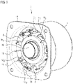
- the proposed electric drive 2 is intended for use in an electro-hydraulic braking device.
- the electric drive 2 is designed as an electronically commutated, three-phase (phases U, V, W) DC motor in the form of an internal rotor.
- the electric drive 2 includes a housing 4 which is formed, for example, from deep-drawn sheet metal and which can be attached to a housing of the electro-hydraulic braking device via a flange 6 .
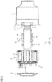
- a stator-rotor unit 18, 26 is installed, which a - ball screw for moving a piston - not shown here drives a cylinder-piston arrangement to generate a braking pressure.
- the electric drive proposed within the scope of this description of the figures can also be operated as an electronically commutated AC motor.
- “separately” means that the housing insert 8 is not part of the stator 18 .
- the housing insert 8 encloses a contact arrangement 22 of three electrically conductive contact elements KE U , KE V , KE W (cf. 2 in conjunction with 10 ), which are electrically insulated from one another by the plastic of the housing insert 8 .
- Each of the contact elements KE U , KE V , KE W has a part-circular base section BA, on which a single, first contact section U I , V I , W I and a total of four second contact sections U II , V II , W II are formed ( see. 10 ).
- Both the first contact sections U I , V I , W I and the second contact sections U II , V II , W II protrude from an end face of the housing insert 8 facing away from the stator-rotor unit 18 , 26 .
- individual wire ends D A , D E of a coil 20 of a stator 18 are routed outwards through the housing insert 8 through associated openings in the housing insert 8, so that these wire ends also protrude from said end face.
- the coil 20 is formed by a total of 6 wire windings.
- These wire ends are contacted with the respectively associated second contact sections U II , V II , W II .
- the wire ends can be integrally connected to the respective contact sections U II , V II , W II by resistance welding (cf. connection 14 in 1 or 6 ).
- the first contact sections U I , V I , W I are used for external contacting of the stator 18 with a plug.
- the second contact sections U II , V II , W II are used for internal contacting of the stator 18 with the three contact elements KE 1 , KE 2 , KE 3 (cf. 2 in conjunction with 10 ), each of which is assigned to one of three phases U, V, W of the coil 20.
- the contact sections U II , V II , W II are assigned in pairs to a coil section, ie a start of a wire winding DW U and an end of a wire winding DW V , DW W adjacent thereto, with the coil section being one of the phases U, V, W of the coil 20 belongs.
- the opposing pairs of contact sections U II , V II , W II each make contact with a coil section belonging to the same phase U, V or W (cf. 10 ).
- the division of the contact elements KE U , KE V , KE W can be such that the spacing between the associated contact sections U II , V II , W II is different (cf. 10 ). In principle, however, this spacing can also be identical if the wire ends D A , DE of the coil 20 are routed away accordingly.
- the 2 and 7 in connection with the 10 illustrate that two adjacent of the total of four second contact sections U II , V II , W II provided per contact element KE U , KE V , KE W , which are formed as such via an associated web section SA on the base section BA, have a wire start D A one connect the wire windings DW U , DW V , DW W to a wire end D E of a wire winding DW U , DW V , DW W adjacent thereto.
- These two adjacent wire windings DW U , DW V , DW W belong to one of the three phases U, V, W (cf. 4 ).
- individual pin-like anchoring sections 16 made of plastic of the stator 18 protrude from said end face, which are formed on the stator 18 and are connected by associated Openings in the housing insert 8 extend through the housing insert 8.
- These plastic anchoring sections 16 are caulked with the housing insert 8 in a form-fitting manner, for example by so-called hot caulking.
- bulging areas which are spaced evenly apart from one another can be provided in the housing sheet metal, in each of which a bulging pointing radially inwards is formed.
- a fastening hole is also formed in the flange in order to be able to attach the housing 4 to the housing of the electro-hydraulic braking device.
- the stator 18 is clamped to the housing 4 .
- the permanently magnetized rotor 26 enclosed by the stator 18 comprises a tube 28 which is press-connected to a hub 30 .
- the hub 30 carries an arrangement of a plurality of permanent magnets 32 in the form of shell magnets which as such interact with the coil 20 .
- the tube 28 is also laser-welded at one of its two ends to a bearing bushing 36 which as such extends through an angular contact ball bearing 34 acting as a "fixed bearing” via which the tube 28 is accommodated in the region of one end of the housing 4 .
- the tube 28 is also accommodated by a ball bearing 38 which acts as a "loose bearing” and which is accommodated by the housing insert 8 in a centering manner.
- the housing insert 8 presses against the ball bearing 38 or its outer ring via an annular spring element 24, for example, in the form of a corrugated spring, which is enclosed by the housing insert 8 as such.
- the spring element 24 can be cohesively connected to the housing insert 8 in that it is correspondingly encapsulated during the plastic encapsulation of the housing insert 8 .
- the housing insert 8 covers the stator-rotor unit 18, 26 in the sense of a shield or housing and bearing shield.
- the proposed housing insert 8 also reduces the length tolerances to be taken into account in the longitudinal direction X-X of the electric drive 2 (reduction of a chain of length tolerances).
- the integration of the contact arrangement 22 in the housing insert 8 causes a very compact or very dense arrangement of the coil 20 forming individual wire windings DW U , DW V , DW W in the housing 4 (compact or dense "packaging"), because a a section--for example an end section of the stator 18--enclosing plastic overmoulding, which as such encompasses the said contact arrangement, is omitted.
- the stator 18 clamped in the housing 4 comprises, for example, an annular arrangement of a total of twelve magnetizable stator teeth SZ 1 , SZ 2 . . . SZ 11 , SZ 12 forming poles.
- These stator teeth SZ 1 , SZ 2 ... SZ 11 , SZ 12 are divided into separate pairs of teeth SZ 1 & SZ 2 , SZ 3 & SZ 4 ... SZ 11 & SZ 12 , with each of the pairs of teeth SZ 1 & SZ 2 , SZ 3 & SZ 4 ... SZ 11 & SZ 12 is wound with its own common metal wire forming part of the coil 20 (cf. 3 and 4 ).
- the two wire ends D A , D E of the respective pairs of teeth ( 3 ) are electrically contacted with the housing insert 8 described above.
- the individual stator teeth SZ 1 , SZ 2 are held together by means of an embossing, which is produced as such by means of a stamping die in a longitudinal extent X-X of the laminated core.
- the embossing extends over the entire longitudinal extent X-X of the respective laminated core, so that a positive connection is created between the individual laminated layers, which holds the laminated layers together.
- first panel P i inside
- second panel P a outside
- first front panel P i faces the rotor 26 in an installed position of the stator 18
- second front panel P a faces away from the rotor 26 in the installed position of the stator 18 . Therefore, the first panel P i can also be referred to as the inner panel and the second panel P a can also be referred to as the outer.
- the wire winding DW U , DW V , DW W associated with the respective stator tooth and belonging to the coil 20 is enclosed between the panel P i and the panel P a .
- the coil carrier can be sprayed in such a way that it either completely or only partially encloses the respective stator tooth (cf. e.g 3 ).
- the 3 illustrates an arrangement of two stator teeth SZ 1 , SZ 2 forming a tooth pair, which are arranged opposite one another for common wrapping with a metal wire in such a way that initially the outer ends of the tooth pair in the position of use—or the second end faces—are opposite one another.
- a pin-like anchoring section 16 - also known as the anchoring dome - is molded around with the coil carrier panel P a represents (cf. 7 and 8 ).
- this anchoring section 16 extends through an associated opening in the housing insert 8 to an end face of the housing insert 8 facing away from the stator-rotor unit 18, 26, which the anchoring section 16 engages behind for the purpose of a form fit.
- the individual wire ends D A , DE of the pairs of teeth SZ 1 & SZ 2 , SZ 3 & SZ 4 ... SZ 11 & SZ 12 are in the longitudinal direction X - X of the electric drive 2 through associated openings in the housing insert 8 to above said out of the end face of the housing insert 8 facing away from the stator-rotor unit 18, 26 and electrically contacted with the housing insert 8 via respectively assigned contact sections U II , V II , W II .
- the contact is such that each one Start of wire D A of one of the wire windings DW U , DW V , DW W with a wire end DE of an adjacent wire winding DW U , DW V , DW W by means of the contact arrangement 22 enclosed by the housing insert 8, namely via one of the said contact elements KE U , KE V , KE W is connected.
- These respectively adjacent and interconnected wire windings DW U , DW V , DW W belong to one of the three phases U, V, W.
- the proposed coil design also contributes to a very compact or very dense arrangement of the individual wire windings DW U , DW V , DW W forming the coil 20 (compact or dense “packaging”).
- the result is a very compact electric drive 2, which can also be easily manufactured and installed.
- the electric drive 2 can also be produced inexpensively.
Landscapes
- Engineering & Computer Science (AREA)
- Power Engineering (AREA)
- General Engineering & Computer Science (AREA)
- Mechanical Engineering (AREA)
- Transportation (AREA)
- Manufacturing & Machinery (AREA)
- Motor Or Generator Frames (AREA)
- Insulation, Fastening Of Motor, Generator Windings (AREA)
Claims (13)
- Entraînement électrique (2) destiné à être utilisé dans un dispositif de freinage électrohydraulique, ledit entraînement électrique comprenant :• un boîtier (4) et• une unité stator-rotor (18, 26) logée dans le boîtier (4) et destinée à déplacer un piston d'un ensemble cylindre-piston afin de générer une pression de freinage,l'unité stator-rotor (18, 26) comportant un stator (18) pourvu d'un ensemble de plusieurs dents de stator magnétisables (SZ1, SZ2 ... SZ11, SZ12) formant des pôles, les dents de stator (SZ1, SZ2 ... SZ11, SZ12) étant divisées en paires de dents séparées (SZ1 & SZ2, SZ3 & SZ4 ... SZ11 & SZ12) insérées dans le boîtier (4), chacune des paires de dents (SZ1 & SZ2, SZ3 & SZ4 ... SZ11 & SZ12) étant enroulée par son propre fil métallique commun qui fait partie de la bobine (20) et dont les deux extrémités de fil (DA, DE) sont en contact électrique avec un insert de boîtier séparé (8) en matière synthétique qui est assemblé au boîtier (4) et recouvre ainsi l'unité stator-rotor (18, 26),les dents de stator individuelles (SZ1, SZ2 ... SZ11, SZ12) étant serrées les unes contre les autres dans le boîtier (4) et contre le boîtier (4),un support de bobine en matière synthétique étant moulé par injection sur les dents de stator individuelles (SZ1, SZ2 ... SZ11, SZ12) en formant un premier panneau côté frontal (Pi ; i = intérieur) qui est dirigé vers le rotor (26) lorsque le stator (18) est monté et étant moulé par injection en formant un deuxième panneau côté frontal (Pa ; a = extérieur) qui est dirigé à l'opposé du rotor (26) lorsqu'il est monté,l'enroulement de fil associé (DWU, DWV, DWW), qui appartient à la bobine (20), étant inséré entre le premier panneau (Pi) et le deuxième panneau (Pa),caractérisé en ce qu'une portion d'ancrage (16) en forme de tige en matière synthétique est moulée sur les supports de bobine individuels sur des côtés du deuxième panneau respectif (Pa), laquelle portion d'ancrage s'étend dans une direction longitudinale (X-X) de l'entraînement électrique (2) à travers une ouverture associée ménagée dans l'insert de boîtier (8) au-delà d'une surface frontale de l'insert de boîtier (8) qui est dirigée à l'opposé de l'unité stator-rotor (18, 26) et qui s'engage en arrière de la surface frontale.
- Entraînement électrique (2) selon la revendication 1, les enroulements de fil individuels (DWU, DWV, DWW) comportant un étagement entre les premier et deuxième panneaux (Pi, Pa) respectivement associés.
- Entraînement électrique selon la revendication 1 ou 2, les portions d'ancrage individuelles (16) en matière synthétique étant matées sur l'insert de boîtier (8).
- Entraînement électrique selon l'une des revendications 1 à 3, l'insert de boîtier (8) renfermant un ensemble de contact (22) d'au moins deux éléments de contact électriquement conducteurs (KEu, KEV, KEW) qui sont espacés l'un de l'autre et qui sont destinés à l'alimentation électrique d'au moins deux phases (U, V, W) de la bobine (20) du stator (18), les éléments de contact (KEU, KEV, KEW) étant isolés l'un de l'autre par la matière synthétique.
- Entraînement électrique selon la revendication 4, les éléments de contact (KEu, KEv, KEw) comportant des premières portions de contact (UI, Vi, Wi) destiné à la mise en contact externe du stator (18) avec un connecteur et des deuxièmes portions de contact (UII, VII, WII) destinées à la mise en contact interne du stator (18) avec les éléments de contact respectifs (KEU, KEV, KEW) .
- Entraînement électrique selon la revendication 5, les premières portions de contact (UI, VI, WI) et les deuxièmes portions de contact (UII, VII, WII) faisant saillie de la matière synthétique de l'insert de boîtier (8) émanant d'une surface frontale de l'insert de boîtier (8), qui dirigée à l'opposé des unités stator-rotor (18, 26), dans une direction longitudinale (X-X) de l'entraînement électrique (2).
- Entraînement électrique selon l'une des revendications 1 à 6, les extrémités de fil individuelles (DA, DE) des paires de dent (SZ1 & SZ2, SZ3 & SZ4 ... SZ11 & SZ12) étant guidées dans une direction longitudinale (X-X) de l'entraînement électrique (2) à travers des ouvertures associées ménagées dans l'insert de boîtier (8) au-delà d'une surface d'extrémité de l'insert de boîtier (8) qui est dirigée à l'opposé de l'unité stator-rotor (18, 26) et étant en contact électrique avec l'insert de boîtier (8).
- Entraînement électrique selon l'une des revendications 4 à 7, l'ensemble de contact (22) comportant trois éléments de contact électriquement conducteurs (KEU, KEV, KEW) qui sont espacés l'un de l'autre et qui sont destinés à l'alimentation électrique de trois phases (U, V, W) de la bobine (20).
- Entraînement électrique selon l'une des revendications 1 à 8,
un ensemble annulaire comprenant douze dents de stator (SZ1, SZ2 ... SZ11, SZ12) étant prévu qui forment un total de six paires de dents (SZ1 & SZ2, SZ3 & SZ4 ... SZ11 & SZ12) . - Entraînement électrique selon l'une des revendications 1 à 9, le boîtier (4) étant formé à partir d'une tôle emboutie.
- Utilisation d'un entraînement électrique selon l'une des revendications 1 à 10 dans un dispositif de freinage électrohydraulique.
- Dispositif de freinage comprenant un entraînement électrique selon l'une des revendications 1 à 10.
- Véhicule comprenant un dispositif de freinage selon la revendication 12.
Applications Claiming Priority (2)
| Application Number | Priority Date | Filing Date | Title |
|---|---|---|---|
| DE102018217558.6A DE102018217558A1 (de) | 2018-10-12 | 2018-10-12 | Elektroantrieb, Bremsvorrichtung und Fahrzeug |
| PCT/EP2019/077516 WO2020074660A1 (fr) | 2018-10-12 | 2019-10-10 | Moteur électrique, dispositif de freinage et véhicule |
Publications (2)
| Publication Number | Publication Date |
|---|---|
| EP3864741A1 EP3864741A1 (fr) | 2021-08-18 |
| EP3864741B1 true EP3864741B1 (fr) | 2022-09-28 |
Family
ID=68281413
Family Applications (1)
| Application Number | Title | Priority Date | Filing Date |
|---|---|---|---|
| EP19789620.2A Active EP3864741B1 (fr) | 2018-10-12 | 2019-10-10 | Moteur électrique, système de freinage et véhicule |
Country Status (5)
| Country | Link |
|---|---|
| US (1) | US12151659B2 (fr) |
| EP (1) | EP3864741B1 (fr) |
| CN (1) | CN112868166B (fr) |
| DE (1) | DE102018217558A1 (fr) |
| WO (1) | WO2020074660A1 (fr) |
Families Citing this family (3)
| Publication number | Priority date | Publication date | Assignee | Title |
|---|---|---|---|---|
| US10955000B2 (en) * | 2018-11-09 | 2021-03-23 | Bernabe Segura Candelaria | Bearingless hub assembly with electromagnetic drive system and associated methods |
| DE102021102499A1 (de) | 2021-02-03 | 2022-08-04 | Nidec Motors & Actuators (Germany) Gmbh | Elektromotor mit tiefgezogenem Motorgehäuse |
| DE102021103787B3 (de) * | 2021-02-17 | 2022-04-28 | Nidec Motors & Actuators (Germany) Gmbh | Elektromotor mit Sammelschienen |
Family Cites Families (18)
| Publication number | Priority date | Publication date | Assignee | Title |
|---|---|---|---|---|
| US6356005B1 (en) | 2001-06-27 | 2002-03-12 | Chun-Pu Hsu | Wheel drum structure of inner stator portion with an inbuilt driving control circuit |
| DE102004012355A1 (de) * | 2003-03-18 | 2004-09-30 | Continental Teves Ag & Co. Ohg | Betätigungseinheit für eine elektromechanisch betätigbare Scheibenbremse |
| JP2009033786A (ja) * | 2007-07-24 | 2009-02-12 | Mabuchi Motor Co Ltd | バスバーを内蔵したインナーロータブラシレスモータ |
| DE102008051350A1 (de) * | 2007-10-27 | 2009-04-30 | Continental Teves Ag & Co. Ohg | Kombinierte Fahrzeugbremse mit elektromechanisch betätigbarer Feststellbremse |
| JP5762428B2 (ja) * | 2009-11-16 | 2015-08-12 | シェフラー テクノロジーズ アクチエンゲゼルシャフト ウント コンパニー コマンディートゲゼルシャフトSchaeffler Technologies AG & Co. KG | ステータモジュール、とりわけ多相の電動機のためのステータモジュール、およびステータモジュールの製造方法 |
| JP5740930B2 (ja) * | 2010-03-03 | 2015-07-01 | 日本電産株式会社 | ステータ及びモータ |
| JP5450193B2 (ja) * | 2010-03-24 | 2014-03-26 | アスモ株式会社 | 電機子の製造方法、モータの製造方法及び電機子の製造装置 |
| DE102011112817A1 (de) * | 2011-09-12 | 2013-03-14 | Brose Fahrzeugteile GmbH & Co. Kommanditgesellschaft, Würzburg | Elektromotor, insbesondere Kühlerlüftermotor |
| ITMI20120812A1 (it) * | 2012-05-11 | 2013-11-12 | Freni Brembo Spa | Attuatore elettroidraulico per freno |
| DE102013208433A1 (de) * | 2012-05-25 | 2013-11-28 | Robert Bosch Gmbh | Elektrowerkzeugmaschine |
| WO2014011809A1 (fr) * | 2012-07-11 | 2014-01-16 | Remy Technologies, Llc | Ensemble de barres omnibus à plaques de barres omnibus axialement empilées |
| JP2015073386A (ja) * | 2013-10-03 | 2015-04-16 | トヨタ自動車株式会社 | 回転電機のステータ |
| EP3089330B1 (fr) * | 2013-12-24 | 2019-10-30 | Mitsubishi Electric Corporation | Moteur électrique rotatif |
| DE102015200089B4 (de) | 2015-01-07 | 2017-03-02 | Robert Bosch Gmbh | Stator für eine elektrische Maschine und Verfahren zum Herstellen eines solchen |
| DE102015211786B4 (de) * | 2015-06-25 | 2026-03-19 | Bühler Motor GmbH | Stator |
| DE102016224262A1 (de) * | 2016-12-06 | 2018-06-07 | Brose Fahrzeugteile GmbH & Co. Kommanditgesellschaft, Würzburg | Elektromotor |
| DE102017205532A1 (de) * | 2017-03-31 | 2018-10-04 | Robert Bosch Gmbh | Stator einer elektrischen Maschine, eine elektrische Maschine, sowie Verfahren zum Herstellen einer solchen |
| DE102017212995A1 (de) * | 2017-07-27 | 2019-01-31 | Brose Fahrzeugteile GmbH & Co. Kommanditgesellschaft, Würzburg | Verfahren zum Montieren einer Schalteinheit an einer Komponente eines Elektromotors |
-
2018
- 2018-10-12 DE DE102018217558.6A patent/DE102018217558A1/de active Pending
-
2019
- 2019-10-10 WO PCT/EP2019/077516 patent/WO2020074660A1/fr not_active Ceased
- 2019-10-10 US US17/284,125 patent/US12151659B2/en active Active
- 2019-10-10 EP EP19789620.2A patent/EP3864741B1/fr active Active
- 2019-10-10 CN CN201980066924.2A patent/CN112868166B/zh active Active
Also Published As
| Publication number | Publication date |
|---|---|
| DE102018217558A1 (de) | 2020-04-16 |
| US20210354678A1 (en) | 2021-11-18 |
| CN112868166B (zh) | 2026-02-10 |
| EP3864741A1 (fr) | 2021-08-18 |
| WO2020074660A1 (fr) | 2020-04-16 |
| US12151659B2 (en) | 2024-11-26 |
| CN112868166A (zh) | 2021-05-28 |
Similar Documents
| Publication | Publication Date | Title |
|---|---|---|
| EP3078099B1 (fr) | Stator pour moteur à courant continu à commutation électronique | |
| EP1062720B1 (fr) | Circuit pour la connexion d'enroulements de stator d'un moteur sans balais a commutation electronique | |
| WO2011026795A1 (fr) | Stator ayant des têtes de dents fabriquées de façon séparée | |
| EP3864741B1 (fr) | Moteur électrique, système de freinage et véhicule | |
| EP1114500A1 (fr) | Moteur electrique | |
| DE102015209041A1 (de) | Stator für eine elektrische Maschine, sowie Verfahren zur Herstellung eines solchen | |
| EP2541740B1 (fr) | Stator | |
| DE102013020094A1 (de) | Elektromotor, insbesondere Kühlerlüftermotor | |
| WO2018192817A1 (fr) | Module de dent polaire pour une machine électrique, pièce active pourvue d'un module de dent polaire et machine électrique | |
| DE102021108956A1 (de) | Stator für Axialflussmotor mit Form- und Kraftschluss sowie Axialflussmotor in I-Anordnung und direkter Leiterkühlung | |
| DE102017205532A1 (de) | Stator einer elektrischen Maschine, eine elektrische Maschine, sowie Verfahren zum Herstellen einer solchen | |
| DE102015219685A1 (de) | Rotor, elektrische Maschine beinhaltend einen solchen Rotor, sowie Verfahren zum Herstellen eines Rotors | |
| DE102010030877A1 (de) | Steckbarer Polzahn | |
| WO2023093934A1 (fr) | Machine électrique comprenant un boîtier et un élément de raccordement de transmission | |
| DE102008025512A1 (de) | Verfahren zum Zusammenbau des Stators einer elektrischen Maschine sowie elektrische Maschine | |
| DE102017202262A1 (de) | Elektromotor | |
| WO2023093935A1 (fr) | Machine électrique comprenant un stator et un support conducteur disposé à une extrémité axiale du stator | |
| DE102009001830A1 (de) | Stator für eine elektrische Maschine mit einer Verschaltungseinrichtung | |
| DE102021122126A1 (de) | Stator einer elektrischen Rotationsmaschine, Verfahren zur Herstellung des Stators sowie elektrische Rotationsmaschine | |
| EP3864739B1 (fr) | Moteur électrique, système de freinage et véhicule | |
| EP2083505A1 (fr) | Machine dynamoélectrique dotée de bobines dentées agencées sur des corps de bobine | |
| DE102011115405A1 (de) | Eingepresster Schaltring eines Stators einer elektrischen Maschine | |
| EP2656484B1 (fr) | Machine a flux transversal | |
| WO2017194264A1 (fr) | Stator d'une machine électrique muni d'un dispositif d'interconnexion pour bobines de stator et machine électrique équipée d'un tel stator | |
| DE102021122128A1 (de) | Stator einer elektrischen Rotationsmaschine, Verfahren zur Herstellung des Stators sowie elektrische Rotationsmaschine |
Legal Events
| Date | Code | Title | Description |
|---|---|---|---|
| STAA | Information on the status of an ep patent application or granted ep patent |
Free format text: STATUS: UNKNOWN |
|
| STAA | Information on the status of an ep patent application or granted ep patent |
Free format text: STATUS: THE INTERNATIONAL PUBLICATION HAS BEEN MADE |
|
| PUAI | Public reference made under article 153(3) epc to a published international application that has entered the european phase |
Free format text: ORIGINAL CODE: 0009012 |
|
| STAA | Information on the status of an ep patent application or granted ep patent |
Free format text: STATUS: REQUEST FOR EXAMINATION WAS MADE |
|
| 17P | Request for examination filed |
Effective date: 20210512 |
|
| AK | Designated contracting states |
Kind code of ref document: A1 Designated state(s): AL AT BE BG CH CY CZ DE DK EE ES FI FR GB GR HR HU IE IS IT LI LT LU LV MC MK MT NL NO PL PT RO RS SE SI SK SM TR |
|
| RAP3 | Party data changed (applicant data changed or rights of an application transferred) |
Owner name: VITESCO TECHNOLOGIES GMBH |
|
| DAV | Request for validation of the european patent (deleted) | ||
| DAX | Request for extension of the european patent (deleted) | ||
| GRAP | Despatch of communication of intention to grant a patent |
Free format text: ORIGINAL CODE: EPIDOSNIGR1 |
|
| STAA | Information on the status of an ep patent application or granted ep patent |
Free format text: STATUS: GRANT OF PATENT IS INTENDED |
|
| INTG | Intention to grant announced |
Effective date: 20220421 |
|
| GRAS | Grant fee paid |
Free format text: ORIGINAL CODE: EPIDOSNIGR3 |
|
| GRAA | (expected) grant |
Free format text: ORIGINAL CODE: 0009210 |
|
| STAA | Information on the status of an ep patent application or granted ep patent |
Free format text: STATUS: THE PATENT HAS BEEN GRANTED |
|
| AK | Designated contracting states |
Kind code of ref document: B1 Designated state(s): AL AT BE BG CH CY CZ DE DK EE ES FI FR GB GR HR HU IE IS IT LI LT LU LV MC MK MT NL NO PL PT RO RS SE SI SK SM TR |
|
| REG | Reference to a national code |
Ref country code: GB Ref legal event code: FG4D Free format text: NOT ENGLISH |
|
| REG | Reference to a national code |
Ref country code: CH Ref legal event code: EP |
|
| REG | Reference to a national code |
Ref country code: DE Ref legal event code: R096 Ref document number: 502019005786 Country of ref document: DE |
|
| REG | Reference to a national code |
Ref country code: AT Ref legal event code: REF Ref document number: 1521908 Country of ref document: AT Kind code of ref document: T Effective date: 20221015 |
|
| REG | Reference to a national code |
Ref country code: IE Ref legal event code: FG4D Free format text: LANGUAGE OF EP DOCUMENT: GERMAN |
|
| REG | Reference to a national code |
Ref country code: LT Ref legal event code: MG9D |
|
| PG25 | Lapsed in a contracting state [announced via postgrant information from national office to epo] |
Ref country code: SE Free format text: LAPSE BECAUSE OF FAILURE TO SUBMIT A TRANSLATION OF THE DESCRIPTION OR TO PAY THE FEE WITHIN THE PRESCRIBED TIME-LIMIT Effective date: 20220928 Ref country code: RS Free format text: LAPSE BECAUSE OF FAILURE TO SUBMIT A TRANSLATION OF THE DESCRIPTION OR TO PAY THE FEE WITHIN THE PRESCRIBED TIME-LIMIT Effective date: 20220928 Ref country code: NO Free format text: LAPSE BECAUSE OF FAILURE TO SUBMIT A TRANSLATION OF THE DESCRIPTION OR TO PAY THE FEE WITHIN THE PRESCRIBED TIME-LIMIT Effective date: 20221228 Ref country code: LV Free format text: LAPSE BECAUSE OF FAILURE TO SUBMIT A TRANSLATION OF THE DESCRIPTION OR TO PAY THE FEE WITHIN THE PRESCRIBED TIME-LIMIT Effective date: 20220928 Ref country code: LT Free format text: LAPSE BECAUSE OF FAILURE TO SUBMIT A TRANSLATION OF THE DESCRIPTION OR TO PAY THE FEE WITHIN THE PRESCRIBED TIME-LIMIT Effective date: 20220928 Ref country code: FI Free format text: LAPSE BECAUSE OF FAILURE TO SUBMIT A TRANSLATION OF THE DESCRIPTION OR TO PAY THE FEE WITHIN THE PRESCRIBED TIME-LIMIT Effective date: 20220928 |
|
| REG | Reference to a national code |
Ref country code: NL Ref legal event code: MP Effective date: 20220928 |
|
| PG25 | Lapsed in a contracting state [announced via postgrant information from national office to epo] |
Ref country code: HR Free format text: LAPSE BECAUSE OF FAILURE TO SUBMIT A TRANSLATION OF THE DESCRIPTION OR TO PAY THE FEE WITHIN THE PRESCRIBED TIME-LIMIT Effective date: 20220928 Ref country code: GR Free format text: LAPSE BECAUSE OF FAILURE TO SUBMIT A TRANSLATION OF THE DESCRIPTION OR TO PAY THE FEE WITHIN THE PRESCRIBED TIME-LIMIT Effective date: 20221229 |
|
| PG25 | Lapsed in a contracting state [announced via postgrant information from national office to epo] |
Ref country code: SM Free format text: LAPSE BECAUSE OF FAILURE TO SUBMIT A TRANSLATION OF THE DESCRIPTION OR TO PAY THE FEE WITHIN THE PRESCRIBED TIME-LIMIT Effective date: 20220928 Ref country code: RO Free format text: LAPSE BECAUSE OF FAILURE TO SUBMIT A TRANSLATION OF THE DESCRIPTION OR TO PAY THE FEE WITHIN THE PRESCRIBED TIME-LIMIT Effective date: 20220928 Ref country code: PT Free format text: LAPSE BECAUSE OF FAILURE TO SUBMIT A TRANSLATION OF THE DESCRIPTION OR TO PAY THE FEE WITHIN THE PRESCRIBED TIME-LIMIT Effective date: 20230130 Ref country code: ES Free format text: LAPSE BECAUSE OF FAILURE TO SUBMIT A TRANSLATION OF THE DESCRIPTION OR TO PAY THE FEE WITHIN THE PRESCRIBED TIME-LIMIT Effective date: 20220928 Ref country code: CZ Free format text: LAPSE BECAUSE OF FAILURE TO SUBMIT A TRANSLATION OF THE DESCRIPTION OR TO PAY THE FEE WITHIN THE PRESCRIBED TIME-LIMIT Effective date: 20220928 |
|
| PG25 | Lapsed in a contracting state [announced via postgrant information from national office to epo] |
Ref country code: SK Free format text: LAPSE BECAUSE OF FAILURE TO SUBMIT A TRANSLATION OF THE DESCRIPTION OR TO PAY THE FEE WITHIN THE PRESCRIBED TIME-LIMIT Effective date: 20220928 Ref country code: PL Free format text: LAPSE BECAUSE OF FAILURE TO SUBMIT A TRANSLATION OF THE DESCRIPTION OR TO PAY THE FEE WITHIN THE PRESCRIBED TIME-LIMIT Effective date: 20220928 Ref country code: IS Free format text: LAPSE BECAUSE OF FAILURE TO SUBMIT A TRANSLATION OF THE DESCRIPTION OR TO PAY THE FEE WITHIN THE PRESCRIBED TIME-LIMIT Effective date: 20230128 Ref country code: EE Free format text: LAPSE BECAUSE OF FAILURE TO SUBMIT A TRANSLATION OF THE DESCRIPTION OR TO PAY THE FEE WITHIN THE PRESCRIBED TIME-LIMIT Effective date: 20220928 |
|
| REG | Reference to a national code |
Ref country code: CH Ref legal event code: PL |
|
| REG | Reference to a national code |
Ref country code: BE Ref legal event code: MM Effective date: 20221031 |
|
| REG | Reference to a national code |
Ref country code: DE Ref legal event code: R097 Ref document number: 502019005786 Country of ref document: DE |
|
| PG25 | Lapsed in a contracting state [announced via postgrant information from national office to epo] |
Ref country code: NL Free format text: LAPSE BECAUSE OF FAILURE TO SUBMIT A TRANSLATION OF THE DESCRIPTION OR TO PAY THE FEE WITHIN THE PRESCRIBED TIME-LIMIT Effective date: 20220928 Ref country code: MC Free format text: LAPSE BECAUSE OF FAILURE TO SUBMIT A TRANSLATION OF THE DESCRIPTION OR TO PAY THE FEE WITHIN THE PRESCRIBED TIME-LIMIT Effective date: 20220928 Ref country code: LU Free format text: LAPSE BECAUSE OF NON-PAYMENT OF DUE FEES Effective date: 20221010 Ref country code: AL Free format text: LAPSE BECAUSE OF FAILURE TO SUBMIT A TRANSLATION OF THE DESCRIPTION OR TO PAY THE FEE WITHIN THE PRESCRIBED TIME-LIMIT Effective date: 20220928 |
|
| P01 | Opt-out of the competence of the unified patent court (upc) registered |
Effective date: 20230530 |
|
| PG25 | Lapsed in a contracting state [announced via postgrant information from national office to epo] |
Ref country code: LI Free format text: LAPSE BECAUSE OF NON-PAYMENT OF DUE FEES Effective date: 20221031 Ref country code: DK Free format text: LAPSE BECAUSE OF FAILURE TO SUBMIT A TRANSLATION OF THE DESCRIPTION OR TO PAY THE FEE WITHIN THE PRESCRIBED TIME-LIMIT Effective date: 20220928 Ref country code: CH Free format text: LAPSE BECAUSE OF NON-PAYMENT OF DUE FEES Effective date: 20221031 |
|
| PLBE | No opposition filed within time limit |
Free format text: ORIGINAL CODE: 0009261 |
|
| STAA | Information on the status of an ep patent application or granted ep patent |
Free format text: STATUS: NO OPPOSITION FILED WITHIN TIME LIMIT |
|
| 26N | No opposition filed |
Effective date: 20230629 |
|
| PG25 | Lapsed in a contracting state [announced via postgrant information from national office to epo] |
Ref country code: BE Free format text: LAPSE BECAUSE OF NON-PAYMENT OF DUE FEES Effective date: 20221031 |
|
| PG25 | Lapsed in a contracting state [announced via postgrant information from national office to epo] |
Ref country code: IE Free format text: LAPSE BECAUSE OF NON-PAYMENT OF DUE FEES Effective date: 20221010 |
|
| PG25 | Lapsed in a contracting state [announced via postgrant information from national office to epo] |
Ref country code: SI Free format text: LAPSE BECAUSE OF FAILURE TO SUBMIT A TRANSLATION OF THE DESCRIPTION OR TO PAY THE FEE WITHIN THE PRESCRIBED TIME-LIMIT Effective date: 20220928 |
|
| PG25 | Lapsed in a contracting state [announced via postgrant information from national office to epo] |
Ref country code: CY Free format text: LAPSE BECAUSE OF FAILURE TO SUBMIT A TRANSLATION OF THE DESCRIPTION OR TO PAY THE FEE WITHIN THE PRESCRIBED TIME-LIMIT Effective date: 20220928 |
|
| PG25 | Lapsed in a contracting state [announced via postgrant information from national office to epo] |
Ref country code: MK Free format text: LAPSE BECAUSE OF FAILURE TO SUBMIT A TRANSLATION OF THE DESCRIPTION OR TO PAY THE FEE WITHIN THE PRESCRIBED TIME-LIMIT Effective date: 20220928 Ref country code: IT Free format text: LAPSE BECAUSE OF FAILURE TO SUBMIT A TRANSLATION OF THE DESCRIPTION OR TO PAY THE FEE WITHIN THE PRESCRIBED TIME-LIMIT Effective date: 20220928 Ref country code: HU Free format text: LAPSE BECAUSE OF FAILURE TO SUBMIT A TRANSLATION OF THE DESCRIPTION OR TO PAY THE FEE WITHIN THE PRESCRIBED TIME-LIMIT; INVALID AB INITIO Effective date: 20191010 |
|
| GBPC | Gb: european patent ceased through non-payment of renewal fee |
Effective date: 20231010 |
|
| PG25 | Lapsed in a contracting state [announced via postgrant information from national office to epo] |
Ref country code: TR Free format text: LAPSE BECAUSE OF FAILURE TO SUBMIT A TRANSLATION OF THE DESCRIPTION OR TO PAY THE FEE WITHIN THE PRESCRIBED TIME-LIMIT Effective date: 20220928 |
|
| PG25 | Lapsed in a contracting state [announced via postgrant information from national office to epo] |
Ref country code: GB Free format text: LAPSE BECAUSE OF NON-PAYMENT OF DUE FEES Effective date: 20231010 |
|
| PG25 | Lapsed in a contracting state [announced via postgrant information from national office to epo] |
Ref country code: GB Free format text: LAPSE BECAUSE OF NON-PAYMENT OF DUE FEES Effective date: 20231010 Ref country code: BG Free format text: LAPSE BECAUSE OF FAILURE TO SUBMIT A TRANSLATION OF THE DESCRIPTION OR TO PAY THE FEE WITHIN THE PRESCRIBED TIME-LIMIT Effective date: 20220928 |
|
| PG25 | Lapsed in a contracting state [announced via postgrant information from national office to epo] |
Ref country code: MT Free format text: LAPSE BECAUSE OF FAILURE TO SUBMIT A TRANSLATION OF THE DESCRIPTION OR TO PAY THE FEE WITHIN THE PRESCRIBED TIME-LIMIT Effective date: 20220928 |
|
| REG | Reference to a national code |
Ref country code: DE Ref legal event code: R081 Ref document number: 502019005786 Country of ref document: DE Owner name: SCHAEFFLER TECHNOLOGIES AG & CO. KG, DE Free format text: FORMER OWNER: VITESCO TECHNOLOGIES GMBH, 93055 REGENSBURG, DE |
|
| REG | Reference to a national code |
Ref country code: AT Ref legal event code: MM01 Ref document number: 1521908 Country of ref document: AT Kind code of ref document: T Effective date: 20241010 |
|
| PGFP | Annual fee paid to national office [announced via postgrant information from national office to epo] |
Ref country code: DE Payment date: 20251031 Year of fee payment: 7 |
|
| PG25 | Lapsed in a contracting state [announced via postgrant information from national office to epo] |
Ref country code: AT Free format text: LAPSE BECAUSE OF NON-PAYMENT OF DUE FEES Effective date: 20241010 |
|
| PGFP | Annual fee paid to national office [announced via postgrant information from national office to epo] |
Ref country code: FR Payment date: 20251030 Year of fee payment: 7 |
|
| PGFP | Annual fee paid to national office [announced via postgrant information from national office to epo] |
Ref country code: AT Payment date: 20260410 Year of fee payment: 5 |