EP3865807B1 - Mécanisme de sécurité pour armes à feu - Google Patents
Mécanisme de sécurité pour armes à feu Download PDFInfo
- Publication number
- EP3865807B1 EP3865807B1 EP21156874.6A EP21156874A EP3865807B1 EP 3865807 B1 EP3865807 B1 EP 3865807B1 EP 21156874 A EP21156874 A EP 21156874A EP 3865807 B1 EP3865807 B1 EP 3865807B1
- Authority
- EP
- European Patent Office
- Prior art keywords
- firearm
- sear
- safety
- trigger
- trigger bar
- Prior art date
- Legal status (The legal status is an assumption and is not a legal conclusion. Google has not performed a legal analysis and makes no representation as to the accuracy of the status listed.)
- Active
Links
Images









Classifications
-
- F—MECHANICAL ENGINEERING; LIGHTING; HEATING; WEAPONS; BLASTING
- F41—WEAPONS
- F41A—FUNCTIONAL FEATURES OR DETAILS COMMON TO BOTH SMALLARMS AND ORDNANCE, e.g. CANNONS; MOUNTINGS FOR SMALLARMS OR ORDNANCE
- F41A17/00—Safety arrangements, e.g. safeties
- F41A17/30—Multiple safeties, i.e. one safety element acting on at least one element of the firing mechanism and at least one other element of the gun, e.g. the moving barrel
- F41A17/32—Multiple safeties, i.e. one safety element acting on at least one element of the firing mechanism and at least one other element of the gun, e.g. the moving barrel the other element being the breech-block or bolt
-
- F—MECHANICAL ENGINEERING; LIGHTING; HEATING; WEAPONS; BLASTING
- F41—WEAPONS
- F41A—FUNCTIONAL FEATURES OR DETAILS COMMON TO BOTH SMALLARMS AND ORDNANCE, e.g. CANNONS; MOUNTINGS FOR SMALLARMS OR ORDNANCE
- F41A17/00—Safety arrangements, e.g. safeties
- F41A17/56—Sear safeties, i.e. means for rendering ineffective an intermediate lever transmitting trigger movement to firing pin, hammer, bolt or sear
-
- F—MECHANICAL ENGINEERING; LIGHTING; HEATING; WEAPONS; BLASTING
- F41—WEAPONS
- F41A—FUNCTIONAL FEATURES OR DETAILS COMMON TO BOTH SMALLARMS AND ORDNANCE, e.g. CANNONS; MOUNTINGS FOR SMALLARMS OR ORDNANCE
- F41A17/00—Safety arrangements, e.g. safeties
- F41A17/46—Trigger safeties, i.e. means for preventing trigger movement
-
- F—MECHANICAL ENGINEERING; LIGHTING; HEATING; WEAPONS; BLASTING
- F41—WEAPONS
- F41A—FUNCTIONAL FEATURES OR DETAILS COMMON TO BOTH SMALLARMS AND ORDNANCE, e.g. CANNONS; MOUNTINGS FOR SMALLARMS OR ORDNANCE
- F41A19/00—Firing or trigger mechanisms; Cocking mechanisms
- F41A19/06—Mechanical firing mechanisms, e.g. counterrecoil firing, recoil actuated firing mechanisms
- F41A19/12—Sears; Sear mountings
-
- F—MECHANICAL ENGINEERING; LIGHTING; HEATING; WEAPONS; BLASTING
- F41—WEAPONS
- F41A—FUNCTIONAL FEATURES OR DETAILS COMMON TO BOTH SMALLARMS AND ORDNANCE, e.g. CANNONS; MOUNTINGS FOR SMALLARMS OR ORDNANCE
- F41A19/00—Firing or trigger mechanisms; Cocking mechanisms
- F41A19/06—Mechanical firing mechanisms, e.g. counterrecoil firing, recoil actuated firing mechanisms
- F41A19/42—Mechanical firing mechanisms, e.g. counterrecoil firing, recoil actuated firing mechanisms having at least one hammer
- F41A19/43—Mechanical firing mechanisms, e.g. counterrecoil firing, recoil actuated firing mechanisms having at least one hammer in bolt-action guns
- F41A19/44—Sear arrangements therefor
Definitions
- the present invention generally relates to firearms, and more particularly to user-actuated safety mechanisms for firearms.
- Manual safeties for firearms are intended to reduce the chance of accidental discharge by disabling fire control components in the event a user fails to exercise proper firearm handling procedures. This can be achieved in numerous ways to block various components of the trigger-actuated firing mechanism. Many safeties act to disable only a single aspect of the firing mechanism.
- An auto-loading firearm with manually-actuated safety mechanism according to independent claim 1, and a related method of operation according to independent method claim 29 are provided.
- the manual safety mechanism disclosed herein acts both to selectively disconnect the operable coupling between the trigger bar and sear necessary to discharge the firearm, in addition to blocking movement of the trigger bar independently of the sear disconnect.
- the dual-acting safety mechanism may also be configured to lock the slide in its forward closed breech position, thereby preventing the user from manually retracting the slide when the safety mechanism is activated.
- the safety mechanism may be ambidextrous allowing the user to activate or deactivate the safety from either the right or left sides of the firearm to accommodate different users.
- a firearm according to the present disclosure therefore includes a manually operated safety mechanism configured to selectively arrest the firing control mechanism.
- the safety mode selector or actuator lever accessible from the rear of the firearm is pivotably alterable between two positions allowing selection of a "safe" mode or position in which the firing mechanism is disabled, and a "fire” mode or position in which the firing mechanism is enabled to discharge the firearm.
- the firearm may be an auto-loading pistol in one embodiment as illustrated herein; however, the present dual acting safety mechanism is broadly applicable for use in long guns such as rifles and shotguns.
- a firearm with dual-acting safety mechanism comprises: a longitudinal axis; a frame; a striking member movably disposed in the frame, the striking member moveable between a rearward cocked position and a forward firing position; a sear pivotably disposed in the frame, the sear configured to hold the hammer in the rearward cocked position; a trigger mechanism comprising a trigger and trigger bar operably coupled to sear, the trigger bar movable to actuate the sear for releasing the striking member from the cocked position via a trigger pull to discharge the firearm; and a manually-operated safety mechanism comprising at least one manually movable first actuator lever pivotably mounted to the firearm and operably interfaced with the trigger bar, and a pivotably movable safety rocker operably coupled with the first actuator lever, the safety rocker engageable with the trigger bar and actuatable via moving the first actuator lever; wherein the safety mechanism is changeable via moving the first actuator lever between: (1) a fire position in which the sear engage
- the striking member may be a hammer pivotably mounted about a hammer pin in the frame or a linearly movable striker.
- the sear, trigger mechanism, and safety mechanism may be mounted in a firing control insert removably mounted to the frame.
- an auto-loading pistol with dual-acting safety mechanism comprises: a longitudinal axis; a frame; a firing control insert configured for removable mounting to the frame; a slide movably mounted to the firing control insert for movement between a forward closed breech position and a rearward open breech position; a firing mechanism mounted to the firing control insert, the firing mechanism comprising a hammer pivotably movable between forward firing and rearward cocked positions, a rotatable sear operable to retain the hammer in and release the hammer from the cocked position, a trigger, and a trigger bar operably linking the trigger to the sear, the trigger bar movable to rotate the sear and release the hammer from the cocked position via a trigger pull to discharge the firearm; and an ambidextrous manual safety mechanism comprising a pivotable first actuator lever operably coupled with the trigger bar, a pivotable second actuator lever operably coupled to first actuator lever, and a pivotably movable safety rocker operably
- a method for operating a firearm safety mechanism comprises: providing a firearm including a longitudinal axis, a striking member movable between rearward cocked and forward firing positions, a sear operable to retain the striking member in the cocked position, a trigger bar operably linking the sear to a trigger such that pulling the trigger moves the trigger bar which in turn rotates the sear to release the striking member for discharging the firearm; setting a safety mechanism comprising an actuator lever operably interfaced with the trigger bar in a fire position, the trigger bar being in a first position engageable with the sear to actuate the sear in response to pulling the trigger; moving the actuator lever to place the safety mechanism in a safe position; rotating a safety rocker of the safety mechanism with the actuator lever; moving the trigger bar to a second position via rotating the safety rocker, the trigger bar not being engageable with the sear to actuate the sear in response to a trigger pull; and simultaneously blocking movement of the trigger bar with the safety rocker.
- the striking member may be a hammer pivotably mounted about a hammer pin in the frame or a linearly movable striker.
- the sear, trigger mechanism, and safety mechanism may be mounted in a firing control insert removably mounted to the frame.
- firearm 20 includes a frame 22 having a rear downwardly extending grip portion 22a for grasping and a longitudinally-extending cavity 22b which opens upwards and receives fire control insert 80 removably mounted therein.
- Fire control insert 80 supports various firing control mechanism components which advantageously may be mounted therein prior to inserting the insert into the frame 22 to facilitate assembly of the pistol.
- the fire control insert 80 with firing control mechanism components is mountable in frame 22 as a unit.
- this allows the firing control components to be pre-mounted in the insert 80 in a simplified and readily more accessible manner rather than mounting the components individually in the frame.
- the firing control mechanism components may be directly mounted in frame 22 without use of an insert 80.
- the invention is therefore expressly not limited to either arrangement.
- Slide 24 is slideably mounted on firearm 20, and in one embodiment on fire control insert 80 and/or frame 22 via a support rail and groove system for axial reciprocating movement forwards and rearwards thereon.
- longitudinal grooves 24d which open inwards may be formed on slide 24 and firing control insert 80 may include corresponding flanged rails 24c which protrude outwardly to slideably engage the grooves.
- a recoil spring 29 operably associated with slide 24 and mounted on a guide rod 29a acts to return the slide to the forward position shown in FIGS. 9 and 10 after discharging firearm 20.
- a magazine 50 may be removably inserted into frame 22 and fire control insert 80.
- the frame 22 may define a magazine well 21 with open bottom configured for receiving and supporting magazine 50 therein. Magazine 50 is sized and configured for holding a stack of and dispensing a plurality of cartridges C via magazine spring 50a.
- Slide 24 includes an ejection port 24b for ejecting spent cartridge casings from the firearm when the action is cycled in the usual manner.
- Firearm 20 further includes a barrel 26 that is movably disposed at least partially inside slide 24 and longitudinal axis LA defining an axial direction. Transverse directions are defined obliquely or perpendicularly to axis LA.
- Axially elongated barrel 26 includes front muzzle end 26b, rear breech end 26c, and axial bore 26a extending between the ends.
- Longitudinal axis LA of firearm 20 is coaxially aligned with and defined by the axial centerline of bore 26a of barrel 26. The bore may be rifled as shown.
- Barrel 26 includes a rear chamber block 28 adjacent breech end 26c defining rearwardly open chamber 30 therein configured for receiving a cartridge.
- Breech area 23 is defined at the rear breech end of barrel 26 and chamber 30 within in the slide 24 for chambering cartridges C uploaded from magazine 50 when the action is cycled.
- Slide 24 includes a breech block defining a frontal breech face 24a which is axially moveable with the slide in relation to the chamber 30 to alternatingly form an open or closed breech in a manner well known in the art.
- the breech is shown closed in FIGS. 7A-B with front breech face on slide abutted against rear breech end of the barrel/chamber.
- Breech face 24a supports the base of a chambered cartridge during firing.
- Barrel 26 is moveable rearwards with slide 24 on fire control insert 80 under recoil after discharging firearm 20 for at least a short distance until the barrel movement is arrested by cam slot 26e formed in barrel 26 engaging stationary transverse cam pin 26d fixedly mounted in frame 22 and/or firing control insert 80 in one embodiment.
- the barrel 26 may remain stationary after discharging the firearm relative to the slide.
- Slide is movable rearwards on frame 22 automatically under recoil when discharging the firearm or when manually cycling the action.
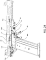
- the firing control mechanism in one embodiment includes a trigger mechanism or assembly including a trigger 40 pivotally mounted in frame 22 to fire control insert 80 via transverse trigger pin 41, and an axially (longitudinally) movable trigger bar 42 pivotally coupled to the trigger via transverse pivot pin 43 on an upright trigger pivot extension 46 (see, e.g. FIGS. 13 and 24 ).
- Pivot extension 46 may be disposed on or integrally formed with the trigger pivot pin 41 in some embodiments. Pulling trigger 40 rearward moves trigger bar 42 axially forward.
- the trigger 40 may be a dual trigger assembly in one embodiment including an outer trigger member and an inner safety trigger member pivotably movable relative thereto. Firing the firearm via a trigger pull in normal fashion requires each trigger to be intentionally pulled fully rearward. Operation of such safety trigger systems is well known in the art without further elaboration.
- An axially movable spring-biased firing pin 27 is supported by slide 24 and positioned for rearward retraction and forward movement when struck by a spring-biased striking member to strike a chambered cartridge C to discharge the firearm 20. Firing pin 27 is biased rearward toward a reset position by firing pin spring 27a. Firing pin spring 27a may be positioned concentrically around the forward portion of the axially elongated firing pin body. Spring 27a may be a helical compression coil spring in one embodiment, or other suitable type spring operable to bias the firing pin rearwards away from the chamber 30.
- the firing pin may have a diametrically narrowed front end and tip configured to contact the rear of cartridge C for detonating the cartridge, whereas the rear end of the firing pin may be diametrically enlarged relative thereto.
- the rear end may be exposed in a rear cavity 27b of the slide 24 where it can be reached and struck by the spring-biased striking member when released from engagement by sear 70. This drives the firing pin forward to strike and detonate the cartridge C in the usual manner known in the art.
- Cartridge C may be a centerfire cartridge in some embodiment; however, in other embodiments of the firearm the cartridge may be a rimfire cartridge.
- the spring-biased striking member may be a pivotably movable hammer 60 which is acted upon by the sear 70, which selectively retains or releases the hammer from the rearward cocked position in response to a trigger pull.
- the spring-biased striking member may be a linearly movable striker such as those disclosed in commonly-owned U.S. Patent 9,383,153 .
- the sear acts on a downwardly depending catch protrusion of the striker to selectively retain or release the striker.
- the striker replaces the firing pin and directly strikes a chambered cartridge.
- the dual-acting safety mechanism disclosed herein is therefore readily usable with either of the foregoing forms of striking members and therefore not limited in its applicability to a single means for striking a chambered cartridge to discharge the firearm.
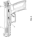
- a trigger return spring 44 may further be provided which in one embodiment may be a torsion spring that is mounted to trigger pin 41 and biases trigger 40 toward the fully forward ready-to-fire position (see, e.g. FIGS. 5 and 7B ).
- Trigger spring 44 may further include a rearwardly extending leg 44a (see, e.g. FIG. 13 ) configured to act on the underside of trigger bar 42 to bias the rear working end of the trigger bar upwards towards engagement with sear 70, as further described herein. In other embodiments, separate springs may be used to bias the trigger bar upwards.
- the firing control system or mechanism further includes hammer 60 for striking the firing pin 27 and sear 70 operably coupled to and cooperating with the hammer to fire the firearm via a trigger pull.
- the sear acts in a conventional manner to engage and retain the hammer 60 in a rearward pivoted cocked position until the trigger is pulled, and then disengages and releases the hammer via a trigger pull to strike firing pin 27 and discharge the firearm.
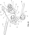
- FIG. 22 shows the interface and engagement surfaces between the sear and hammer which achieves this operation.
- FIGS. 31 and 32 show the sear in isolation and greater detail.
- sear 70 is pivotably mounted to fire control insert 80 to the rear of hammer 60 via a transverse sear pivot, which in one embodiment as shown may be formed by the cylindrical coupling rod 101 of the safety left actuator lever 100 (see also FIG. 28 ).
- a transverse sear pivot which in one embodiment as shown may be formed by the cylindrical coupling rod 101 of the safety left actuator lever 100 (see also FIG. 28 ).
- the safety lever coupling rod 101 is received through transversely open sear pin hole 72 formed through the body of the sear.
- Coupling rod 101 defines a transverse pivot axis.
- Sear 70 has a body including a main barrel portion 77 which defines cylindrical sear pin hole 72 extending transversely therethrough to receive safety left actuator lever coupling rod 101 therethrough, a vertically elongated operating extension arm 73 projecting upwards from the barrel portion, and a forwardly extending hammer engagement portion 78.
- Engagement portion 78 includes a primary and secondary hammer catch.
- the primary hammer catch comprises a wedge-shaped primary sear catch protrusion 76 configured to engage and retain hammer 60 in the rearward cocked position.
- the secondary hammer catch comprises an axially/horizontally elongated secondary sear catch arm 75 extending forwardly from the engagement portion and also configured to engage and retain hammer 60 in the rearward cocked position in the event the primary sear catch protrusion disengages accidently from the sear without the trigger being pulled.
- Secondary sear catch arm 75 projects forward beyond sear catch protrusion 76 and engages a laterally open secondary hammer notch 61 formed on hammer 60 (see, e.g. FIG. 12 ).
- the secondary sear catch arm 75 provides an added layer of security designed to avoid unintentional firing of the firearm.
- the primary sear catch protrusion 76 defines a laterally broadened and elongated catch surface 76A which is selectively engageable with primary hammer notch 62 formed on the lower rear portion of hammer 60 (see, e.g. FIG. 22 ) for retaining the hammer in the rearward cocked position.
- Hammer notch 62 may be rearward facing and defines an upward facing notch surface 62a which engages the downward facing sear catch surface 76a on sear 70 via a substantially flat-to-flat interface as shown.
- Sear 70 is biased in an upwards or upright direction and orientation towards engagement with the hammer by sear spring 71 (clockwise as viewed in FIG. 22 ). Accordingly, spring 71 biases sear catch protrusion 76 towards engagement with hammer notch 62.
- sear spring 104 may be a torsion spring having the coiled portion wound around left safety lever coupling rod 101. A downward extending leg 104a of spring 104 may be braced against a portion of the frame 22 and/or firing control insert 80.
- Hammer 60 includes an elongated upper striking portion 63 defining a substantially flat front facing striking surface 63a for striking the rear end of firing pin 27 to discharge the firearm, and lower operating portion 64 which defines the hammer notch 62 and notch surface 62a previously described herein.
- the lower operating portion further includes a transverse through pivot hole 65 which receives hammer pivot pin 66 is located approximately midway between the striking and operating portions in the central portion of the hammer body as shown.
- Hammer pivot pin 66 extends laterally and transversely to longitudinal axis LA through the fire control insert 80 and defines a corresponding transverse pivot axis of the hammer.
- the hammer pivot pin 66 and the sear pivot defined by safety left actuator lever coupling rod 101 are each oriented parallel to each other and perpendicularly transverse to the longitudinal axis.
- Hammer spring 69 is mounted in firing control insert 80 to a separate hammer spring pin 68 and biases the striking portion 63 of hammer 60 forward toward the firing pin 27.
- Spring 69 may be an elongated coil spring housed in firing control insert 80 including a rear loop 69a braced against the firing control insert housing and an upwardly extending legs 69b engaged in frontal spring notch 69c of the hammer lower operating portion 64 (see, e.g. FIGS. 12 and 22 ).
- Other types and arrangements of springs may be used to bias the hammer towards the forward firing position.
- Hammer 60 is movable between the forward firing position striking the firing pin 27 and the ready-to-fire rearward cocked position via the trigger bar 42 and sear 70 which mechanically couple the trigger 40 to hammer.
- Operating extension arm 73 of sear 70 extending vertically upwards from the sear body comprises a laterally/transversely extending actuation protrusion 74 at its end.
- the sear actuation protrusion 74 is oriented perpendicularly to the length of the extension arm and longitudinal axis LA of the firearm.
- Sear actuation protrusion 74 is selectively engageable with a corresponding forward facing trigger bar operating surface 42d formed on the rear end of trigger bar 42 for rotating the sear 70 via a trigger pull to release the hammer 60 and discharge the firearm 20.
- FIGS. 10-13 show trigger bar operating surface 42d axially aligned to engage sear actuation protrusion 74 when the trigger is pulled with the safety mechanism in the "fire" position.
- Operating surface 42d of trigger bar 42 may be defined by a rearwardly and upwardly extending trigger bar operating protrusion 42c formed on the rear working end portion 42b of the trigger bar, as best shown in FIGS. 33-35 .
- trigger bar operating protrusion 42c may be configured as a generally elongated flattened plate-like body which is both laterally and inwardly offset from the elongated linear forward portion 42a of the trigger bar by a blocking portion 42h extending laterally inwards from rear working end portion 42b.
- trigger bar 42 may have a generally flat and relatively thin plate-like structure overall having an axially elongated configuration (i.e. along the direction of longitudinal axis LA).
- the body may be monolithic in structure and formed of metal bent to shape to form the various operating appurtenances and features described herein.
- Trigger bar 42 extends along longitudinal axis LA from trigger 40 to the sear 70.
- the trigger bar 42 may be located on the right lateral side of the firearm between the outer frame 22 and inner fire control insert 80 (see, e.g. FIG. 24 ).
- Trigger bar 42 however may be movably supported by and part of the firing control insert 80 components.
- the front end portion comprises a pin hole 42e which is pinned to the trigger 40 as previously described herein.
- Rear working end portion 42b includes a downwardly open concavity 42i into which hammer pivot pin 66 protrudes to avoid interference with operation of the trigger bar.
- the blocking portion 42h which extends laterally inwards from rear working end portion 42b defines a forward facing blocking surface 42f configured to be selectively engaged by the safety rocker 140 when the safety mechanism is in the "safe" position.
- the safety rocker 140 further is operable to engage an inwardly projecting disconnect hook protrusion 42g formed on the bottom of the working end portion 42b.
- the disconnect hook protrusion allow the safety mechanism to disconnect or uncouple the trigger bar from the sear 70 such that a trigger pull cannot actuate the sear to discharge the firearm when the safety is in the "safe” position, as further described herein.
- the ambidextrous dual-acting safety mechanism comprises left actuator lever 100, right actuator lever 120, and safety rocker 140.
- the left and right actuator levers are operably coupled together such that moving one concomitantly moves the other, as further described herein.
- FIGS. 27-30 show the left and right actuator levers in isolation and detail.
- Left actuator lever 100 has a body including an axially elongated and cantilevered operating handle 103, detent lobe 104 depending downwardly therefrom, and cylindrical coupling rod 101 extending perpendicularly from the handle.
- the lever body may have a monolithic unitary structure in one embodiment.
- Handle 103 may have a textured surface to facilitate engagement by the user to change the condition or position of the safety mechanism between a "fire” position and a "safe” position.
- Coupling rod 101 has a generally cylindrical body and extends from the left side of the firearm frame 22 to the right side through the firing control insert 80 (left and right designations given from the viewpoint of the user looking forward from the rear of the firearm as held in the usual firing position downfield).
- the coupling rod 101 is rotatably coupled to firing control insert and frame.
- the coupling rod 101 may be located at the rear end portion 107 of the handle 103 in one embodiment to maximize the arc through which the lever 100 may be rotated.
- One end of rod 101 is fixedly coupled to handle 103, while the opposite end defines a terminal coupling end 102 configured to lockingly engage coupling socket 122 formed at the rear of the right actuator lever 120.
- Coupling rod 101 may be pinned to the right actuator lever via mounting pin 113 (see, e.g. FIG. 13 ).
- Detent lobe 104 of left actuator lever 100 is a vertically elongated protrusion including concave upper and lower detent surfaces 104a, 104b.
- the detent surfaces are vertically spaced apart and selectively engaged by a spring-biased detent plunger 105 acting in an axial direction.
- the detent surfaces 104a, 104b may face forward and the plunger is biased rearward towards the surfacef by detent spring 106 (see, e.g. FIG. 11 ).
- the opposite arrangement may be used in other possible embodiments.
- the detent plunger and spring may be mounted to the frame 22 and/or firing control insert 80. The detent surfaces and plunger act to maintain the safety mechanism in either of the "safe" or "fire” positions selected by the user.
- Right actuator lever 120 has a body including an axially elongated and cantilevered operating handle 121, transversely open coupling socket 122 formed at a rear end portion123 thereof, and an operating protrusion in the form of an operating extension arm 125 extending downwardly and forwardly from the rear end of the handle as shown.
- the rear end portion 123 which defines the coupling socket may be generally barrel shaped as shown and includes a pin hole 105 which receives the mounting pin 113 to lockingly coupled the coupling rod 101 from the left actuator lever 100 in place.
- the coupling end 102 of coupling rod 101 and socket 122 may have complementary configured non-circular profiles as shown to ensure non-rotational coupling between them in addition to the pinning.
- the right lever body may also have a monolithic unitary structure in one embodiment similarly to the left lever body.
- Handle 121 may have a textured surface to facilitate engagement by the user to change the condition or position of the safety mechanism between the "fire” and "safe” positions.
- the operating extension arm 125 is longitudinally elongated in structure and oriented in the axial direction along the longitudinal axis LA of the firearm. Operating extension arm 125 projects forwardly and downwardly from the rear end portion 123 of right actuator lever 120.
- extension arm protrusion 125 includes an operating pin 126 formed integrally with the protrusion. Pin 126 may be cylindrical and projects transversely/laterally outwards to engage an actuation recess 143 of safety rocker 140.
- safety rocker 140 in one embodiment has a generally flattened plate-like and longitudinally elongated body comprising a bifurcated rear end including rearwardly projecting upper and lower actuation prongs 141, 142 which define a rearwardly open actuation slot or recess 143.
- Recess 143 receives transversely oriented operating pin 126 of the right actuator lever extension arm 125. Moving the right actuator lever 120 upward and downwards in motions associated with the safe and fire positions of the safety mechanism causes the safety rocker in turn to rotate in an alternating toggle-action upward and downward.
- the upper actuation prong 141 is engageable with the forward facing blocking surface 42f of trigger bar 42 to block movement thereof when the safety mechanism is in the safe position and the upper action prong is in the upward position.
- Safety rocker 140 further comprises a forwardly projecting and longitudinally elongated operating protrusion 145 engaged with disconnect hook protrusion 42g on the trigger bar to lower and disengage the trigger bar from the sear via rotating the safety rocker.
- Protrusion 145 may be considered nose shaped in one embodiment with a rounded front end; however, other configurations which function similarly may be provided.
- Safety rocker 140 includes a transversely oriented pivot hole 144 which receives the right end of hammer pin 66 to pivotably mount the safety rocker to the firearm. In other possible embodiments, a separate safety rocker pivot pin may be provided. Pivot hole 144 is located about midway between the front and rear ends of the safety rocker as shown.
- the safety rocker is thus configured such that upward rotation of its rear end (e.g. actuation prongs 141, 142) rotates the operating protrusion 145 at front in an opposite downward direction to displace and force the trigger bar 42 downward, thereby disengaging the sear 70 from the trigger bar.
- actuation prongs 141, 142 rotates the operating protrusion 145 at front in an opposite downward direction to displace and force the trigger bar 42 downward, thereby disengaging the sear 70 from the trigger bar.
- the safety mechanism may be further operable to lock the slide in the forward closed breech position.
- left actuator lever 100 of the safety mechanism comprises a forward facing locking surface 108 which is selectively engageable with a corresponding locking surface 109 formed on the left bottom longitudinal edge 112 of slide 24.
- the slide locking surface 109 may be located in a downwardly open V-notch 110 formed on the slide edge 112.
- Locking surface 108 of lever 120 may be formed inwards from handle 103 near the base of the handle as shown and directly above the detent lobe 104 in one embodiment.
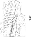
- FIG. 25 shows the safety in the fire position with the operating handle 103 rotated into the downward position.
- the mating locking surfaces are not engaged thereby allowing the slide to be retracted and the breech opened either manually by the user or automatically upon discharging the firearm.
- the handle 103 is raised to activate the safety mechanism ("safe" position) as shown in FIG. 26 with a closed breech, locking surfaces 108, 109 become mutually engaged to prevent retraction of the slide.
- FIGS. 10-13 show the safety mechanism in the "fire" position.
- Both operating handles 103, 121 of the left and right actuator levers 100, 120 respectively are in a horizontal position generally parallel to longitudinal axis LA of the firearm. This may also be considered to be the downward operational position within the pivotable arcuate range of rotation of the handles.
- Trigger bar 42 is in its upper position in which the actuation protrusion 74 on the upright operating extension arm 73 of sear 70 is axially aligned and engageable with operating protrusion 42c formed on the rear working end portion 42b of the trigger bar.
- Trigger bar operating surface 42d at the terminus of protrusion 42c may be slightly ajar and spaced rearward from the sear actuation protrusion 74 in the "fire" position, but nonetheless is axially aligned to engage and actuate the sear when the trigger 40 is fully pulled to discharge the firearm. It bears noting that the upward biasing action of trigger spring 44 positively forces the trigger bar upwards and into engagement with the sear actuation protrusion 74 as shown, which acts as a travel stop limiting the uppermost position of the trigger bar 42.
- the operating extension arm 125 of right actuator lever 120 is downward and the safety rocker 140 is not activated. Accordingly, in the "fire" position of the safety mechanism, the sear 70 remains engaged with the trigger bar 42 and the forward motion of the trigger bar via a trigger pull necessary to rotate the sear to release the hammer and fire the firearm is not blocked. Pulling the trigger 40 rearward rotates the sear 70 forwards about its pivot axis to disengage and release the hammer forward to strike the firing pin 27, which in turn strikes and detonates a chambered cartridge C.
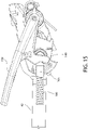
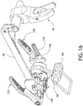
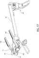
- FIGS. 14-21 show the safety mechanism in the "safe position.”
- either of the operating handles 103, 121 of the left and right actuator levers 100, 120 respectively may be raised to its upper operational position (which concomitantly moves the other handle similarly upward).
- Both handles 103, 121 are obliquely oriented to longitudinal axis LA of the firearm as shown. Raising the operating handles concomitantly rotates and raises the operating extension arm 125 of the right actuator lever 120 about coupling rod 101, which in turn concomitantly rotates the safety rocker 140 (clockwise as viewed in FIG. 14 ). This creates two simultaneous actions and motions of the safety mechanism.
- operating protrusion 145 of safety rocker 140 engaged with trigger bar 42 forces the trigger bar to its lower and downward position.
- operating protrusion 42c of the trigger bar now disconnects from and disengages the upright actuation protrusion 74 of sear 70.
- Trigger bar operating surface 42d is no longer axially aligned with the sear actuation protrusion 74 such that pulling the trigger 40 which moves the trigger bar forward can no longer engage and rotate the sear to discharge the firearm due to this misalignment.
- the upper actuation prong 141 of safety rocker 140 rotates upwards to block and/or engage forward facing blocking surface 42f of the trigger bar. Accordingly, the forward motion of the trigger bar 42 necessary to discharge the firearm is also arrested by the blocking action of the safety rocker. If the user attempts to pull the trigger, the positive engagement between the trigger bar blocking surface and safety rocker will arrest the motion of the trigger indicating to the user that the safety mechanism is activated (i.e. in "safe" position).
- the safety mechanism may be returned the "fire” mode or position by reversing the foregoing steps.
Landscapes
- Engineering & Computer Science (AREA)
- General Engineering & Computer Science (AREA)
- Aiming, Guidance, Guns With A Light Source, Armor, Camouflage, And Targets (AREA)
- Mechanical Control Devices (AREA)
- Toys (AREA)
Claims (30)
- Arme à feu (20) avec un mécanisme de sécurité à double action comprenant :un axe longitudinal (LA) ;une carcasse (22) ;un élément de percussion (60) disposé de manière mobile dans la carcasse (22), l'élément de percussion étant mobile entre une position armée vers l'arrière et une position de tir vers l'avant ;une gâchette (70) disposée de manière pivotante dans la carcasse (22), la gâchette étant configurée pour maintenir l'élément de percussion (60) dans la position armée vers l'arrière ;un mécanisme de détente comprenant une détente (40) et une barre de détente (42) couplée fonctionnellement à la gâchette (70), la barre de détente mobile devant actionner la gâchette pour libérer l'élément de percussion (60) de la position armée par une pression de la détente pour déclencher l'arme à feu (20) ;un mécanisme de sécurité fonctionnant manuellement comprenant au moins un premier levier d'actionnement (100, 120) mobile manuellement, monté de manière pivotante sur l'arme à feu (20) et interfacé fonctionnellement avec la barre de détente (42),caractérisée en ce que le mécanisme de sécurité comprend en outre un basculeur de sécurité (140) mobile de manière pivotante et couplé fonctionnellement avec le premier levier d'actionnement (100, 120), le basculeur de sécurité pouvant venir en prise avec la barre de détente et être actionné par déplacement du premier levier d'actionnement ;dans laquelle le mécanisme de sécurité est changeable par déplacement du premier levier d'actionnement (100, 120) entre : une position de tir dans laquelle la gâchette (70) vient en prise avec la barre de détente (42) pour déclencher l'arme à feu (20) en réponse à la pression de la détente ; et une position de sécurité dans laquelle le premier levier d'actionnement (100, 120) met la barre de détente (42) hors prise de la gâchette (70) et fait tourner le basculeur de sécurité (140) pour bloquer le déplacement de la barre de détente ce qui empêche l'arme à feu d'être déclenchée en réponse à la pression de la détente.
- Arme à feu (20) selon la revendication 1, dans laquelle la barre de détente (42) est mobile entre une première position de mise en prise avec la gâchette (70), et une seconde position de mise hors prise de la gâchette.
- Arme à feu (20) selon la revendication 1 ou 2, dans laquelle le changement du mécanisme de sécurité depuis la position de tir jusqu'à la position de sécurité fait tourner le basculeur de sécurité (140) ce qui met la barre de détente (42) hors prise de la gâchette (70).
- Arme à feu (20) selon la revendication 3, dans laquelle le premier levier d'actionnement (100, 120) comprend un bras d'extension de fonctionnement faisant saillie vers l'avant (125) venant en prise avec le basculeur de sécurité (140) et pouvant fonctionner pour faire tourner celui-ci entre une position de blocage lorsque le mécanisme de sécurité est dans la position de sécurité, et une position de non-blocage dans laquelle le basculeur de sécurité ne bloque pas le déplacement de la barre de détente (42) lorsque le mécanisme de sécurité est dans la position de tir.
- Arme à feu (20) selon l'une quelconque des revendications 1 à 4, dans laquelle le basculeur de sécurité (140) vient en prise avec une surface de blocage (42f) orientée transversalement de la barre de détente (42), pour bloquer le déplacement de celle-ci lorsque le mécanisme de sécurité est dans la position de sécurité.
- Arme à feu (20) selon la revendication 4, dans laquelle la rotation du basculeur de sécurité (140) depuis la position de non-blocage vers la position de blocage met simultanément la barre de détente (42) hors prise de la gâchette (70).
- Arme à feu (20) selon la revendication 4 ou 6, dans laquelle le basculeur de sécurité (140) est allongé et orienté longitudinalement, le basculeur de sécurité comprenant un évidement d'actionnement (143) ouvert qui vient en prise avec le bras d'extension (125) du premier levier d'actionnement (100, 120).
- Arme à feu (20) selon la revendication 7, dans laquelle le bras d'extension (125) comprend une goupille de fonctionnement (126) orientée transversalement qui vient en prise avec l'évidement d'actionnement (143) du basculeur de sécurité (140).
- Arme à feu (20) selon la revendication 8, dans laquelle le basculeur de sécurité (140) présente une extrémité arrière qui bifurque et qui comprend des broches d'actionnement (141, 142) supérieure et inférieure faisant saillie vers l'arrière, qui définissent l'évidement d'actionnement (143), la broche d'actionnement supérieure pouvant venir en prise avec la barre de détente (42) pour bloquer le déplacement de celle-ci lorsque le mécanisme de sécurité est dans la position de sécurité.
- Arme à feu (20) selon l'une quelconque des revendications 4 à 9, dans laquelle le basculeur de sécurité (140) comprend en outre une broche de fonctionnement (145) allongée et faisant saillie vers l'avant, qui vient en prise avec une saillie de crochet de déconnexion (42g) sur la barre de détente (42) pour mettre la barre de détente (42) hors prise de la gâchette (70) par rotation du basculeur de sécurité.
- Arme à feu (20) selon l'une quelconque des revendications 1 à 10, dans laquelle la gâchette (70) comprend en outre un bras de fonctionnement (73) s'étendant vers le haut qui peut venir en prise avec une saillie de fonctionnement (42c) correspondante s'étendant vers le haut de la barre de détente (42) pour faire tourner la gâchette en réponse à la pression de la détente.
- Arme à feu (20) selon la revendication 11, dans laquelle l'élément de percussion (60) est un chien mobile de manière pivotante autour d'une goupille de chien (66), et la gâchette (70) comprend en outre une saillie de saisie de gâchette principale (76) qui peut venir en prise avec une encoche de chien principale (62) sur le chien pour retenir le chien dans la position armée vers l'arrière.
- Arme à feu (20) selon la revendication 12, comprenant en outre un bras de saisie de gâchette secondaire (75) s'étendant vers l'avant depuis la gâchette et configuré pour venir en prise avec une encoche de chien secondaire (61) ouverte latéralement pour retenir le chien dans la position armée vers l'arrière dans l'éventualité où la saillie de saisie de gâchette principale (76) soit mise hors prise de la gâchette (70) sans que la détente (40) ne soit pressée.
- Arme à feu (20) selon la revendication 1, dans laquelle l'élément de percussion (60) est un chien mobile de manière pivotante autour d'une goupille de chien (66), et le basculeur de sécurité (140) est monté de manière pivotante sur la goupille de chien.
- Arme à feu (20) selon la revendication 1, comprenant en outre un second levier d'actionnement (100, 120) mobile manuellement et couplé fixement au premier levier d'actionnement (100, 120) de sorte que faire tourner le premier ou le second levier d'actionnement fait tourner l'autre.
- Arme à feu (20) selon la revendication 15, comprenant en outre un mécanisme d'arrêt à ressort agissant sur le second levier d'actionnement (100, 120), le mécanisme d'arrêt étant configuré pour retenir le mécanisme de sécurité dans les positions de sécurité et de tir.
- Arme à feu (20) selon la revendication 15, comprenant en outre une glissière (24) montée de manière mobile sur l'arme à feu pour un déplacement entre une position de culasse fermée vers l'avant et une position de culasse ouverte vers l'arrière, et dans laquelle le second levier d'actionnement (100, 120) comprend une surface de verrouillage de glissière (109) pouvant venir en prise de manière sélective avec une encoche de verrouillage (110) dans la glissière lorsque le mécanisme de sécurité est dans la position de sécurité.
- Arme à feu (20) selon l'une quelconque des revendications 1 à 17, dans laquelle le mécanisme de détente et le mécanisme de sécurité sont montés sur un insert de commande de tir (80) disposé de manière amovible dans la carcasse.
- Arme à feu (20) selon l'une quelconque des revendications 1 à 18, dans laquelle l'arme à feu est un pistolet à chargement automatique comprenant une glissière (24) à mouvement alternatif, mobile entre une position de culasse fermée vers l'avant et une position de culasse ouverte vers l'arrière.
- Arme à feu (20) selon la revendication 1, dans laquelle l'arme à feu est un pistolet à chargement automatique, comprenant :un insert de commande de tir (80) configuré pour être monté de manière amovible sur la carcasse et configuré pour former un logement pour des composants de mécanisme de tir ;une glissière (24) montée de manière mobile sur l'insert de commande de tir (80) pour un déplacement entre une position de culasse fermée vers l'avant et une position de culasse ouverte vers l'arrière ;un mécanisme de tir monté sur l'insert de commande de tir (80), le mécanisme de tir comprenant un chien (60) mobile de manière pivotante entre des positions de tir vers l'avant et armée vers l'arrière, une gâchette (70) rotative pouvant fonctionner pour retenir le chien dans la position armée et libérer le chien de celle-ci, une détente (40), et une barre de détente (42) reliant fonctionnellement la détente à la gâchette, la barre de détente mobile devant faire tourner la gâchette et libérer le chien de la position armée par une pression de la détente pour déclencher l'arme à feu (20) ;un mécanisme de sécurité manuel ambidextre comprenant un premier levier d'actionnement (120) pivotant, couplé fonctionnellement avec la barre de détente, un second levier d'actionnement (100) pivotant, couplé fonctionnellement au premier levier d'actionnement, et un basculeur de sécurité (140) mobile de manière pivotante couplé fonctionnellement avec le premier levier d'actionnement ;dans laquelle le mécanisme de sécurité est changeable manuellement par déplacement des premier ou second leviers d'actionnement (120, 100) entre : une position de tir dans laquelle la gâchette (70) vient en prise avec la barre de détente (42) pour déclencher l'arme à feu (20) en réponse à la pression de la détente ; et une position de sécurité dans laquelle le mécanisme de sécurité met la barre de détente (42) hors prise de la gâchette (70) et fait tourner le basculeur de sécurité (140) pour bloquer le déplacement de la barre de détente ce qui empêche l'arme à feu d'être déclenchée en réponse à la pression de la détente.
- Arme à feu selon la revendication 20, dans laquelle le second levier d'actionnement (100) comprend une surface de verrouillage de glissière (109) pouvant venir en prise de manière sélective avec une encoche de verrouillage (110) dans la glissière (24) lorsque le mécanisme de sécurité est dans la position de sécurité pour verrouiller la glissière dans la position de culasse fermée.
- Arme à feu selon la revendication 20 ou 21, comprenant en outre un mécanisme d'arrêt à ressort agissant sur le second levier d'actionnement (100), le mécanisme d'arrêt étant configuré pour retenir le mécanisme de sécurité dans les positions de sécurité et de tir.
- Arme à feu selon la revendication 22, dans laquelle le second levier d'actionnement (100) comprend un lobe d'arrêt (104) s'étendant vers le bas comprenant une paire de surfaces d'arrêt (104a, 104b) pouvant chacune venir en prise de manière sélective avec un poussoir d'arrêt (105) à ressort lorsque le mécanisme de sécurité est déplacé entre les positions de tir et de sécurité.
- Arme à feu selon l'une quelconque des revendications 20 à 23, dans laquelle le déplacement des premier ou second leviers d'actionnement (120, 100) pour changer le mécanisme de sécurité depuis la position de tir vers la position de sécurité abaisse la barre de détente (42) pour mettre la gâchette (70) hors prise de celle-ci pour empêcher le déclenchement de l'arme à feu.
- Arme à feu selon la revendication 24, dans laquelle le premier levier d'actionnement (120) comprend un bras d'extension (125) de fonctionnement faisant saillie vers l'avant qui fait tourner le basculeur de sécurité (140) pour forcer la barre de détente (42) vers le bas et mettre la gâchette (70) hors prise lorsque le mécanisme de sécurité est déplacé dans la position de sécurité.
- Arme à feu selon la revendication 25, dans laquelle le bras d'extension (125) fait tourner simultanément le basculeur de sécurité (140) depuis une première position dans laquelle un déplacement de la barre de détente (142) n'est pas bloqué, vers une seconde position dans laquelle bloque le déplacement vers l'avant de la barre de détente en réponse à la pression de la détente.
- Arme à feu selon la revendication 25, dans laquelle le basculeur de sécurité (140) est allongé longitudinalement et comprend un évidement d'actionnement (143) ouvert vers l'arrière qui reçoit le bras d'extension (125) du premier levier d'actionnement (120) au moins partiellement à l'intérieur de celui-ci pour actionner le basculeur de sécurité.
- Arme à feu selon la revendication 20, dans laquelle les premier et second leviers d'actionnement (120, 100) comprennent chacun des poignées de fonctionnement en porte-à-faux (121, 103) allongées longitudinalement, mobiles simultanément entre une position inférieure associée à la position de tir du mécanisme de sécurité, et une position supérieure associée à la position de sécurité du mécanisme de sécurité.
- Méthode pour faire fonctionner un mécanisme de sécurité pour arme à feu comprenant :la fourniture d'une arme à feu (20) comportant un axe longitudinal (LA), un élément de percussion (60) mobile entre des positions armée vers l'arrière et de tir vers l'avant, une gâchette (70) pouvant fonctionner pour retenir l'élément de percussion dans la position armée, une barre de détente (42) reliant fonctionnellement la gâchette à une détente (40) de sorte que presser la détente déplace la barre de détente qui en retour fait tourner la gâchette pour libérer l'élément de percussion pour déclencher l'arme à feu ;l'installation d'un mécanisme de sécurité comprenant un levier d'actionnement (120) interfacé fonctionnellement avec la barre de détente (42) dans une position de tir, la barre de détente étant dans une première position pouvant venir en prise avec la gâchette (70) pour actionner la gâchette en réponse à une pression de la détente (40) ;le déplacement du levier d'actionnement (120) pour placer le mécanisme de sécurité dans une position de sécurité ;la rotation d'un basculeur de sécurité (140) du mécanisme de sécurité avec le levier d'actionnement (120) ;le déplacement de la barre de détente (42) vers une seconde position par rotation du basculeur de sécurité (140), la barre de détente ne pouvant pas venir en prise avec la gâchette (70) pour actionner la gâchette en réponse à une pression de la détente ; etle blocage simultanément du déplacement de la barre de détente (42) avec le basculeur de sécurité (140).
- Méthode selon la revendication 29, dans laquelle la rotation du basculeur de sécurité (140) avec le levier d'actionnement (120) comprend l'élévation d'une extrémité arrière du basculeur de sécurité qui vient en prise avec la barre de détente (42) pour bloquer le déplacement de celle-ci, et l'abaissement d'une extrémité avant du basculeur de sécurité (140) qui vient en prise avec la barre de détente (42) et la déplace vers la seconde position.
Applications Claiming Priority (1)
| Application Number | Priority Date | Filing Date | Title |
|---|---|---|---|
| US202062975247P | 2020-02-12 | 2020-02-12 |
Publications (2)
| Publication Number | Publication Date |
|---|---|
| EP3865807A1 EP3865807A1 (fr) | 2021-08-18 |
| EP3865807B1 true EP3865807B1 (fr) | 2022-06-22 |
Family
ID=74595182
Family Applications (1)
| Application Number | Title | Priority Date | Filing Date |
|---|---|---|---|
| EP21156874.6A Active EP3865807B1 (fr) | 2020-02-12 | 2021-02-12 | Mécanisme de sécurité pour armes à feu |
Country Status (2)
| Country | Link |
|---|---|
| US (1) | US11578939B2 (fr) |
| EP (1) | EP3865807B1 (fr) |
Families Citing this family (6)
| Publication number | Priority date | Publication date | Assignee | Title |
|---|---|---|---|---|
| US10739095B2 (en) * | 2015-12-01 | 2020-08-11 | Mean L.L.C. | Firearm operating system |
| US10704853B2 (en) * | 2018-08-24 | 2020-07-07 | WHG Properties, LLC | Trigger assemblies for firearms |
| US11280570B2 (en) | 2019-03-11 | 2022-03-22 | James Matthew Underwood | Firearm operating mechanisms and bolt release |
| EP3990851B1 (fr) * | 2019-06-27 | 2025-02-19 | Sturm Ruger & Company, Inc. | Mécanisme de sécurité pour armes à feu |
| TR2023001948A2 (tr) * | 2022-02-22 | 2023-09-21 | Hs Produkt D O O | Manüel başparmak emni̇yeti̇ |
| US12480728B2 (en) * | 2023-04-12 | 2025-11-25 | Tyrant Designs CNC, LLC | Firearm trigger with safety blade |
Family Cites Families (34)
| Publication number | Priority date | Publication date | Assignee | Title |
|---|---|---|---|---|
| DE1919943A1 (de) * | 1969-04-19 | 1970-12-23 | Carl Walher | Schlagbolzensicherung fuer Feuerwaffen |
| IT1090110B (it) | 1977-10-28 | 1985-06-18 | Beretta Armi Spa | Pistola automatica perfezionata |
| US4590697A (en) * | 1984-06-25 | 1986-05-27 | Sturm, Ruger & Company, Inc. | Ambidextrous safety mechanism |
| US5903994A (en) | 1996-11-19 | 1999-05-18 | Tange; Mark L. | Normally-on safety on a pistol, and method of converting a pistol to include a normally-on safety |
| US6256918B1 (en) * | 1998-11-19 | 2001-07-10 | Atilla Szabo | Firing pin locking assembly for a semi-automatic handgun |
| US6718680B2 (en) * | 2000-03-20 | 2004-04-13 | Albert Roca | Semiautomatic handgun having multiple safeties |
| ITBS20010001A1 (it) | 2001-01-11 | 2002-07-11 | Beretta Armi Spa | Dispositivo di sicura per pistole |
| US6560909B2 (en) | 2001-06-22 | 2003-05-13 | Joseph Cominolli | Manual safety for linear striker fired semi-automatic or automatic pistols |
| US6588136B2 (en) * | 2001-10-11 | 2003-07-08 | Fn Mfg Llc | Decocking lever |
| AT412125B (de) | 2003-01-31 | 2004-09-27 | Glock Gaston | Sperrvorrichtung für eine pistole |
| US6948273B2 (en) | 2004-02-06 | 2005-09-27 | Henry Repeating Arms Company | Safety mechanism for gun |
| DE502004001472D1 (de) | 2004-02-19 | 2006-10-26 | Sat Swiss Arms Technology Ag | Sicherung für eine Handfeuerwaffe |
| US7243453B2 (en) | 2004-04-15 | 2007-07-17 | Sturm, Ruger & Company, Inc. | Pistol with firing pin locking mechanism |
| US7698845B2 (en) | 2004-12-16 | 2010-04-20 | New Colt Holding Corporation | Double action model 1911 pistol |
| US7810269B2 (en) | 2007-01-10 | 2010-10-12 | Smith & Wesson Corp. | Frame-mounted trigger safety and well extension |
| US7726059B2 (en) | 2007-03-07 | 2010-06-01 | Dov Pikielny | Lockable safety for firearm |
| US8033043B2 (en) | 2007-07-25 | 2011-10-11 | Sturm, Ruger & Company, Inc. | Lockable safety for striker-fired firearm |
| US8127481B2 (en) | 2007-09-26 | 2012-03-06 | Colt's Manufacturing Company Inc. | Model 1911 semiautomatic pistol thumb safety |
| US8677665B1 (en) | 2007-10-05 | 2014-03-25 | John F. Huber | Trigger assembly |
| US8296990B2 (en) | 2008-12-30 | 2012-10-30 | Smith & Wesson Corp. | Snap-on dovetail pistol sight |
| US8276502B1 (en) | 2010-01-18 | 2012-10-02 | Robert Wright | Ambidextrous safety lever |
| US9587897B1 (en) | 2010-02-19 | 2017-03-07 | George Huang | Interchangeable safety selector for firearms |
| US8464455B2 (en) * | 2011-01-07 | 2013-06-18 | Sturm, Ruger & Company, Inc. | Lockable safety for firearm |
| US8683729B2 (en) | 2011-04-22 | 2014-04-01 | Sig Sauer, Inc. | Ambidextrous thumb safety assembly |
| US8677667B2 (en) | 2011-12-16 | 2014-03-25 | David Kenneth Tatum | Ambidextrous thumb safety for a handgun |
| US8499482B1 (en) | 2012-06-12 | 2013-08-06 | Kimber Ip, Llc | Ambidextrous thumb safety |
| WO2015080775A1 (fr) * | 2013-09-10 | 2015-06-04 | Sturm, Ruger & Company, Inc. | Mécanisme de dispositif de blocage de tir pour une arme à feu |
| WO2015157753A1 (fr) * | 2014-04-11 | 2015-10-15 | Sturm, Ruger & Company, Inc. | Système de commande de tir pour armes à feu |
| US10126086B2 (en) | 2015-10-29 | 2018-11-13 | Evolution Gun Works, Inc. | Ambidextrous safety for a firearm |
| US10317159B2 (en) * | 2015-12-28 | 2019-06-11 | Sturm, Ruger & Company, Inc. | Variable barrel camming system for firearm |
| US10393459B2 (en) | 2016-10-04 | 2019-08-27 | Edward Tompkins | Modular receiver system for firearms and an adjustable and tool-less removable trigger assembly |
| US10030927B1 (en) * | 2017-02-28 | 2018-07-24 | Apex Tactical Specialties, Inc. | Sear system for a firearm |
| US10663245B2 (en) | 2017-07-26 | 2020-05-26 | Apex Tactical Specialties, Inc. | Trigger bar for a firearm |
| CN108917457B (zh) | 2018-09-17 | 2024-04-09 | 浙江新华机械制造有限公司 | 袖珍手枪 |
-
2021
- 2021-02-10 US US17/172,778 patent/US11578939B2/en active Active
- 2021-02-12 EP EP21156874.6A patent/EP3865807B1/fr active Active
Also Published As
| Publication number | Publication date |
|---|---|
| EP3865807A1 (fr) | 2021-08-18 |
| US20210247157A1 (en) | 2021-08-12 |
| US11578939B2 (en) | 2023-02-14 |
Similar Documents
| Publication | Publication Date | Title |
|---|---|---|
| EP3865807B1 (fr) | Mécanisme de sécurité pour armes à feu | |
| EP3397916B1 (fr) | Système de commande de tir pour arme à feu | |
| KR102584642B1 (ko) | 선택적 발사 총기 시스템 및 방법 | |
| US11598597B2 (en) | Safety mechanism for firearms | |
| EP3129739B1 (fr) | Système de commande de tir pour armes à feu | |
| US6374526B1 (en) | Firing pin block for pistol | |
| EP1586850B1 (fr) | Pistolet avec sécurité magasin-retiré | |
| US20250341372A1 (en) | Ambidextrous bolt release mechanism for firearm | |
| US9803940B2 (en) | Shell loading system for firearm | |
| US10309736B2 (en) | Shell loading system for firearm | |
| KR20200128525A (ko) | 화기를 위한 방아쇠 장치 | |
| US20250389503A1 (en) | Slide takedown and magazine disconnect assembly for firearms | |
| EP3948142B1 (fr) | Mécanisme de dispositif d'arrêtoir de culasse pour arme à feu | |
| US3845688A (en) | Sear-disconnector for firearms | |
| CA3037716C (fr) | Systemes et procedes d'arme a feu a feu selectif |
Legal Events
| Date | Code | Title | Description |
|---|---|---|---|
| PUAI | Public reference made under article 153(3) epc to a published international application that has entered the european phase |
Free format text: ORIGINAL CODE: 0009012 |
|
| STAA | Information on the status of an ep patent application or granted ep patent |
Free format text: STATUS: THE APPLICATION HAS BEEN PUBLISHED |
|
| AK | Designated contracting states |
Kind code of ref document: A1 Designated state(s): AL AT BE BG CH CY CZ DE DK EE ES FI FR GB GR HR HU IE IS IT LI LT LU LV MC MK MT NL NO PL PT RO RS SE SI SK SM TR |
|
| STAA | Information on the status of an ep patent application or granted ep patent |
Free format text: STATUS: REQUEST FOR EXAMINATION WAS MADE |
|
| 17P | Request for examination filed |
Effective date: 20211123 |
|
| RBV | Designated contracting states (corrected) |
Designated state(s): AL AT BE BG CH CY CZ DE DK EE ES FI FR GB GR HR HU IE IS IT LI LT LU LV MC MK MT NL NO PL PT RO RS SE SI SK SM TR |
|
| GRAP | Despatch of communication of intention to grant a patent |
Free format text: ORIGINAL CODE: EPIDOSNIGR1 |
|
| STAA | Information on the status of an ep patent application or granted ep patent |
Free format text: STATUS: GRANT OF PATENT IS INTENDED |
|
| RIC1 | Information provided on ipc code assigned before grant |
Ipc: F41A 17/46 20060101ALI20211216BHEP Ipc: F41A 19/44 20060101ALI20211216BHEP Ipc: F41A 19/12 20060101ALI20211216BHEP Ipc: F41A 17/56 20060101ALI20211216BHEP Ipc: F41A 17/32 20060101AFI20211216BHEP |
|
| INTG | Intention to grant announced |
Effective date: 20220111 |
|
| GRAS | Grant fee paid |
Free format text: ORIGINAL CODE: EPIDOSNIGR3 |
|
| GRAA | (expected) grant |
Free format text: ORIGINAL CODE: 0009210 |
|
| STAA | Information on the status of an ep patent application or granted ep patent |
Free format text: STATUS: THE PATENT HAS BEEN GRANTED |
|
| AK | Designated contracting states |
Kind code of ref document: B1 Designated state(s): AL AT BE BG CH CY CZ DE DK EE ES FI FR GB GR HR HU IE IS IT LI LT LU LV MC MK MT NL NO PL PT RO RS SE SI SK SM TR |
|
| REG | Reference to a national code |
Ref country code: GB Ref legal event code: FG4D |
|
| REG | Reference to a national code |
Ref country code: CH Ref legal event code: EP |
|
| REG | Reference to a national code |
Ref country code: DE Ref legal event code: R096 Ref document number: 602021000149 Country of ref document: DE |
|
| REG | Reference to a national code |
Ref country code: AT Ref legal event code: REF Ref document number: 1500019 Country of ref document: AT Kind code of ref document: T Effective date: 20220715 |
|
| REG | Reference to a national code |
Ref country code: IE Ref legal event code: FG4D |
|
| REG | Reference to a national code |
Ref country code: LT Ref legal event code: MG9D |
|
| REG | Reference to a national code |
Ref country code: NL Ref legal event code: MP Effective date: 20220622 |
|
| PG25 | Lapsed in a contracting state [announced via postgrant information from national office to epo] |
Ref country code: SE Free format text: LAPSE BECAUSE OF FAILURE TO SUBMIT A TRANSLATION OF THE DESCRIPTION OR TO PAY THE FEE WITHIN THE PRESCRIBED TIME-LIMIT Effective date: 20220622 Ref country code: NO Free format text: LAPSE BECAUSE OF FAILURE TO SUBMIT A TRANSLATION OF THE DESCRIPTION OR TO PAY THE FEE WITHIN THE PRESCRIBED TIME-LIMIT Effective date: 20220922 Ref country code: LT Free format text: LAPSE BECAUSE OF FAILURE TO SUBMIT A TRANSLATION OF THE DESCRIPTION OR TO PAY THE FEE WITHIN THE PRESCRIBED TIME-LIMIT Effective date: 20220622 Ref country code: HR Free format text: LAPSE BECAUSE OF FAILURE TO SUBMIT A TRANSLATION OF THE DESCRIPTION OR TO PAY THE FEE WITHIN THE PRESCRIBED TIME-LIMIT Effective date: 20220622 Ref country code: GR Free format text: LAPSE BECAUSE OF FAILURE TO SUBMIT A TRANSLATION OF THE DESCRIPTION OR TO PAY THE FEE WITHIN THE PRESCRIBED TIME-LIMIT Effective date: 20220923 Ref country code: FI Free format text: LAPSE BECAUSE OF FAILURE TO SUBMIT A TRANSLATION OF THE DESCRIPTION OR TO PAY THE FEE WITHIN THE PRESCRIBED TIME-LIMIT Effective date: 20220622 Ref country code: BG Free format text: LAPSE BECAUSE OF FAILURE TO SUBMIT A TRANSLATION OF THE DESCRIPTION OR TO PAY THE FEE WITHIN THE PRESCRIBED TIME-LIMIT Effective date: 20220922 |
|
| PG25 | Lapsed in a contracting state [announced via postgrant information from national office to epo] |
Ref country code: RS Free format text: LAPSE BECAUSE OF FAILURE TO SUBMIT A TRANSLATION OF THE DESCRIPTION OR TO PAY THE FEE WITHIN THE PRESCRIBED TIME-LIMIT Effective date: 20220622 Ref country code: LV Free format text: LAPSE BECAUSE OF FAILURE TO SUBMIT A TRANSLATION OF THE DESCRIPTION OR TO PAY THE FEE WITHIN THE PRESCRIBED TIME-LIMIT Effective date: 20220622 |
|
| PG25 | Lapsed in a contracting state [announced via postgrant information from national office to epo] |
Ref country code: NL Free format text: LAPSE BECAUSE OF FAILURE TO SUBMIT A TRANSLATION OF THE DESCRIPTION OR TO PAY THE FEE WITHIN THE PRESCRIBED TIME-LIMIT Effective date: 20220622 |
|
| PG25 | Lapsed in a contracting state [announced via postgrant information from national office to epo] |
Ref country code: SM Free format text: LAPSE BECAUSE OF FAILURE TO SUBMIT A TRANSLATION OF THE DESCRIPTION OR TO PAY THE FEE WITHIN THE PRESCRIBED TIME-LIMIT Effective date: 20220622 Ref country code: SK Free format text: LAPSE BECAUSE OF FAILURE TO SUBMIT A TRANSLATION OF THE DESCRIPTION OR TO PAY THE FEE WITHIN THE PRESCRIBED TIME-LIMIT Effective date: 20220622 Ref country code: RO Free format text: LAPSE BECAUSE OF FAILURE TO SUBMIT A TRANSLATION OF THE DESCRIPTION OR TO PAY THE FEE WITHIN THE PRESCRIBED TIME-LIMIT Effective date: 20220622 Ref country code: PT Free format text: LAPSE BECAUSE OF FAILURE TO SUBMIT A TRANSLATION OF THE DESCRIPTION OR TO PAY THE FEE WITHIN THE PRESCRIBED TIME-LIMIT Effective date: 20221024 Ref country code: ES Free format text: LAPSE BECAUSE OF FAILURE TO SUBMIT A TRANSLATION OF THE DESCRIPTION OR TO PAY THE FEE WITHIN THE PRESCRIBED TIME-LIMIT Effective date: 20220622 Ref country code: EE Free format text: LAPSE BECAUSE OF FAILURE TO SUBMIT A TRANSLATION OF THE DESCRIPTION OR TO PAY THE FEE WITHIN THE PRESCRIBED TIME-LIMIT Effective date: 20220622 Ref country code: CZ Free format text: LAPSE BECAUSE OF FAILURE TO SUBMIT A TRANSLATION OF THE DESCRIPTION OR TO PAY THE FEE WITHIN THE PRESCRIBED TIME-LIMIT Effective date: 20220622 |
|
| PG25 | Lapsed in a contracting state [announced via postgrant information from national office to epo] |
Ref country code: PL Free format text: LAPSE BECAUSE OF FAILURE TO SUBMIT A TRANSLATION OF THE DESCRIPTION OR TO PAY THE FEE WITHIN THE PRESCRIBED TIME-LIMIT Effective date: 20220622 Ref country code: IS Free format text: LAPSE BECAUSE OF FAILURE TO SUBMIT A TRANSLATION OF THE DESCRIPTION OR TO PAY THE FEE WITHIN THE PRESCRIBED TIME-LIMIT Effective date: 20221022 |
|
| REG | Reference to a national code |
Ref country code: DE Ref legal event code: R097 Ref document number: 602021000149 Country of ref document: DE |
|
| PG25 | Lapsed in a contracting state [announced via postgrant information from national office to epo] |
Ref country code: AL Free format text: LAPSE BECAUSE OF FAILURE TO SUBMIT A TRANSLATION OF THE DESCRIPTION OR TO PAY THE FEE WITHIN THE PRESCRIBED TIME-LIMIT Effective date: 20220622 |
|
| PG25 | Lapsed in a contracting state [announced via postgrant information from national office to epo] |
Ref country code: DK Free format text: LAPSE BECAUSE OF FAILURE TO SUBMIT A TRANSLATION OF THE DESCRIPTION OR TO PAY THE FEE WITHIN THE PRESCRIBED TIME-LIMIT Effective date: 20220622 |
|
| PLBE | No opposition filed within time limit |
Free format text: ORIGINAL CODE: 0009261 |
|
| STAA | Information on the status of an ep patent application or granted ep patent |
Free format text: STATUS: NO OPPOSITION FILED WITHIN TIME LIMIT |
|
| 26N | No opposition filed |
Effective date: 20230323 |
|
| PG25 | Lapsed in a contracting state [announced via postgrant information from national office to epo] |
Ref country code: SI Free format text: LAPSE BECAUSE OF FAILURE TO SUBMIT A TRANSLATION OF THE DESCRIPTION OR TO PAY THE FEE WITHIN THE PRESCRIBED TIME-LIMIT Effective date: 20220622 |
|
| PG25 | Lapsed in a contracting state [announced via postgrant information from national office to epo] |
Ref country code: MC Free format text: LAPSE BECAUSE OF FAILURE TO SUBMIT A TRANSLATION OF THE DESCRIPTION OR TO PAY THE FEE WITHIN THE PRESCRIBED TIME-LIMIT Effective date: 20220622 |
|
| PG25 | Lapsed in a contracting state [announced via postgrant information from national office to epo] |
Ref country code: LU Free format text: LAPSE BECAUSE OF NON-PAYMENT OF DUE FEES Effective date: 20230212 |
|
| REG | Reference to a national code |
Ref country code: IE Ref legal event code: MM4A |
|
| PG25 | Lapsed in a contracting state [announced via postgrant information from national office to epo] |
Ref country code: IE Free format text: LAPSE BECAUSE OF NON-PAYMENT OF DUE FEES Effective date: 20230212 Ref country code: FR Free format text: LAPSE BECAUSE OF NON-PAYMENT OF DUE FEES Effective date: 20230228 |
|
| PG25 | Lapsed in a contracting state [announced via postgrant information from national office to epo] |
Ref country code: BG Free format text: LAPSE BECAUSE OF FAILURE TO SUBMIT A TRANSLATION OF THE DESCRIPTION OR TO PAY THE FEE WITHIN THE PRESCRIBED TIME-LIMIT Effective date: 20220622 |
|
| PG25 | Lapsed in a contracting state [announced via postgrant information from national office to epo] |
Ref country code: BG Free format text: LAPSE BECAUSE OF FAILURE TO SUBMIT A TRANSLATION OF THE DESCRIPTION OR TO PAY THE FEE WITHIN THE PRESCRIBED TIME-LIMIT Effective date: 20220622 |
|
| PG25 | Lapsed in a contracting state [announced via postgrant information from national office to epo] |
Ref country code: CY Free format text: LAPSE BECAUSE OF FAILURE TO SUBMIT A TRANSLATION OF THE DESCRIPTION OR TO PAY THE FEE WITHIN THE PRESCRIBED TIME-LIMIT; INVALID AB INITIO Effective date: 20210212 |
|
| PG25 | Lapsed in a contracting state [announced via postgrant information from national office to epo] |
Ref country code: HU Free format text: LAPSE BECAUSE OF FAILURE TO SUBMIT A TRANSLATION OF THE DESCRIPTION OR TO PAY THE FEE WITHIN THE PRESCRIBED TIME-LIMIT; INVALID AB INITIO Effective date: 20210212 |
|
| GBPC | Gb: european patent ceased through non-payment of renewal fee |
Effective date: 20250212 |
|
| PG25 | Lapsed in a contracting state [announced via postgrant information from national office to epo] |
Ref country code: TR Free format text: LAPSE BECAUSE OF FAILURE TO SUBMIT A TRANSLATION OF THE DESCRIPTION OR TO PAY THE FEE WITHIN THE PRESCRIBED TIME-LIMIT Effective date: 20220622 |
|
| PG25 | Lapsed in a contracting state [announced via postgrant information from national office to epo] |
Ref country code: GB Free format text: LAPSE BECAUSE OF NON-PAYMENT OF DUE FEES Effective date: 20250212 |
|
| REG | Reference to a national code |
Ref country code: CH Ref legal event code: U11 Free format text: ST27 STATUS EVENT CODE: U-0-0-U10-U11 (AS PROVIDED BY THE NATIONAL OFFICE) Effective date: 20260301 |
|
| PGFP | Annual fee paid to national office [announced via postgrant information from national office to epo] |
Ref country code: DE Payment date: 20260220 Year of fee payment: 6 |
|
| PGFP | Annual fee paid to national office [announced via postgrant information from national office to epo] |
Ref country code: AT Payment date: 20260218 Year of fee payment: 6 |
|
| PGFP | Annual fee paid to national office [announced via postgrant information from national office to epo] |
Ref country code: BE Payment date: 20260220 Year of fee payment: 6 Ref country code: IT Payment date: 20260205 Year of fee payment: 6 |
|
| PGFP | Annual fee paid to national office [announced via postgrant information from national office to epo] |
Ref country code: CH Payment date: 20260301 Year of fee payment: 6 |