EP3867727B1 - Druckregler mit eingebautem sicherheitsventil zur druckentlastung im fall von überdruck stromabwärts - Google Patents
Druckregler mit eingebautem sicherheitsventil zur druckentlastung im fall von überdruck stromabwärts Download PDFInfo
- Publication number
- EP3867727B1 EP3867727B1 EP18819176.1A EP18819176A EP3867727B1 EP 3867727 B1 EP3867727 B1 EP 3867727B1 EP 18819176 A EP18819176 A EP 18819176A EP 3867727 B1 EP3867727 B1 EP 3867727B1
- Authority
- EP
- European Patent Office
- Prior art keywords
- downstream
- piston
- pressure regulator
- upstream
- pressure chamber
- Prior art date
- Legal status (The legal status is an assumption and is not a legal conclusion. Google has not performed a legal analysis and makes no representation as to the accuracy of the status listed.)
- Active
Links
Images


Classifications
-
- F—MECHANICAL ENGINEERING; LIGHTING; HEATING; WEAPONS; BLASTING
- F17—STORING OR DISTRIBUTING GASES OR LIQUIDS
- F17C—VESSELS FOR CONTAINING OR STORING COMPRESSED, LIQUEFIED OR SOLIDIFIED GASES; FIXED-CAPACITY GAS-HOLDERS; FILLING VESSELS WITH, OR DISCHARGING FROM VESSELS, COMPRESSED, LIQUEFIED, OR SOLIDIFIED GASES
- F17C13/00—Details of vessels or of the filling or discharging of vessels
- F17C13/04—Arrangement or mounting of valves
-
- G—PHYSICS
- G05—CONTROLLING; REGULATING
- G05D—SYSTEMS FOR CONTROLLING OR REGULATING NON-ELECTRIC VARIABLES
- G05D16/00—Control of fluid pressure
- G05D16/04—Control of fluid pressure without auxiliary power
- G05D16/10—Control of fluid pressure without auxiliary power the sensing element being a piston or plunger
- G05D16/103—Control of fluid pressure without auxiliary power the sensing element being a piston or plunger the sensing element placed between the inlet and outlet
-
- G—PHYSICS
- G05—CONTROLLING; REGULATING
- G05D—SYSTEMS FOR CONTROLLING OR REGULATING NON-ELECTRIC VARIABLES
- G05D16/00—Control of fluid pressure
- G05D16/04—Control of fluid pressure without auxiliary power
- G05D16/0402—Control of fluid pressure without auxiliary power with two or more controllers mounted in series
-
- G—PHYSICS
- G05—CONTROLLING; REGULATING
- G05D—SYSTEMS FOR CONTROLLING OR REGULATING NON-ELECTRIC VARIABLES
- G05D16/00—Control of fluid pressure
- G05D16/04—Control of fluid pressure without auxiliary power
- G05D16/10—Control of fluid pressure without auxiliary power the sensing element being a piston or plunger
- G05D16/107—Control of fluid pressure without auxiliary power the sensing element being a piston or plunger with a spring-loaded piston in combination with a spring-loaded slideable obturator that move together over range of motion during normal operation
-
- F—MECHANICAL ENGINEERING; LIGHTING; HEATING; WEAPONS; BLASTING
- F17—STORING OR DISTRIBUTING GASES OR LIQUIDS
- F17C—VESSELS FOR CONTAINING OR STORING COMPRESSED, LIQUEFIED OR SOLIDIFIED GASES; FIXED-CAPACITY GAS-HOLDERS; FILLING VESSELS WITH, OR DISCHARGING FROM VESSELS, COMPRESSED, LIQUEFIED, OR SOLIDIFIED GASES
- F17C2205/00—Vessel construction, in particular mounting arrangements, attachments or identifications means
- F17C2205/03—Fluid connections, filters, valves, closure means or other attachments
- F17C2205/0302—Fittings, valves, filters, or components in connection with the gas storage device
- F17C2205/0323—Valves
- F17C2205/0332—Safety valves or pressure relief valves
-
- F—MECHANICAL ENGINEERING; LIGHTING; HEATING; WEAPONS; BLASTING
- F17—STORING OR DISTRIBUTING GASES OR LIQUIDS
- F17C—VESSELS FOR CONTAINING OR STORING COMPRESSED, LIQUEFIED OR SOLIDIFIED GASES; FIXED-CAPACITY GAS-HOLDERS; FILLING VESSELS WITH, OR DISCHARGING FROM VESSELS, COMPRESSED, LIQUEFIED, OR SOLIDIFIED GASES
- F17C2205/00—Vessel construction, in particular mounting arrangements, attachments or identifications means
- F17C2205/03—Fluid connections, filters, valves, closure means or other attachments
- F17C2205/0302—Fittings, valves, filters, or components in connection with the gas storage device
- F17C2205/0338—Pressure regulators
-
- F—MECHANICAL ENGINEERING; LIGHTING; HEATING; WEAPONS; BLASTING
- F17—STORING OR DISTRIBUTING GASES OR LIQUIDS
- F17C—VESSELS FOR CONTAINING OR STORING COMPRESSED, LIQUEFIED OR SOLIDIFIED GASES; FIXED-CAPACITY GAS-HOLDERS; FILLING VESSELS WITH, OR DISCHARGING FROM VESSELS, COMPRESSED, LIQUEFIED, OR SOLIDIFIED GASES
- F17C2205/00—Vessel construction, in particular mounting arrangements, attachments or identifications means
- F17C2205/03—Fluid connections, filters, valves, closure means or other attachments
- F17C2205/0302—Fittings, valves, filters, or components in connection with the gas storage device
- F17C2205/0382—Constructional details of valves, regulators
- F17C2205/0385—Constructional details of valves, regulators in blocks or units
-
- F—MECHANICAL ENGINEERING; LIGHTING; HEATING; WEAPONS; BLASTING
- F17—STORING OR DISTRIBUTING GASES OR LIQUIDS
- F17C—VESSELS FOR CONTAINING OR STORING COMPRESSED, LIQUEFIED OR SOLIDIFIED GASES; FIXED-CAPACITY GAS-HOLDERS; FILLING VESSELS WITH, OR DISCHARGING FROM VESSELS, COMPRESSED, LIQUEFIED, OR SOLIDIFIED GASES
- F17C2221/00—Handled fluid, in particular type of fluid
- F17C2221/01—Pure fluids
- F17C2221/012—Hydrogen
-
- Y—GENERAL TAGGING OF NEW TECHNOLOGICAL DEVELOPMENTS; GENERAL TAGGING OF CROSS-SECTIONAL TECHNOLOGIES SPANNING OVER SEVERAL SECTIONS OF THE IPC; TECHNICAL SUBJECTS COVERED BY FORMER USPC CROSS-REFERENCE ART COLLECTIONS [XRACs] AND DIGESTS
- Y02—TECHNOLOGIES OR APPLICATIONS FOR MITIGATION OR ADAPTATION AGAINST CLIMATE CHANGE
- Y02E—REDUCTION OF GREENHOUSE GAS [GHG] EMISSIONS, RELATED TO ENERGY GENERATION, TRANSMISSION OR DISTRIBUTION
- Y02E60/00—Enabling technologies; Technologies with a potential or indirect contribution to GHG emissions mitigation
- Y02E60/30—Hydrogen technology
- Y02E60/32—Hydrogen storage
Definitions
- the present invention relates to a gas regulator, as well as to a device for filling and withdrawing gas provided with such a regulator.
- a gas filling and withdrawal device comprises a withdrawal circuit provided with a storage connector connected to a pressurized gas storage container and a withdrawal connector connected to a gas withdrawal member at reduced pressure, and a filling circuit provided with a shaped filling connector for connection with a pressurized gas source for filling the storage container.
- the invention finds a particular, and non-limiting, application in the filling and withdrawal of gaseous hydrogen to supply a fuel cell type withdrawal device, in particular within a vehicle.
- WO 2013/135983 discloses a valve for filling and withdrawing gas, in which there is provided a safety circuit connected to the withdrawal circuit and comprising a safety valve to evacuate the contents of the tank to the outside in the event of a dangerous situation (temperature and/ or excessive pressure).
- the invention proposes a pressure reducer which incorporates a relief valve configured for a relief towards a leak circuit in the event of overpressure downstream, that is to say in the event of the downstream pressure exceeding a pressure predefined threshold.
- a downstream overpressure is likely to damage the equipment, and in particular the seals with the consequence of leaks.
- Such leaks can be particularly critical in the context of devices for filling and withdrawing gaseous hydrogen, in particular within a vehicle transporting people.
- the object of the present invention is in particular to propose a regulator which incorporates such a relief valve in the event of overpressure, that is to say that the regulator has its own relief valve, which contributes to increased safety and compactness.
- Another object of the invention is to provide a reliable regulator for expanding a gas between an upstream pressure of the order of 350 to 700 bars and a downstream pressure of the order of 10 to 30 bars, and also for expanding a gas between an upstream pressure of the order of 10 to 30 bars and a downstream pressure of the order of 0.5 to 5 bars.
- Another object of the invention is to provide a pressure reducer suitable for a filling and withdrawal device that is both bulky and light in weight.
- this regulator incorporates a relief valve configured for relief to a leak circuit in the event of overpressure downstream, where this relief valve comprises the relief valve formed at the valve stem, the relief seat formed at the level of the piston, and the second return member.
- the second return member extends inside the first return member.
- the first return member and the second return member are helical springs.
- the plate is formed by a circlip tightened around the valve stem.
- this plate is welded or crimped onto the valve stem, or else this plate is integral with the valve stem.
- the upper portion of the upstream body is provided with an external thread for fastening by screwing into a bore.
- the upstream body has the upper portion extended by a lower portion, where the upper portion faces the piston, and said lower portion has a lower dome resting on the bottom of a bore for an inlet of gas, where this lower dome is provided with side holes opening into the high pressure chamber.
- the lower cupola has an upper face facing the lower end of the internal channel of the upper portion of the upstream body, and a cavity is formed in this upper face to form the expansion seat.
- the lower portion of the upstream body comprises a cylindrical wall which surrounds the upper face of the lower dome, where this cylindrical wall is provided with side holes opening into the high pressure chamber.
- the downstream body forms a cover or stopper accessible from the outside of a body.
- the downstream body has two O-ring seals on the outer periphery inside a bore, and a leak pipe connected to the leak circuit opens into the bore between the two seals.
- the downstream body is fixed by screwing inside a bore.
- the regulator comprises a safety system with manual reset configured to automatically close the communication between the low pressure chamber and the high pressure chamber when the downstream pressure in the low pressure chamber drops below a pressure predefined low threshold corresponding to an increase in the gas flow at the outlet of the regulator, in particular associated with a leak downstream (and in particular with a leak in a withdrawal device placed downstream of the regulator).
- This low threshold pressure can be established by considering a maximum value of gas flow at the outlet of the regulator which is considered as a high threshold not to be exceeded for the flow because reflecting a malfunction at the level of the withdrawal device which may correspond to a leak.
- the shutter finger is mounted to slide in an orifice made through it in the downstream body.
- the obturator finger has two O-ring seals on the outer periphery inside the orifice of the downstream body, a leak pipe connected to the leak circuit is formed in the downstream body by opening into said orifice between the two seals.
- the safety system comprises an adjustment screw screwed into a thread provided in the orifice of the downstream body to allow the shutter finger to be moved selectively by screwing/unscrewing the adjustment screw which comes into abutment on the shutter finger.
- the safety system comprises a hollow stop screw screwed into a thread provided in the orifice of the downstream body to form an upper stop stop for the adjustment screw, and a lower stop stop for the adjustment screw is formed by an internal shoulder in said orifice.
- the withdrawal circuit comprises a first regulator and a second regulator in series, where each regulator is in accordance with the invention.
- only the second regulator incorporates a safety system with manual reset as described above.
- the invention also relates to a use of a filling and withdrawal device according to the invention, in which the storage connection is connected to a pressurized hydrogen gas storage container and the withdrawal connection is connected to a fuel cell type withdrawal member.
- the withdrawal circuit 2 comprises successively, starting from the upstream end 21, a controlled isolation valve 4, a first regulator 5 and a second regulator 6.
- the withdrawal circuit 2 also comprises , upstream of the controlled isolation valve 4, a temperature sensor 23 and a pressure sensor 24.
- the first regulator 5 is associated with, or incorporates, a relief valve 50 disposed downstream between the withdrawal circuit 2 and a leakage circuit 10, where this relief valve 50 is configured for a discharge towards the leakage circuit 10 in case of overpressure downstream, that is to say in the event of the downstream pressure being exceeded beyond a first predefined threshold pressure (also called adjustment value or calibration value).
- a first predefined threshold pressure also called adjustment value or calibration value
- the second regulator 6 is associated with, or incorporates, a relief valve 60 disposed downstream between the withdrawal circuit 2 and the leakage circuit 10, where this relief valve 60 is configured for a discharge towards the leakage circuit 10 in case of overpressure downstream, that is to say in the event of the downstream pressure being exceeded beyond a second predefined threshold pressure (also called adjustment value or calibration value).
- a second predefined threshold pressure also called adjustment value or calibration value
- This second regulator 6 is followed by a flow limiter 600 with a safety system 601 with manual reset to close the withdrawal circuit 2 in the event of a drop in the downstream pressure.
- the device 1 also comprises a filling circuit 7 comprising an upstream end 71 provided with a filling connector 8 shaped for connection with a source of gas SO under pressure for filling the storage container RE, and a downstream end 72 connected at the upstream end 21 of the withdrawal circuit 2.
- This safety circuit 9 includes, in parallel, a high pressure safety valve 93, a high temperature safety valve 94 and a purge valve 95 with flow limiter.
- the main function of the purge valve 95 is to allow controlled emptying of the storage container RE.
- the safety circuit 9 and the leakage circuit 10 are in communication, and together form one and the same circuit connected to the outside EXT.
- the rest of the description relates to an embodiment of this device 1, in a compact, light, reliable and secure version.
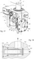
- This device 1 comprises a body 13 in which are formed bores forming pipes of the withdrawal circuit 2, of the filling 7, of the leakage circuit 10 and of the safety circuit 9, as well as receiving cavities for the various organs of the device 1.
- the storage connector 3 comprises a cylindrical connector 30 projecting from one side which is crossed by a main pipe 31 connected to the upstream end 21 of the withdrawal circuit 2, this connector 30 being intended to be connected to the storage container RE so that the gas flows in the main pipe 31.
- the shape of the connector 30 will depend on the connection interface of the storage container RE.
- the storage connector 3 also comprises a leak pipe 32 connected to the leak circuit 10 and emerging between two concentric seals 33, 34; these seals 33, 34 being positioned around the connector 30.
- a double sealing barrier is provided between the leak pipe 32 for optimum safety in the event of a leak at the level of the connector 30.
- the controlled isolation valve 4 comprises a valve 40 controlled by a motor member 41 between a closed position of the withdrawal circuit 2 and an open position of the withdrawal circuit, with the complementary action of a return member 42 which urges the valve 40 towards the closed position in the absence of actuation of the motor member 41.
- the valve 40 comprises a piston 43 movable under the action of the motor member 41, this piston 43 having an isolation valve 44 which rests on a seat 45.
- the motor member 41 controls the movement of the piston 43 in the direction of a detachment of the isolation valve 44 vis-à-vis the seat 45 for an opening of the valve 40 between its inlet 46 and its outlet 47.
- the return member 42 in particular of the helical spring type, exerts as for him a force on the piston 43 to urge it in the direction of a regluing of the isolation valve 44 on the seat 45 for a closure of the valve 40.
- the valve 40 incorporates a leak pipe 48 connected to the leak circuit 10 and arranged upstream of the isolation valve 44, to evacuate to the leak circuit 10 any leaks at the level of the bore receiving the valve 40 and also at the level of the movable piston 43.
- This leak pipe 48 is framed by seals 480, 481, 482 which guarantee a double sealing barrier in the management of leaks.
- the valve 40 incorporates another leak pipe 49 (visible on the figure 11 ) connected to the leakage circuit 10 and arranged downstream of the valve isolation 44, to evacuate to the leak circuit 10 any leaks at the bore receiving the valve 40 and also at the piston 43 mobile.
- This leak pipe 49 is framed by seals 490, 491 which guarantee a double sealing barrier in the management of leaks.
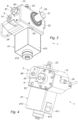
- the motor member 41 is mounted in a motor casing 410 fixed to the body 13 and an electrical outlet 411 is provided on the exterior of the motor casing 410.
- a knob 412 is also provided on the exterior of the casing 410, where this knob 412 makes it possible to deactivate and withdraw the motor member 41, so that only the return member 42 acts in the direction of closing the valve 40.
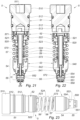
- the first regulator 5 is described below with reference to the figures 21 to 23 , where this first regulator 5 is mounted inside a bore whose bottom is in communication with the outlet of the valve 40.
- a leak pipe 17 (visible on the figure 10 ) formed in the body 13 is connected to the leakage circuit 10 and opens into the bore of the first regulator 5 between the two seals 512, again with a double sealing barrier.
- This first regulator 5 comprises a static upstream body 53 having an upper portion 54 extended by a lower portion 55, where the upper portion 54 faces the piston 52 so that the intermediate chamber 524 is delimited between the piston 52 and the upper portion 54 of the upstream body 53.
- the intermediate chamber 524 is connected to the leakage circuit 10 or to the safety circuit 9, via a discharge pipe 14 provided in the body 13 and visible on the figure 17 And 18 .
- the upper portion 54 is provided with an external thread 540 for fixing by screwing into the body 13, and more specifically fixing to the bottom of the corresponding bore, until this upper portion 54 is in abutment on a shoulder inside the bore via a seal 541.
- the upstream body 53 delimits with the bottom of the bore, under the internal shoulder, a high pressure chamber 56 at the inlet of the first regulator 5, this high pressure chamber 56 being connected to the outlet of the valve 40.
- the upper portion 54 has an internal through channel 542 having an upper end which opens into the intermediate chamber 524 and a lower end which opens into the high pressure chamber 56.
- the lower portion 55 has a lower dome 550 resting on the bottom of the bore for an EN inlet of the high pressure gas, where this lower dome 550 is provided with side holes 551 opening into the high pressure chamber 56.
- the lower dome 550 has an upper face facing the lower end of the internal channel 542, and a cavity is formed in this upper face to form a relaxation seat 552.
- the lower portion 55 comprises a cylindrical wall 553 which surrounds the upper face of the lower dome 550, where this cylindrical wall 553 is provided with side holes 554 opening into the high pressure chamber 56.
- the gas enters the interior of the lower dome 550 as shown schematically by the arrow EN on the figure 21 , then the gas leaves the high pressure chamber 56 through the side holes 551 and enters at the level of the expansion seat 552 through the side holes 554 as shown schematically by the arrow CH on the figure 21 .
- This path of the gas advantageously contributes to the desired gas expansion function.
- This first regulator 5 also comprises a first return member 58, in this case a helical spring, compressed between the piston 52 and the upstream body 53 and urging the piston 52 in the direction of the downstream body 51 (in other words in the direction of pressing piston 52 against downstream body 51).
- a first return member 58 in this case a helical spring, compressed between the piston 52 and the upstream body 53 and urging the piston 52 in the direction of the downstream body 51 (in other words in the direction of pressing piston 52 against downstream body 51).
- This first regulator 5 also comprises a second return member 59, in this case a helical spring, compressed between the piston 52 and a plate 573 integral with the valve stem 57.
- This second return member 59 extends inside the first return member 58, and the plate 573 can for example be formed by a circlip tightened around the valve stem valve 57.
- This second return member 59 urges the valve stem 57, relative to the piston 52, in the direction of a pressing of the relief valve 571 against the relief seat 521, in other words in the direction of the relief valve 571 to the upstream closed position.
- the following description relates to the operation of the first regulator 5.
- the relief valve 571 and the second return member 59 together form the relief valve 50 mentioned above with reference to the figure 1 .
- the second regulator 6 is described below with reference to the figures 24 to 28 , where this second regulator 6 is mounted inside a bore whose bottom is in communication with the outlet of the first regulator 5.
- a leak line 18 (visible on the figure 10 ) formed in the body 13 is connected to the leakage circuit 10 and opens into the bore of the second regulator 6 between the two seals 612, again with a double sealing barrier.
- This second regulator 6 comprises a static upstream body 63 having an upper portion 64 extended by a lower portion 65, where the upper portion 64 faces the piston 62 so that the intermediate chamber 624 is delimited between the piston 62 and the upper portion 64 of the upstream body 63.
- the intermediate chamber 624 is connected to the leakage circuit 10 or to the safety circuit 9, via a discharge pipe 15 arranged in the body 13 and visible on the figure 16 And 18 .
- the upper portion 64 is provided with an external thread 640 for fixing by screwing into the body 13, and more specifically fixing to the bottom of the corresponding bore, until this upper portion 64 is in abutment on a shoulder inside the bore via a seal 641.
- the upstream body 63 delimits with the bottom of the bore, under the internal shoulder, a high pressure chamber 66 at the inlet of the second regulator 6, this high pressure chamber 66 being connected to the outlet of the first regulator 5, in other words to the low pressure chamber 513 of this first regulator 5.
- the upper portion 64 has an internal through channel 642 having an upper end which opens into the intermediate chamber 624 and a lower end which opens into the high pressure chamber 66.
- the lower portion 65 has a lower dome 650 resting on the bottom of the bore for an EN inlet of the high pressure gas, where this lower dome 650 is provided with side holes 651 opening into the high pressure chamber 66.
- the lower dome 650 has an upper face facing the lower end of the internal channel 642, and a cavity is formed in this upper face to form a relaxation seat 652.
- the lower portion 65 comprises a cylindrical wall 653 which surrounds the upper face of the lower dome 650, where this wall cylindrical 653 is provided with side holes 654 opening into the high pressure chamber 66.
- the gas enters inside the lower dome 650, then the gas leaves the high pressure chamber 66 through the side holes 651 and enters at the level of the expansion seat 652 through the side holes 654.
- This path gas advantageously participates in the desired gas expansion function.
- This second regulator 6 also comprises a first return member 68, in this case a helical spring, compressed between the piston 62 and the upstream body 63 and urging the piston 62 in the direction of the downstream body 61 (In other words in the direction of pressing the piston 62 against the downstream body 61).
- a first return member 68 in this case a helical spring, compressed between the piston 62 and the upstream body 63 and urging the piston 62 in the direction of the downstream body 61 (In other words in the direction of pressing the piston 62 against the downstream body 61).
- This second regulator 6 also comprises a second return member 69, in this case a helical spring, compressed between the piston 62 and a plate 673 secured to the valve stem 67.
- This second return member 69 extends to the interior of the first return member 68, and the plate 673 can for example be formed of a circlip tightened around the valve stem 67.
- This second return member 69 urges the valve stem 67, relative to the piston 62, in the direction of a pressing of the relief valve 671 against the relief seat 621, in other words in the direction of the relief valve 671 towards the upstream closed position.
- This second regulator 6 is thus relatively close to the first regulator described previously, with a first difference which lies in a difference in the dimensions because the pressure upstream of the second regulator 6 corresponds to the pressure downstream of the first regulator 5, in other words to the pressure released by this first regulator 5.
- the function of the first regulator 5 is to release a high pressure, in particular of the order of 350 to 700 bars, in order to output a medium pressure, in particular of the order of 10 to 30 bars, and the second regulator 6 has the function of relaxing this medium pressure, in particular of the order of 10 to 30 bars, in order to deliver a low pressure at the outlet, in particular of the order of 0.5 to 5 bars.
- the piston 62 of the second regulator 6 has an upper face whose area is greater than that of the piston 52 of the first regulator 5.
- the return members 68, 69 also have different return coefficients from those of the return members 58, 59.
- a second difference is that the second regulator 6 includes a safety system 601, with manual reset, in the event of a pressure drop in the low pressure chamber 613 (equivalent to an overflow at the outlet of the second regulator 6) which would result in a leak downstream, and in particular a leak in the withdrawal unit.
- the low threshold pressure PSB can be established by considering a maximum value QM of gas flow at the outlet of the second regulator 6 which is considered as a high threshold not to be exceeded for the flow because reflecting a malfunction at the level of the withdrawal member may correspond to a leak. This maximum value QM is then to be compared with a difference between the nominal pressure at the outlet of the second regulator 6 (which corresponds to the pressure of use by the withdrawal member) and the low threshold pressure PSB.
- This obturator finger 602 is slidably mounted in an orifice 615 made through it in the downstream body 61, with the interposition of two O-ring seals 616; a leak pipe 617 connected to the leak circuit 10 is formed in the downstream body 61 by opening into the orifice 615 between the two seals 616.
- This safety system 601 comprises an adjustment screw 603 screwed into a thread provided in the orifice 615, above the obturator finger 602, this adjustment screw 603 being accessible from the outside to allow selective movement of the obturator finger 602 by screwing/unscrewing the adjustment screw 603 which comes into abutment on the obturator finger 602.
- This security system 601 comprises a stop screw 604 which is also screwed into a thread provided in the orifice 615, above the adjustment screw 603.
- This stop screw 604 is hollow, to allow access with a suitable tool to the adjustment screw 603, and this stop screw 604 forms a high stop stop for the adjustment screw 603; a lower stop abutment for the adjustment screw 603 being formed by an internal shoulder 605 in the orifice 615.
- the following description relates to the operation of the second regulator 6.
- FIG. 24 illustrates a starting configuration, which corresponds to a locked configuration prohibiting regulation for the second regulator 6, with the safety system 601 in closed mode.
- This starting configuration corresponds to a configuration at start-up (or start-up) of device 1, and also to a configuration after the safety system 601 has closed automatically following a drop in downstream pressure below the pressure low threshold.
- downstream pressure pressure in the low pressure chamber 613
- a low threshold pressure redirecting, as a reminder, an overflow at the outlet and therefore a leak downstream
- the piston 62 rises (under the effect of the first return member 68) until the obturator finger 602 comes into abutment on the open upper end of the valve stem 67, and the second regulator 6 returns to the starting configuration of the figure 24 .
- the relief valve 671, the relief seat 671 and the second return member 69 together form the relief valve 60 mentioned above with reference to the figure 1 .
- the filling connection 8 is described below with reference to the figures 8 and 9 .
- This filling connector 8 comprises a static hollow body 80 upstream forming a cover or plug accessible from the outside and provided with an external thread 800 for fixing by screwing into the body 13, this hollow body 80 having an internal thread 801 extended through a central hole 802.
- This filling connector 8 comprises a piston 81 screwed into the internal threading 801 of the upstream body 80 and internally presenting a filling pipe 82.
- the filling pipe 82 emerges at the end of the smooth portion 814, before the end portion 814, via peripheral holes 820.
- This smooth portion 814 also has at least one purge orifice 816 opening transversely into the filling pipe 82, at a distance from the peripheral holes 820.
- This filling connector 8 comprises a static downstream body 83 provided with an external thread 830 for fixing by screwing into the body 13, and more specifically fixing at the bottom of the corresponding bore, until this downstream body 83 either in abutment on an internal shoulder of the bore.
- This filling connector 8 comprises a purge body 84 inserted between the upstream body 80 and the downstream body 83 and having at least one purge pipe 841 connected to the leakage circuit 10 or to the safety circuit 9 via a purge pipe 16 formed in the body 13 and visible on the figure 13 .
- This purge pipe 841 opens out at the periphery of the smooth portion 814 of the piston 81, between two seals 817 mounted around this smooth portion 814 in the upstream body 80 and the downstream body 83 respectively.
- This filling connector 8 also comprises a return member 86, in particular of the coil spring type, which urges the isolation valve 85 towards the upstream closed position.
- the piston 81 is movable by screwing/unscrewing selectively between an open position (illustrated in the figure 8 ) and a closed position (shown in the figure 9 ).
- the piston 81 is movable by any mechanical action guaranteeing a translational movement of the piston between its open position and its closed position, where the piston 81 remains connected in a sealed manner in the upstream body 80.
- the piston 81 can be moved with a quarter-turn mechanism or other equivalent mechanism.
- the piston 81 is in its closed position and the gas source SO is connected to the socket 812, then the piston 81 is screwed to its open position and the gas source SO is opened to fill the storage container RE.
- the gas source SO is closed, the piston 81 is unscrewed towards its closed position so that an automatic depressurization of the filling pipe 82 takes place through the purge orifice 816 towards the circuit of leak 10 or the safety circuit 9, and finally the SO gas source is disconnected from the socket 812.
- the high pressure safety valve 93 comprises a valve 932 resting on a seat 933 open to the inlet, under the effect of a return member 934.
- the valve 932 opens under the effect of this high pressure and puts the inlet 930 and the outlet 931 in communication.
- This high pressure safety valve 93 thus has the function of evacuating the gas to the outside in the event of excessive pressure in the device 1.
- the high temperature safety valve 94 comprises a piston 942 provided with a rod 943 which cuts the communication between the inlet 940 and the outlet 941, and a base 944 resting on a thermally fuse pad 945, itself resting on a 947 sintered metal screen.
- a return member 946 rests on the base 944 to bias the piston 942 against the thermally fuse pad 945.
- the thermally fuse chip 945 is not melted and the rod 943 cuts the communication between the input 940 and the output 941, so that the high temperature safety valve 94 is closed.
- the thermally fusible pad 945 is melted and the rod 943 is urged by the return member 946 and/or by the pressure at the inlet 940, in the direction of an opening of the communication between the inlet 940 and the outlet 941, so that the high temperature safety valve 94 is open.
- the low pressure safety valve 12 comprises a valve 122 resting on a seat 123 open on the inlet 120, under the effect of a return member 124. If the pressure at the inlet 120 exceeds a threshold value greater than the maximum pressure provided in the withdrawal member (threshold value for example of the order of 2 to 5 bars), the valve 122 opens under the effect of this pressure and puts the inlet 120 in communication with the outlet 121.
- This low pressure safety valve 12 thus has the function of evacuating the gas to the outside in the event of excessive pressure in the withdrawal member.
- the device 1 can do without this low pressure safety valve 12 if the latter is redundant with a safety valve integrated into the withdrawal member.
- the low pressure safety valve 12 can still be present in the device 1.
Landscapes
- Physics & Mathematics (AREA)
- Engineering & Computer Science (AREA)
- Fluid Mechanics (AREA)
- General Physics & Mathematics (AREA)
- Automation & Control Theory (AREA)
- Mechanical Engineering (AREA)
- General Engineering & Computer Science (AREA)
- Filling Or Discharging Of Gas Storage Vessels (AREA)
- Safety Valves (AREA)
- Control Of Fluid Pressure (AREA)
Claims (15)
- Regler (5; 6), umfassend:- Einen statischen stromabwärts gelegenen Körper (51; 61), der eine Niederdruckkammer (513; 613) am Ausgang des Reglers (5; 6) begrenzt;- einen stromaufwärts gelegenen Körper (53; 63), der eine Hochdruckkammer (56; 66) am Eingang des Reglers (5; 6) begrenzt und einen Entspannungssitz (552; 652) trägt, der gegenüber einem inneren Kanal (542; 642) angeordnet ist, der in einem oberen Abschnitt (54; 64) des stromaufwärts gelegenen Körpers (53; 63) vorgesehen ist;- einen beweglichen Kolben (52; 62), der ein Regulierteil bildet, auf das das Gas aus der Niederdruckkammer (513; 613) auf eine Seite und ein erstes Rückstellelement (58; 68) auf die andere Seite drückt, wobei das erste Rückstellelement (58; 68) zwischen dem Kolben (52; 62) und dem stromaufwärts gelegenen Körper (53; 63) zusammengedrückt wird, indem der Kolben (52; 62) in Richtung des stromabwärts gelegenen Körpers (51; 61) gespannt wird;- ein Rückschlagventil (572; 672), das mit dem Kolben (52; 62) zusammenwirkt und relativ zum Expansionssitz (552; 652) zwischen einer stromaufwärts gelegenen geschlossenen Position einer Verbindung zwischen der Niederdruckkammer (513; 613) und der Hochdruckammer (56; 66) bewegbar ist und einer stromabwärts gelegenen offenen Position der Verbindung zwischen der Niederdruckkammer (513; 613) und der Hochdruckkammer (56; 66) beweglich ist;wobei der Kolben (52; 62) einen durchgehenden inneren Kanal (520; 620) mit zwei gegenüberliegenden Enden aufweist:- Ein offenes oberes Ende auf der Seite des stromabwärts gelegenen Körpers (51; 61), das der Niederdruckkammer (513; 613) zugewandt ist, und- ein unteres Ende (523; 623), das zu einer Zwischenkammer (524; 624) führt, die zwischen dem stromaufwärts gelegenen Körper (53; 63) und dem stromabwärts gelegenen Körper (51; 61) eingefügt ist;und wobei der Regler (5; 6) ferner einen rohrförmigen Ventilschaft (57; 67) umfasst, der mit einem inneren Kanal (570; 670) ausgestattet ist, wobei der Ventilschaft (57; 67) sowohl durch den inneren Kanal (520; 620) des Kolbens (52; 62) als auch durch den inneren Kanal (542; 642) des oberen Abschnitts (54; 64) des stromaufwärts gelegenen Körpers (53; 63) verläuft, so dass dieser Ventilschaft (57; 67) Folgendes aufweist:- Ein oberes Ende; und- ein unteres Ende, das das Rückschlagventil (572; 672) bildet, das dazu geeignet ist, auf dem Entspannungssitz (552; 652) zur Anlage zu kommen;wobei der Regler (5; 6) dadurch gekennzeichnet ist, dass:- Die Zwischenkammer (524; 624) an einen Leckagekreislauf (10) angeschlossen ist;- das obere Ende des Ventilschafts (57; 67) erweitert ist und ein Entlastungsventil (571; 671) bildet, das dazu geeignet ist, auf einem Entlastungssitz (521; 621) zur Anlage zu kommen, der am oberen Ende des inneren Kanals (520, 620) des Kolbens (52; 62) vorgesehen ist; und- ein zweites Rückstellelement (59; 69) zwischen dem Kolben (52; 62) und einer fest mit dem Ventilschaft (57; 67) verbundenen Platte (573; 673) zusammengedrückt wird und es den Ventilschaft (57; 67) relativ zum Kolben (52; 62) in der Richtung beansprucht, in der das Entlastungsventil (571; 671) gegen den Entlastungssitz (521; 621) gespannt wird.
- Regler (5; 6) nach Anspruch 1, wobei das zweite Rückstellelement (59; 69) sich innerhalb des ersten Rückstellelements (58; 68) erstreckt.
- Regler (5; 6) nach einem der Ansprüche 1 bis 2, wobei die Platte (573; 673) aus einem Sicherungsring gebildet wird, der eng um den Ventilschaft (57; 67) anliegt.
- Regler (5; 6) nach einem der Ansprüche 1 bis 3, wobei der obere Abschnitt (54; 64) des stromaufwärts gelegenen Körpers (53; 63) mit einem Außengewinde (540; 640) zur Befestigung durch Einschrauben in eine Bohrung ausgestattet ist.
- Regler (5; 6) nach einem der Ansprüche 1 bis 4, wobei der stromaufwärts gelegene Körper (53; 63) den oberen Abschnitt (54; 64) aufweist, der durch einen unteren Abschnitt (55; 65) verlängert ist, wobei der obere Abschnitt (54; 64) dem Kolben (52; 62) zugewandt ist, und der untere Abschnitt (55; 65) eine untere Kuppel (550; 650) aufweist, die auf dem Rand einer Bohrung für einen Gaseingang aufliegt, wobei diese untere Kuppel (550; 650) mit seitlichen Löchern (551; 651) ausgestattet ist, die in die Hochdruckkammer (56; 66) münden.
- Regler (5; 6) nach Anspruch 5, wobei die untere Kuppel (550; 650) eine Oberseite aufweist, die dem unteren Ende des inneren Kanals (542; 642) des oberen Abschnitts (54; 64) des stromaufwärts gelegenen Körpers (53; 63) zugewandt ist, und in dieser Oberseite ein Hohlraum ausgebildet ist, um den Entspannungssitz (552; 652) zu bilden.
- Regler (5; 6) nach einem der Ansprüche 5 und 6, wobei der untere Abschnitt (55; 65) des stromaufwärts gelegenen Körpers (53; 63) eine zylindrische Wand (553; 653) umfasst, die die Oberseite der unteren Kuppel (550; 650) umgibt, wobei diese zylindrische Wand (553; 653) mit seitlichen Löchern (554; 654) ausgestattet ist, die in die Hochdruckkammer (56; 66) münden.
- Regler (5; 6) nach einem der Ansprüche 1 bis 7, wobei der stromabwärts gelegene Körper (51; 61) eine von der Außenseite eines Körpers (13) zugängliche Abdeckung oder einen Verschluss bildet.
- Regler (5; 6) nach einem der Ansprüche 1 bis 8, wobei der stromabwärts gelegene Körper (51; 61) am Außenumfang zwei O-Ring-Dichtungen (512; 612) innerhalb einer Bohrung und eine Leckageleitung (17; 18) aufweist, die an den Leckagekreislauf (10) angeschlossen ist und in die Bohrung zwischen den beiden Dichtungen (512; 612) mündet.
- Regler (6) nach einem der Ansprüche 1 bis 9, wobei der Regler (6) ein Sicherheitssystem (601) mit manueller Rückstellung umfasst, das ausgestaltet ist, die Verbindung zwischen der Niederdruckkammer (613) und der Hochdruckkammer (66) automatisch zu schließen, wenn der stromabwärtige Druck in der Niederdruckkammer (613) unter einen vordefinierten niedrigen Schwellendruck fällt, was insbesondere einem Anstieg des Gasflusses am Ausgang des Reglers (6) entspricht, insbesondere in Verbindung mit einem stromabwärts gelegenen Leck.
- Regler (6) nach Anspruch 10, wobei das Sicherheitssystem (601) einen Verschlussfinger (602) umfasst, der beweglich im stromabwärts gelegenen Körper (61) gegenüber dem offenen oberen Ende des Ventilschafts (67) montiert ist, wobei dieser Verschlussfinger (602) selektiv bewegt werden kann zwischen:- Einer abgesenkten Position, in der der Verschlussfinger (602) dem offenen oberen Ende des Ventilschafts (67) näher gebracht wird; und- einer angehobenen Position, in der der Verschlussfinger (602) vom offenen oberen Ende des Ventilschafts (67) entfernt ist.
- Gasfüll- und -entnahmevorrichtung (1), umfassend:- Einen Entnahmekreislauf (2), der ein stromaufwärtiges Ende (21), das mit einem Speicheranschluss (3) ausgestattet ist, der für den Anschluss an einen Speicherbehälter (RE) für ein unter Druck stehendes Gas geeignet ist, und ein stromabwärtiges Ende (22) umfasst, das mit einem Entnahmeanschluss (25) ausgestattet ist, der für den Anschluss an ein Entnahmeelement für Gas mit vermindertem Druck geeignet ist, wobei der Entnahmekreislauf (2) mindestens ein vorgesteuertes Absperrventil (4) und mindestens einen Regler (5; 6) umfasst;- einen Füllkreislauf (7), der ein stromaufwärtiges Ende (71), das mit einem Füllanschluss (8) ausgestattet ist, der für den Anschluss an eine unter Druck stehende Gasquelle (SO) zum Füllen des Speicherbehälters (RE) geeignet ist, und ein stromabwärtiges Ende (72) umfasst, das an das stromaufwärtige Ende (21) des Entnahmekreislaufs (2) angeschlossen ist;wobei die Vorrichtung dadurch gekennzeichnet ist, dass der mindestens eine Regler (5; 6) einem der Ansprüche 1 bis 11 entspricht.
- Vorrichtung (1) nach Anspruch 12, wobei der Entnahmekreislauf (2) einen ersten Regler (5) und einen zweiten Regler (6) in Reihe umfasst, wobei jeder Regler (5; 6) einem der Ansprüche 1 bis 11 entspricht.
- Vorrichtung (1) nach Anspruch 13, wobei nur der zweite Regler (6) dem Anspruch 10 oder 11 entspricht.
- Verwendung einer Vorrichtung (1) nach einem der Ansprüche 12 bis 14, wobei der Speicheranschluss (3) an einem Speicherbehälter (RE) mit gasförmigem Wasserstoff unter Druck angeschlossen ist und der Entnahmeanschluss (25) an ein Entnahmeelement vom Brennstoffzellentyp angeschlossen ist.
Applications Claiming Priority (1)
| Application Number | Priority Date | Filing Date | Title |
|---|---|---|---|
| PCT/FR2018/052600 WO2020079328A1 (fr) | 2018-10-18 | 2018-10-18 | Détendeur avec soupape de sécurité intégrée pour une décharge en cas de surpression aval |
Publications (3)
| Publication Number | Publication Date |
|---|---|
| EP3867727A1 EP3867727A1 (de) | 2021-08-25 |
| EP3867727B1 true EP3867727B1 (de) | 2023-07-12 |
| EP3867727C0 EP3867727C0 (de) | 2023-07-12 |
Family
ID=64664791
Family Applications (1)
| Application Number | Title | Priority Date | Filing Date |
|---|---|---|---|
| EP18819176.1A Active EP3867727B1 (de) | 2018-10-18 | 2018-10-18 | Druckregler mit eingebautem sicherheitsventil zur druckentlastung im fall von überdruck stromabwärts |
Country Status (8)
| Country | Link |
|---|---|
| US (1) | US11215323B2 (de) |
| EP (1) | EP3867727B1 (de) |
| JP (1) | JP7304943B2 (de) |
| KR (1) | KR102624957B1 (de) |
| CN (1) | CN113227933B (de) |
| CA (1) | CA3115878A1 (de) |
| ES (1) | ES2952740T3 (de) |
| WO (1) | WO2020079328A1 (de) |
Families Citing this family (2)
| Publication number | Priority date | Publication date | Assignee | Title |
|---|---|---|---|---|
| WO2020079329A1 (fr) * | 2018-10-18 | 2020-04-23 | Alcrys Fluid-Control & Services | Dispositif de remplissage et de soutirage de gaz |
| USD1121536S1 (en) | 2023-06-12 | 2026-04-07 | Ghotra Innovations Inc. | Portable power station |
Family Cites Families (16)
| Publication number | Priority date | Publication date | Assignee | Title |
|---|---|---|---|---|
| US3526256A (en) * | 1967-11-27 | 1970-09-01 | James S Jones | Pressure filler valves and vapor venting valves |
| JPS51152115U (de) * | 1975-05-30 | 1976-12-04 | ||
| JPS6054025A (ja) * | 1983-09-02 | 1985-03-28 | Kawaju Bosai Kogyo Kk | 減圧弁 |
| TWM242637U (en) * | 2002-05-17 | 2004-09-01 | Asia Pacific Fuel Cell Tech | Fast joint for hydrogen fuel bottle and adaptor apparatus for hydrogen fuel bottle with the same |
| FR2879721B1 (fr) | 2004-12-22 | 2007-05-18 | Clesse Ind Soc Par Actions Sim | Detendeur de gaz a piston insensible aux variations de pression amont |
| FR2926871B1 (fr) * | 2008-01-30 | 2010-04-02 | Air Liquide | Dispositif de remplissage et de distribution de gaz et ensemble comprenant un tel dispositif |
| GB201006347D0 (en) * | 2010-04-16 | 2010-06-02 | Linde Ag | Gas pressure control valve |
| FR2984448B1 (fr) | 2011-12-20 | 2014-11-21 | Clesse Ind | Detendeur de gaz a securite de surpression integree |
| FR2988157B1 (fr) | 2012-03-14 | 2014-04-11 | Air Liquide | Robinet pour recipient de stockage, recipient muni d'un tel robinet et utilisation correspondante |
| JP6013164B2 (ja) * | 2012-12-10 | 2016-10-25 | 株式会社ジェイテクト | 減圧弁 |
| CN105247435A (zh) * | 2013-03-25 | 2016-01-13 | Ad文塔公司 | 用于分配气体的紧凑型反向压力调节器 |
| US20160048138A1 (en) * | 2013-03-25 | 2016-02-18 | Ad-Venta | Compact Inverted Pressure Regulator for Dispensing a Gas |
| JP2016001455A (ja) * | 2014-05-21 | 2016-01-07 | 愛三工業株式会社 | 燃料供給システム及び減圧装置 |
| JP2016184259A (ja) * | 2015-03-26 | 2016-10-20 | 愛三工業株式会社 | 減圧装置 |
| WO2016198752A1 (fr) * | 2015-06-10 | 2016-12-15 | Ad-Venta | Detendeur compense et compact pour la distribution de fluide sous pression |
| LU92967B1 (en) * | 2016-02-02 | 2017-09-25 | Luxembourg Patent Co | Gas pressure reducer with adjustable seat |
-
2018
- 2018-10-18 EP EP18819176.1A patent/EP3867727B1/de active Active
- 2018-10-18 WO PCT/FR2018/052600 patent/WO2020079328A1/fr not_active Ceased
- 2018-10-18 KR KR1020217014685A patent/KR102624957B1/ko active Active
- 2018-10-18 ES ES18819176T patent/ES2952740T3/es active Active
- 2018-10-18 CA CA3115878A patent/CA3115878A1/fr active Pending
- 2018-10-18 CN CN201880100490.9A patent/CN113227933B/zh active Active
- 2018-10-18 JP JP2021520351A patent/JP7304943B2/ja active Active
-
2021
- 2021-04-16 US US17/232,442 patent/US11215323B2/en active Active
Also Published As
| Publication number | Publication date |
|---|---|
| CA3115878A1 (fr) | 2020-04-23 |
| KR20210073572A (ko) | 2021-06-18 |
| JP7304943B2 (ja) | 2023-07-07 |
| CN113227933B (zh) | 2024-07-02 |
| EP3867727C0 (de) | 2023-07-12 |
| EP3867727A1 (de) | 2021-08-25 |
| CN113227933A (zh) | 2021-08-06 |
| KR102624957B1 (ko) | 2024-01-12 |
| WO2020079328A1 (fr) | 2020-04-23 |
| US20210231267A1 (en) | 2021-07-29 |
| JP2022510091A (ja) | 2022-01-26 |
| US11215323B2 (en) | 2022-01-04 |
| ES2952740T3 (es) | 2023-11-03 |
Similar Documents
| Publication | Publication Date | Title |
|---|---|---|
| EP3867561B1 (de) | Vorrichtung zum befüllen und entnehmen von gas | |
| FR2970313A1 (fr) | Dispositif de controle d'un flux de gaz et reservoir de fluide sous pression comprenant un tel dispositif | |
| EP1943458B1 (de) | Vorrichtung zur steuerung einer fluidfüllung oder -extraktion und tank mit einer solchen vorrichtung | |
| EP2250426B1 (de) | Gasabfüll- und ausgabevorrichtung sowie abfüllverfahren | |
| EP2825814B1 (de) | Hahn für einen lagerbehälter, behälter mit einem solchen hahn und entsprechende verwendung | |
| EP2870516A1 (de) | Druckmindererventil mit darin eingebauter restdruckfunktion | |
| EP3867727B1 (de) | Druckregler mit eingebautem sicherheitsventil zur druckentlastung im fall von überdruck stromabwärts | |
| EP3002499B1 (de) | Ventilverschlussvorrichtung durch betätigung eines druckminderventils | |
| FR3065512B1 (fr) | Detendeur avec soupape de securite integree pour une decharge en cas de surpression aval | |
| FR2985783A1 (fr) | Dispositif vanne detendeur a detente prereglee et vehicule equipe d'un tel dispositif | |
| FR3065513B1 (fr) | Dispositif de remplissage et de soutirage de gaz | |
| EP3708900B1 (de) | Unter druck stehender fluid-anschluss, hahn und behälter, der einen solchen anschluss umfasst, und anschlussverfahren | |
| FR2681399A1 (fr) | Dispositif d'arret automatique et de securite destine notamment aux postes de detente de gaz. | |
| FR2899300A1 (fr) | Dispositif de valve de bouteille de gaz liquefie | |
| FR2513727A1 (fr) | Dispositif de raccordement, notamment pour citerne de gaz liquefie | |
| FR2868504A1 (fr) | Adaptateur d'accouplement pour les soupapes des bouteilles de gaz de petrole liquefie destinees au secteur automobile |
Legal Events
| Date | Code | Title | Description |
|---|---|---|---|
| STAA | Information on the status of an ep patent application or granted ep patent |
Free format text: STATUS: UNKNOWN |
|
| STAA | Information on the status of an ep patent application or granted ep patent |
Free format text: STATUS: THE INTERNATIONAL PUBLICATION HAS BEEN MADE |
|
| PUAI | Public reference made under article 153(3) epc to a published international application that has entered the european phase |
Free format text: ORIGINAL CODE: 0009012 |
|
| STAA | Information on the status of an ep patent application or granted ep patent |
Free format text: STATUS: REQUEST FOR EXAMINATION WAS MADE |
|
| 17P | Request for examination filed |
Effective date: 20210511 |
|
| AK | Designated contracting states |
Kind code of ref document: A1 Designated state(s): AL AT BE BG CH CY CZ DE DK EE ES FI FR GB GR HR HU IE IS IT LI LT LU LV MC MK MT NL NO PL PT RO RS SE SI SK SM TR |
|
| DAV | Request for validation of the european patent (deleted) | ||
| DAX | Request for extension of the european patent (deleted) | ||
| GRAP | Despatch of communication of intention to grant a patent |
Free format text: ORIGINAL CODE: EPIDOSNIGR1 |
|
| STAA | Information on the status of an ep patent application or granted ep patent |
Free format text: STATUS: GRANT OF PATENT IS INTENDED |
|
| INTG | Intention to grant announced |
Effective date: 20230131 |
|
| GRAS | Grant fee paid |
Free format text: ORIGINAL CODE: EPIDOSNIGR3 |
|
| GRAA | (expected) grant |
Free format text: ORIGINAL CODE: 0009210 |
|
| STAA | Information on the status of an ep patent application or granted ep patent |
Free format text: STATUS: THE PATENT HAS BEEN GRANTED |
|
| AK | Designated contracting states |
Kind code of ref document: B1 Designated state(s): AL AT BE BG CH CY CZ DE DK EE ES FI FR GB GR HR HU IE IS IT LI LT LU LV MC MK MT NL NO PL PT RO RS SE SI SK SM TR |
|
| REG | Reference to a national code |
Ref country code: CH Ref legal event code: EP |
|
| REG | Reference to a national code |
Ref country code: DE Ref legal event code: R096 Ref document number: 602018053322 Country of ref document: DE |
|
| REG | Reference to a national code |
Ref country code: IE Ref legal event code: FG4D Free format text: LANGUAGE OF EP DOCUMENT: FRENCH |
|
| U01 | Request for unitary effect filed |
Effective date: 20230717 |
|
| U07 | Unitary effect registered |
Designated state(s): AT BE BG DE DK EE FI FR IT LT LU LV MT NL PT SE SI Effective date: 20230724 |
|
| REG | Reference to a national code |
Ref country code: NO Ref legal event code: T2 Effective date: 20230712 |
|
| REG | Reference to a national code |
Ref country code: ES Ref legal event code: FG2A Ref document number: 2952740 Country of ref document: ES Kind code of ref document: T3 Effective date: 20231103 |
|
| U20 | Renewal fee for the european patent with unitary effect paid |
Year of fee payment: 6 Effective date: 20230929 |
|
| REG | Reference to a national code |
Ref country code: LT Ref legal event code: MG9D |
|
| PG25 | Lapsed in a contracting state [announced via postgrant information from national office to epo] |
Ref country code: GR Free format text: LAPSE BECAUSE OF FAILURE TO SUBMIT A TRANSLATION OF THE DESCRIPTION OR TO PAY THE FEE WITHIN THE PRESCRIBED TIME-LIMIT Effective date: 20231013 |
|
| PG25 | Lapsed in a contracting state [announced via postgrant information from national office to epo] |
Ref country code: IS Free format text: LAPSE BECAUSE OF FAILURE TO SUBMIT A TRANSLATION OF THE DESCRIPTION OR TO PAY THE FEE WITHIN THE PRESCRIBED TIME-LIMIT Effective date: 20231112 |
|
| PG25 | Lapsed in a contracting state [announced via postgrant information from national office to epo] |
Ref country code: RS Free format text: LAPSE BECAUSE OF FAILURE TO SUBMIT A TRANSLATION OF THE DESCRIPTION OR TO PAY THE FEE WITHIN THE PRESCRIBED TIME-LIMIT Effective date: 20230712 Ref country code: IS Free format text: LAPSE BECAUSE OF FAILURE TO SUBMIT A TRANSLATION OF THE DESCRIPTION OR TO PAY THE FEE WITHIN THE PRESCRIBED TIME-LIMIT Effective date: 20231112 Ref country code: HR Free format text: LAPSE BECAUSE OF FAILURE TO SUBMIT A TRANSLATION OF THE DESCRIPTION OR TO PAY THE FEE WITHIN THE PRESCRIBED TIME-LIMIT Effective date: 20230712 Ref country code: GR Free format text: LAPSE BECAUSE OF FAILURE TO SUBMIT A TRANSLATION OF THE DESCRIPTION OR TO PAY THE FEE WITHIN THE PRESCRIBED TIME-LIMIT Effective date: 20231013 |
|
| PG25 | Lapsed in a contracting state [announced via postgrant information from national office to epo] |
Ref country code: PL Free format text: LAPSE BECAUSE OF FAILURE TO SUBMIT A TRANSLATION OF THE DESCRIPTION OR TO PAY THE FEE WITHIN THE PRESCRIBED TIME-LIMIT Effective date: 20230712 |
|
| REG | Reference to a national code |
Ref country code: DE Ref legal event code: R097 Ref document number: 602018053322 Country of ref document: DE |
|
| PG25 | Lapsed in a contracting state [announced via postgrant information from national office to epo] |
Ref country code: SM Free format text: LAPSE BECAUSE OF FAILURE TO SUBMIT A TRANSLATION OF THE DESCRIPTION OR TO PAY THE FEE WITHIN THE PRESCRIBED TIME-LIMIT Effective date: 20230712 Ref country code: RO Free format text: LAPSE BECAUSE OF FAILURE TO SUBMIT A TRANSLATION OF THE DESCRIPTION OR TO PAY THE FEE WITHIN THE PRESCRIBED TIME-LIMIT Effective date: 20230712 Ref country code: CZ Free format text: LAPSE BECAUSE OF FAILURE TO SUBMIT A TRANSLATION OF THE DESCRIPTION OR TO PAY THE FEE WITHIN THE PRESCRIBED TIME-LIMIT Effective date: 20230712 Ref country code: SK Free format text: LAPSE BECAUSE OF FAILURE TO SUBMIT A TRANSLATION OF THE DESCRIPTION OR TO PAY THE FEE WITHIN THE PRESCRIBED TIME-LIMIT Effective date: 20230712 |
|
| PLBE | No opposition filed within time limit |
Free format text: ORIGINAL CODE: 0009261 |
|
| STAA | Information on the status of an ep patent application or granted ep patent |
Free format text: STATUS: NO OPPOSITION FILED WITHIN TIME LIMIT |
|
| PG25 | Lapsed in a contracting state [announced via postgrant information from national office to epo] |
Ref country code: MC Free format text: LAPSE BECAUSE OF FAILURE TO SUBMIT A TRANSLATION OF THE DESCRIPTION OR TO PAY THE FEE WITHIN THE PRESCRIBED TIME-LIMIT Effective date: 20230712 |
|
| 26N | No opposition filed |
Effective date: 20240415 |
|
| PG25 | Lapsed in a contracting state [announced via postgrant information from national office to epo] |
Ref country code: IE Free format text: LAPSE BECAUSE OF NON-PAYMENT OF DUE FEES Effective date: 20231018 |
|
| PG25 | Lapsed in a contracting state [announced via postgrant information from national office to epo] |
Ref country code: IE Free format text: LAPSE BECAUSE OF NON-PAYMENT OF DUE FEES Effective date: 20231018 |
|
| U20 | Renewal fee for the european patent with unitary effect paid |
Year of fee payment: 7 Effective date: 20241015 |
|
| PG25 | Lapsed in a contracting state [announced via postgrant information from national office to epo] |
Ref country code: CY Free format text: LAPSE BECAUSE OF FAILURE TO SUBMIT A TRANSLATION OF THE DESCRIPTION OR TO PAY THE FEE WITHIN THE PRESCRIBED TIME-LIMIT; INVALID AB INITIO Effective date: 20181018 |
|
| PG25 | Lapsed in a contracting state [announced via postgrant information from national office to epo] |
Ref country code: HU Free format text: LAPSE BECAUSE OF FAILURE TO SUBMIT A TRANSLATION OF THE DESCRIPTION OR TO PAY THE FEE WITHIN THE PRESCRIBED TIME-LIMIT; INVALID AB INITIO Effective date: 20181018 |
|
| U20 | Renewal fee for the european patent with unitary effect paid |
Year of fee payment: 8 Effective date: 20250829 |
|
| PGFP | Annual fee paid to national office [announced via postgrant information from national office to epo] |
Ref country code: GB Payment date: 20250829 Year of fee payment: 8 |
|
| REG | Reference to a national code |
Ref country code: CH Ref legal event code: U11 Free format text: ST27 STATUS EVENT CODE: U-0-0-U10-U11 (AS PROVIDED BY THE NATIONAL OFFICE) Effective date: 20251101 |
|
| PG25 | Lapsed in a contracting state [announced via postgrant information from national office to epo] |
Ref country code: TR Free format text: LAPSE BECAUSE OF FAILURE TO SUBMIT A TRANSLATION OF THE DESCRIPTION OR TO PAY THE FEE WITHIN THE PRESCRIBED TIME-LIMIT Effective date: 20230712 |
|
| PGFP | Annual fee paid to national office [announced via postgrant information from national office to epo] |
Ref country code: NO Payment date: 20251023 Year of fee payment: 8 |
|
| PGFP | Annual fee paid to national office [announced via postgrant information from national office to epo] |
Ref country code: CH Payment date: 20251101 Year of fee payment: 8 |
|
| PGFP | Annual fee paid to national office [announced via postgrant information from national office to epo] |
Ref country code: ES Payment date: 20260114 Year of fee payment: 8 |