EP3868510B1 - Centre de travail pour traiter des barres de section, en particulier en aluminium, en alliages légers, en pvc ou analogues - Google Patents
Centre de travail pour traiter des barres de section, en particulier en aluminium, en alliages légers, en pvc ou analogues Download PDFInfo
- Publication number
- EP3868510B1 EP3868510B1 EP21158248.1A EP21158248A EP3868510B1 EP 3868510 B1 EP3868510 B1 EP 3868510B1 EP 21158248 A EP21158248 A EP 21158248A EP 3868510 B1 EP3868510 B1 EP 3868510B1
- Authority
- EP
- European Patent Office
- Prior art keywords
- support
- work centre
- support surface
- slide
- centre according
- Prior art date
- Legal status (The legal status is an assumption and is not a legal conclusion. Google has not performed a legal analysis and makes no representation as to the accuracy of the status listed.)
- Active
Links
Images


Classifications
-
- B—PERFORMING OPERATIONS; TRANSPORTING
- B23—MACHINE TOOLS; METAL-WORKING NOT OTHERWISE PROVIDED FOR
- B23Q—DETAILS, COMPONENTS, OR ACCESSORIES FOR MACHINE TOOLS, e.g. ARRANGEMENTS FOR COPYING OR CONTROLLING; MACHINE TOOLS IN GENERAL CHARACTERISED BY THE CONSTRUCTION OF PARTICULAR DETAILS OR COMPONENTS; COMBINATIONS OR ASSOCIATIONS OF METAL-WORKING MACHINES, NOT DIRECTED TO A PARTICULAR RESULT
- B23Q3/00—Devices holding, supporting, or positioning work or tools, of a kind normally removable from the machine
- B23Q3/02—Devices holding, supporting, or positioning work or tools, of a kind normally removable from the machine for mounting on a work-table, tool-slide, or analogous part
- B23Q3/06—Work-clamping means
- B23Q3/062—Work-clamping means adapted for holding workpieces having a special form or being made from a special material
- B23Q3/064—Work-clamping means adapted for holding workpieces having a special form or being made from a special material for holding elongated workpieces, e.g. pipes, bars or profiles
-
- B—PERFORMING OPERATIONS; TRANSPORTING
- B23—MACHINE TOOLS; METAL-WORKING NOT OTHERWISE PROVIDED FOR
- B23Q—DETAILS, COMPONENTS, OR ACCESSORIES FOR MACHINE TOOLS, e.g. ARRANGEMENTS FOR COPYING OR CONTROLLING; MACHINE TOOLS IN GENERAL CHARACTERISED BY THE CONSTRUCTION OF PARTICULAR DETAILS OR COMPONENTS; COMBINATIONS OR ASSOCIATIONS OF METAL-WORKING MACHINES, NOT DIRECTED TO A PARTICULAR RESULT
- B23Q3/00—Devices holding, supporting, or positioning work or tools, of a kind normally removable from the machine
- B23Q3/02—Devices holding, supporting, or positioning work or tools, of a kind normally removable from the machine for mounting on a work-table, tool-slide, or analogous part
- B23Q3/06—Work-clamping means
- B23Q3/066—Bench vices
-
- B—PERFORMING OPERATIONS; TRANSPORTING
- B23—MACHINE TOOLS; METAL-WORKING NOT OTHERWISE PROVIDED FOR
- B23Q—DETAILS, COMPONENTS, OR ACCESSORIES FOR MACHINE TOOLS, e.g. ARRANGEMENTS FOR COPYING OR CONTROLLING; MACHINE TOOLS IN GENERAL CHARACTERISED BY THE CONSTRUCTION OF PARTICULAR DETAILS OR COMPONENTS; COMBINATIONS OR ASSOCIATIONS OF METAL-WORKING MACHINES, NOT DIRECTED TO A PARTICULAR RESULT
- B23Q3/00—Devices holding, supporting, or positioning work or tools, of a kind normally removable from the machine
- B23Q3/02—Devices holding, supporting, or positioning work or tools, of a kind normally removable from the machine for mounting on a work-table, tool-slide, or analogous part
- B23Q3/06—Work-clamping means
- B23Q3/08—Work-clamping means other than mechanically-actuated
- B23Q3/088—Work-clamping means other than mechanically-actuated using vacuum means
Definitions
- the invention relates to a work centre to process section bars, in particular made of aluminium, light alloys, PVC or the like, according to the preamble of claim 1 (see for example EP 3 406 365 A1 ).
- a work centre which comprises an elongated base extending in a substantially horizontal first direction; a plurality of cross members, each of which is mounted on the base parallel to a substantially horizontal second direction transverse to the first direction, is movable along the base in the first direction and supports at least one clamping vice designed to hold at least one section bar; and an overhead crane, which extends above the base in the second direction, is provided with an operating head to process (for example, cut and/or mill) the section bars and is movable along the base in the first direction.
- Each clamping vice comprises a first jaw, which is fixed to the relative cross member in the second direction, a second jaw, which is movable along the relative cross member in the second direction between a clamping position and a release position to clamp and release at least one section bar, and a support roller, which extends through the two jaws in the second direction and defines, together with the other support rollers, a support surface for the section bar.
- Each jaw is provided with a bumper, which is made of an elastically deformable material and is designed to cooperate with a lateral face of the section bar.
- the object of the invention is to provide a work centre to process section bars, in particular made of aluminium, light alloys, PVC or the like, which is designed to eliminate the aforementioned drawbacks in a straightforward and relatively low-cost manner.
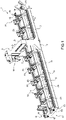
- number 1 indicates, as a whole, a work centre to process section bars 2 made of aluminium, light alloys, PVC or the like and having an elongated shape.
- the work centre 1 comprises an elongated base 3, which extends in a horizontal direction 4, is substantially U-shaped and is provided with two longitudinal guide members 5, which are parallel to the direction 4.
- the work centre 1 further has a gantry overhead crane 6 comprising a pair of vertical uprights 7, which are arranged on opposite sides of the base 3 in a horizontal direction 8, which is transverse to the direction 4, and are coupled to the base 3 in a known manner so as to make straight movements along the base 3 in the direction 4.
- a gantry overhead crane 6 comprising a pair of vertical uprights 7, which are arranged on opposite sides of the base 3 in a horizontal direction 8, which is transverse to the direction 4, and are coupled to the base 3 in a known manner so as to make straight movements along the base 3 in the direction 4.
- the two uprights 7 carry, connected to their free ends, a cross member 9, which extends above the base 3 in the direction 8 and supports a known operating head 10, which is coupled to the cross member 9 in a known manner so as to make straight movements along the cross member 9 in the direction 8.
- the head 10 is configured to process, for example mill and/or drill and/or cut, the section bars 2.
- the overhead crane 6 comprises one single upright 7.
- the work centre 1 further has a plurality of cross members 11, which extend between the longitudinal members 5 in the direction 8 and are coupled to the longitudinal members 5 in a sliding manner so as to be moved, by an operating device 12, along the longitudinal members 5 in the direction 4.
- the device 12 comprises two belt conveyors 13, which are parallel to one another, extend in the direction 4 and are mounted on opposite sides of the two longitudinal members 5 in the direction 8.
- Each conveyor 13 comprises a belt 14, which is wound in a ring shape around a pair of idler pulleys 15 mounted so as to rotate around respective rotation axes 16, which are parallel to one another and to a vertical direction 17, which is orthogonal to the directions 4 and 8.
- each cross member 11 is provided with two coupling devices 19 to couple the cross member 11 to the belts 14 and with two locking devices 20 to lock the cross member 11 on the longitudinal members 5.
- Each cross member 11 is further provided with a straight guide 21, which is fixed on an upper face of the cross member 11 parallel to the direction 8 and supports a clamping vice 22 comprising two holding jaws 23, 24 extending upwards from the cross member 11 in the direction 17.
- the vice 22 further comprises a support roller 25, which is mounted so as to rotate around a rotation axis 26 parallel to the direction 8 and defines, together with the rollers 25 of the other vices 22, a horizontal support surface P for a section bar 2.
- the roller 25 extends through the jaws 23, 24 in the direction 8, is substantially aligned with the guide 21 in the direction 17, is coupled in a rotary manner to the free ends of the output rods 27 (only one of them being shown in figures 2 and 3 ) of two actuator cylinders (not shown) obtained in the cross member 11 and is moved in the direction 17 by the actuator cylinders (not shown) depending on a height of the section bar 2.
- the jaw 23 is fixed to an end of the guide 21, whereas the jaw 24 is coupled to the guide 21 in a sliding manner so as to make straight movements in the direction 8 between a clamping position and a release position to clamp and release a section bar 2.
- the jaw 24 is moved along the guide 21 by an operating device 28 comprising a rack 29, which extends along the cross member 11 in the direction 8, is coupled to the cross member 11 in a sliding manner and is connected to an output rod 30 of an actuator cylinder 31 fixed to the cross member 11 parallel to the direction 8.
- the jaw 24 is locked on the rack 29 by means of a locking pin 32, whose disengagement from the rack 29 allows the jaw 24 to be selectively moved along the rack 29 in the direction 8.
- the jaws 23, 24 are provided with respective bumpers 33, which are made of an elastically deformable material, face one another, substantially have the shape of a parallelepiped and are coupled to the relative jaws 23, 24 in a sliding manner so as to be manually moved in the direction 17 during a set-up of the vice 22.
- Each cross member 11 further supports a vertical slide 34, which extends in the direction 8 and is coupled to the cross member 11 in a sliding manner so as to move in the direction 17 due to the thrust of an actuator cylinder 35.
- the slide 34 is provided with a straight guide 36, which is fixed on an upper face of the slide 34 parallel to the direction 8 and is engaged in a sliding manner by a plurality of support blocks 37, which are moveable along the guide 36 in the direction 8.
- the blocks 37 are delimited by respective flat upper faces 38, which are connected to a pneumatic suction device and define a second support surface P2 for the section bars 2.
- the blocks 37 are mounted on the slide 34 so as to be capable of being removed from it.
- the guides 21 and 36 are configured so as to allow the blocks 37 to move:
- the blocks 37 are moved by the slide 34 between a lowered position ( figure 2 ), in which the surface P2 is under the surface P1 and the blocks 37 disengage the section bar 2, a first lifted position ( figure 3 ), in which the surface P2 is substantially coplanar to the surface P1 and the blocks 37 support a central portion of the section bar 2 extending between the jaws 23 and 24, and a second lifted position ( figure 4 ), in which the surface P2 extends above the surface P1 and the blocks 37 disengage the section bar 2 from the rollers 25.
- the support blocks 37 correctly support the central portion of section bars 2 having a relatively great width in the direction 8 and, furthermore, allow the operating head 10 to correctly carry out the processing of said section bars 2.
- the guide 36 and the blocks 37 are eliminated and the slide 34 is delimited by a flat upper face, which defines the surface P2, is connected to the pneumatic suction device and is moved by the slide 34 between the aforesaid lowered position, first lifted position and second lifted position.
- the blocks 37 have different heights in the direction 17 and the surface P2 defined by the relative faces 38 has a step-like development in order to correctly support the section bars 2 with a corresponding shape.
Landscapes
- Engineering & Computer Science (AREA)
- Mechanical Engineering (AREA)
- Jigs For Machine Tools (AREA)
- Crystals, And After-Treatments Of Crystals (AREA)
- Forging (AREA)
- Adornments (AREA)
Claims (10)
- Centre de travail pour traiter des barres de section (2), en particulier fabriquées en aluminium, alliages légers, PVC ou analogues, comprenant une base (3) allongée s'étendant dans une première direction (4); une pluralité d'éléments de traverse (11), dont chacun est monté sur la base (3) parallèlement à une deuxième direction (8), qui est transversale à la première direction (4), supporte un étau de serrage (22) prévu avec deux mâchoires (23, 24) qui sont mobiles l'une par rapport à l'autre dans la deuxième direction (8) entre une position de serrage et une position de libération pour serrer et libérer au moins une barre de section (2), et supporte en outre des premiers moyens de support (25) définissant une première surface de support (P1) pour la barre de section (2) ; et un portique (6), qui s'étend au-dessus de la base (3) dans la deuxième direction (8) et est prévu avec une tête opérationnelle (10) pour traiter la barre de section (2) ; et caractérisé en ce que chaque élément de traverse (11) supporte en outre des deuxièmes moyens de support (34, 37), qui définissent une deuxième surface de support (P2) pour la barre de section (2) reliée à un dispositif d'aspiration pneumatique et sont mobiles dans une troisième direction (17), qui est orthogonale auxdites première et deuxième directions (4, 8), entre une position abaissée, dans laquelle la deuxième surface de support (P2) s'étend au-dessous de la première surface de support (P1), et une première position relevée.
- Centre de travail selon la revendication 1, dans lequel, lorsque les deuxièmes moyens de support (34, 37) sont agencés dans leur première position relevée, la deuxième surface de support (P2) est sensiblement coplanaire à la première surface de support (P1).
- Centre de travail selon la revendication 1 ou 2, dans lequel les deuxièmes moyens de support (34, 37) sont en outre mobiles dans une deuxième position relevée, dans laquelle la deuxième surface de support (P2) s'étend au-dessus de la première surface de support (P1).
- Centre de travail selon l'une quelconque des revendications précédentes, dans lequel les deuxièmes moyens de support (34, 37) comprennent une glissière (34), qui est mobile dans la troisième direction (17) et est délimitée par une face supérieure définissant la deuxième surface de support (P2).
- Centre de travail selon l'une quelconque des revendications 1 à 3, dans lequel les deuxièmes moyens de support (34, 37) comprennent une glissière (34), qui est mobile dans la troisième direction (17), et au moins un bloc de support (37), qui est mobile au long de la glissière (34) dans la deuxième direction (8) et est délimité par une face supérieure (38) définissant la deuxième surface de support (P2).
- Centre de travail selon la revendication 5, dans lequel la glissière (34) supporte une pluralité de blocs de support (37) répartis au long de la glissière (34) dans la deuxième direction (8).
- Centre de travail selon la revendication 5 ou 6, dans lequel les blocs de support (37) ont des hauteurs différentes dans la troisième direction (17) et la deuxième surface de support (P2) définie par les faces supérieures relatives (38) présente une conception étagée.
- Centre de travail selon l'une quelconque des revendications 5 à 7, dans lequel chaque bloc de support (37) est monté sur la glissière relative (34) de manière amovible.
- Centre de travail selon l'une quelconque des revendications 5 à 8, dans lequel l'élément de traverse (11) présente un premier dispositif de guidage (21), qui est mis en prise avec au moins l'une des mâchoires (23, 24) de l'étau de serrage (22) de manière coulissante, et dans lequel la glissière (34) présente un deuxième dispositif de guidage (36), qui est mis en prise de manière coulissante avec les blocs de support (37) ; les dispositifs de guidage (21, 36) étant configurés de manière à permettre aux blocs de support (37) de se déplacer entre les mâchoires (23, 24) et/ou au-delà d'au moins l'une des mâchoires (23, 24).
- Centre de travail selon l'une quelconque des revendications précédentes, dans lequel les premiers moyens de support (25) comprennent une barre de support s'étendant entre les mâchoires (23, 24).
Applications Claiming Priority (1)
| Application Number | Priority Date | Filing Date | Title |
|---|---|---|---|
| IT102020000003488A IT202000003488A1 (it) | 2020-02-20 | 2020-02-20 | Centro di lavoro per la lavorazione di profilati, in particolare di alluminio, leghe leggere, pvc o simili |
Publications (2)
| Publication Number | Publication Date |
|---|---|
| EP3868510A1 EP3868510A1 (fr) | 2021-08-25 |
| EP3868510B1 true EP3868510B1 (fr) | 2022-07-13 |
Family
ID=70738860
Family Applications (1)
| Application Number | Title | Priority Date | Filing Date |
|---|---|---|---|
| EP21158248.1A Active EP3868510B1 (fr) | 2020-02-20 | 2021-02-19 | Centre de travail pour traiter des barres de section, en particulier en aluminium, en alliages légers, en pvc ou analogues |
Country Status (2)
| Country | Link |
|---|---|
| EP (1) | EP3868510B1 (fr) |
| IT (1) | IT202000003488A1 (fr) |
Families Citing this family (2)
| Publication number | Priority date | Publication date | Assignee | Title |
|---|---|---|---|---|
| CN113579769A (zh) * | 2021-09-10 | 2021-11-02 | 沈佳慧 | 一种具备夹持可翻转功能的机械加工设备及翻转工艺 |
| CN115520648B (zh) * | 2022-09-27 | 2026-03-24 | 珠海格力智能装备有限公司 | 一种移载夹具 |
Family Cites Families (3)
| Publication number | Priority date | Publication date | Assignee | Title |
|---|---|---|---|---|
| DE4028446C1 (fr) * | 1990-09-07 | 1991-12-05 | Datron-Electronic Gmbh, 6109 Muehltal, De | |
| EP0562216A1 (fr) * | 1992-03-25 | 1993-09-29 | Fensterfabrik Albisrieden Ag | Machine-outil |
| IT201700056311A1 (it) * | 2017-05-24 | 2018-11-24 | F O M Ind S R L | Macchina per la lavorazione di profilati, in particolare di alluminio, leghe leggere, pvc o simili |
-
2020
- 2020-02-20 IT IT102020000003488A patent/IT202000003488A1/it unknown
-
2021
- 2021-02-19 EP EP21158248.1A patent/EP3868510B1/fr active Active
Also Published As
| Publication number | Publication date |
|---|---|
| EP3868510A1 (fr) | 2021-08-25 |
| IT202000003488A1 (it) | 2021-08-20 |
Similar Documents
| Publication | Publication Date | Title |
|---|---|---|
| EP3636386B1 (fr) | Centre d'usinage pour profiles en aluminium, pvc ou alliages legers | |
| EP3868510B1 (fr) | Centre de travail pour traiter des barres de section, en particulier en aluminium, en alliages légers, en pvc ou analogues | |
| US5353910A (en) | Shuttle vise assembly for a feed table apparatus | |
| EP3636384B1 (fr) | Centre d'usinage pour profilés en aluminium, alliages légers ou pvc. | |
| EP3950218B1 (fr) | Centre de travail pour traiter des barres de section, en particulier en aluminium, en alliages légers, en pvc ou analogues | |
| EP3254803B1 (fr) | Machine de traitement de barres de section | |
| US11745241B2 (en) | Bending machine for metal sheets with a tools' magazine | |
| EP3769907B1 (fr) | Machine pour traiter des barres de section en aluminium, alliages légers, pvc ou similaire | |
| EP3868511B1 (fr) | Centre de travail pour traiter des profilés, en particulier en aluminium, en alliages légers, en pvc ou analogues | |
| WO2017051047A1 (fr) | Dispositif d'empilage automatisé universel | |
| JP4615526B2 (ja) | 蒸気養生建築材料ブロックを分離する装置 | |
| EP2098344B2 (fr) | Procédé et machine pour usiner des composants de bois ou similaire | |
| CN102189437B (zh) | 托盘输送装置和托盘输送方法 | |
| EP3950217B1 (fr) | Procédé de configuration d'un poste de travail pour traiter des barres de section, fabriquées en particulier en aluminium, en alliages légers, en pvc ou analogues | |
| EP3636383B1 (fr) | Centre d'usinage pour profiles en aluminium, alliages legers ou pvc. | |
| US5363685A (en) | Transfer device in a press | |
| EP3167969B1 (fr) | Machine pour traiter des barres en aluminium, alliages légers, pvc ou analogues | |
| US5209341A (en) | Transfer device in a press | |
| CN217555129U (zh) | 一种进行物料传输的上下料装置 | |
| EP2210723A1 (fr) | Machine et méthode pour le travail du bois ou de materiaux similaires | |
| EP4275837A1 (fr) | Procédé et centre de travail pour traiter des barres profilées, en particulier en aluminium, alliages légers, pvc ou similaires | |
| CN113620049B (zh) | 一种用于产品抛光的输送装置 | |
| EP3928938B1 (fr) | Procédé et machine de forage pour forer dans des panneaux en bois ou similaires | |
| EP4112223A1 (fr) | Poste de travail pour traiter des barres de section, en particulier en aluminium, en alliages légers, en pvc ou analogues | |
| CN212766959U (zh) | 理瓶装置 |
Legal Events
| Date | Code | Title | Description |
|---|---|---|---|
| PUAI | Public reference made under article 153(3) epc to a published international application that has entered the european phase |
Free format text: ORIGINAL CODE: 0009012 |
|
| STAA | Information on the status of an ep patent application or granted ep patent |
Free format text: STATUS: THE APPLICATION HAS BEEN PUBLISHED |
|
| AK | Designated contracting states |
Kind code of ref document: A1 Designated state(s): AL AT BE BG CH CY CZ DE DK EE ES FI FR GB GR HR HU IE IS IT LI LT LU LV MC MK MT NL NO PL PT RO RS SE SI SK SM TR |
|
| STAA | Information on the status of an ep patent application or granted ep patent |
Free format text: STATUS: REQUEST FOR EXAMINATION WAS MADE |
|
| 17P | Request for examination filed |
Effective date: 20210906 |
|
| RBV | Designated contracting states (corrected) |
Designated state(s): AL AT BE BG CH CY CZ DE DK EE ES FI FR GB GR HR HU IE IS IT LI LT LU LV MC MK MT NL NO PL PT RO RS SE SI SK SM TR |
|
| GRAP | Despatch of communication of intention to grant a patent |
Free format text: ORIGINAL CODE: EPIDOSNIGR1 |
|
| STAA | Information on the status of an ep patent application or granted ep patent |
Free format text: STATUS: GRANT OF PATENT IS INTENDED |
|
| RIC1 | Information provided on ipc code assigned before grant |
Ipc: B23Q 3/08 20060101ALN20220112BHEP Ipc: B23Q 3/06 20060101AFI20220112BHEP |
|
| INTG | Intention to grant announced |
Effective date: 20220131 |
|
| GRAS | Grant fee paid |
Free format text: ORIGINAL CODE: EPIDOSNIGR3 |
|
| GRAA | (expected) grant |
Free format text: ORIGINAL CODE: 0009210 |
|
| STAA | Information on the status of an ep patent application or granted ep patent |
Free format text: STATUS: THE PATENT HAS BEEN GRANTED |
|
| AK | Designated contracting states |
Kind code of ref document: B1 Designated state(s): AL AT BE BG CH CY CZ DE DK EE ES FI FR GB GR HR HU IE IS IT LI LT LU LV MC MK MT NL NO PL PT RO RS SE SI SK SM TR |
|
| REG | Reference to a national code |
Ref country code: CH Ref legal event code: EP |
|
| REG | Reference to a national code |
Ref country code: DE Ref legal event code: R096 Ref document number: 602021000200 Country of ref document: DE |
|
| REG | Reference to a national code |
Ref country code: AT Ref legal event code: REF Ref document number: 1504019 Country of ref document: AT Kind code of ref document: T Effective date: 20220815 |
|
| REG | Reference to a national code |
Ref country code: IE Ref legal event code: FG4D |
|
| REG | Reference to a national code |
Ref country code: LT Ref legal event code: MG9D |
|
| REG | Reference to a national code |
Ref country code: NL Ref legal event code: MP Effective date: 20220713 |
|
| PG25 | Lapsed in a contracting state [announced via postgrant information from national office to epo] |
Ref country code: SE Free format text: LAPSE BECAUSE OF FAILURE TO SUBMIT A TRANSLATION OF THE DESCRIPTION OR TO PAY THE FEE WITHIN THE PRESCRIBED TIME-LIMIT Effective date: 20220713 Ref country code: RS Free format text: LAPSE BECAUSE OF FAILURE TO SUBMIT A TRANSLATION OF THE DESCRIPTION OR TO PAY THE FEE WITHIN THE PRESCRIBED TIME-LIMIT Effective date: 20220713 Ref country code: PT Free format text: LAPSE BECAUSE OF FAILURE TO SUBMIT A TRANSLATION OF THE DESCRIPTION OR TO PAY THE FEE WITHIN THE PRESCRIBED TIME-LIMIT Effective date: 20221114 Ref country code: NO Free format text: LAPSE BECAUSE OF FAILURE TO SUBMIT A TRANSLATION OF THE DESCRIPTION OR TO PAY THE FEE WITHIN THE PRESCRIBED TIME-LIMIT Effective date: 20221013 Ref country code: NL Free format text: LAPSE BECAUSE OF FAILURE TO SUBMIT A TRANSLATION OF THE DESCRIPTION OR TO PAY THE FEE WITHIN THE PRESCRIBED TIME-LIMIT Effective date: 20220713 Ref country code: LV Free format text: LAPSE BECAUSE OF FAILURE TO SUBMIT A TRANSLATION OF THE DESCRIPTION OR TO PAY THE FEE WITHIN THE PRESCRIBED TIME-LIMIT Effective date: 20220713 Ref country code: LT Free format text: LAPSE BECAUSE OF FAILURE TO SUBMIT A TRANSLATION OF THE DESCRIPTION OR TO PAY THE FEE WITHIN THE PRESCRIBED TIME-LIMIT Effective date: 20220713 Ref country code: FI Free format text: LAPSE BECAUSE OF FAILURE TO SUBMIT A TRANSLATION OF THE DESCRIPTION OR TO PAY THE FEE WITHIN THE PRESCRIBED TIME-LIMIT Effective date: 20220713 Ref country code: ES Free format text: LAPSE BECAUSE OF FAILURE TO SUBMIT A TRANSLATION OF THE DESCRIPTION OR TO PAY THE FEE WITHIN THE PRESCRIBED TIME-LIMIT Effective date: 20220713 |
|
| REG | Reference to a national code |
Ref country code: AT Ref legal event code: MK05 Ref document number: 1504019 Country of ref document: AT Kind code of ref document: T Effective date: 20220713 |
|
| PG25 | Lapsed in a contracting state [announced via postgrant information from national office to epo] |
Ref country code: PL Free format text: LAPSE BECAUSE OF FAILURE TO SUBMIT A TRANSLATION OF THE DESCRIPTION OR TO PAY THE FEE WITHIN THE PRESCRIBED TIME-LIMIT Effective date: 20220713 Ref country code: IS Free format text: LAPSE BECAUSE OF FAILURE TO SUBMIT A TRANSLATION OF THE DESCRIPTION OR TO PAY THE FEE WITHIN THE PRESCRIBED TIME-LIMIT Effective date: 20221113 Ref country code: HR Free format text: LAPSE BECAUSE OF FAILURE TO SUBMIT A TRANSLATION OF THE DESCRIPTION OR TO PAY THE FEE WITHIN THE PRESCRIBED TIME-LIMIT Effective date: 20220713 Ref country code: GR Free format text: LAPSE BECAUSE OF FAILURE TO SUBMIT A TRANSLATION OF THE DESCRIPTION OR TO PAY THE FEE WITHIN THE PRESCRIBED TIME-LIMIT Effective date: 20221014 |
|
| REG | Reference to a national code |
Ref country code: DE Ref legal event code: R097 Ref document number: 602021000200 Country of ref document: DE |
|
| PG25 | Lapsed in a contracting state [announced via postgrant information from national office to epo] |
Ref country code: SM Free format text: LAPSE BECAUSE OF FAILURE TO SUBMIT A TRANSLATION OF THE DESCRIPTION OR TO PAY THE FEE WITHIN THE PRESCRIBED TIME-LIMIT Effective date: 20220713 Ref country code: RO Free format text: LAPSE BECAUSE OF FAILURE TO SUBMIT A TRANSLATION OF THE DESCRIPTION OR TO PAY THE FEE WITHIN THE PRESCRIBED TIME-LIMIT Effective date: 20220713 Ref country code: DK Free format text: LAPSE BECAUSE OF FAILURE TO SUBMIT A TRANSLATION OF THE DESCRIPTION OR TO PAY THE FEE WITHIN THE PRESCRIBED TIME-LIMIT Effective date: 20220713 Ref country code: CZ Free format text: LAPSE BECAUSE OF FAILURE TO SUBMIT A TRANSLATION OF THE DESCRIPTION OR TO PAY THE FEE WITHIN THE PRESCRIBED TIME-LIMIT Effective date: 20220713 Ref country code: AT Free format text: LAPSE BECAUSE OF FAILURE TO SUBMIT A TRANSLATION OF THE DESCRIPTION OR TO PAY THE FEE WITHIN THE PRESCRIBED TIME-LIMIT Effective date: 20220713 |
|
| PLBE | No opposition filed within time limit |
Free format text: ORIGINAL CODE: 0009261 |
|
| STAA | Information on the status of an ep patent application or granted ep patent |
Free format text: STATUS: NO OPPOSITION FILED WITHIN TIME LIMIT |
|
| PG25 | Lapsed in a contracting state [announced via postgrant information from national office to epo] |
Ref country code: SK Free format text: LAPSE BECAUSE OF FAILURE TO SUBMIT A TRANSLATION OF THE DESCRIPTION OR TO PAY THE FEE WITHIN THE PRESCRIBED TIME-LIMIT Effective date: 20220713 Ref country code: EE Free format text: LAPSE BECAUSE OF FAILURE TO SUBMIT A TRANSLATION OF THE DESCRIPTION OR TO PAY THE FEE WITHIN THE PRESCRIBED TIME-LIMIT Effective date: 20220713 |
|
| 26N | No opposition filed |
Effective date: 20230414 |
|
| PG25 | Lapsed in a contracting state [announced via postgrant information from national office to epo] |
Ref country code: AL Free format text: LAPSE BECAUSE OF FAILURE TO SUBMIT A TRANSLATION OF THE DESCRIPTION OR TO PAY THE FEE WITHIN THE PRESCRIBED TIME-LIMIT Effective date: 20220713 |
|
| PG25 | Lapsed in a contracting state [announced via postgrant information from national office to epo] |
Ref country code: SI Free format text: LAPSE BECAUSE OF FAILURE TO SUBMIT A TRANSLATION OF THE DESCRIPTION OR TO PAY THE FEE WITHIN THE PRESCRIBED TIME-LIMIT Effective date: 20220713 |
|
| PG25 | Lapsed in a contracting state [announced via postgrant information from national office to epo] |
Ref country code: MC Free format text: LAPSE BECAUSE OF FAILURE TO SUBMIT A TRANSLATION OF THE DESCRIPTION OR TO PAY THE FEE WITHIN THE PRESCRIBED TIME-LIMIT Effective date: 20220713 |
|
| REG | Reference to a national code |
Ref country code: BE Ref legal event code: MM Effective date: 20230228 |
|
| P01 | Opt-out of the competence of the unified patent court (upc) registered |
Effective date: 20230915 |
|
| PG25 | Lapsed in a contracting state [announced via postgrant information from national office to epo] |
Ref country code: LU Free format text: LAPSE BECAUSE OF NON-PAYMENT OF DUE FEES Effective date: 20230219 |
|
| REG | Reference to a national code |
Ref country code: IE Ref legal event code: MM4A |
|
| PG25 | Lapsed in a contracting state [announced via postgrant information from national office to epo] |
Ref country code: IT Free format text: LAPSE BECAUSE OF FAILURE TO SUBMIT A TRANSLATION OF THE DESCRIPTION OR TO PAY THE FEE WITHIN THE PRESCRIBED TIME-LIMIT Effective date: 20220713 Ref country code: IE Free format text: LAPSE BECAUSE OF NON-PAYMENT OF DUE FEES Effective date: 20230219 |
|
| PG25 | Lapsed in a contracting state [announced via postgrant information from national office to epo] |
Ref country code: BE Free format text: LAPSE BECAUSE OF NON-PAYMENT OF DUE FEES Effective date: 20230228 |
|
| REG | Reference to a national code |
Ref country code: CH Ref legal event code: PL |
|
| PG25 | Lapsed in a contracting state [announced via postgrant information from national office to epo] |
Ref country code: CH Free format text: LAPSE BECAUSE OF NON-PAYMENT OF DUE FEES Effective date: 20240229 |
|
| PG25 | Lapsed in a contracting state [announced via postgrant information from national office to epo] |
Ref country code: CH Free format text: LAPSE BECAUSE OF NON-PAYMENT OF DUE FEES Effective date: 20240229 |
|
| PG25 | Lapsed in a contracting state [announced via postgrant information from national office to epo] |
Ref country code: BG Free format text: LAPSE BECAUSE OF FAILURE TO SUBMIT A TRANSLATION OF THE DESCRIPTION OR TO PAY THE FEE WITHIN THE PRESCRIBED TIME-LIMIT Effective date: 20220713 |
|
| PG25 | Lapsed in a contracting state [announced via postgrant information from national office to epo] |
Ref country code: BG Free format text: LAPSE BECAUSE OF FAILURE TO SUBMIT A TRANSLATION OF THE DESCRIPTION OR TO PAY THE FEE WITHIN THE PRESCRIBED TIME-LIMIT Effective date: 20220713 |
|
| PG25 | Lapsed in a contracting state [announced via postgrant information from national office to epo] |
Ref country code: CY Free format text: LAPSE BECAUSE OF FAILURE TO SUBMIT A TRANSLATION OF THE DESCRIPTION OR TO PAY THE FEE WITHIN THE PRESCRIBED TIME-LIMIT; INVALID AB INITIO Effective date: 20210219 |
|
| PG25 | Lapsed in a contracting state [announced via postgrant information from national office to epo] |
Ref country code: HU Free format text: LAPSE BECAUSE OF FAILURE TO SUBMIT A TRANSLATION OF THE DESCRIPTION OR TO PAY THE FEE WITHIN THE PRESCRIBED TIME-LIMIT; INVALID AB INITIO Effective date: 20210219 |
|
| GBPC | Gb: european patent ceased through non-payment of renewal fee |
Effective date: 20250219 |
|
| PG25 | Lapsed in a contracting state [announced via postgrant information from national office to epo] |
Ref country code: TR Free format text: LAPSE BECAUSE OF FAILURE TO SUBMIT A TRANSLATION OF THE DESCRIPTION OR TO PAY THE FEE WITHIN THE PRESCRIBED TIME-LIMIT Effective date: 20220713 |
|
| PG25 | Lapsed in a contracting state [announced via postgrant information from national office to epo] |
Ref country code: GB Free format text: LAPSE BECAUSE OF NON-PAYMENT OF DUE FEES Effective date: 20250219 |
|
| PGFP | Annual fee paid to national office [announced via postgrant information from national office to epo] |
Ref country code: DE Payment date: 20260220 Year of fee payment: 6 |
|
| PGFP | Annual fee paid to national office [announced via postgrant information from national office to epo] |
Ref country code: FR Payment date: 20260227 Year of fee payment: 6 |