EP3868636A1 - Trottinette - Google Patents
Trottinette Download PDFInfo
- Publication number
- EP3868636A1 EP3868636A1 EP21158438.8A EP21158438A EP3868636A1 EP 3868636 A1 EP3868636 A1 EP 3868636A1 EP 21158438 A EP21158438 A EP 21158438A EP 3868636 A1 EP3868636 A1 EP 3868636A1
- Authority
- EP
- European Patent Office
- Prior art keywords
- handlebar
- chassis
- section
- locking element
- kick scooter
- Prior art date
- Legal status (The legal status is an assumption and is not a legal conclusion. Google has not performed a legal analysis and makes no representation as to the accuracy of the status listed.)
- Granted
Links
Images


Classifications
-
- B—PERFORMING OPERATIONS; TRANSPORTING
- B62—LAND VEHICLES FOR TRAVELLING OTHERWISE THAN ON RAILS
- B62K—CYCLES; CYCLE FRAMES; CYCLE STEERING DEVICES; RIDER-OPERATED TERMINAL CONTROLS SPECIALLY ADAPTED FOR CYCLES; CYCLE AXLE SUSPENSIONS; CYCLE SIDE-CARS, FORECARS, OR THE LIKE
- B62K3/00—Bicycles
- B62K3/002—Bicycles without a seat, i.e. the rider operating the vehicle in a standing position, e.g. non-motorized scooters; non-motorized scooters with skis or runners
-
- B—PERFORMING OPERATIONS; TRANSPORTING
- B62—LAND VEHICLES FOR TRAVELLING OTHERWISE THAN ON RAILS
- B62K—CYCLES; CYCLE FRAMES; CYCLE STEERING DEVICES; RIDER-OPERATED TERMINAL CONTROLS SPECIALLY ADAPTED FOR CYCLES; CYCLE AXLE SUSPENSIONS; CYCLE SIDE-CARS, FORECARS, OR THE LIKE
- B62K15/00—Collapsible or foldable cycles
Definitions
- the invention relates to a scooter.
- Such scooters are known in various forms and designs.
- the DE 10 2012 204 909 A1 discloses a three-wheeled scooter, the handlebar of which is retractable so that the scooter can be more easily stowed and transported.
- the EP 3 156 311 A1 discloses a scooter with three wheels, the handlebar of which can be installed in two different positions, one position being used for storage and transport.
- the WO 2017 190 173 A1 reveals numerous scooter variants with foldable handlebars.
- Disadvantages of known scooters with foldable handlebars include the often difficult operation and the ability to remove the handlebars, which can lead to their loss.
- the object of the present invention is to overcome the disadvantages of the prior art.
- a scooter according to the present invention comprises a chassis, at least one front wheel and at least one rear wheel and a handlebar.
- the handlebar is positively connected to the chassis.
- a section of the handlebar together with a section of the chassis or with a section attached to the chassis, forms a swivel joint which allows the handlebar to be rotated relative to the chassis so that the handlebars can be moved back and forth between a ready-to-drive position and a transport position can.
- the above-described form fit between the handlebar and the chassis is also maintained during the rotation mentioned above, since both parts can only be rotated relative to one another, but cannot be separated without dismantling.
- the form-fitting connection between the handlebar and the chassis is preferably such that the only degree of freedom of movement is rotation about a predetermined axis of rotation. Provides a If the screw or the like described in more detail below provides the axis of rotation, its longitudinal axis is at the same time the axis of rotation.
- the chassis or the section attached to the chassis or the section of the handlebar comprises a locking element which can be moved back and forth between a retracted and an extended position. In the retracted position, the locking element does not protrude into the joint gap in order to allow rotation of the handlebar relative to the chassis. In the extended position, the locking element protrudes into the joint gap, so that the chassis or the section attached to the chassis interacts with the section of the handlebar in order to block the rotation of the handlebar relative to the chassis. This interaction is preferably brought about, as described above, by the locking element which is arranged in one of the aforementioned sections.
- the locking element receptacles which are described in more detail below, are correspondingly received in the opposite or corresponding section.
- the chassis or the handlebar is connected to an actuation arrangement for the locking element.
- the actuation arrangement comprises an actuation element which can be actuated by a user.
- the actuation arrangement is designed to move the locking element from the extended into the retracted position when the actuating element is actuated by a user.
- the chassis is preferably the chassis of the scooter to which the essential elements are attached, for example the wheels, possibly a step, etc.
- a part of the chassis can also be designed as a step so that there is no need for a separate step.
- other attachments and superstructures - based on the structure of common motor vehicles For example, the body that is attached to the chassis / chassis - can be set on the chassis of the scooter.
- the handlebar In the ready-to-drive position and preferably also in the transport position, the handlebar can preferably only be moved, i.e. rotated, relative to the chassis after the actuation element has been actuated.
- connection between the handlebar and the chassis can be direct or indirect.
- a part of the swivel joint on the chassis side can be provided on the one hand by a section of the chassis itself.
- the chassis-side part of the swivel joint can be connected to the chassis by a section of a body fastened to the chassis or by another section fastened to the chassis.
- the last-mentioned section can preferably serve exclusively to form the swivel joint.
- An axis of rotation of the swivel joint which specifies the possible rotation of the handlebar relative to the chassis, can be formed from a screw or a bolt which penetrates both part of the handlebar and part of the chassis and connects the two with one another in a form-fitting manner. This positive connection ensures that the handlebar and chassis cannot be easily dismantled, but allows both parts to rotate relative to one another.
- a section of the handlebar can be inserted into an undercut opening provided on the chassis. In this way, both parts are positively connected to one another without the need for a screw or bolt.
- the ball bearings or the like described below can also be present in such a variant.
- the handlebar in particular the joint-forming section, for example the flange-like end section, comprises a bolt-like projection or, for example, an integrally formed bolt.
- the joint-forming section of the chassis can include a corresponding hole or blind hole for receiving the bolt, so that both together form a swivel joint.
- the hole or blind hole can also be arranged on the handlebar and the molded bolt or the like can be arranged accordingly on the chassis.
- the aforementioned section of the handlebar which provides part of the swivel joint, is preferably a flange-like end section. It could also be referred to as a "joint-forming section", although it does not necessarily, but preferably, have to be flange-like, i.e. widened at the bottom.
- the scooter can include exactly one locking element.
- the scooter can also include exactly two locking elements, which is preferred.
- the scooter can also comprise three or more locking elements. Regardless of whether the locking element is used in the singular or plural in the context of the present invention, both possibilities can always be considered. Although two locking elements are preferred, exactly one locking element, exactly three locking elements or more locking elements can also be thought of.
- the interaction between the section of the chassis or the section attached to the chassis on the one hand and the section of the handlebar on the other hand can be non-positive or positive.
- this interaction is preferably achieved by the in one of the sections located locking element provided.
- a frictional connection for example at least one locking element protruding from a section into the joint gap can be pressed against the opposite section in order to generate the frictional connection.
- the interaction preferably takes place in a form-fitting manner, the at least one locking element engaging, for example, in a locking element receptacle described in more detail below.
- connection between the chassis or the handlebar on the one hand and the actuation arrangement on the other hand also includes exemplary embodiments in which part of the chassis or part of the handlebar is designed as an actuation arrangement.
- the invention is not limited to embodiments according to which the actuation arrangement is formed from at least one separate component which is then attached to the chassis or to the handlebar.
- the actuating element can be a push button, a lever or the like.
- the portion of the handlebar can be a flange-like end portion.
- the “section” of the handlebar in the following always designates a joint-forming section, which is preferably (but not necessarily) designed as a flange-like end section.
- the scooter can comprise a step surface, the section of the chassis or the section attached to the chassis being inclined at an angle of 40 ° to 50 ° to the step surface.
- the section of the handlebar is preferably also inclined by 40 ° to 50 ° relative to an imaginary longitudinal axis of the handlebar, so that the handlebars are mounted in the ready-to-drive position relative to the tread at an angle of 80 ° to 100 °, preferably about 90 ° can.
- the above-described inclinations each preferably relate to the surfaces or surface sections of the two sections which together form the joint gap.
- section of the chassis in the following always refers to a joint-forming section which is either part of the chassis or is attached to the chassis.
- the scooter can be set up in such a way that the swivel joint allows the handlebar to be rotated by at least 180 °.
- a screw or a bolt which is described in more detail below, is preferably used as the axis of rotation.
- the scooter can comprise a locking element receptacle for receiving the locking element. Furthermore, the scooter can also comprise a screw or bolt receptacle for receiving a screw or a bolt, the screw or the bolt defining an axis of rotation of the swivel joint.
- a locking element receptacle for receiving the locking element.
- the scooter can also comprise a screw or bolt receptacle for receiving a screw or a bolt, the screw or the bolt defining an axis of rotation of the swivel joint.
- exactly one, exactly two or three or more locking element receptacles can be thought of.
- the at least one locking element receptacle can be located both in the section of the chassis or in the section fastened to the chassis and in the section of the handlebar.
- a distance between the locking element receptacle and the screw or bolt receptacle can be at least 30 mm. This distance is preferably measured between the respective geometric centers of the locking element receptacle and screw or bolt receptacle.
- the surfaces forming the joint gap can have a diameter of at least 80 mm. If the surfaces are not round, which is possible, this applies to the smallest diameter.
- the scooter preferably comprises exactly two wheels at the front and exactly one wheel at the rear.
- the handlebar is preferably in the ready-to-drive position, too by means of the locking elements - rigidly connected to the chassis as long as the actuating element is not actuated.
- the locking elements can be designed as bolts, pins or the like.
- the shape of the locking element receptacles is correspondingly complementary and can be made in the manner of a blind hole.
- the scooter comprises exactly two locking elements. In this way a desired redundancy is given. If a locking element becomes inoperable, the second locking element continues to perform the locking function. Preferably, both locking elements are moved by exactly one actuation arrangement in order to allow a rotation of the handlebar relative to the chassis. In spite of the redundancy described above in the event that a locking element is destroyed, both locking elements can thus be unlocked at the same time with little effort in order to allow the handlebar to be turned.
- the Handlebar can be arranged in the ready-to-drive position in a comfortable 90 ° position relative to the step surface.
- the step surface and the handlebar are then arranged essentially parallel to one another and form an angle of 0 °.
- other angles can also be thought of, but angles of 40 ° to 50 ° are preferred in each case.
- the locking elements preferably have only one degree of freedom of translation.
- the permitted direction of movement of the locking elements is preferably oriented orthogonally to the joint gap or to the joint-forming sections of the handlebar and chassis.
- the locking element receptacles and / or the locking elements can have a radius or circumference that changes along their longitudinal direction.
- cone-shaped configurations can be thought of, for example.
- the blocking element receptacle which essentially consists of an opening in one of the above-described surfaces (sections) and a hole or blind hole, can have a larger circumference at the opening than, for example, at the bottom of the blind hole.
- a free tip of the locking element which first moves into the locking element receptacle, can have a smaller circumference than the opposite end of the locking element.
- a simple locking in the ready-to-drive and in the transport position can be achieved.
- a simple and safe centering in the above-described positions can thus be achieved, which does not cause any trouble for the user.
- chassis and the handlebar are positively connected to one another prevents the two parts from being accidentally separated from one another. This is ensured by the already described captive connection by means of a screw or the like, which allows only a single degree of freedom of movement for rotation about the axis of rotation of the swivel joint, but does not allow any other rotational or translational degrees of freedom. Especially when using ball bearings or the like are also made possible by small gap dimensions and precise and play-free assembly.
- connection via a screw or the like as the axis of rotation also makes it possible to simply consist of two essentially planar surfaces or surface sections of the chassis together with the elements required to block the rotational movement, ie the at least one blocking element and the corresponding at least one blocking element receptacle on the one hand and the handlebar on the other hand.
- These surface sections are preferably arranged at the angles already described above to the step surface or to the longitudinal direction of the handlebar.
- one of the surface sections can of course also have a depression or be designed as a depression, the corresponding surface section engaging in this depression.
- the (joint-forming) section of the chassis can have a (preferably circular) recess into which the (joint-forming) section of the handlebar is inserted and then screwed. This recess then acts as a guide to increase stability.
- the surface sections described above preferably do not slide directly on one another. Instead, at least one ball bearing or at least one other suitable bearing is provided in the area of the joint gap in order to facilitate the sliding of both surface sections and thus the rotation of the handlebar relative to the chassis.
- the surface sections themselves can, however, be made of a material which allows low-friction sliding.
- the flange-like end section has a diameter of at least 50 Millimeters, preferably at least 60 millimeters, even more preferably at least 70 millimeters and further preferably at least 80 millimeters.
- a distance between the screw or the like forming the swivel joint on the one hand and the locking elements or locking element receptacles on the other side is as large as possible and is preferably at least 20 millimeters, preferably at least 25 millimeters. The distance is preferably defined here by the geometric centers of the screw or the like and the locking element receptacle.
- the handlebar is preferably formed from the flange-like end section and a tube, both parts being connected to one another by a connecting element such as a screw or a bolt or a rivet or a spring pin. Both parts are preferably connected in such a way that they cannot move relative to one another.
- the tube can comprise a seat shell or a seat case.
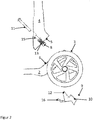
- a section of the scooter 1 is shown in each of the figures.
- a chassis 2 and a handlebar 4 can be seen.
- front wheels 3 or at least one front wheel 3 are also shown.
- the handlebar 4 comprises a joint-forming section 5 and the chassis 2 comprises a joint-forming section 6.
- the joint-forming section 5 of the handlebar 4 is located at a flange-like end section 17 which is connected to a tube 18. Between these sections 5, 6 is a joint gap 7, which is in the Figures 1 and 4th is recognizable.
- a blocking element 8 can also be seen.
- An actuation arrangement 9 comprises an actuation element 10, a pivot point 12 and an extension 16. Furthermore, a screw 11 and a spring 13 can be seen.
- two Locking element receptacles 14 can be seen as well as a screw receptacle 15.
- part of a step surface 21 is indicated.
- Ball bearings or the like are preferably provided in the area of the screw receptacles 15 in order to allow the steering rod 4 to rotate about the screw 11 as the axis of rotation when the actuating element 10 is actuated.
- a locking element 8 is provided, which is pretensioned by a spring 13 in order to engage in the locking element receptacle 14 after assembly.
- the kick scooter 1 shown comprises two locking elements 8 with two corresponding locking element receptacles 14.
- the actuating arrangement 9 accordingly comprises two extensions 16, which, however, in the side views of the Figures 1 , 2 and 4th are not recognizable. Each extension 16 moves a locking element 8.
- the screw 11 is mounted centrally between the two locking elements 8.
- the user can drive with the scooter 1, the handlebar 4 is in the ready-to-drive position.
- An angle between the step surface 21 and the tube 18 or between the step surface 21 and an imaginary longitudinal axis of the handlebar 4 is approximately 90 °.
- the handlebar 4 is immovable with respect to the chassis 2 as long as the user does not actuate the actuating element 10.
- the scooter 1, which preferably comprises two front wheels 3 and a rear wheel (not shown), can be steered transversely to the direction of travel by tilting the handlebar 4.
- a scooter 1 controllable in this way, in particular the steering mechanism, is known.
- the actuation element 10 is pressed and the above-described pivoting about the pivot point 12 takes place against the pretensioning force of a second spring 22.
- the pretensioning force of the second spring 22 must be overcome.
- the locking elements 8 are moved out or pushed out of the locking element receptacles 14 against the prestressing force of the spring 13.
- the spring 13 acts on the locking elements 8 with a force which acts against the direction of the arrow 23.
- a stop (not shown) or the like preferably restricts the maximum rotation of the actuation arrangement 9 in such a way that the extensions 16 do not protrude into the joint gap 7 when the actuation element 10 has been pushed downward at the maximum in the direction of arrow 20.
- the maximum rotation of the actuation arrangement 9 is designed in such a way that the locking elements 8 have been pushed essentially completely out of the joint gap 7 in the direction of an arrow 23 by the extensions 16.
- the joint gap 7 is preferably very narrow.
- the extensions 16 terminate substantially flat with the surface of the joint-forming section 6 of the chassis 2 that forms the joint gap 7, and the locking elements 8 terminate even with the surface of the joint-forming section 5 of the handlebar 4 forming the joint gap 7, if the actuating element 10 was pushed in maximally in the direction of the arrow 20.
- the handlebar 4 can be rotated relative to the chassis 2, the screw 11 functioning as the axis of rotation.
- the user can push in the actuating element 10 in the direction of the arrow 20, which leads to the swiveling of the actuating arrangement 9 along the arrow 19, the extensions 16 pushing the locking elements 8 out of the locking element receptacles 14 in the direction of the arrow 23.
- the locking elements 8 are removed from engagement with the locking element receptacles 14 and release the joint gap 7, so that rotation the handlebar 4 about the axis of rotation defined by the screw 11 is possible.
- a connecting element 24 can also be seen, which can be a screw, a spring pin or the like.
- This connecting element 24 holds the flange-like end section 17 and the tube 18 together so that they cannot move relative to one another.
- This connecting element 24 also allows the tube 18 to be exchanged for a differently constructed tube (not shown).
- the tube 18 can end at the upper end (not shown) in a conventional knob with which the scooter 1 is controlled by a lateral inclination.
- an alternative tube comprising both a control knob or the like and a seat shell or a seat case for the toddler can be mounted.
- the connecting element 24 is loosened and removed, the tube 18 is removed and the alternative tube (not shown) is mounted.
- the alternative pipe is then fastened to the flange-like end section 17 with the aid of the connecting element 24. With the flange-like end section 17, this alternative tube naturally also forms a handlebar 4 within the meaning of the present invention.
- knob instead of the knob, other steering devices can also be thought of in all exemplary embodiments, for example a handlebar running transversely to the tube 18 with two handles (not shown), as is customary on bicycles.
- the screw 11 is preferably screwed into a thread (not shown) in the chassis 2.
- the thread can be located in the screw receptacle 15. It is of course also conceivable to insert the screw 11 from below so that the screw head does not rest on the flange-like end section 17 but on the chassis 2 and is screwed into a thread within the flange-like end section 17.
- the axis of rotation and the form-fitting connection of the handlebar 4 and chassis 2 can also be provided in other ways.
- a bolt or the like can also be used.
- the joint-forming sections 5, 6 can be connected to one another by suitable undercuts, for example inserted into one another, that the undercuts ensure the form-fitting connection and the axis of rotation results from the design of both sections 5, 6 itself, without any Bolts or the like as a physically available axis of rotation.
- the actuating arrangement 9 preferably comprises two extensions 16. Alternatives are conceivable.
- the number of extensions 16 preferably corresponds to the number of locking elements 8. Variants of the scooter 1 are also conceivable which include exactly one locking element 8 or three or more locking elements 8.
- the actuation arrangement 9 preferably has exactly one actuation element 10, so that simple operation, in particular by simply pressing a button, is always possible.
- the actuation arrangement 9 can have exactly one pivot point 12 or two pivot points 12 or more Include pivot points 12, and at least one axis of rotation can also be envisaged.
- exactly two second springs 22, exactly one second spring 22 or more than two second springs 22 can be envisaged.
- locking elements 8 are fixed to the handlebar 4 in the embodiment shown, while the locking element receptacles 14 are located in the chassis 2.
- the reverse arrangement is also conceivable, so that the locking elements 8 are attached to the chassis 2 and the locking element receptacles 14 are provided on the handlebar 4, in particular on the flange-like end section 17.
- the actuation arrangement 9 is arranged on the same side, namely on the chassis 2, relative to the joint gap 7. Actuating the actuating element 10 causes the extensions 16 to push the locking elements 8 out of the chassis 2 or the locking element receptacles 14 provided there in the direction of the handlebar 4, ie in the direction of the other side of the joint gap 7. This movement takes place in the direction of an arrow 23.
- the actuating arrangement 9 would ensure that the locking elements 8 are moved in the opposite direction of the arrow 23 when the actuating element 10 is actuated.
- This can be done by a suitable alternative arrangement of the pivot point 12, preferably in conjunction with a modified configuration of the actuation arrangement be achieved by yourself.
- the locking elements 8 would, of course, be sensibly fixed on the chassis 2.
- the locking elements 8 Upon actuation of the actuating element 10, the locking elements 8 would thus be moved into the chassis 2 or away from the flange-like end section 17 in the opposite direction of the arrow 23 in the alternative embodiment described above.
- the locking element (s) 8 can either be arranged in the handlebar 4, there in particular - if present - in the flange-like section 17, or alternatively in the chassis 2.
- the arrangement of the blocking element receptacles 14 on the opposite side of the joint gap 7 is predetermined by the arrangement of the blocking elements 8, but the arrangement of the actuating arrangement 9 is not.
- the handlebar 4 can be made in one piece.
- the handlebar 4 can comprise a tube 18 and a flange-like end section 17 as separate but firmly connected components.
- the flange-like end section 17 can also be made smaller than shown in the figures.
- the one is flange-like
- the end section is present and has a diameter of preferably over 70 millimeters, preferably 70 to 90 millimeters.
- the actuating element 10 is preferably a push button as in FIG Figure 3 evident. However, other actuating elements can also be thought of.
- the actuating element 10 is preferably as in FIG Figure 3 shown attached to a front of the chassis 2, so that accidental actuation is excluded while driving. However, other arrangements are conceivable.
- the actuating element 10 preferably ends flush with a frame surrounding it or with a surface of the chassis 2 surrounding it or is even sunk a little into it, which also makes it difficult to actuate it inadvertently. Alternatively, the actuating element 10 can also protrude a little beyond the surface of the chassis 2.
- the actuation arrangement 9 can be in one piece or in several pieces.
- the actuation arrangement 9 comprises the actuation element 10, the pivot point 12 and the extensions 16. These three sections 10, 12, 16 do not necessarily have to be designed in one piece. Multi-piece embodiments can be thought of, with the individual parts also being able to be suspended from several pivot points or axes of rotation or be supported in a different manner in order to allow more complex kinematics.
- Ball bearings or the like or, alternatively, other friction-reducing components can be provided anywhere within the joint-forming sections 5, 6 and in particular within the surface sections 25.
- the surface section of the flange-like end section 17 corresponding to the surface section 25 or lying opposite the joint gap 7 is shown in FIG Figure 3 not recognizable due to the chosen perspective).
- the surface sections 25 themselves can also be made of low-friction material.
Landscapes
- Engineering & Computer Science (AREA)
- Mechanical Engineering (AREA)
- Steering Devices For Bicycles And Motorcycles (AREA)
Applications Claiming Priority (1)
| Application Number | Priority Date | Filing Date | Title |
|---|---|---|---|
| DE102020104667.7A DE102020104667A1 (de) | 2020-02-21 | 2020-02-21 | Tretroller |
Publications (2)
| Publication Number | Publication Date |
|---|---|
| EP3868636A1 true EP3868636A1 (fr) | 2021-08-25 |
| EP3868636B1 EP3868636B1 (fr) | 2024-04-03 |
Family
ID=74673097
Family Applications (1)
| Application Number | Title | Priority Date | Filing Date |
|---|---|---|---|
| EP21158438.8A Active EP3868636B1 (fr) | 2020-02-21 | 2021-02-22 | Trotinette |
Country Status (2)
| Country | Link |
|---|---|
| EP (1) | EP3868636B1 (fr) |
| DE (1) | DE102020104667A1 (fr) |
Cited By (1)
| Publication number | Priority date | Publication date | Assignee | Title |
|---|---|---|---|---|
| US11440608B2 (en) * | 2018-11-19 | 2022-09-13 | Id Development Limited | Kick scooter |
Citations (5)
| Publication number | Priority date | Publication date | Assignee | Title |
|---|---|---|---|---|
| DE102012204909A1 (de) | 2012-03-27 | 2013-10-02 | Bayerische Motoren Werke Aktiengesellschaft | Tretroller mit mindestens zwei Rädern |
| EP3156311A1 (fr) | 2015-10-16 | 2017-04-19 | ID Development Limited | Engin a roues, notamment pour enfants |
| WO2017190173A1 (fr) | 2016-05-06 | 2017-11-09 | Scoot & Ride Gmbh | Articulation |
| DE202018100928U1 (de) * | 2018-02-20 | 2018-04-23 | Dan Gong | Kinderroller |
| US20190241232A1 (en) * | 2016-06-15 | 2019-08-08 | Yvolve Sports Ltd. | Pivot joint and vehicles that employ a pivot joint |
Family Cites Families (1)
| Publication number | Priority date | Publication date | Assignee | Title |
|---|---|---|---|---|
| CN105730577B (zh) | 2016-02-03 | 2018-09-25 | 朱慧敏 | 一种二合一两用新型童车 |
-
2020
- 2020-02-21 DE DE102020104667.7A patent/DE102020104667A1/de not_active Withdrawn
-
2021
- 2021-02-22 EP EP21158438.8A patent/EP3868636B1/fr active Active
Patent Citations (5)
| Publication number | Priority date | Publication date | Assignee | Title |
|---|---|---|---|---|
| DE102012204909A1 (de) | 2012-03-27 | 2013-10-02 | Bayerische Motoren Werke Aktiengesellschaft | Tretroller mit mindestens zwei Rädern |
| EP3156311A1 (fr) | 2015-10-16 | 2017-04-19 | ID Development Limited | Engin a roues, notamment pour enfants |
| WO2017190173A1 (fr) | 2016-05-06 | 2017-11-09 | Scoot & Ride Gmbh | Articulation |
| US20190241232A1 (en) * | 2016-06-15 | 2019-08-08 | Yvolve Sports Ltd. | Pivot joint and vehicles that employ a pivot joint |
| DE202018100928U1 (de) * | 2018-02-20 | 2018-04-23 | Dan Gong | Kinderroller |
Cited By (1)
| Publication number | Priority date | Publication date | Assignee | Title |
|---|---|---|---|---|
| US11440608B2 (en) * | 2018-11-19 | 2022-09-13 | Id Development Limited | Kick scooter |
Also Published As
| Publication number | Publication date |
|---|---|
| EP3868636B1 (fr) | 2024-04-03 |
| DE102020104667A1 (de) | 2021-08-26 |
Similar Documents
| Publication | Publication Date | Title |
|---|---|---|
| EP2307259B1 (fr) | Colonne de direction pour un véhicule motorisé | |
| DE10225137B4 (de) | Zusammenschiebbare Teleskoplenkvorrichtung | |
| DE19820043C2 (de) | Schwenk- und Teleskopvorrichtung für eine Lenksäule | |
| DE4012860C2 (de) | Freischwenkeinrichtung für die Rückenlehne eines Fahrzeugsitzes, insbesondere Kraftfahrzeugsitzes | |
| EP3680160A1 (fr) | Embrayage compact à verrouillage automatique | |
| EP3371033B1 (fr) | Palier pivotant pour colonne de direction réglable en hauteur | |
| WO2019185688A1 (fr) | Mécanisme de pliage pour un scooter électrique | |
| DE29911652U1 (de) | Fahrzeug-Lenkkopf | |
| EP3135574B1 (fr) | Couplage | |
| EP1726403B1 (fr) | Levier avec butée reglable en hauteur | |
| DE69808572T2 (de) | Selbsttätige Nachstellvorrichtung für Handbremshebeln | |
| EP3911553B1 (fr) | Colonne de direction pour un véhicule automobile | |
| DE102017115276B4 (de) | Verriegelungsvorrichtung sowie Lenksäulenbaugruppe | |
| EP3868636B1 (fr) | Trotinette | |
| DE2953352A1 (de) | Vorrichtung zur schnellbefestigung einer vorzugsweise elektrischen sitzverstelleinrichtung am fahrzeugboden eines kraftfahrzeugs und/oder eines sitzes an der sitzverstelleinrichtung | |
| EP1888280B1 (fr) | Liaison entre deux parties d'outil | |
| DE202023104401U1 (de) | Lenkervorbau | |
| DE202023104397U1 (de) | Lenkervorbau | |
| DE60305288T2 (de) | Gleitdrehlager einer verstellbaren Lenksäule eines Kraftfahrzeuges | |
| DE2041068A1 (de) | Motorhaubenverschluss | |
| DE3020173C2 (fr) | ||
| DE10130587A1 (de) | Anordnung zur Lenkradverstellung | |
| DE102016210875A1 (de) | Vorrichtung zur Freigabe einer Bewegung einer Komponente sowie Sitz mit einer solchen Vorrichtung | |
| DE10327343B4 (de) | Schwenkvorrichtung | |
| EP3858723A1 (fr) | Trottinette à couvre-roue |
Legal Events
| Date | Code | Title | Description |
|---|---|---|---|
| STAA | Information on the status of an ep patent application or granted ep patent |
Free format text: STATUS: UNKNOWN |
|
| PUAI | Public reference made under article 153(3) epc to a published international application that has entered the european phase |
Free format text: ORIGINAL CODE: 0009012 |
|
| STAA | Information on the status of an ep patent application or granted ep patent |
Free format text: STATUS: THE APPLICATION HAS BEEN PUBLISHED |
|
| AK | Designated contracting states |
Kind code of ref document: A1 Designated state(s): AL AT BE BG CH CY CZ DE DK EE ES FI FR GB GR HR HU IE IS IT LI LT LU LV MC MK MT NL NO PL PT RO RS SE SI SK SM TR |
|
| STAA | Information on the status of an ep patent application or granted ep patent |
Free format text: STATUS: REQUEST FOR EXAMINATION WAS MADE |
|
| 17P | Request for examination filed |
Effective date: 20211115 |
|
| RBV | Designated contracting states (corrected) |
Designated state(s): AL AT BE BG CH CY CZ DE DK EE ES FI FR GB GR HR HU IE IS IT LI LT LU LV MC MK MT NL NO PL PT RO RS SE SI SK SM TR |
|
| RAP1 | Party data changed (applicant data changed or rights of an application transferred) |
Owner name: SMART TRIKE MNF. PTE. LTD. |
|
| RIN1 | Information on inventor provided before grant (corrected) |
Inventor name: SMART TRIKE MNF. PTE. LTD. |
|
| P01 | Opt-out of the competence of the unified patent court (upc) registered |
Effective date: 20230529 |
|
| GRAP | Despatch of communication of intention to grant a patent |
Free format text: ORIGINAL CODE: EPIDOSNIGR1 |
|
| STAA | Information on the status of an ep patent application or granted ep patent |
Free format text: STATUS: GRANT OF PATENT IS INTENDED |
|
| INTG | Intention to grant announced |
Effective date: 20231016 |
|
| RIN1 | Information on inventor provided before grant (corrected) |
Inventor name: PONTICELLI, PIUS |
|
| GRAS | Grant fee paid |
Free format text: ORIGINAL CODE: EPIDOSNIGR3 |
|
| GRAA | (expected) grant |
Free format text: ORIGINAL CODE: 0009210 |
|
| STAA | Information on the status of an ep patent application or granted ep patent |
Free format text: STATUS: THE PATENT HAS BEEN GRANTED |
|
| AK | Designated contracting states |
Kind code of ref document: B1 Designated state(s): AL AT BE BG CH CY CZ DE DK EE ES FI FR GB GR HR HU IE IS IT LI LT LU LV MC MK MT NL NO PL PT RO RS SE SI SK SM TR |
|
| REG | Reference to a national code |
Ref country code: CH Ref legal event code: EP |
|
| REG | Reference to a national code |
Ref country code: IE Ref legal event code: FG4D Free format text: LANGUAGE OF EP DOCUMENT: GERMAN |
|
| REG | Reference to a national code |
Ref country code: DE Ref legal event code: R096 Ref document number: 502021003149 Country of ref document: DE |
|
| REG | Reference to a national code |
Ref country code: LT Ref legal event code: MG9D |
|
| REG | Reference to a national code |
Ref country code: NL Ref legal event code: MP Effective date: 20240403 |
|
| PG25 | Lapsed in a contracting state [announced via postgrant information from national office to epo] |
Ref country code: NL Free format text: LAPSE BECAUSE OF FAILURE TO SUBMIT A TRANSLATION OF THE DESCRIPTION OR TO PAY THE FEE WITHIN THE PRESCRIBED TIME-LIMIT Effective date: 20240403 |
|
| PG25 | Lapsed in a contracting state [announced via postgrant information from national office to epo] |
Ref country code: NL Free format text: LAPSE BECAUSE OF FAILURE TO SUBMIT A TRANSLATION OF THE DESCRIPTION OR TO PAY THE FEE WITHIN THE PRESCRIBED TIME-LIMIT Effective date: 20240403 |
|
| PG25 | Lapsed in a contracting state [announced via postgrant information from national office to epo] |
Ref country code: IS Free format text: LAPSE BECAUSE OF FAILURE TO SUBMIT A TRANSLATION OF THE DESCRIPTION OR TO PAY THE FEE WITHIN THE PRESCRIBED TIME-LIMIT Effective date: 20240803 |
|
| PG25 | Lapsed in a contracting state [announced via postgrant information from national office to epo] |
Ref country code: BG Free format text: LAPSE BECAUSE OF FAILURE TO SUBMIT A TRANSLATION OF THE DESCRIPTION OR TO PAY THE FEE WITHIN THE PRESCRIBED TIME-LIMIT Effective date: 20240403 |
|
| PG25 | Lapsed in a contracting state [announced via postgrant information from national office to epo] |
Ref country code: HR Free format text: LAPSE BECAUSE OF FAILURE TO SUBMIT A TRANSLATION OF THE DESCRIPTION OR TO PAY THE FEE WITHIN THE PRESCRIBED TIME-LIMIT Effective date: 20240403 Ref country code: FI Free format text: LAPSE BECAUSE OF FAILURE TO SUBMIT A TRANSLATION OF THE DESCRIPTION OR TO PAY THE FEE WITHIN THE PRESCRIBED TIME-LIMIT Effective date: 20240403 |
|
| PG25 | Lapsed in a contracting state [announced via postgrant information from national office to epo] |
Ref country code: GR Free format text: LAPSE BECAUSE OF FAILURE TO SUBMIT A TRANSLATION OF THE DESCRIPTION OR TO PAY THE FEE WITHIN THE PRESCRIBED TIME-LIMIT Effective date: 20240704 |
|
| PG25 | Lapsed in a contracting state [announced via postgrant information from national office to epo] |
Ref country code: PT Free format text: LAPSE BECAUSE OF FAILURE TO SUBMIT A TRANSLATION OF THE DESCRIPTION OR TO PAY THE FEE WITHIN THE PRESCRIBED TIME-LIMIT Effective date: 20240805 |
|
| PG25 | Lapsed in a contracting state [announced via postgrant information from national office to epo] |
Ref country code: ES Free format text: LAPSE BECAUSE OF FAILURE TO SUBMIT A TRANSLATION OF THE DESCRIPTION OR TO PAY THE FEE WITHIN THE PRESCRIBED TIME-LIMIT Effective date: 20240403 |
|
| PG25 | Lapsed in a contracting state [announced via postgrant information from national office to epo] |
Ref country code: CZ Free format text: LAPSE BECAUSE OF FAILURE TO SUBMIT A TRANSLATION OF THE DESCRIPTION OR TO PAY THE FEE WITHIN THE PRESCRIBED TIME-LIMIT Effective date: 20240403 |
|
| PG25 | Lapsed in a contracting state [announced via postgrant information from national office to epo] |
Ref country code: PL Free format text: LAPSE BECAUSE OF FAILURE TO SUBMIT A TRANSLATION OF THE DESCRIPTION OR TO PAY THE FEE WITHIN THE PRESCRIBED TIME-LIMIT Effective date: 20240403 |
|
| PG25 | Lapsed in a contracting state [announced via postgrant information from national office to epo] |
Ref country code: LV Free format text: LAPSE BECAUSE OF FAILURE TO SUBMIT A TRANSLATION OF THE DESCRIPTION OR TO PAY THE FEE WITHIN THE PRESCRIBED TIME-LIMIT Effective date: 20240403 |
|
| PG25 | Lapsed in a contracting state [announced via postgrant information from national office to epo] |
Ref country code: PT Free format text: LAPSE BECAUSE OF FAILURE TO SUBMIT A TRANSLATION OF THE DESCRIPTION OR TO PAY THE FEE WITHIN THE PRESCRIBED TIME-LIMIT Effective date: 20240805 Ref country code: PL Free format text: LAPSE BECAUSE OF FAILURE TO SUBMIT A TRANSLATION OF THE DESCRIPTION OR TO PAY THE FEE WITHIN THE PRESCRIBED TIME-LIMIT Effective date: 20240403 Ref country code: NO Free format text: LAPSE BECAUSE OF FAILURE TO SUBMIT A TRANSLATION OF THE DESCRIPTION OR TO PAY THE FEE WITHIN THE PRESCRIBED TIME-LIMIT Effective date: 20240703 Ref country code: LV Free format text: LAPSE BECAUSE OF FAILURE TO SUBMIT A TRANSLATION OF THE DESCRIPTION OR TO PAY THE FEE WITHIN THE PRESCRIBED TIME-LIMIT Effective date: 20240403 Ref country code: IS Free format text: LAPSE BECAUSE OF FAILURE TO SUBMIT A TRANSLATION OF THE DESCRIPTION OR TO PAY THE FEE WITHIN THE PRESCRIBED TIME-LIMIT Effective date: 20240803 Ref country code: HR Free format text: LAPSE BECAUSE OF FAILURE TO SUBMIT A TRANSLATION OF THE DESCRIPTION OR TO PAY THE FEE WITHIN THE PRESCRIBED TIME-LIMIT Effective date: 20240403 Ref country code: GR Free format text: LAPSE BECAUSE OF FAILURE TO SUBMIT A TRANSLATION OF THE DESCRIPTION OR TO PAY THE FEE WITHIN THE PRESCRIBED TIME-LIMIT Effective date: 20240704 Ref country code: FI Free format text: LAPSE BECAUSE OF FAILURE TO SUBMIT A TRANSLATION OF THE DESCRIPTION OR TO PAY THE FEE WITHIN THE PRESCRIBED TIME-LIMIT Effective date: 20240403 Ref country code: ES Free format text: LAPSE BECAUSE OF FAILURE TO SUBMIT A TRANSLATION OF THE DESCRIPTION OR TO PAY THE FEE WITHIN THE PRESCRIBED TIME-LIMIT Effective date: 20240403 Ref country code: CZ Free format text: LAPSE BECAUSE OF FAILURE TO SUBMIT A TRANSLATION OF THE DESCRIPTION OR TO PAY THE FEE WITHIN THE PRESCRIBED TIME-LIMIT Effective date: 20240403 Ref country code: BG Free format text: LAPSE BECAUSE OF FAILURE TO SUBMIT A TRANSLATION OF THE DESCRIPTION OR TO PAY THE FEE WITHIN THE PRESCRIBED TIME-LIMIT Effective date: 20240403 Ref country code: RS Free format text: LAPSE BECAUSE OF FAILURE TO SUBMIT A TRANSLATION OF THE DESCRIPTION OR TO PAY THE FEE WITHIN THE PRESCRIBED TIME-LIMIT Effective date: 20240703 |
|
| REG | Reference to a national code |
Ref country code: DE Ref legal event code: R097 Ref document number: 502021003149 Country of ref document: DE |
|
| PG25 | Lapsed in a contracting state [announced via postgrant information from national office to epo] |
Ref country code: DK Free format text: LAPSE BECAUSE OF FAILURE TO SUBMIT A TRANSLATION OF THE DESCRIPTION OR TO PAY THE FEE WITHIN THE PRESCRIBED TIME-LIMIT Effective date: 20240403 |
|
| PG25 | Lapsed in a contracting state [announced via postgrant information from national office to epo] |
Ref country code: EE Free format text: LAPSE BECAUSE OF FAILURE TO SUBMIT A TRANSLATION OF THE DESCRIPTION OR TO PAY THE FEE WITHIN THE PRESCRIBED TIME-LIMIT Effective date: 20240403 |
|
| PG25 | Lapsed in a contracting state [announced via postgrant information from national office to epo] |
Ref country code: RO Free format text: LAPSE BECAUSE OF FAILURE TO SUBMIT A TRANSLATION OF THE DESCRIPTION OR TO PAY THE FEE WITHIN THE PRESCRIBED TIME-LIMIT Effective date: 20240403 Ref country code: SK Free format text: LAPSE BECAUSE OF FAILURE TO SUBMIT A TRANSLATION OF THE DESCRIPTION OR TO PAY THE FEE WITHIN THE PRESCRIBED TIME-LIMIT Effective date: 20240403 |
|
| PG25 | Lapsed in a contracting state [announced via postgrant information from national office to epo] |
Ref country code: SM Free format text: LAPSE BECAUSE OF FAILURE TO SUBMIT A TRANSLATION OF THE DESCRIPTION OR TO PAY THE FEE WITHIN THE PRESCRIBED TIME-LIMIT Effective date: 20240403 |
|
| PG25 | Lapsed in a contracting state [announced via postgrant information from national office to epo] |
Ref country code: SM Free format text: LAPSE BECAUSE OF FAILURE TO SUBMIT A TRANSLATION OF THE DESCRIPTION OR TO PAY THE FEE WITHIN THE PRESCRIBED TIME-LIMIT Effective date: 20240403 Ref country code: SK Free format text: LAPSE BECAUSE OF FAILURE TO SUBMIT A TRANSLATION OF THE DESCRIPTION OR TO PAY THE FEE WITHIN THE PRESCRIBED TIME-LIMIT Effective date: 20240403 Ref country code: RO Free format text: LAPSE BECAUSE OF FAILURE TO SUBMIT A TRANSLATION OF THE DESCRIPTION OR TO PAY THE FEE WITHIN THE PRESCRIBED TIME-LIMIT Effective date: 20240403 Ref country code: EE Free format text: LAPSE BECAUSE OF FAILURE TO SUBMIT A TRANSLATION OF THE DESCRIPTION OR TO PAY THE FEE WITHIN THE PRESCRIBED TIME-LIMIT Effective date: 20240403 Ref country code: DK Free format text: LAPSE BECAUSE OF FAILURE TO SUBMIT A TRANSLATION OF THE DESCRIPTION OR TO PAY THE FEE WITHIN THE PRESCRIBED TIME-LIMIT Effective date: 20240403 |
|
| PLBE | No opposition filed within time limit |
Free format text: ORIGINAL CODE: 0009261 |
|
| STAA | Information on the status of an ep patent application or granted ep patent |
Free format text: STATUS: NO OPPOSITION FILED WITHIN TIME LIMIT |
|
| 26N | No opposition filed |
Effective date: 20250106 |
|
| PG25 | Lapsed in a contracting state [announced via postgrant information from national office to epo] |
Ref country code: SI Free format text: LAPSE BECAUSE OF FAILURE TO SUBMIT A TRANSLATION OF THE DESCRIPTION OR TO PAY THE FEE WITHIN THE PRESCRIBED TIME-LIMIT Effective date: 20240403 |
|
| PGFP | Annual fee paid to national office [announced via postgrant information from national office to epo] |
Ref country code: AT Payment date: 20250417 Year of fee payment: 5 |
|
| PG25 | Lapsed in a contracting state [announced via postgrant information from national office to epo] |
Ref country code: SE Free format text: LAPSE BECAUSE OF FAILURE TO SUBMIT A TRANSLATION OF THE DESCRIPTION OR TO PAY THE FEE WITHIN THE PRESCRIBED TIME-LIMIT Effective date: 20240403 |
|
| PG25 | Lapsed in a contracting state [announced via postgrant information from national office to epo] |
Ref country code: MC Free format text: LAPSE BECAUSE OF FAILURE TO SUBMIT A TRANSLATION OF THE DESCRIPTION OR TO PAY THE FEE WITHIN THE PRESCRIBED TIME-LIMIT Effective date: 20240403 |
|
| REG | Reference to a national code |
Ref country code: CH Ref legal event code: PL |
|
| PG25 | Lapsed in a contracting state [announced via postgrant information from national office to epo] |
Ref country code: LU Free format text: LAPSE BECAUSE OF NON-PAYMENT OF DUE FEES Effective date: 20250222 |
|
| PG25 | Lapsed in a contracting state [announced via postgrant information from national office to epo] |
Ref country code: CH Free format text: LAPSE BECAUSE OF NON-PAYMENT OF DUE FEES Effective date: 20250228 |
|
| REG | Reference to a national code |
Ref country code: BE Ref legal event code: MM Effective date: 20250228 |
|
| PG25 | Lapsed in a contracting state [announced via postgrant information from national office to epo] |
Ref country code: BE Free format text: LAPSE BECAUSE OF NON-PAYMENT OF DUE FEES Effective date: 20250228 |
|
| PG25 | Lapsed in a contracting state [announced via postgrant information from national office to epo] |
Ref country code: IE Free format text: LAPSE BECAUSE OF NON-PAYMENT OF DUE FEES Effective date: 20250222 |
|
| PG25 | Lapsed in a contracting state [announced via postgrant information from national office to epo] |
Ref country code: IT Free format text: LAPSE BECAUSE OF FAILURE TO SUBMIT A TRANSLATION OF THE DESCRIPTION OR TO PAY THE FEE WITHIN THE PRESCRIBED TIME-LIMIT Effective date: 20240403 |
|
| PGFP | Annual fee paid to national office [announced via postgrant information from national office to epo] |
Ref country code: GB Payment date: 20260227 Year of fee payment: 6 |
|
| PGFP | Annual fee paid to national office [announced via postgrant information from national office to epo] |
Ref country code: DE Payment date: 20260227 Year of fee payment: 6 |
|
| PGFP | Annual fee paid to national office [announced via postgrant information from national office to epo] |
Ref country code: FR Payment date: 20260225 Year of fee payment: 6 |