EP3870422B1 - Procédé servant à faire fonctionner une machine de moulage par injection, en particulier en termes d'amélioration du remplissage de moule constant, ainsi que machine de moulage par injection servant à mettre en oeuvre le procédé - Google Patents
Procédé servant à faire fonctionner une machine de moulage par injection, en particulier en termes d'amélioration du remplissage de moule constant, ainsi que machine de moulage par injection servant à mettre en oeuvre le procédé Download PDFInfo
- Publication number
- EP3870422B1 EP3870422B1 EP19780221.8A EP19780221A EP3870422B1 EP 3870422 B1 EP3870422 B1 EP 3870422B1 EP 19780221 A EP19780221 A EP 19780221A EP 3870422 B1 EP3870422 B1 EP 3870422B1
- Authority
- EP
- European Patent Office
- Prior art keywords
- pressure
- wkz
- injection
- hld
- masse
- Prior art date
- Legal status (The legal status is an assumption and is not a legal conclusion. Google has not performed a legal analysis and makes no representation as to the accuracy of the status listed.)
- Active
Links
Images


Classifications
-
- B—PERFORMING OPERATIONS; TRANSPORTING
- B29—WORKING OF PLASTICS; WORKING OF SUBSTANCES IN A PLASTIC STATE IN GENERAL
- B29C—SHAPING OR JOINING OF PLASTICS; SHAPING OF MATERIAL IN A PLASTIC STATE, NOT OTHERWISE PROVIDED FOR; AFTER-TREATMENT OF THE SHAPED PRODUCTS, e.g. REPAIRING
- B29C45/00—Injection moulding, i.e. forcing the required volume of moulding material through a nozzle into a closed mould; Apparatus therefor
- B29C45/17—Component parts, details or accessories; Auxiliary operations
- B29C45/76—Measuring, controlling or regulating
- B29C45/77—Measuring, controlling or regulating of velocity or pressure of moulding material
-
- B—PERFORMING OPERATIONS; TRANSPORTING
- B29—WORKING OF PLASTICS; WORKING OF SUBSTANCES IN A PLASTIC STATE IN GENERAL
- B29C—SHAPING OR JOINING OF PLASTICS; SHAPING OF MATERIAL IN A PLASTIC STATE, NOT OTHERWISE PROVIDED FOR; AFTER-TREATMENT OF THE SHAPED PRODUCTS, e.g. REPAIRING
- B29C45/00—Injection moulding, i.e. forcing the required volume of moulding material through a nozzle into a closed mould; Apparatus therefor
- B29C45/17—Component parts, details or accessories; Auxiliary operations
- B29C45/76—Measuring, controlling or regulating
- B29C45/762—Measuring, controlling or regulating the sequence of operations of an injection cycle
-
- B—PERFORMING OPERATIONS; TRANSPORTING
- B29—WORKING OF PLASTICS; WORKING OF SUBSTANCES IN A PLASTIC STATE IN GENERAL
- B29C—SHAPING OR JOINING OF PLASTICS; SHAPING OF MATERIAL IN A PLASTIC STATE, NOT OTHERWISE PROVIDED FOR; AFTER-TREATMENT OF THE SHAPED PRODUCTS, e.g. REPAIRING
- B29C45/00—Injection moulding, i.e. forcing the required volume of moulding material through a nozzle into a closed mould; Apparatus therefor
- B29C45/17—Component parts, details or accessories; Auxiliary operations
- B29C45/76—Measuring, controlling or regulating
- B29C45/7646—Measuring, controlling or regulating viscosity
-
- B—PERFORMING OPERATIONS; TRANSPORTING
- B29—WORKING OF PLASTICS; WORKING OF SUBSTANCES IN A PLASTIC STATE IN GENERAL
- B29C—SHAPING OR JOINING OF PLASTICS; SHAPING OF MATERIAL IN A PLASTIC STATE, NOT OTHERWISE PROVIDED FOR; AFTER-TREATMENT OF THE SHAPED PRODUCTS, e.g. REPAIRING
- B29C45/00—Injection moulding, i.e. forcing the required volume of moulding material through a nozzle into a closed mould; Apparatus therefor
- B29C45/17—Component parts, details or accessories; Auxiliary operations
- B29C45/76—Measuring, controlling or regulating
- B29C45/766—Measuring, controlling or regulating the setting or resetting of moulding conditions, e.g. before starting a cycle
-
- B—PERFORMING OPERATIONS; TRANSPORTING
- B29—WORKING OF PLASTICS; WORKING OF SUBSTANCES IN A PLASTIC STATE IN GENERAL
- B29C—SHAPING OR JOINING OF PLASTICS; SHAPING OF MATERIAL IN A PLASTIC STATE, NOT OTHERWISE PROVIDED FOR; AFTER-TREATMENT OF THE SHAPED PRODUCTS, e.g. REPAIRING
- B29C45/00—Injection moulding, i.e. forcing the required volume of moulding material through a nozzle into a closed mould; Apparatus therefor
- B29C45/17—Component parts, details or accessories; Auxiliary operations
- B29C45/76—Measuring, controlling or regulating
- B29C45/77—Measuring, controlling or regulating of velocity or pressure of moulding material
- B29C2045/776—Measuring, controlling or regulating of velocity or pressure of moulding material determining the switchover point to the holding pressure
-
- B—PERFORMING OPERATIONS; TRANSPORTING
- B29—WORKING OF PLASTICS; WORKING OF SUBSTANCES IN A PLASTIC STATE IN GENERAL
- B29C—SHAPING OR JOINING OF PLASTICS; SHAPING OF MATERIAL IN A PLASTIC STATE, NOT OTHERWISE PROVIDED FOR; AFTER-TREATMENT OF THE SHAPED PRODUCTS, e.g. REPAIRING
- B29C2945/00—Indexing scheme relating to injection moulding, i.e. forcing the required volume of moulding material through a nozzle into a closed mould
- B29C2945/76—Measuring, controlling or regulating
- B29C2945/76003—Measured parameter
- B29C2945/76006—Pressure
-
- B—PERFORMING OPERATIONS; TRANSPORTING
- B29—WORKING OF PLASTICS; WORKING OF SUBSTANCES IN A PLASTIC STATE IN GENERAL
- B29C—SHAPING OR JOINING OF PLASTICS; SHAPING OF MATERIAL IN A PLASTIC STATE, NOT OTHERWISE PROVIDED FOR; AFTER-TREATMENT OF THE SHAPED PRODUCTS, e.g. REPAIRING
- B29C2945/00—Indexing scheme relating to injection moulding, i.e. forcing the required volume of moulding material through a nozzle into a closed mould
- B29C2945/76—Measuring, controlling or regulating
- B29C2945/76177—Location of measurement
- B29C2945/7618—Injection unit
- B29C2945/7619—Injection unit barrel
- B29C2945/76193—Injection unit barrel barrel-chamber
- B29C2945/76197—Injection unit barrel barrel-chamber screw ante-chamber
-
- B—PERFORMING OPERATIONS; TRANSPORTING
- B29—WORKING OF PLASTICS; WORKING OF SUBSTANCES IN A PLASTIC STATE IN GENERAL
- B29C—SHAPING OR JOINING OF PLASTICS; SHAPING OF MATERIAL IN A PLASTIC STATE, NOT OTHERWISE PROVIDED FOR; AFTER-TREATMENT OF THE SHAPED PRODUCTS, e.g. REPAIRING
- B29C2945/00—Indexing scheme relating to injection moulding, i.e. forcing the required volume of moulding material through a nozzle into a closed mould
- B29C2945/76—Measuring, controlling or regulating
- B29C2945/76177—Location of measurement
- B29C2945/76254—Mould
- B29C2945/76257—Mould cavity
-
- B—PERFORMING OPERATIONS; TRANSPORTING
- B29—WORKING OF PLASTICS; WORKING OF SUBSTANCES IN A PLASTIC STATE IN GENERAL
- B29C—SHAPING OR JOINING OF PLASTICS; SHAPING OF MATERIAL IN A PLASTIC STATE, NOT OTHERWISE PROVIDED FOR; AFTER-TREATMENT OF THE SHAPED PRODUCTS, e.g. REPAIRING
- B29C2945/00—Indexing scheme relating to injection moulding, i.e. forcing the required volume of moulding material through a nozzle into a closed mould
- B29C2945/76—Measuring, controlling or regulating
- B29C2945/76344—Phase or stage of measurement
- B29C2945/76381—Injection
-
- B—PERFORMING OPERATIONS; TRANSPORTING
- B29—WORKING OF PLASTICS; WORKING OF SUBSTANCES IN A PLASTIC STATE IN GENERAL
- B29C—SHAPING OR JOINING OF PLASTICS; SHAPING OF MATERIAL IN A PLASTIC STATE, NOT OTHERWISE PROVIDED FOR; AFTER-TREATMENT OF THE SHAPED PRODUCTS, e.g. REPAIRING
- B29C2945/00—Indexing scheme relating to injection moulding, i.e. forcing the required volume of moulding material through a nozzle into a closed mould
- B29C2945/76—Measuring, controlling or regulating
- B29C2945/76344—Phase or stage of measurement
- B29C2945/76384—Holding, dwelling
-
- B—PERFORMING OPERATIONS; TRANSPORTING
- B29—WORKING OF PLASTICS; WORKING OF SUBSTANCES IN A PLASTIC STATE IN GENERAL
- B29C—SHAPING OR JOINING OF PLASTICS; SHAPING OF MATERIAL IN A PLASTIC STATE, NOT OTHERWISE PROVIDED FOR; AFTER-TREATMENT OF THE SHAPED PRODUCTS, e.g. REPAIRING
- B29C2945/00—Indexing scheme relating to injection moulding, i.e. forcing the required volume of moulding material through a nozzle into a closed mould
- B29C2945/76—Measuring, controlling or regulating
- B29C2945/76344—Phase or stage of measurement
- B29C2945/76397—Switch-over
- B29C2945/76404—Switch-over injection-holding
-
- B—PERFORMING OPERATIONS; TRANSPORTING
- B29—WORKING OF PLASTICS; WORKING OF SUBSTANCES IN A PLASTIC STATE IN GENERAL
- B29C—SHAPING OR JOINING OF PLASTICS; SHAPING OF MATERIAL IN A PLASTIC STATE, NOT OTHERWISE PROVIDED FOR; AFTER-TREATMENT OF THE SHAPED PRODUCTS, e.g. REPAIRING
- B29C2945/00—Indexing scheme relating to injection moulding, i.e. forcing the required volume of moulding material through a nozzle into a closed mould
- B29C2945/76—Measuring, controlling or regulating
- B29C2945/76494—Controlled parameter
- B29C2945/76498—Pressure
-
- B—PERFORMING OPERATIONS; TRANSPORTING
- B29—WORKING OF PLASTICS; WORKING OF SUBSTANCES IN A PLASTIC STATE IN GENERAL
- B29C—SHAPING OR JOINING OF PLASTICS; SHAPING OF MATERIAL IN A PLASTIC STATE, NOT OTHERWISE PROVIDED FOR; AFTER-TREATMENT OF THE SHAPED PRODUCTS, e.g. REPAIRING
- B29C2945/00—Indexing scheme relating to injection moulding, i.e. forcing the required volume of moulding material through a nozzle into a closed mould
- B29C2945/76—Measuring, controlling or regulating
- B29C2945/76822—Phase or stage of control
- B29C2945/76876—Switch-over
- B29C2945/76882—Switch-over injection-holding
-
- B—PERFORMING OPERATIONS; TRANSPORTING
- B29—WORKING OF PLASTICS; WORKING OF SUBSTANCES IN A PLASTIC STATE IN GENERAL
- B29C—SHAPING OR JOINING OF PLASTICS; SHAPING OF MATERIAL IN A PLASTIC STATE, NOT OTHERWISE PROVIDED FOR; AFTER-TREATMENT OF THE SHAPED PRODUCTS, e.g. REPAIRING
- B29C2945/00—Indexing scheme relating to injection moulding, i.e. forcing the required volume of moulding material through a nozzle into a closed mould
- B29C2945/76—Measuring, controlling or regulating
- B29C2945/76929—Controlling method
- B29C2945/76939—Using stored or historical data sets
- B29C2945/76949—Using stored or historical data sets using a learning system, i.e. the system accumulates experience from previous occurrences, e.g. adaptive control
-
- B—PERFORMING OPERATIONS; TRANSPORTING
- B29—WORKING OF PLASTICS; WORKING OF SUBSTANCES IN A PLASTIC STATE IN GENERAL
- B29C—SHAPING OR JOINING OF PLASTICS; SHAPING OF MATERIAL IN A PLASTIC STATE, NOT OTHERWISE PROVIDED FOR; AFTER-TREATMENT OF THE SHAPED PRODUCTS, e.g. REPAIRING
- B29C2945/00—Indexing scheme relating to injection moulding, i.e. forcing the required volume of moulding material through a nozzle into a closed mould
- B29C2945/76—Measuring, controlling or regulating
- B29C2945/76929—Controlling method
- B29C2945/76956—Proportional
- B29C2945/76966—Proportional and integral, i.e. Pl regulation
- B29C2945/76969—Proportional and integral, i.e. Pl regulation derivative and integral, i.e. PID regulation
Definitions
- the invention relates to a method for operating an injection molding machine, in particular with regard to improved mold filling according to the preamble of claim 1, and an injection molding machine for carrying out the method.
- a conventional injection molding machine includes, in particular, an injection mold into which a molten plastic mass is introduced. There are one or more cavities in the injection mold that represent mold cavities for the component.
- the tool also includes a distribution system through which the melted plastic mass enters the cavity(ies).
- the injection molding machine usually includes a heated cylinder with which the injection molding compound is melted and injected into the injection mold.
- a screw is located in the cylinder to advance the injection molding compound.
- a conventional injection molding machine also usually includes a fully controlled drive for the screw, with which u. the pressure of the liquefied injection molding compound (mass pressure) can be adjusted within the cylinder.
- pressure sensors are sometimes also provided in the mold in conventional injection molding systems, which measure a local pressure of the liquid or solidifying injection molding compound within the cavity (hereinafter referred to as cavity pressure).
- a work cycle of an injection molding machine is essentially divided into two phases, an injection phase, in which the injection molding compound is injected into the cavity, and a subsequent holding pressure phase, in which the cavity in the mold is already completely filled with injection molding compound, but in which the Mass and to compensate for shrinkage on the machine side, a so-called holding pressure is maintained on the injection molding compound.
- Material-related disturbance variables that influence mold filling are, for example, fluctuations in the charge, the recyclate and the degree of drying.
- environmental and process-related disruptive effects can occur, which can be, for example, fluctuations in mold temperature control, cylinder heating and ambient temperature, humidity and also fluctuating closing behavior of a non-return valve. All of these effects cause a change in the viscosity of the melt, which in turn influences the filling of the cavity.
- Restart processes initiate a reduction in viscosity, for example, since the cylinder heating continues to introduce energy into the plastic mass while the machine is at a standstill.
- a change in viscosity causes a change in the mass or cavity pressure.
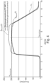
- figure 2 provides two cycles using polypropylene with different MFI (melt flow index) values with the same process settings, with a low-viscosity material (MFI 11) leading to a lower melt pressure or to a higher and more rapidly increasing cavity pressure. This indicates a different filling behavior of the cavity, from which z.
- MFI 6 melting flow index
- the cavity is underfilled if this material is processed with the process parameters of a lower-viscosity material (e.g. MFI 11).
- the decisive factor for the different filling of the cavity is the different pressurization of the melted plastic mass at the switchover point. Despite the constant switching position and the same injection speed, the mass is compressed more at high pressure, resulting in a higher density. Accordingly, less melt volume is injected into the cavity. There are various approaches to compensate for uneven filling of the cavity due to fluctuations in the flow behavior of the material.
- control variables are based on machine signals (e.g. melt pressure) and are usually referenced to one or more good part cycles.
- An alternative solution for monitoring cavity filling is the use of sensors built into the mold (cavity pressure, mold wall temperature).
- the injection molding machine is supplied with a process parameter that adapts the injection molding process in such a way that constant cavity filling is achieved.
- the progression of the cavity pressure over time in the holding pressure phase is measured. If this deviates from a comparison value, an adjusted holding pressure follows for a subsequent injection molding process.
- An injection molding process is specified in which during the holding pressure phase (P N ) of an injection molding cycle (Z (i) ) the time profile of a cavity pressure (p w ) is measured, in which at least one cavity pressure (p w ) profile is not recorded -time-dependent parameter ( pa ; p max , t max , m, ⁇ 1 , ⁇ 2 ) is determined in which the or each parameter ( pa ; p max , t max , m, ⁇ 1 , ⁇ 2 ) with a stored parameter target value (p a,0 ) is compared and in which an adjusted holding pressure value (p N ) for a subsequent injection molding cycle (Z (i+1) ) is automatically determined on the basis of the comparison result.
- An associated injection molding system includes in particular an injection mold with a Internal pressure sensor for detecting an internal mold pressure (p w ) is provided, as well as a post-pressure regulator designed to carry out the method.
- a reference variable is derived and an assessment is made as to whether readjustment is necessary. If a deviation occurs in several consecutive cycles, the most deviating parameter is readjusted.
- the switching point is automatically determined from the internal pressure curve.
- the mold cavity pressure curve is compared with a reference curve up to at least the sealing point and the injection speeds are changed using quotients from the integrals of the current and reference curves.
- the object of the invention is to specify a method for operating an injection molding machine which is further optimized with regard to mold filling and reduces or even avoids the disadvantages of the prior art.
- the object of the invention is to specify an injection molding machine for carrying out the method.
- a method for operating an injection molding machine is to be specified in which the influence of material fluctuations and/or environmental conditions that influence the material used can be compensated for as automatically as possible with regard to the molded part volume/cavity filling and the proportion of rejects can be reduced.
- the method is intended to reduce changes in the viscosity of the injection molding compound and/or disturbance variables on the tool side, such as e.g. B. compensate for a partial failure or a deterioration in cooling performance.
- any viscosity change in the material that may occur for example due to temperature fluctuations, Humidity fluctuations or fluctuations in other environmental conditions can be detected.
- an algorithm is used in the same injection molding cycle to determine a target cavity pressure profile p wkz,soll ( t ) for a holding pressure phase of this current injection molding cycle.
- a holding pressure level p mass,Hld,ref ( t ) or a holding pressure profile p mass,Hld,ref from a reference injection molding cycle is adjusted as a function of the melt pressure change k 1 detected in the injection phase.
- the melt pressure change k 1 is preferably z. B.
- melt pressure curve p mass,ref ( t ) of a good part reference injection molding cycle and the melt pressure curve p mass,act ( t ) of the current injection molding cycle now results in a new target cavity pressure curve adapted to the changed conditions, in a departure from the established opinion of experts p wkz,soll ( t ) is calculated, which takes into account the changed material and/or environmental conditions.
- a target profile of the cavity pressure is deliberately determined from cycle to cycle or at least at intervals, since it was recognized within the scope of the invention that keeping the cavity pressure constant, as is often the goal of injection molding process management in the prior art, should be deliberately abandoned .
- a new target mold cavity pressure curve p wkz,setpoint ( t ) is calculated for each shot if necessary, which is then calculated by appropriate adaptation of the holding pressure, which is a melt pressure p mass,Hld in the space in front of the plasticizing screw is approximated as closely as possible.
- a target switchover tool cavity pressure p wkz,switchover,soll can also be recalculated from shot to shot if required for the current injection molding cycle.
- a switch is then made, so that the effect according to the invention is achieved that the switching to the holding pressure phase, taking into account the viscosity, is still influenced in the current injection molding cycle.
- the holding pressure phase begins, in which the desired cavity pressure profile p wkz,soll ( t ) determined in step b) is then applied. This means that the holding pressure phase is changed by adapting the holding pressure p mass,Hld,act in such a way that the target cavity pressure curve is reached.
- a deviation from the target mold cavity pressure curve p wkz,setpoint ( t ) is compensated for iteratively by fine adjustment of the holding pressure phase in the subsequent injection molding cycles. This is expediently done by monitoring (measuring) the current cavity pressure profile p wkz,act ( t ) in the current injection molding cycle.
- the method according to the invention is thus able to detect a property change, e.g. B. to detect a change in viscosity of the injection molding compound and already in that cycle in which the knowledge is gained to make adjustments in the holding pressure phase.
- a property change e.g. B. to detect a change in viscosity of the injection molding compound and already in that cycle in which the knowledge is gained to make adjustments in the holding pressure phase.
- a preferred embodiment is characterized in that the determination of the target mold cavity pressure curve p wkz,set (t) is also dependent a pressure transmission characteristic k 2 between a cavity pressure p wkz and a corresponding mass pressure p mass and/or using a material-specific factor k mat is determined.
- the pressure transmission characteristic k 2 of a mold is understood to be a ratio between a melt pressure p mass and a resulting cavity pressure p wkz of an injection molding cycle, with individual values of the pressures mentioned also being able to be used as curves or mean values.
- the resulting pressure transmission characteristic k 2 forms a tool-specific influencing factor, which is preferably used in the following to determine the desired internal tool pressure/desired internal pressure curve.
- the inclusion of the pressure transmission characteristic k 2 of a tool ensures increased accuracy and improved mold filling and/or component quality, since in addition to the change in viscosity of the plastic melt that may occur, which is to be taken into account according to the invention, tool-specific characteristics such as e.g. B. component geometries, ie cavity geometries or geometries and designs of runners, for example as hot runners or the like, are taken into account.
- a quantity similar to injection work is measured and calculated by determining a pressure integral in the time limits t 0 and t 1 in the good part reference injection molding cycle and in the current injection molding cycle.
- a pressure integral correlates well with a processing viscosity of the melt, so that in the further course, based on such pressure integrals, a changed process control can be determined well and precisely.
- mean pressure values for example a mean cavity pressure p wkz,avg and/or a mean mass pressure p mass,avg in the injection phase or the holding pressure phase.
- the determination of the cavity pressure area p a,wkz and the mass pressure area p a,masse in the holding pressure phase can be determined in a particularly precise manner as an integral in the time limits t 2 and t 3 , which allows a highly accurate determination of the target cavity pressure p wkz, shall ( t ) allow for a subsequent cycle or the reprint resulting therefrom.
- t 2 is a point in time after the changeover point, ie a point in time of the holding pressure phase.
- t 3 is expediently after t 2 and can be selected in a particularly preferred manner as the point in time of the maximum tool pressure t wkz,max . This has the particular advantage that calculations can then already be made and, if necessary, further changes can be made at the end of the holding pressure phase in the time period after the maximum mold pressure has been reached in the same injection molding cycle.
- the change in melt pressure k 1 which is a change in the melt properties, in particular the melt viscosity, of the current injection molding cycle compared to a good part reference injection molding cycle reflects, are calculated in a preferred manner in the above procedures.
- the calculation of the melt pressure change k 1 as a ratio of the melt pressure integrals W z is the most accurate way of looking at it.
- the determinations of the change in melt pressure k 1 also work via specified ratios of the mean values or even individual melt pressure points, but with somewhat reduced accuracy/reproducibility.
- the pressure transmission characteristic k 2 which is essentially a tool-specific influencing variable, can also be formed in the above-mentioned manner using a ratio of pressure integrals, a ratio of mean values or a ratio of individual pressure values, with these determinations being of decreasing accuracy in the order mentioned . This simplifies the calculation and in particular also the observation period of the corresponding pressures required for the calculation.
- pressures, mean values or pressure integrals are set in relation, with the corresponding values of the mold pressure in the holding pressure phase being in the numerator and the corresponding values of the melt pressure in the holding pressure phase being in the denominator.
- a further preferred embodiment is characterized in that at least one cavity pressure sensor is used to record the cavity pressure curve p wkz,ref ( t ) over time in the good part reference injection molding cycle and/or the current injection molding cycle p wkz,act ( t ) within the injection and/or holding pressure phase.
- a target cavity pressure curve p wkz,soll ( t ) can be calculated in a simple manner according to the formula given above, with the associated cavity pressure curve p wkz,ref ( t ) of the good part reference injection molding cycle being used as the starting point of the factors k mat and k 1 and k 2 is modified.
- a further preferred embodiment is characterized in that in the case of an injection mold which has a plurality of cavity pressure sensors, the method is carried out in parallel for one or more of these cavity pressure sensors.
- a further preferred embodiment is characterized in that during the holding pressure phase of the current injection molding cycle, the actual cavity pressure p wkz,act resulting from the calculated variation in holding pressure is measured and compared with the target cavity pressure p wkz,soll .
- a further preferred embodiment is characterized in that the method is used for holding pressure phases with several profile stages.
- the method is also particularly suitable for using holding pressure phases with several profile stages.
- the method according to the invention can advantageously be used both for each profile step individually and for an average over the profile steps.
- a further preferred embodiment is characterized in that to determine a current switchover point in the current injection molding cycle, the switchover tool internal pressure p wkz,switch,ref of the good part reference injection molding cycle is determined/read at the switchover point of the good part reference injection molding cycle, then a switchover tool internal pressure p wkz,switch,ref of the good-part reference injection molding cycle corresponding set switching cavity pressure p wkz,umschalt,soll on the set cavity pressure curve p wkz,soll ( t ) of the current Injection molding cycle is determined and as soon as p wkz,act ⁇ p wkz,umschalt,soll applies in the current injection molding cycle, a switch is made from the injection phase to the holding pressure phase.
- the associated switchover pressure in the current injection molding cycle is additionally calculated and switchover is carried out at this determined switchover pressure. This enables switching based only on a melt pressure measurement.
- the formulas given refer to the melt pressure curves necessary/sufficient to achieve the desired cavity pressure curve in the holding pressure phase.
- the corresponding pressure integrals (formula a)), average values (formula b)) or individual values (formula c)) are suitable for this, whereby the accuracy decreases somewhat from a) to c), but the computational effort also decreases.
- Another preferred embodiment is characterized in that during the holding pressure phase of the current injection molding cycle, the actual cavity pressure curve p wkz,act ( t ) of the current injection molding cycle is compared with the target cavity pressure curve p wkz,soll ( t ) and the holding pressure curve p mass,Hld ,act ( t ) is iteratively adjusted during the current injection molding cycle or in a subsequent injection molding cycle so that a deviation over several cycles is compensated for.
- the filling process of one or more cavities is measured by means of at least one or preferably more cavity pressure sensors.
- an algorithm preferably stores at least one of the following parameters: a progression of the cavity pressure signal over time, the time at which the cavity pressure increases due to the plastic melt flowing past, a maximum pressure value, and a pressure area under the curve. This deduces at what percentage of the filling volume or where on the flow path the sensor or sensors are placed.
- the parameters that result from the algorithm are stored as a reference in distance-dependent pressure points during one or more learning cycles in the injection molding machine.
- the viscosity of the plastic melt changes, for example due to a batch change, this is measured during the injection phase.
- the change in pressure in the injection phase which is derived from the change in viscosity, is determined in the inventive method, from which it calculates a new viscosity-dependent desired internal mold pressure profile for the holding pressure phase.
- a new switching cavity pressure for the currently active cycle is calculated via the target cavity pressure curve and thus switched over depending on the viscosity.
- a new target cavity pressure curve for one or more cavity pressure sensors for the holding pressure phase is calculated on the basis of a change in the pressure requirement (viscosity) in the injection phase.
- the holding pressure level and preferably the switchover time in the current cycle are thus adjusted via the described ratio.
- material-specific factors are used to calculate the holding pressure level, which take into account the shrinkage and cooling behavior of the different plastics.
- the cavity pressure resulting from the change in the holding pressure is compared with the previously calculated setpoint cavity pressure. If deviations are found, the holding pressure level z. B. over the control cycle an amplification factor k 3 between viscosity and pressure change in the injection phase for the next cycle adjusted.
- This method is also preferably used for injection and holding pressure phases with several profile stages.
- the viscosity-dependent recalculation of the target mold cavity pressure profile of the method according to the invention is also used to shift the switchover point by specifying the newly calculated pressure at the switchover position of the screw from the reference cycle as the switchover condition. This results in a temporal, compression-related shift in the cavity pressure.
- RSP fluctuations via an increase in melt pressure can also be taken into account.
- the pressure drop can be determined over the flow path length.
- the sensor that is preferably placed at the end of the flow path is used for control.
- FIG 1 a screw 1 in a screw cylinder 2 of a plastic injection molding machine (not shown) is shown in a highly schematic manner.
- a screw 1 located in a screw antechamber 3 and shown schematically in a cavity 4 is a polypropylene material (PP material) with a melt flow index (melt flow index MFI) of 6.
- PP material polypropylene material
- melt flow index MFI melt flow index
- MFI melt flow index
- the higher-viscosity material polypropylene MFI 6
- an increased pressure requirement is necessary in order to bring the higher-viscosity melt into cavity 4.
- the melt of the PP MFI 6 material is more strongly compressed at a higher pressure level, as a result of which a smaller filling volume arrives in the cavity 4 than with a lower-viscosity PP MFI 11 material.
- the melt pressure curve or melt pressure is understood to mean pressures or pressure curves that form in an antechamber 3 of the screw during a process. Such melt pressures or such melt pressure curves are chronologically assigned below to an injection phase of an injection molding process.
- the terms “cavity pressure” and “cavity pressure curve” refer to pressures or pressure curves measured in a cavity or generally in the interior of a mold. In terms of time, the terms “cavity pressure” and “cavity pressure curve” in the context of this description mainly refer to the holding pressure phase of an injection molding process .
- the term “holding pressure/holding pressure profile” is understood to mean the melt pressure during a holding pressure phase, ie the pressure of the melt that is in the space in front of the screw 3 .
- a melt pressure profile of the lower-viscosity melt material PP MFI 11 runs below the melt pressure or melt pressure profile of a higher-viscosity melt material made of PP MFI 6 material during the entire injection phase of the injection molding process shown.
- a mold cavity pressure curve of the thinner (lower viscous) material PP MFI 11 is arranged throughout the holding pressure phase above the mold cavity pressure or the mold cavity pressure curve of a melt made of a higher-viscosity material MFI 6 .
- the determined pressure curves i.e. the melt pressure (melt pressure curve) and the cavity pressure (cavity pressure curve) of the low-viscosity polypropylene (PP MFI 11) for further explanation is used as a reference curve R, from which, for example, adjustments according to the invention are carried out.
- the viscosity for example, increases analogously to the course of the PP MFI 6 due to a batch change to a polypropylene with a higher viscosity.
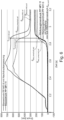
- figure 3 shows for a PP MFI 6 (higher viscosity polypropylene) in broken line the course of the mass pressure p mass during the injection and the holding pressure phase.
- the diagram according to figure 3 the melt pressure profile p mass of a PP MFI 11 (low-viscosity polypropylene melt) in a dark dotted line during the injection and holding pressure phases.
- a narrower hatched area between time limits t 0 and t 1 represents a melt pressure area pa ,masse below the melt pressure curve of the PP MFI 6.
- This melt pressure area corresponds to the injection work W z,ref in the limits between t 0 and t 1 , with the lower time limit t 0 is after closing a non-return valve and the upper time limit t 1 is still before a switching point.
- melt pressure area pa mass of the PP MFI 11, i.e. the thinner polypropylene melt.
- This area corresponds to the injection work W z , act and is smaller within the limits t 0 to t 1 than the injection work W z,ref of the thicker (higher viscosity) PP-MFI-6 melt.
- melt pressure curve of the two PP melts MFI 6 and MFI 11 shows the same pressure course during the holding pressure phase (prior art). This results in cavity pressures that vary in the lower part of the diagram.
- the bright dotted line represents the cavity pressure profile p wkz ( t ) of the lower-viscosity PP melt (MFI 11). This curve is compared to a mold cavity pressure curve of a PP-MFI-6 melt, which is more viscous and shown with a dark dashed line, at a higher level.
- melt pressure curve of the PP-MFI-11 melt can be viewed as the reference melt pressure curve p mass,ref and the melt pressure curve p mass,act of the PP-MFI-6 melt can be regarded as the melt pressure curve p mass,act of the current injection molding cycle.
- the change in melt pressure k 1 preferably additionally taking into account a pressure transmission characteristic k 2 and a material-dependent factor k mat from the cavity pressure of the good part reference injection molding cycle (here: cavity pressure of the PP-MFI-11 melt) on a target cavity pressure curve p wkz,soll ( t ) converted for the more viscous PP-MFI-6 melt to be processed in the current injection molding cycle.
- a pressure transmission characteristic k 2 and a material-dependent factor k mat from the cavity pressure of the good part reference injection molding cycle (here: cavity pressure of the PP-MFI-11 melt) on a target cavity pressure curve p wkz,soll ( t ) converted for the more viscous PP-MFI-6 melt to be processed in the current injection molding cycle.
- the factor k 2 is determined from a ratio of the pressure integrals over the mold cavity pressure curve during at least part of the holding pressure phase p wkz,md ( t ) and over the melt pressure p masse,Hld ( t ) each within the limits t 2 determined until t 3 .
- t 2 is a point in time at or after the switching point.
- t 3 is a point in time after t 2 and before the end of the holding pressure phase.
- a point in time t wkz,max of the maximum internal mold pressure p wkz,masse is preferably used here for t 3 .
- the factor k 2 can also be formed as the quotient of the average values of the cavity pressure p wkz,Hld,avg and the melt pressure p mass,Hld,avg during the holding pressure phase.
- a material-specific factor k mat is determined empirically and introduces material-specific changes in properties of a melt of the current injection molding cycle compared to the melt of the good part reference injection molding cycle.
- a holding pressure curve p mass,Hld,act ( t ) corresponding to the target cavity pressure curve p wkz,soll ( t ) can now be calculated via the pressure transmission characteristic k 2 .
- the corresponding target holding pressure can be determined with little computational effort by dividing the target cavity pressure profile by the factor k 2 . This applies both to the use of pressure integrals over a sub-range of the mold cavity pressure and the melt pressure as well as to their mean values or even individual values.
- This value for the cavity pressure in the good-part reference injection molding cycle at the switchover point is converted in a manner according to the invention to a target cavity pressure p wkz,switch,soll and when this cavity pressure p wkz,switch,soll in the current injection molding cycle is reached, a switch is made in the current injection molding cycle. This then results in the switchover time t switchover,act .
- the holding pressure profile p mass,Hld,act ( t ) is traversed in such a way that the resulting actual cavity pressure profile p wkz,act ( t ) of the current injection molding cycle is as close as possible, ideally exactly, to the target cavity pressure profile p wkz,soll ( t ) follows.
- target cavity pressure p wkz,soll ( t ) does not quite succeed in reaching such an exact level, this is approximated iteratively in subsequent cycles, if necessary.
- the method according to the invention is designed for use on electromechanical and hydromechanical injection molding machines of all sizes. It can therefore be used in all new machines and as a retrofit. At least one cavity pressure sensor integrated into the machine is required.
- Injection molding machines that are operated with the method are able to automatically compensate for negative effects of, for example, batch fluctuations on the quality of the molded part. Likewise, negative effects on the molded part quality when the machines are restarted (after malfunctions or standstill) are automatically compensated for by calculating the optimal target mold cavity pressure curve or key figures derived from it. The machine operator does not have to intervene as often in the production process, for example to manually adjust setting parameters. The differences in quality of the individual molded parts are reduced to a minimum, even with changing production conditions. Cost savings through automation and process reliability are the direct result.
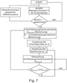
- melt pressure curve p mass,ref ( t ) that comes from a good part reference injection molding cycle. Furthermore, a current melt pressure profile p mass,act ( t ) is recorded, for example measured, during the injection phase of an actual injection molding cycle.
- the reference mass pressure curve p mass,ref ( t ) and the current mass pressure curve p mass,act ( t ) are compared. If the actual melt pressure curve p mass,act ( t ) is not equal to the reference melt pressure curve p mass,ref ( t ) or the difference falls below a certain threshold value, the further course of the injection molding cycle is not modified. If the difference between the reference melt pressure curve is exceeded p masse,ref ( t ) and the actual melt pressure curve p masse,act ( t ) have a specific limit value, then a target cavity pressure curve p wkz , soll ( t ) is first calculated as a function of the quotient.
- This setpoint internal mold pressure profile p wkz,soll ( t ) should be achieved as precisely as possible in the holding pressure phase of the current injection molding cycle.
- a switchover tool internal pressure p wkz , switchover is preferably calculated, which also depends on the level of the quotient of the reference mass pressure curve p mass,ref ( t ) and the actual mass pressure curve p mass , act ( t ) in the injection phase. After these calculations, the holding pressure p mass , Hld is adjusted in such a way that the target cavity pressure curve p wkz,setpoint ( t ) is followed as precisely as possible.
- the changeover point is also adjusted so that a changeover takes place at the calculated changeover tool internal pressure p wkz,umschalt .
- the actual cavity pressure curve p wkz,act ( t ) during the holding pressure phase is monitored (measured). If the actual cavity pressure profile p wkz,act ( t ) differs from the target cavity pressure profile p wkz,soll ( t ) or falls below a certain limit value, there is no further adjustment of the holding pressure p mass , Hld in the next cycle, i.e. the next cycle is run with the same cavity pressure curve as the current cycle. If the difference exceeds a certain limit, the reprint will be in the next cycle adjusted iteratively, so that the target cavity pressure curve p wkz,soll ( t ) is reached after a few cycles at the latest.
Landscapes
- Engineering & Computer Science (AREA)
- Manufacturing & Machinery (AREA)
- Mechanical Engineering (AREA)
- Injection Moulding Of Plastics Or The Like (AREA)
Claims (18)
- Procédé servant à faire fonctionner une machine de moulage par injection, comprenant les étapes suivantes :a) après un cycle de moulage par injection de référence de pièce acceptée appris dans une phase d'apprentissage, dans un cycle de moulage par injection actuel : détection d'une modification de pression massique k 1 par rapport à une pression massique de référence de pièce acceptée pmasse,ref pendant au moins une partie d'une phase d'injection du cycle de moulage par injection actuel par la mesure d'une pression massique actuelle pmasse,act et comparaison de la pression massique actuelle pmasse,act à la pression massique de référence de pièce acceptée pmasse,ref,b) détermination d'un tracé de pression interne d'outil nominale pwkz,soll(t) pour une phase de maintien en pression du cycle de moulage par injection actuel, dans lequel pour cela, un tracé de pression interne d'outil pwkz,ref(t) du cycle de moulage par injection de référence de pièce acceptée est adapté au moins en fonction de la modification de pression massique k1 détectée à l'étape a), etc) le tracé de maintien en pression pmasse,Hld,act(t) du cycle de moulage par injection actuel commence ainsi qu'un tracé de pression interne d'outil réelle pwkz,act(t) du cycle de moulage par injection actuel passe au moins plus près le long du tracé de pression interne d'outil nominale pwxz,soll(t) qu'un tracé de pression interne d'outil pwkz,ref(t) inchangé par rapport au cycle de référence de pièce acceptée.
- Procédé selon la revendication 1,
caractérisé en ce que
le procédé, avant, après ou pendant l'étape b), présente en outre les étapes suivantes :b1) détermination d'une pression interne d'outil de commutation nominale pwkz,umschalt,soll pour le cycle de moulage par injection actuel au moins en fonction de la modification de pression massique k 1 détectée à l'étape a),b2) commutation une fois la pression interne d'outil de commutation nominale Pwkz,umschalt,soll déterminée à l'étape b1) atteinte. - Procédé selon l'une des revendications précédentes,
caractérisé en ce que
la détermination du tracé de pression interne d'outil nominale pwxz,soll(t) est déterminée en plus en fonction d'une caractéristique de transfert de pression entre une pression interne d'outil pwkz et une pression massique correspondante pmasse et/ou en utilisant un facteur kmat spécifique au matériau. - Procédé selon l'une des revendications précédentes,
caractérisé en ce que
dans le cycle de moulage par injection de référence de pièce acceptée et dans le cycle de moulage par injection actuel, une intégrale de pression massique pendant l'injection est déterminée en tant que grandeur de mesure qui corrèle avec une viscosité de traitement de la masse fondue, en particulier selon la formule tinj,start ou un temps après la fermeture d'un verrouillage de courant inverse ett1 un temps de la commutation tinj,umschalt ou un temps qui est après t0 mais avant tinj,umschalt.
 - Procédé selon l'une des revendications précédentes,
caractérisé en ce que
dans le cycle de moulage par injection de référence de pièce acceptée et/ou dans le cycle de moulage par injection actuel, au moins une des grandeurs suivantes est déterminée en plus et enregistrée ci-besoin :- pression interne d'outil maximale pwkz,max ainsi que- le temps twkz,max correspondant,- une baisse de la pression interne d'outil après atteinte du maximum (m 1),- une moyenne de pression interne d'out pwkz,avg et/ou une moyenne de pression massique pmasse,avg pendant la phase d'injection et/ou une moyenne de pression interne d'outil pwkz,Hld,avg et/ou une moyenne de pression massique pmasse,Hld,avg pendant la phase de maintien en pression,- une aire de pression interne d'outil pa,wkz pendant la phase de maintien en pression, en particulier comme intégrale de pression selon la formule suivante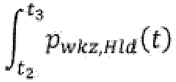 - une aire de pression massique pa,masse pendant la phase de maintien en pression, en particulier en tant qu'intégrale de pression selon la formule suivante
 pwkz,Hld(t) est le tracé de pression interne d'outil dans la phase de maintien en pression,pmasse,Hld(t) est le tracé de pression massique dans la phase de maintien en pression,pwkz,avg est une valeur médiane de la pression interne d'outil pendant la phase d'injection,pmasse,avg est une valeur médiane de la pression massique pendant la phase d'injection,pwkz,Hld,avg est une valeur médiane de la pression interne d'outil pendant la phase de maintien en pression,pmasse,Hld,avg est une valeur médiane de la pression massique dans la phase de maintien en pression,t2 est un temps au ou après le point de commutation, en particulier le temps de commutation ett3 est un temps après t2 , par exemple le temps de la fin de la phase de maintien en pression tHld,End ou un temps avant la fin de la phase de maintien en pression, en particulier le temps twkz,max de la pression interne d'outil maximale du cycle respectif.
 - Procédé selon l'une des revendications précédentes,
caractérisé en ce que
un rapport de l'intégrale de pression pendant l'injection dans le cycle de moulage par injection actuel et de l'intégrale de pression pendant l'injection du cycle de moulage par injection de référence de pièce acceptée est déterminé en tant que modification de pression massique k 1, en particulier selon la formule
un rapport de la valeur médiane de la pression massique pendant l'injection dans le cycle de moulage par injection actuel et de la valeur médiane de la pression massique pendant l'injection du cycle de moulage par injection de référence de pièce acceptée est déterminé en tant que modification de la pression massique k 1, en particulier selon la formule
un rapport d'une ou plusieurs valeur(s) individuelle(s) de pression pendant l'injection dans le cycle de moulage par injection actuel et pendant l'injection du cycle de moulage par injection de référence de pièce acceptée est déterminé en tant que modification de la pression massique k 1, en particulier selon la formule
- Procédé selon l'une des revendications précédentes,
caractérisé en ce que
une dépendance (k 2) entre la pression interne d'outil pwkz et la pression massique pmasse pendant la phase de maintien en pression dans le cycle de moulage par injection de référence de pièce acceptée et dans le cycle de moulage par injection actuel est déterminée en tant que caractéristique de transfert de pression, en particulier selon au moins une des formulesa)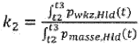 b)
b) c)où : - pmasse,Hld(t) est le tracé de pression massique pendant la phase de maintien en pression,
 - pwkz,Hld(t) est le tracé de pression interne d'outil pendant la phase de maintien en pression,- t2 est un temps au ou après le temps de commutation, en particulier le temps de commutation tinj,umschalt et- t3 est le temps de la fin de la phase de maintien en pression tHld,End ou un temps avant la fin de la phase de maintien en pression mais après t2 .
 - Procédé selon l'une des revendications précédentes,
caractérisé en ce que
le tracé de pression interne d'outil temporel pwkz,ref(t) du cycle de moulage par injection de référence de pièce acceptée et/ou du cycle d'injection actuel pwkz,act(t) à l'intérieur de la phase d'injection et/ou de maintien en pression est enregistré au moyen d'au moins un capteur de pression interne d'outil. - Procédé selon l'une des revendications précédentes,
caractérisé en ce que
le tracé de pression interne d'outil nominale pwkz,soll(t) du cycle d'injection actuel est déterminé selon la formule kmat est un ou plusieurs facteur (s) spécifique (s) au matériau déterminé(s) de manière empirique etk1 , k2 sont des facteurs qui tiennent compte au moins du comportement d'écoulement de la masse fondue et/ou d'une dépendance spécifique à l'outil entre la pression massique pmasse et la pression interne d'outil pwkz résultante.
 - Procédé selon l'une des revendications précédentes,
caractérisé en ce que
la dépendance k2 est calculée à partir d'une fonction de transfert de pression f(pmasse,Hld,ref,i) enregistrée dans le cycle de moulage par injection de référence de pièce acceptée, où
- Procédé selon l'une des revendications précédentes,
caractérisé en ce que
dans un outil de moulage par injection qui présente plusieurs capteurs de pression interne d'outil, le procédé est exécuté en parallèle pour un ou plusieurs de ces capteurs de pression interne d'outil. - Procédé selon l'une des revendications précédentes,
caractérisé en ce que
pendant la phase de maintien en pression du cycle d'injection actuel, la pression interne d'outil réelle pwkz,act fournie par la modification de maintien en pression calculée est mesurée et comparée à la pression interne d'outil nominale pwkz,soll . - Procédé selon l'une des revendications précédentes,
caractérisé en ce que
le procédé est appliqué pour des phases de maintien en pression à plusieurs degrés de profilage. - Procédé selon l'une des revendications précédentes,
caractérisé en ce que
pour déterminer un point de commutation actuel dans le cycle d'injection actuel, la pression interne d'outil de commutation pwkz,umschalt,réf du cycle de moulage par injection de référence de pièce acceptée est déterminée/lue au point de commutation du cycle de moulage par injection de référence de pièce acceptée, ensuite, une pression interne d'outil de commutation nominale pwkz,umschalt,soll correspondant à la pression interne d'outil de commutation pwkz,umschalt,ref du cycle de moulage par injection de référence de pièce acceptée est déterminée sur la courbe de pression interne d'outil nominale pwkz,soll(t) du cycle de moulage par injection actuel et dès que l'on a pwkz,act ≥ pwkz,umschalt,soll dans le cycle de moulage par injection actuel, on commute de la phase d'injection à la phase de maintien en pression. - Procédé selon l'une des revendications précédentes,
caractérisé en ce que
pour atteindre le tracé de pression interne d'outil nominale pwkz,soll(t) dans le cycle d'injection actuel, le tracé de maintien en pression nominale pmasse,Hld,soll(t) nécessaire à cela dans le cycle de moulage par injection actuel est calculé selon l'une des formules suivantes


- Procédé selon l'une des revendications précédentes,
caractérisé en ce que
pendant la phase de maintien en pression du cycle de moulage par injection actuel, la courbe de pression interne d'outil réelle pwkz,act(t) du cycle de moulage par injection actuel est comparée à la courbe de pression interne d'outil nominale pwkz,soll(t), et le tracé de maintien en pression pmasse,Hld,act(t) pendant le cycle de moulage par injection actuel ou dans un cycle de moulage par injection suivant est adapté de manière itérative de façon à ce qu'un écart soit compensé sur plusieurs cycles. - Procédé selon l'une des revendications précédentes,
caractérisé en ce que
le tracé de maintien en pression nominal pmasse,Hld,soll(t) du cycle de moulage par injection actuel est calculé selon la formule
- Machine de moulage par injection qui est conçue et formée pour exécuter le procédé selon l'une ou plusieurs des revendications 1 à 17.
Applications Claiming Priority (2)
| Application Number | Priority Date | Filing Date | Title |
|---|---|---|---|
| DE102018126313.9A DE102018126313A1 (de) | 2018-10-23 | 2018-10-23 | Verfahren zum Betreiben einer Spritzgießmaschine, insbesondere hinsichtlich verbesserter konstanter Werkzeugfüllung, sowie Spritzgießmaschine zur Durchführung des Verfahrens |
| PCT/EP2019/076368 WO2020083611A1 (fr) | 2018-10-23 | 2019-09-30 | Procédé servant à faire fonctionner une machine de moulage par injection, en particulier en termes d'amélioration du remplissage de moule constant, ainsi que machine de moulage par injection servant à mettre en œuvre le procédé |
Publications (2)
| Publication Number | Publication Date |
|---|---|
| EP3870422A1 EP3870422A1 (fr) | 2021-09-01 |
| EP3870422B1 true EP3870422B1 (fr) | 2023-03-15 |
Family
ID=68109316
Family Applications (1)
| Application Number | Title | Priority Date | Filing Date |
|---|---|---|---|
| EP19780221.8A Active EP3870422B1 (fr) | 2018-10-23 | 2019-09-30 | Procédé servant à faire fonctionner une machine de moulage par injection, en particulier en termes d'amélioration du remplissage de moule constant, ainsi que machine de moulage par injection servant à mettre en oeuvre le procédé |
Country Status (9)
| Country | Link |
|---|---|
| US (1) | US11883986B2 (fr) |
| EP (1) | EP3870422B1 (fr) |
| KR (1) | KR102799232B1 (fr) |
| CN (1) | CN112888544B (fr) |
| DE (1) | DE102018126313A1 (fr) |
| ES (1) | ES2947447T3 (fr) |
| MX (1) | MX2021004264A (fr) |
| PL (1) | PL3870422T3 (fr) |
| WO (1) | WO2020083611A1 (fr) |
Cited By (1)
| Publication number | Priority date | Publication date | Assignee | Title |
|---|---|---|---|---|
| DE102023124804A1 (de) | 2023-09-14 | 2025-03-20 | Kraussmaffei Technologies Gmbh | Verfahren zur Generierung und/oder Adaption eines geometrischen Meta-Modells für ein in einem Urformprozess herzustellendes Formteil, insbesondere für ein in einem Spritzgießprozess herzustellendes Spritzgießformteil |
Families Citing this family (7)
| Publication number | Priority date | Publication date | Assignee | Title |
|---|---|---|---|---|
| US11358317B2 (en) | 2018-05-02 | 2022-06-14 | iMFLUX Inc. | Systems and methods for controlling injection molding using predicted cavity pressure |
| CN113059774B (zh) * | 2021-03-15 | 2022-08-30 | 伯乐智能装备股份有限公司 | 一种控制注塑成型保压过程的方法 |
| CN114734602A (zh) * | 2022-03-28 | 2022-07-12 | 浙江凯华模具有限公司 | 一种注塑过程模具温度压力的双向补偿控制方法 |
| WO2023184207A1 (fr) * | 2022-03-30 | 2023-10-05 | 浙江凯华模具有限公司 | Procédé de réglage par compensation bidirectionnelle pour la température et la pression d'un moule pendant un processus de moulage par injection |
| CN117245852A (zh) * | 2023-03-31 | 2023-12-19 | 浙江西诺模具有限公司 | 一种注塑机 |
| DE102024135837B3 (de) * | 2024-12-03 | 2025-08-21 | Kraussmaffei Technologies Gmbh | Spritzgussverfahren unter Verwendung einer Plastifiziereinheit mit einer Ultraschalleinheit |
| CN119356418B (zh) * | 2024-12-24 | 2025-03-21 | 深圳市俱进纸品包装有限公司 | 一种全自动皮壳机的压力控制系统及方法 |
Family Cites Families (17)
| Publication number | Priority date | Publication date | Assignee | Title |
|---|---|---|---|---|
| AT333024B (de) | 1972-12-05 | 1976-10-25 | Fur Verbrennungsmotoren Prof D | Digitale regelanordnung fur einen druckmittelbetatigten arbeitszylinder einer schneckenspritzgiessmaschine |
| DE3524310C1 (de) | 1985-04-11 | 1986-06-19 | Wilbrand Prof. Dr.-Ing. 8700 Würzburg Woebcken | Verfahren und Vorrichtungen zum geregelten Spritzgiessen auf verschiedenen Kunststoff-Spritzgiessmaschinen mit stets gleichen Formteileigenschaften und gleichen Massen |
| AT404076B (de) * | 1994-08-31 | 1998-08-25 | Battenfeld Kunststoffmasch | Verfahren zum automatischen bestimmen des optimalen arbeitspunktes einer spritzgiessmaschine |
| DE59813455D1 (de) | 1997-08-21 | 2006-05-11 | Kistler Holding Ag Winterthur | Verfahren zum Regeln einer Spritzgiessanlage für Kunststoff-Materialien |
| DE19913527C2 (de) * | 1999-03-25 | 2001-09-27 | Battenfeld Gmbh | Verfahren und Vorrichtung zur Kompensation der Meßwertdrift eines Schmelzedrucksensors |
| JP2001277319A (ja) * | 2000-04-03 | 2001-10-09 | Fanuc Ltd | 成形特性判別方法及び射出成形機 |
| DE102005016618B3 (de) | 2005-04-12 | 2006-09-28 | Battenfeld Gmbh | Verfahren zur Bestimmung der Schmelzehomogenität |
| DE102005032367A1 (de) | 2005-07-08 | 2007-01-11 | Priamus System Technologies Ag | Verfahren zum Überwachen und/oder Regeln der Schmelzebefüllung von zumindest einer Kavität |
| DE102007061775A1 (de) | 2007-12-20 | 2009-07-02 | Geiger Technik Gmbh | Spritzgussverfahren und zugehörige Anlage |
| EP2174769A1 (fr) * | 2008-10-07 | 2010-04-14 | Neo-plastic Dr. Doetsch Diespeck GmbH | Procédé de moulage par injection et installation correspondante |
| AT511391B1 (de) | 2011-10-18 | 2013-02-15 | Engel Austria Gmbh | Verfahren zur quantifizierung von prozessschwankungen bei einem einspritzvorgang einer spritzgiessmaschine |
| DE102013111257B3 (de) | 2013-10-11 | 2014-08-14 | Kraussmaffei Technologies Gmbh | Verfahren zur Prozessführung eines Formfüllvorgangs einer Spritzgießmaschine |
| JP5815646B2 (ja) * | 2013-11-15 | 2015-11-17 | ファナック株式会社 | 射出成形機の制御装置 |
| CA2994011C (fr) * | 2015-08-27 | 2020-04-14 | iMFLUX Inc. | Appareil de moulage par injection et procede permettant de le commander |
| DE102015117237B3 (de) * | 2015-10-09 | 2017-03-23 | Kraussmaffei Technologies Gmbh | Verfahren zur Bestimmung eines realen Volumens einer spritzgießfähigen Masse in einem Spritzgießprozess |
| DE102017207586A1 (de) * | 2017-05-05 | 2018-11-08 | Arburg Gmbh + Co Kg | STEUERN UND REGELN DES DRUCKS EINER ZYKLISCH ARBEITENDEN SPRITZGIEßMASCHINE |
| US11358317B2 (en) | 2018-05-02 | 2022-06-14 | iMFLUX Inc. | Systems and methods for controlling injection molding using predicted cavity pressure |
-
2018
- 2018-10-23 DE DE102018126313.9A patent/DE102018126313A1/de active Pending
-
2019
- 2019-09-30 WO PCT/EP2019/076368 patent/WO2020083611A1/fr not_active Ceased
- 2019-09-30 PL PL19780221.8T patent/PL3870422T3/pl unknown
- 2019-09-30 MX MX2021004264A patent/MX2021004264A/es unknown
- 2019-09-30 US US17/282,923 patent/US11883986B2/en active Active
- 2019-09-30 CN CN201980068130.XA patent/CN112888544B/zh active Active
- 2019-09-30 KR KR1020217014090A patent/KR102799232B1/ko active Active
- 2019-09-30 EP EP19780221.8A patent/EP3870422B1/fr active Active
- 2019-09-30 ES ES19780221T patent/ES2947447T3/es active Active
Cited By (2)
| Publication number | Priority date | Publication date | Assignee | Title |
|---|---|---|---|---|
| DE102023124804A1 (de) | 2023-09-14 | 2025-03-20 | Kraussmaffei Technologies Gmbh | Verfahren zur Generierung und/oder Adaption eines geometrischen Meta-Modells für ein in einem Urformprozess herzustellendes Formteil, insbesondere für ein in einem Spritzgießprozess herzustellendes Spritzgießformteil |
| WO2025056256A1 (fr) | 2023-09-14 | 2025-03-20 | Kraussmaffei Technologies Gmbh | Procédé de génération et/ou d'adaptation d'un méta-modèle géométrique pour une pièce moulée à réaliser dans un procédé de moulage, en particulier pour une pièce moulée par injection à réaliser dans un procédé de moulage par injection |
Also Published As
| Publication number | Publication date |
|---|---|
| WO2020083611A1 (fr) | 2020-04-30 |
| PL3870422T3 (pl) | 2023-08-14 |
| CN112888544A (zh) | 2021-06-01 |
| MX2021004264A (es) | 2021-05-28 |
| ES2947447T3 (es) | 2023-08-09 |
| US20210387392A1 (en) | 2021-12-16 |
| US11883986B2 (en) | 2024-01-30 |
| EP3870422A1 (fr) | 2021-09-01 |
| KR20210078509A (ko) | 2021-06-28 |
| CN112888544B (zh) | 2023-05-05 |
| KR102799232B1 (ko) | 2025-04-22 |
| DE102018126313A1 (de) | 2020-04-23 |
Similar Documents
| Publication | Publication Date | Title |
|---|---|---|
| EP3870422B1 (fr) | Procédé servant à faire fonctionner une machine de moulage par injection, en particulier en termes d'amélioration du remplissage de moule constant, ainsi que machine de moulage par injection servant à mettre en oeuvre le procédé | |
| EP3055116B1 (fr) | Procédé de guidage du processus d'un cycle de remplissage d'un moule d'une machine de moulage par injection | |
| DE19536566C1 (de) | Verfahren zur Regelung des Werkzeuginnendrucks an einer zyklisch arbeitenden Maschine | |
| DE2914944C2 (de) | Vorrichtung zum Steuern der Drehzahl und des Staudruckes beim Plastifizier- und Dosiervorgang einer Kunststoff - Schneckenspritzgießmaschine | |
| DE2751225C3 (de) | Vorrichtung mit einer nach dem Siebpaket eines Schneckenextruders angeordneten Schmelzindex-Meßeinrichtung und Verfahren zum Regeln der Viskosität von aufgeschmolzenem und auszuformendem Kunststoff | |
| EP3057760B1 (fr) | Procédé permettant d'évaluer les propriétés techniques d'outils de moulage par injection | |
| EP2583811B2 (fr) | Procédé de quantification de basculements de procédés dans le cadre d'un processus d'injection d'une machine de moulage par injection | |
| EP0897786B1 (fr) | Procédé de régulation d'une machine de moulage par injection de matières plastiques | |
| DE102015117237B3 (de) | Verfahren zur Bestimmung eines realen Volumens einer spritzgießfähigen Masse in einem Spritzgießprozess | |
| CH692383A5 (de) | Verfahren zur Regelung der Heisskanalheizung eines Mehrkavitäten-Spritzgiesswerkzeugs. | |
| DE69617974T2 (de) | Kombinationssteuerung für das spritzgiessen | |
| DE19544634A1 (de) | Verfahren zum Blasformen von Hohlkörpern aus thermoplastischem Kunststoff | |
| DE102014014231A1 (de) | Verfahren zur Bestimmung eines Sollwerts für einen Einstellparameter | |
| EP1390190A1 (fr) | Procede et dispositif de regulation de pression dans une extrudeuse de degazage a une seule vis ou une extrudeuse en cascade | |
| EP0451239B1 (fr) | Procede de fabrication de pieces creuses en matiere thermoplastique | |
| EP0784535B1 (fr) | Procede concu pour influer sur des valeurs de consigne de machines, et dispositif de mise en oeuvre dudit procede | |
| DE69109614T2 (de) | Verfahren zum feststellen von harzeigenschaften bei einer spritzgiessmaschine. | |
| DE3608973C2 (de) | Verfahren und Vorrichtung zum Steuern des Umschaltens von der Nachdruckphase in die isochore Abkühlphase beim Spritzgießen thermoplastischer Kunststoffe | |
| DE102007012199A1 (de) | Verfahren zum Betreiben einer Plastifizierungseinrichtung, z. B. eines Extruders oder einer Spritzgussmaschine | |
| EP2174769A1 (fr) | Procédé de moulage par injection et installation correspondante | |
| DE102004051109B4 (de) | Verfahren zum Betrieb einer Spritzgießmaschine | |
| WO2019154631A1 (fr) | Procédé destiné à faire fonctionner une extrudeuse et extrudeuse | |
| DE2532429A1 (de) | Verfahren und einrichtung zum spritzgiessen von kunststoffen | |
| DE69125698T2 (de) | Verfahren zum feststellen eines abnormalen füllens bei einer spritzgiessmaschine | |
| DD227383B5 (de) | Verfahren und Einrichtung zur Regelung des Spritzgiessprozesses |
Legal Events
| Date | Code | Title | Description |
|---|---|---|---|
| STAA | Information on the status of an ep patent application or granted ep patent |
Free format text: STATUS: UNKNOWN |
|
| STAA | Information on the status of an ep patent application or granted ep patent |
Free format text: STATUS: THE INTERNATIONAL PUBLICATION HAS BEEN MADE |
|
| PUAI | Public reference made under article 153(3) epc to a published international application that has entered the european phase |
Free format text: ORIGINAL CODE: 0009012 |
|
| STAA | Information on the status of an ep patent application or granted ep patent |
Free format text: STATUS: REQUEST FOR EXAMINATION WAS MADE |
|
| 17P | Request for examination filed |
Effective date: 20210525 |
|
| AK | Designated contracting states |
Kind code of ref document: A1 Designated state(s): AL AT BE BG CH CY CZ DE DK EE ES FI FR GB GR HR HU IE IS IT LI LT LU LV MC MK MT NL NO PL PT RO RS SE SI SK SM TR |
|
| DAV | Request for validation of the european patent (deleted) | ||
| DAX | Request for extension of the european patent (deleted) | ||
| GRAP | Despatch of communication of intention to grant a patent |
Free format text: ORIGINAL CODE: EPIDOSNIGR1 |
|
| STAA | Information on the status of an ep patent application or granted ep patent |
Free format text: STATUS: GRANT OF PATENT IS INTENDED |
|
| INTG | Intention to grant announced |
Effective date: 20220622 |
|
| GRAS | Grant fee paid |
Free format text: ORIGINAL CODE: EPIDOSNIGR3 |
|
| GRAA | (expected) grant |
Free format text: ORIGINAL CODE: 0009210 |
|
| STAA | Information on the status of an ep patent application or granted ep patent |
Free format text: STATUS: THE PATENT HAS BEEN GRANTED |
|
| AK | Designated contracting states |
Kind code of ref document: B1 Designated state(s): AL AT BE BG CH CY CZ DE DK EE ES FI FR GB GR HR HU IE IS IT LI LT LU LV MC MK MT NL NO PL PT RO RS SE SI SK SM TR |
|
| REG | Reference to a national code |
Ref country code: CH Ref legal event code: EP Ref country code: GB Ref legal event code: FG4D Free format text: NOT ENGLISH |
|
| REG | Reference to a national code |
Ref country code: DE Ref legal event code: R096 Ref document number: 502019007237 Country of ref document: DE |
|
| REG | Reference to a national code |
Ref country code: IE Ref legal event code: FG4D Free format text: LANGUAGE OF EP DOCUMENT: GERMAN |
|
| REG | Reference to a national code |
Ref country code: AT Ref legal event code: REF Ref document number: 1553732 Country of ref document: AT Kind code of ref document: T Effective date: 20230415 |
|
| REG | Reference to a national code |
Ref country code: NL Ref legal event code: FP |
|
| REG | Reference to a national code |
Ref country code: LT Ref legal event code: MG9D |
|
| PG25 | Lapsed in a contracting state [announced via postgrant information from national office to epo] |
Ref country code: RS Free format text: LAPSE BECAUSE OF FAILURE TO SUBMIT A TRANSLATION OF THE DESCRIPTION OR TO PAY THE FEE WITHIN THE PRESCRIBED TIME-LIMIT Effective date: 20230315 Ref country code: NO Free format text: LAPSE BECAUSE OF FAILURE TO SUBMIT A TRANSLATION OF THE DESCRIPTION OR TO PAY THE FEE WITHIN THE PRESCRIBED TIME-LIMIT Effective date: 20230615 Ref country code: LV Free format text: LAPSE BECAUSE OF FAILURE TO SUBMIT A TRANSLATION OF THE DESCRIPTION OR TO PAY THE FEE WITHIN THE PRESCRIBED TIME-LIMIT Effective date: 20230315 Ref country code: LT Free format text: LAPSE BECAUSE OF FAILURE TO SUBMIT A TRANSLATION OF THE DESCRIPTION OR TO PAY THE FEE WITHIN THE PRESCRIBED TIME-LIMIT Effective date: 20230315 Ref country code: HR Free format text: LAPSE BECAUSE OF FAILURE TO SUBMIT A TRANSLATION OF THE DESCRIPTION OR TO PAY THE FEE WITHIN THE PRESCRIBED TIME-LIMIT Effective date: 20230315 |
|
| REG | Reference to a national code |
Ref country code: ES Ref legal event code: FG2A Ref document number: 2947447 Country of ref document: ES Kind code of ref document: T3 Effective date: 20230809 |
|
| PG25 | Lapsed in a contracting state [announced via postgrant information from national office to epo] |
Ref country code: SE Free format text: LAPSE BECAUSE OF FAILURE TO SUBMIT A TRANSLATION OF THE DESCRIPTION OR TO PAY THE FEE WITHIN THE PRESCRIBED TIME-LIMIT Effective date: 20230315 Ref country code: GR Free format text: LAPSE BECAUSE OF FAILURE TO SUBMIT A TRANSLATION OF THE DESCRIPTION OR TO PAY THE FEE WITHIN THE PRESCRIBED TIME-LIMIT Effective date: 20230616 Ref country code: FI Free format text: LAPSE BECAUSE OF FAILURE TO SUBMIT A TRANSLATION OF THE DESCRIPTION OR TO PAY THE FEE WITHIN THE PRESCRIBED TIME-LIMIT Effective date: 20230315 |
|
| PG25 | Lapsed in a contracting state [announced via postgrant information from national office to epo] |
Ref country code: SM Free format text: LAPSE BECAUSE OF FAILURE TO SUBMIT A TRANSLATION OF THE DESCRIPTION OR TO PAY THE FEE WITHIN THE PRESCRIBED TIME-LIMIT Effective date: 20230315 Ref country code: RO Free format text: LAPSE BECAUSE OF FAILURE TO SUBMIT A TRANSLATION OF THE DESCRIPTION OR TO PAY THE FEE WITHIN THE PRESCRIBED TIME-LIMIT Effective date: 20230315 Ref country code: PT Free format text: LAPSE BECAUSE OF FAILURE TO SUBMIT A TRANSLATION OF THE DESCRIPTION OR TO PAY THE FEE WITHIN THE PRESCRIBED TIME-LIMIT Effective date: 20230717 Ref country code: EE Free format text: LAPSE BECAUSE OF FAILURE TO SUBMIT A TRANSLATION OF THE DESCRIPTION OR TO PAY THE FEE WITHIN THE PRESCRIBED TIME-LIMIT Effective date: 20230315 |
|
| PG25 | Lapsed in a contracting state [announced via postgrant information from national office to epo] |
Ref country code: SK Free format text: LAPSE BECAUSE OF FAILURE TO SUBMIT A TRANSLATION OF THE DESCRIPTION OR TO PAY THE FEE WITHIN THE PRESCRIBED TIME-LIMIT Effective date: 20230315 Ref country code: IS Free format text: LAPSE BECAUSE OF FAILURE TO SUBMIT A TRANSLATION OF THE DESCRIPTION OR TO PAY THE FEE WITHIN THE PRESCRIBED TIME-LIMIT Effective date: 20230715 |
|
| REG | Reference to a national code |
Ref country code: DE Ref legal event code: R097 Ref document number: 502019007237 Country of ref document: DE |
|
| PLBE | No opposition filed within time limit |
Free format text: ORIGINAL CODE: 0009261 |
|
| STAA | Information on the status of an ep patent application or granted ep patent |
Free format text: STATUS: NO OPPOSITION FILED WITHIN TIME LIMIT |
|
| PG25 | Lapsed in a contracting state [announced via postgrant information from national office to epo] |
Ref country code: SI Free format text: LAPSE BECAUSE OF FAILURE TO SUBMIT A TRANSLATION OF THE DESCRIPTION OR TO PAY THE FEE WITHIN THE PRESCRIBED TIME-LIMIT Effective date: 20230315 Ref country code: DK Free format text: LAPSE BECAUSE OF FAILURE TO SUBMIT A TRANSLATION OF THE DESCRIPTION OR TO PAY THE FEE WITHIN THE PRESCRIBED TIME-LIMIT Effective date: 20230315 |
|
| 26N | No opposition filed |
Effective date: 20231218 |
|
| PG25 | Lapsed in a contracting state [announced via postgrant information from national office to epo] |
Ref country code: LU Free format text: LAPSE BECAUSE OF NON-PAYMENT OF DUE FEES Effective date: 20230930 |
|
| REG | Reference to a national code |
Ref country code: BE Ref legal event code: MM Effective date: 20230930 |
|
| PG25 | Lapsed in a contracting state [announced via postgrant information from national office to epo] |
Ref country code: LU Free format text: LAPSE BECAUSE OF NON-PAYMENT OF DUE FEES Effective date: 20230930 Ref country code: MC Free format text: LAPSE BECAUSE OF FAILURE TO SUBMIT A TRANSLATION OF THE DESCRIPTION OR TO PAY THE FEE WITHIN THE PRESCRIBED TIME-LIMIT Effective date: 20230315 |
|
| REG | Reference to a national code |
Ref country code: IE Ref legal event code: MM4A |
|
| PG25 | Lapsed in a contracting state [announced via postgrant information from national office to epo] |
Ref country code: IE Free format text: LAPSE BECAUSE OF NON-PAYMENT OF DUE FEES Effective date: 20230930 |
|
| PG25 | Lapsed in a contracting state [announced via postgrant information from national office to epo] |
Ref country code: IE Free format text: LAPSE BECAUSE OF NON-PAYMENT OF DUE FEES Effective date: 20230930 |
|
| PG25 | Lapsed in a contracting state [announced via postgrant information from national office to epo] |
Ref country code: BE Free format text: LAPSE BECAUSE OF NON-PAYMENT OF DUE FEES Effective date: 20230930 |
|
| PG25 | Lapsed in a contracting state [announced via postgrant information from national office to epo] |
Ref country code: BG Free format text: LAPSE BECAUSE OF FAILURE TO SUBMIT A TRANSLATION OF THE DESCRIPTION OR TO PAY THE FEE WITHIN THE PRESCRIBED TIME-LIMIT Effective date: 20230315 |
|
| PG25 | Lapsed in a contracting state [announced via postgrant information from national office to epo] |
Ref country code: BG Free format text: LAPSE BECAUSE OF FAILURE TO SUBMIT A TRANSLATION OF THE DESCRIPTION OR TO PAY THE FEE WITHIN THE PRESCRIBED TIME-LIMIT Effective date: 20230315 |
|
| PG25 | Lapsed in a contracting state [announced via postgrant information from national office to epo] |
Ref country code: CY Free format text: LAPSE BECAUSE OF FAILURE TO SUBMIT A TRANSLATION OF THE DESCRIPTION OR TO PAY THE FEE WITHIN THE PRESCRIBED TIME-LIMIT; INVALID AB INITIO Effective date: 20190930 |
|
| PG25 | Lapsed in a contracting state [announced via postgrant information from national office to epo] |
Ref country code: HU Free format text: LAPSE BECAUSE OF FAILURE TO SUBMIT A TRANSLATION OF THE DESCRIPTION OR TO PAY THE FEE WITHIN THE PRESCRIBED TIME-LIMIT; INVALID AB INITIO Effective date: 20190930 |
|
| REG | Reference to a national code |
Ref country code: CH Ref legal event code: U11 Free format text: ST27 STATUS EVENT CODE: U-0-0-U10-U11 (AS PROVIDED BY THE NATIONAL OFFICE) Effective date: 20251001 |
|
| PGFP | Annual fee paid to national office [announced via postgrant information from national office to epo] |
Ref country code: DE Payment date: 20250919 Year of fee payment: 7 |
|
| PGFP | Annual fee paid to national office [announced via postgrant information from national office to epo] |
Ref country code: PL Payment date: 20250919 Year of fee payment: 7 Ref country code: IT Payment date: 20250923 Year of fee payment: 7 Ref country code: NL Payment date: 20250918 Year of fee payment: 7 |
|
| PGFP | Annual fee paid to national office [announced via postgrant information from national office to epo] |
Ref country code: GB Payment date: 20250919 Year of fee payment: 7 |
|
| PGFP | Annual fee paid to national office [announced via postgrant information from national office to epo] |
Ref country code: FR Payment date: 20250922 Year of fee payment: 7 Ref country code: AT Payment date: 20250919 Year of fee payment: 7 |
|
| PGFP | Annual fee paid to national office [announced via postgrant information from national office to epo] |
Ref country code: CZ Payment date: 20250925 Year of fee payment: 7 |
|
| PG25 | Lapsed in a contracting state [announced via postgrant information from national office to epo] |
Ref country code: TR Free format text: LAPSE BECAUSE OF FAILURE TO SUBMIT A TRANSLATION OF THE DESCRIPTION OR TO PAY THE FEE WITHIN THE PRESCRIBED TIME-LIMIT Effective date: 20230315 |
|
| PGFP | Annual fee paid to national office [announced via postgrant information from national office to epo] |
Ref country code: CH Payment date: 20251001 Year of fee payment: 7 |
|
| PGFP | Annual fee paid to national office [announced via postgrant information from national office to epo] |
Ref country code: ES Payment date: 20251030 Year of fee payment: 7 |