EP3877239B1 - Anordnung mit einer seitenstruktur eines fahrzeugs und verfahren zur herstellung einer solchen anordnung - Google Patents
Anordnung mit einer seitenstruktur eines fahrzeugs und verfahren zur herstellung einer solchen anordnung Download PDFInfo
- Publication number
- EP3877239B1 EP3877239B1 EP19795578.4A EP19795578A EP3877239B1 EP 3877239 B1 EP3877239 B1 EP 3877239B1 EP 19795578 A EP19795578 A EP 19795578A EP 3877239 B1 EP3877239 B1 EP 3877239B1
- Authority
- EP
- European Patent Office
- Prior art keywords
- bracket
- lining
- arrangement
- roof
- pillar
- Prior art date
- Legal status (The legal status is an assumption and is not a legal conclusion. Google has not performed a legal analysis and makes no representation as to the accuracy of the status listed.)
- Active
Links
Images


Classifications
-
- B—PERFORMING OPERATIONS; TRANSPORTING
- B62—LAND VEHICLES FOR TRAVELLING OTHERWISE THAN ON RAILS
- B62D—MOTOR VEHICLES; TRAILERS
- B62D25/00—Superstructure or monocoque structure sub-units; Parts or details thereof not otherwise provided for
-
- B—PERFORMING OPERATIONS; TRANSPORTING
- B62—LAND VEHICLES FOR TRAVELLING OTHERWISE THAN ON RAILS
- B62D—MOTOR VEHICLES; TRAILERS
- B62D25/00—Superstructure or monocoque structure sub-units; Parts or details thereof not otherwise provided for
- B62D25/02—Side panels
-
- B—PERFORMING OPERATIONS; TRANSPORTING
- B62—LAND VEHICLES FOR TRAVELLING OTHERWISE THAN ON RAILS
- B62D—MOTOR VEHICLES; TRAILERS
- B62D25/00—Superstructure or monocoque structure sub-units; Parts or details thereof not otherwise provided for
- B62D25/04—Door pillars ; windshield pillars
-
- B—PERFORMING OPERATIONS; TRANSPORTING
- B62—LAND VEHICLES FOR TRAVELLING OTHERWISE THAN ON RAILS
- B62D—MOTOR VEHICLES; TRAILERS
- B62D25/00—Superstructure or monocoque structure sub-units; Parts or details thereof not otherwise provided for
- B62D25/06—Fixed roofs
-
- B—PERFORMING OPERATIONS; TRANSPORTING
- B62—LAND VEHICLES FOR TRAVELLING OTHERWISE THAN ON RAILS
- B62D—MOTOR VEHICLES; TRAILERS
- B62D27/00—Connections between superstructure or understructure sub-units
- B62D27/02—Connections between superstructure or understructure sub-units rigid
-
- B—PERFORMING OPERATIONS; TRANSPORTING
- B62—LAND VEHICLES FOR TRAVELLING OTHERWISE THAN ON RAILS
- B62D—MOTOR VEHICLES; TRAILERS
- B62D27/00—Connections between superstructure or understructure sub-units
- B62D27/02—Connections between superstructure or understructure sub-units rigid
- B62D27/023—Assembly of structural joints
-
- B—PERFORMING OPERATIONS; TRANSPORTING
- B60—VEHICLES IN GENERAL
- B60Y—INDEXING SCHEME RELATING TO ASPECTS CROSS-CUTTING VEHICLE TECHNOLOGY
- B60Y2304/00—Optimising design; Manufacturing; Testing
- B60Y2304/05—Reducing production costs, e.g. by redesign
-
- B—PERFORMING OPERATIONS; TRANSPORTING
- B60—VEHICLES IN GENERAL
- B60Y—INDEXING SCHEME RELATING TO ASPECTS CROSS-CUTTING VEHICLE TECHNOLOGY
- B60Y2304/00—Optimising design; Manufacturing; Testing
- B60Y2304/07—Facilitating assembling or mounting
Definitions
- the invention relates to a bay pillar lining of a vehicle body.
- the invention also relates to an arrangement comprising such a bay pillar lining.
- the invention also relates to a vehicle comprising such a bay pillar lining and/or such an arrangement.
- the invention also relates to a method for obtaining a lateral structure of a vehicle body.
- the invention finally relates to a method for obtaining such an arrangement.
- a vehicle in particular a motor vehicle, generally includes a body.
- a body generally includes a lateral structure on the left side and a lateral structure on the right side.
- Such lateral structures generally each include a bay pillar lining, that is to say a wall extending on the side of a windshield and which can extend beyond the windshield towards the rear according to the longitudinal direction.
- bay pillar linings generally include a reinforcement or stretcher.
- a side structure generally includes a middle pillar arranged substantially vertically behind a front door opening.
- Crosspieces then generally extend transversely at the level of a roof or pavilion between the lateral structure on the left side and the lateral structure on the right side. Such crosspieces are generally attached to the stretchers on the bay post or center pillar linings.
- the aim of the invention is to provide an arrangement of a body which overcomes the above drawbacks and improves the arrangements of the state of the art.
- the invention proposes a simple, inexpensive arrangement that is compatible with different versions of a vehicle.
- the invention relates to an arrangement comprising a lateral structure of a vehicle, in particular a motor vehicle, a front roof cross member and a central roof cross member, the front roof cross member and the central roof cross member extending transversely or substantially transversely, the lateral structure comprising a middle pillar lining and a bay pillar lining of a vehicle body, the arrangement comprising a first bracket fixed to the bay pillar lining and to the front roof crosspiece , the bay pillar lining extending beyond a middle leg towards the rear of such a body in the longitudinal or substantially longitudinal direction.
- the arrangement may include a second bracket fixed to the central roof crosspiece and to the bay pillar lining and to the middle pillar lining.
- the side structure comprises a rear stretcher liner, in particular fixed at a rear end of the bay pillar liner.
- the arrangement comprises a rear stretcher lining, in particular fixed at a rear end of the bay pillar lining, and a fourth bracket fixed on the rear stretcher lining and on the central roof crosspiece.
- the arrangement may include a third bracket fixed to the middle leg lining and to the bay post lining, the third bracket which may be intended to participate in the fixing of a glass roof and/or a sliding roof.
- the arrangement may include a support intended to participate in the fixing of a glass roof and/or a sunroof, in particular a support integrating a gluing track.
- the arrangement may include a rear handle trigger guard, in particular fixed to the rear stretcher lining by at least one rivet and/or welding.
- the arrangement may include a front handle trigger guard, in particular fixed to the bay post lining by at least one rivet and/or welding.
- the invention also relates to a vehicle, in particular a motor vehicle, comprising at least one arrangement as defined above.
- the method may include a step of providing a third bracket on the right side, respectively on the left side, and a fourth bracket on the right side, respectively on the left side, followed by a step of fixing the third bracket on the bay pillar lining, in particular by at least one rivet and/or welding, and by a step of fixing the fourth bracket on the rear stretcher lining, in particular by at least one rivet and/or welding.
- the method may include a step of providing a middle foot lining on the right side, respectively on the left side, followed by a step of fixing the second bracket on the right side, respectively on the left side, on the middle leg lining, in particular by welding several thicknesses.
- the method may include a step of providing a middle foot lining on the right side, respectively on the left side, followed by a step of fixing the third bracket on the right side, respectively on the left side, on the middle leg lining, in particular by welding several thicknesses.
- the method may comprise a step of providing a ring of reinforcements on the right side, respectively on the left side, in particular a ring of reinforcements comprising a front foot reinforcement on the right side, respectively on the left side, and/or a front stretcher reinforcement on the left side right, respectively left side, and/or a middle leg reinforcement on the right side, respectively on the left side, and/or a flap reinforcement on the right side, respectively on the left side, followed by a step of fixing this ring of reinforcements to the structure lateral right side, respectively left side, in particular by welding.
- the method may comprise a step of providing a body side skin on the right side, respectively on the left side, followed by a step of fixing this body side skin to the lateral structure on the right side, respectively on the left side, in particular by welding.
- the method may include a step of providing a support on the right side, respectively on the left side, intended to participate in the fixing of a glass and/or opening roof, in particular a support integrating a gluing track, followed by a step of fixing the support on the lateral structure on the right side, respectively on the left side, in particular by at least one rivet and/or welding.
- the method may include a step of supplying a front roof cross member and a central roof cross member, followed by a step of fixing the front roof cross member on the lateral structure, in particular placed on the first bracket then welded , and a step of fixing the central roof crosspiece on the side structure, in particular placed on the second bracket or on the fourth bracket then welded.
- the method may include a step of providing a front roof cross member closing element followed by a step of fixing this closing element to the front roof cross member.
- FIG. 1 is a schematic side view of a motor vehicle according to one embodiment of the invention.
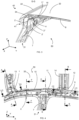
- FIG. 2 is a partial perspective view of a body of a vehicle, from the interior, according to one embodiment of the invention.
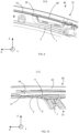
- FIG. 3 is a partial sectional view along a vertical and transverse plane of an arrangement according to one embodiment of the invention.
- FIG. 4 is a partial perspective view of a body of a vehicle, from the inside, according to a variant of the embodiment of the invention.
- THE figures 5, 6 , 7 and 8 are partial sectional views along vertical and transverse planes of the arrangement according to the variant of the embodiment.
- the direction in which the vehicle moves in a straight line is defined as the longitudinal direction X.
- the direction perpendicular to the longitudinal direction perpendicular to the other two, is called vertical direction Z.
- FIG. 1 illustrates a vehicle according to one embodiment, in particular a motor vehicle 20.
- the motor vehicle 20 comprises a body 30.
- the body 30 comprises a lateral structure on the left side and a lateral structure on the right side.
- the lateral structure 40 on the right side, respectively on the left side comprises a bay pillar lining 2 on the right side, respectively on the left side.
- Each bay post liner is generally covered with a corresponding bay post 22.
- each bay pillar lining extends on each side of a windshield 21 as well as towards the rear of the body 30.
- the lateral structure 40 on the right side, respectively on the left side also includes a lining of middle foot 7 right side, respectively left side.
- the lateral structure 40 on the right side, respectively on the left side further comprises a rear stretcher lining 5 on the right side, respectively on the left side.
- the bay pillar lining 2 extends beyond a middle leg 31 in the longitudinal or substantially longitudinal direction towards the rear of the body 30.
- the motor vehicle 20 further comprises an arrangement 50.
- the arrangement 50 comprises the lateral structure 40, a front roof cross member 9 and a central roof cross member 8.
- the front roof cross member 9 extends transversely or substantially transversely.
- the central roof crosspiece 8 also extends transversely or substantially transversely.
- the arrangement 50 comprises a first bracket 1.
- the first bracket 1 is fixed on the bay pillar lining 2 and on the front roof crosspiece 9.
- This arrangement preferably corresponds to the case of a motor vehicle 20 equipped with a roof or so-called “normal” roof, that is to say sheet metal 32.
- a roof is preferably devoid of glazed or glass part and preferably comprises sheet metal.
- the arrangement 50 also includes a second bracket 4.
- the second bracket 4 is fixed on the central roof crosspiece 8 and on the bay pillar lining 2 and on the middle leg lining 7.
- the side structure 40 also includes a lining rear stretcher 5.
- the rear stretcher lining 5 is fixed at a rear end 2R of the bay pillar lining 2.
- the arrangement 50 comprises a rear handle trigger guard 6.
- the bridge 6 allows the attachment of a handle allowing a rear passenger to stand, for example in the event of a turn, near the roof, for example above a rear window or a rear door frame.
- the rear handle trigger guard 6 is then fixed to the rear stretcher lining 5, for example by means of at least one rivet and/or welding.
- the bridge 6 is pre-positioned using two rivets before being welded.
- the arrangement 50 comprises a bridge 3 front handle on the right.
- the bridge 3 allows the attachment of a handle allowing a front passenger to hold, for example in the event of a turn, close to the roof, for example above the frame of the front passenger door.
- the front handle trigger guard 3 is located on the bay post lining 2 on the right side.
- the front handle trigger guard 3 is then fixed by means of at least one rivet and/or welding.
- the bridge 3 is pre-positioned using two rivets before being welded.
- the arrangement 50 comprises the lateral structure 40, a front roof crosspiece 13 and a central roof crosspiece 14.
- This variant preferably corresponds to a motor vehicle 20 equipped with a glass or glazed roof and/or or opening 33.
- the front roof crossbar 13, just like the roof crossbar central 14 extend transversely or substantially transversely.
- the lateral structure 40 comprises the middle leg lining 7, the rear stretcher lining 5 and the bay pillar lining 2.
- the arrangement 50 also includes the first bracket 1.
- the first bracket 1 is fixed on the bay pillar lining 2 and on the front roof crossbar 13.
- the arrangement 50 also includes a fourth bracket 12.
- the fourth bracket 12 is fixed on the rear stretcher lining 5 and on the central roof crossbar 14
- the arrangement 50 also comprises a third bracket 11.
- the third bracket 11 is fixed on the middle leg lining 7 and on the bay post lining 2.
- the third bracket 11 is thus intended to participate in the fixing. of the glass and/or opening roof 33.
- the arrangement 50 further comprises a support 10.
- the support 10 is intended to participate in the fixing of the glass and/or opening roof 33.
- the support 10 or lateral element can be put in place without consequence on the version with sheet metal roof 32.
- the bridge 3 can be arranged with a sheet metal roof 32 as well as a glass and/or opening roof 33.
- the support 10 is arranged on a rim 22' of the bay pillar 22.
- the support 10 or lateral connecting element of the fixed or opening glass roof 33 integrates the gluing track function.
- a gluing track that is to say a surface intended to receive glue, for example a bead of glue S, helping to hold the glazed part of the roof for example on the support 10, is provided.
- the gluing track can be used for fixing of a fixed glass roof glazing or for fixing a fixed side and front part of a sliding roof.
- the gluing track extends at the level of the third bracket 11 on the support 10, up to the central roof crosspiece 14.
- the gluing track can be used to attach glazing fixed glass roof or for fixing a fixed side and rear part of a sliding roof.
- a cross closure element 39 is then provided, arranged on the one hand on the first bracket 1 and on the other hand on the support 10.
- the cross closure element 39 just like the support 10, comes on the rim 22 ' of the bay amount 22.
- the first bracket 1 is geometrically designed to accept the extra thickness of the transom closure element 39.
- the first bracket 1 is also adapted .
- first bracket 1 and the second bracket 4 constitute interfaces facilitating the assembly of the front roof crosspiece 9 and the central roof crosspiece 8 with the bay pillar lining 2 in the case of the sheet metal roof 32.
- the arrangement 50 also includes a ring of reinforcements 34.
- This ring of reinforcements 34 comprises for example a front leg reinforcement and/or a front stretcher reinforcement and/or a middle leg reinforcement and/or a reinforcement of flap.
- the reinforcing ring 34 is arranged, arranged, on the top of an interior side edge 2' of the bay post lining 2.
- the reinforcing ring 34 is also fixed to the stretcher lining 5, in particular to the level of its vertical end part.
- the lower edge of the reinforcing ring 34 extends in a plane substantially identical to that of the stretcher lining 5 such that it is arranged to rest against an inner face of the stretcher lining, as is illustrated in the figure 8 .
- the first bracket 1 constitutes an interface facilitating the assembly of the front roof crosspiece 13 with the bay pillar lining 2.
- the fourth bracket 12 constitutes a interface facilitating the assembly of the central roof crosspiece 14 with the rear stretcher lining 5.
- the third bracket 11 constitutes an interface facilitating for example the assembly of the roof 33 with the bay pillar lining 2 and participating in maintaining the item 10.
- the rear stretcher liner 5 comprises a fixing interface intended to receive either the bridge 6 for fixing a grab handle for a rear passenger in the sheet metal roof version 32, or the fourth bracket 12 for fixing the cross member of the central roof 14 in fixed glass roof or opening roof version.
- the rear stretcher lining 5 can for example receive the trigger guard 6 and the fourth bracket 12 in the fixed or opening glass roof version.
- the bay post lining 2 has a more regular shape, having little or no protrusion.
- its 2" squares or edges, illustrated on the figures 3 , 5 , 6 And 7 are not impacted by geometric accidents, that is to say that there are no or very few changes in shape.
- regularity improves performance, notably stability and behavior in the event of an impact, particularly in the event of a frontal impact.
- the regularity of the bay post lining 2 facilitates the step of obtaining the bay post lining by stamping.
- geometric conformity in other words the adherence to the geometric targets of the bay pillar lining, is easily achieved.
- the bay pillar lining 2 is of great length in the longitudinal direction. In fact, the bay pillar lining 2 extends, towards the rear of the vehicle, beyond a middle foot 23. This helps to ensure structural continuity on the bay pillar line and to reduce the presence form accidents which could lead to instabilities, such as local buckling, during frontal impact loading. In addition, the ratio between the mass of material required for production and the mass of material actually used in the final bay pillar liner is optimal.
- first bracket 1, the bay pillar lining 2, the rear stretcher lining 5 and the middle leg lining 7 are identical regardless of the type of roof, namely fixed and/or opening glass 33 or sheet metal. 32.
- the diversity of the parts is reduced, the second, third and fourth attached brackets 4, 11, 12 being treated globally so as to only manage a single reference for the lining of the bay amount 2, rear stretcher lining 5, middle pillar lining 7 and first bracket 1 for connecting the front roof crossbar 9, 13.
- the stacking and installation of docking areas are treated accordingly.
- This standardization generates significant savings, particularly in terms of storage space for the bulky bay 2 post liners, which are now standard. Indeed, for the same vehicle model, it is enough to produce right bay pillar linings and left bay pillar linings, whatever its type of roof and whatever its steering side.
- the method comprises a step of supplying the first bracket 1, the rear stretcher lining 5 and the bay pillar lining 2.
- this step of fixing the bridge 3 is carried out in two stages. In fact, firstly the bridge 3 is pre-positioned using two rivets and secondly the bridge 3 is welded to the bay post lining 2.
- the method includes a step of supplying the second bracket 4 and the bridge 6 rear handle.
- this fixing step is carried out in two stages. Indeed, initially the second bracket 4 is pre-positioned using two rivets and secondly the second bracket 4 is welded to the bay upright lining 2. Likewise, initially the bridge 6 of rear handle is pre-positioned using two rivets and secondly the trigger guard 6 is welded to the rear stretcher lining 5 and, possibly, to the bay post lining 2.
- this fixing step is carried out by welding several thicknesses, by example of welding the thickness of the middle leg lining 7 with the thickness of the second bracket 4, possibly with the thickness of the bay upright lining 2, as illustrated in the Figure 3 .
- the method comprises a step of supplying the third bracket 11 and the fourth bracket 12.
- this fixing step is carried out in two stages. Indeed, initially the third bracket 11 is pre-positioned using two rivets and secondly the third bracket 11 is welded to the bay post lining 2. Likewise, initially the fourth bracket 12 is pre-positioned using two rivets and then the fourth bracket 12 is welded to the rear stretcher lining 5. Note that these pre-positionings using rivets require preliminary holes (not shown) for the passage of the rivets.
- this fixing step is carried out by welding several thicknesses, for example welding the thickness of the middle leg lining 7 with the thickness of the third bracket 11, possibly with the thickness of the bay upright lining 2, as illustrated in the figure 7 .
- the method preferably comprises a step of providing the ring of reinforcements 34.
- a step of fixing this ring of reinforcements 34 to the lateral structure 40 is preferably carried out by welding.
- the method also includes a step of providing a body side skin 41 illustrated in particular on the figures 3 And 8 .
- the body side skin 41 on the right side, respectively on the left side comprises the bay pillar 22 on the right side, respectively on the left side.
- a step of fixing this body side skin 41 to the lateral structure 40 is carried out by welding.
- the method also includes a step of supplying the support 10 intended to participate in fixing the glass and/or opening roof 33.
- a step of fixing the support 10 on the lateral structure 40 is carried out in two stages. Indeed, initially the support 10 is pre-positioned using two rivets and secondly the support 10 is welded to the lateral structure 40. Note that these pre-positionings by means of rivets require preliminary holes (not illustrated) for the passage of the rivets.
- the support 10 is preferably fixed on the body side skin 41, more precisely on the edge 22' of the bay post 22.
- a mode of execution of a method for obtaining the arrangement 50 of the body 30 of the motor vehicle 20 is described below.
- the method of obtaining the arrangement 50 comprises a step of implementing a method of obtaining the lateral structure 40.
- the crosspieces are advantageously simply placed on their respective brackets which naturally wedge them.
- At least one retention hook 17 is provided projecting from each bracket and is intended to be inserted into at least one orifice 18 on the corresponding crosspiece.
- the retention hooks 17 associated with the orifices 18 make it possible to avoid excessive movement of the crosspieces in the vertical direction. Such a movement could cause the sleepers to move out of their respective reception areas, in particular during possible conveying prior to fixing the sleepers.
- a step of fixing the central roof cross member 8, 14 placed on the second bracket 4 or on the fourth bracket 12 is provided prior to or following this step.
- the first bracket 1 is welded to the front roof crossbar 9, 13.
- the second bracket 4 or the fourth bracket 12 is welded to the corresponding central roof crossbar 8, 14.
Landscapes
- Engineering & Computer Science (AREA)
- Chemical & Material Sciences (AREA)
- Combustion & Propulsion (AREA)
- Transportation (AREA)
- Mechanical Engineering (AREA)
- Body Structure For Vehicles (AREA)
Claims (9)
- Anordnung (50), welche eine Seitenstruktur (40) eines Fahrzeugs, insbesondere eines Kraftfahrzeugs (20), einen vorderen Dachquerträger (9; 13) und einen mittleren Dachquerträger (8; 14) umfasst, wobei der vordere Dachquerträger (9; 13) und der mittlere Dachquerträger (8; 14) sich quer oder im Wesentlichen quer erstrecken, wobei die Seitenstruktur (40) eine Mittelsäulenverkleidung (7) und eine A-Säulenverkleidung (2) einer Fahrzeugkarosserie (30) umfasst, wobei die Anordnung (50) einen ersten Winkel (1) umfasst, der an der A-Säulenverkleidung (2) und am vorderen Dachquerträger (9; 13) befestigt ist, wobei sich die A-Säulenverkleidung (2) über eine Mittelsäule (31) hinaus zum hinteren Bereich einer solchen Karosserie (30) hin in der Längsrichtung oder im Wesentlichen in der Längsrichtung erstreckt, dadurch gekennzeichnet, dass die Anordnung (50) eine hintere Längsträgerverkleidung (5), die insbesondere an einem hinteren Ende (2R) der A-Säulenverkleidung (2) befestigt ist, und einen vierten Winkel (12), der an der hinteren Längsträgerverkleidung (5) und am mittleren Dachquerträger (14) befestigt ist, umfasst.
- Anordnung (50) nach dem vorhergehenden Anspruch, dadurch gekennzeichnet, dass die Anordnung (50) einen dritten Winkel (11) umfasst, der an der Mittelsäulenverkleidung (7) und an der A-Säulenverkleidung (2) befestigt ist, wobei der dritte Winkel (11) dazu bestimmt ist, zur Befestigung eines Glasdaches und/oder eines öffnungsfähigen Daches (33) beizutragen.
- Anordnung (50) nach Anspruch 1 oder 2, dadurch gekennzeichnet, dass die Anordnung (50) einen Träger (10) umfasst, der dazu bestimmt ist, zur Befestigung eines Glasdaches und/oder eines öffnungsfähigen Daches (33) beizutragen, insbesondere einen Träger (10), in den eine Klebebahn integriert ist.
- Anordnung (50) nach einem der vorhergehenden Ansprüche, dadurch gekennzeichnet, dass die Anordnung (50) einen hinteren Griffsteg (6) umfasst, der insbesondere an der hinteren Längsträgerverkleidung (5) durch mindestens einen Niet und/oder Schweißung befestigt ist.
- Anordnung (50) nach einem der vorhergehenden Ansprüche, dadurch gekennzeichnet, dass die Anordnung (50) einen vorderen Griffsteg (3) umfasst, der insbesondere an der A-Säulenverkleidung (2) durch mindestens einen Niet und/oder Schweißung befestigt ist.
- Fahrzeug, insbesondere Kraftfahrzeug (20), dadurch gekennzeichnet, dass es mindestens eine Anordnung (50) nach einem der vorhergehenden Ansprüche umfasst.
- Verfahren zur Herstellung einer Anordnung (50) nach einem der Ansprüche 2 bis 6,
dadurch gekennzeichnet, dass es einen Schritt der Bereitstellung eines ersten Winkels (1) der rechten Seite bzw. linken Seite, einer hinteren Längsträgerverkleidung (5) der rechten Seite bzw. linken Seite und einer der A-Säulenverkleidung (2) der rechten Seite bzw. linken Seite umfasst,gefolgt von einem Schritt der Befestigung des ersten Winkels (1) und der hinteren Längsträgerverkleidung (5) der A-Säulenverkleidung (2), insbesondere durch Schweißen, unddass im Falle des Vorhandenseins einer Linkslenkung bzw. Rechtslenkung eines solchen Fahrzeugs das Verfahren dann einen Schritt der Bereitstellung eines vorderen Griffstegs (3) der rechten Seite bzw. linken Seite umfasst, gefolgt von einem Schritt der Befestigung vorderen Griffstegs (3) an der A-Säulenverkleidung (2) der rechten Seite bzw. linken Seite, insbesondere durch mindestens einen Niet und/oder Schweißung. - Verfahren nach dem vorhergehenden Anspruch, dadurch gekennzeichnet, dass es einen Schritt der Bereitstellung eines dritten Winkels (11) und eines vierten Winkels (12) umfasst,
gefolgt von einem Schritt der Befestigung des dritten Winkels (11) an der A-Säulenverkleidung (2) und einem Schritt der Befestigung des vierten Winkels (12) an der hinteren Längsträgerverkleidung (5). - Verfahren nach dem vorhergehenden Anspruch, dadurch gekennzeichnet, dass der Schritt der Befestigung des dritten und des vierten Winkels (11, 12) in zwei Teilschritten durchgeführt wird, wobei in einem ersten Teilschritt der dritte und der vierte Winkel (11, 12) mithilfe von zwei Nieten vorpositioniert werden und in einem zweiten Teilschritt der dritte und der vierte Winkel (11, 12) an die A-Säulenverkleidung (2) bzw. an die hintere Längsträgerverkleidung (5) angeschweißt werden.
Applications Claiming Priority (2)
| Application Number | Priority Date | Filing Date | Title |
|---|---|---|---|
| FR1860186A FR3088049B1 (fr) | 2018-11-06 | 2018-11-06 | Procede d'obtention d'une caisse de vehicule |
| PCT/EP2019/080157 WO2020094597A1 (fr) | 2018-11-06 | 2019-11-05 | Procédé d'obtention d'une caisse de véhicule |
Publications (2)
| Publication Number | Publication Date |
|---|---|
| EP3877239A1 EP3877239A1 (de) | 2021-09-15 |
| EP3877239B1 true EP3877239B1 (de) | 2024-04-17 |
Family
ID=65685664
Family Applications (1)
| Application Number | Title | Priority Date | Filing Date |
|---|---|---|---|
| EP19795578.4A Active EP3877239B1 (de) | 2018-11-06 | 2019-11-05 | Anordnung mit einer seitenstruktur eines fahrzeugs und verfahren zur herstellung einer solchen anordnung |
Country Status (4)
| Country | Link |
|---|---|
| EP (1) | EP3877239B1 (de) |
| KR (1) | KR102711225B1 (de) |
| FR (1) | FR3088049B1 (de) |
| WO (1) | WO2020094597A1 (de) |
Family Cites Families (5)
| Publication number | Priority date | Publication date | Assignee | Title |
|---|---|---|---|---|
| FR2887843B1 (fr) * | 2005-06-30 | 2007-09-28 | Peugeot Citroen Automobiles Sa | Element de carrosserie pour la toiture d'un arc de pavillon et vehicule automobile comportant de tels elements de carrosserie |
| EP2752358B1 (de) * | 2011-08-31 | 2016-06-15 | Honda Motor Co., Ltd. | Oberer aufbau einer fahrzeugkarosserie |
| JP6128558B2 (ja) * | 2013-09-30 | 2017-05-17 | 株式会社Subaru | 車体上部構造 |
| JP6079743B2 (ja) * | 2014-10-15 | 2017-02-15 | トヨタ自動車株式会社 | 車両上部構造 |
| JP6481700B2 (ja) * | 2017-02-21 | 2019-03-13 | マツダ株式会社 | 車両の上部車体構造 |
-
2018
- 2018-11-06 FR FR1860186A patent/FR3088049B1/fr active Active
-
2019
- 2019-11-05 KR KR1020217017289A patent/KR102711225B1/ko active Active
- 2019-11-05 EP EP19795578.4A patent/EP3877239B1/de active Active
- 2019-11-05 WO PCT/EP2019/080157 patent/WO2020094597A1/fr not_active Ceased
Also Published As
| Publication number | Publication date |
|---|---|
| FR3088049B1 (fr) | 2020-10-23 |
| FR3088049A1 (fr) | 2020-05-08 |
| KR102711225B1 (ko) | 2024-09-27 |
| KR20210091214A (ko) | 2021-07-21 |
| WO2020094597A1 (fr) | 2020-05-14 |
| EP3877239A1 (de) | 2021-09-15 |
Similar Documents
| Publication | Publication Date | Title |
|---|---|---|
| EP2055614B1 (de) | Struktur eines Kraftfahrzeugs | |
| EP2586648B1 (de) | System, das eine Gleitschiene für einen Fahrzeugsitz umfasst, und Halterung zur Befestigung an dieser Gleitschiene sowie Herstellungsverfahren eines solchen Systems | |
| EP2091805B1 (de) | Mittelsäulenstruktur für kraftfahrzeug | |
| EP3877239B1 (de) | Anordnung mit einer seitenstruktur eines fahrzeugs und verfahren zur herstellung einer solchen anordnung | |
| FR2926056A1 (fr) | Pied avant renforce de vehicule. | |
| EP1234750A1 (de) | Aufbau für Kraftfahrzeug | |
| EP2072376B1 (de) | Verstärkte A-Säule eines Fahrzeugs | |
| EP2193064B1 (de) | Karosserieaufbau für ein fahrzeug | |
| EP1205377A1 (de) | Karosserieseitenteil für ein Kraftfahrzeug | |
| EP4257386A1 (de) | Fahrzeugkarosserieseite mit einem mittel zum halten einer schiebetür bei einem queraufprall aus dem fahrzeuginnenraum | |
| FR3139786A1 (fr) | extension de longeronnet pour véhicule automobile | |
| FR3138630A1 (fr) | Porte latérale comprenant un renfort de ceinture avec une encoche pour le fragiliser en cas de choc. | |
| FR2930511A1 (fr) | Structure de caisse d'un vehicule | |
| FR2934834A1 (fr) | Traverse de pavillon adaptee a differents configurations de toit d'un vehicule automobile | |
| EP4532299B1 (de) | Karosseriestruktur eines kraftfahrzeuges mit kontrollierter verformung des dachbogens bei einem frontalaufprall | |
| FR3051760A1 (fr) | Structure de pied milieu pourvu d'un element de renfort | |
| FR2983816A1 (fr) | Caisse de vehicule munie d'un renfort de doublure d'aile en y. | |
| FR3090556A1 (fr) | Renfort arrière supérieur de custode | |
| EP4077104B1 (de) | Strukturregal für ein kraftfahrzeug | |
| EP1862378B1 (de) | Kraftfahrzeug, das mit verbesserten Mitteln zur Begrenzung der lateralen Eindringmöglichkeiten bei seitlichem Aufprall auf das Kraftfahrzeug ausgestattet ist. | |
| FR3142435A1 (fr) | Pied milieu pour véhicule automobile et véhicule automobile comprenant un tel pied milieu | |
| FR3162186A1 (fr) | Véhicule pourvu d’un dispositif amélioré de fixation d’un enrouleur arrière de ceinture de sécurité a la caisse du véhicule | |
| FR2933369A1 (fr) | Chassis de vehicule automobile renforce | |
| WO2013060959A1 (fr) | Caisse de vehicule automobile et son brancard arriere avec toit trans | |
| FR3148767A1 (fr) | Pied avant de véhicule automobile comprenant un renfort et véhicule automobile comprenant un tel pied avant |
Legal Events
| Date | Code | Title | Description |
|---|---|---|---|
| STAA | Information on the status of an ep patent application or granted ep patent |
Free format text: STATUS: UNKNOWN |
|
| STAA | Information on the status of an ep patent application or granted ep patent |
Free format text: STATUS: THE INTERNATIONAL PUBLICATION HAS BEEN MADE |
|
| PUAI | Public reference made under article 153(3) epc to a published international application that has entered the european phase |
Free format text: ORIGINAL CODE: 0009012 |
|
| STAA | Information on the status of an ep patent application or granted ep patent |
Free format text: STATUS: REQUEST FOR EXAMINATION WAS MADE |
|
| 17P | Request for examination filed |
Effective date: 20210504 |
|
| AK | Designated contracting states |
Kind code of ref document: A1 Designated state(s): AL AT BE BG CH CY CZ DE DK EE ES FI FR GB GR HR HU IE IS IT LI LT LU LV MC MK MT NL NO PL PT RO RS SE SI SK SM TR |
|
| DAV | Request for validation of the european patent (deleted) | ||
| DAX | Request for extension of the european patent (deleted) | ||
| RAP3 | Party data changed (applicant data changed or rights of an application transferred) |
Owner name: RENAULT S.A.S |
|
| RAP3 | Party data changed (applicant data changed or rights of an application transferred) |
Owner name: RENAULT S.A.S |
|
| P01 | Opt-out of the competence of the unified patent court (upc) registered |
Effective date: 20230608 |
|
| GRAP | Despatch of communication of intention to grant a patent |
Free format text: ORIGINAL CODE: EPIDOSNIGR1 |
|
| STAA | Information on the status of an ep patent application or granted ep patent |
Free format text: STATUS: GRANT OF PATENT IS INTENDED |
|
| INTG | Intention to grant announced |
Effective date: 20231114 |
|
| GRAS | Grant fee paid |
Free format text: ORIGINAL CODE: EPIDOSNIGR3 |
|
| GRAA | (expected) grant |
Free format text: ORIGINAL CODE: 0009210 |
|
| STAA | Information on the status of an ep patent application or granted ep patent |
Free format text: STATUS: THE PATENT HAS BEEN GRANTED |
|
| AK | Designated contracting states |
Kind code of ref document: B1 Designated state(s): AL AT BE BG CH CY CZ DE DK EE ES FI FR GB GR HR HU IE IS IT LI LT LU LV MC MK MT NL NO PL PT RO RS SE SI SK SM TR |
|
| REG | Reference to a national code |
Ref country code: GB Ref legal event code: FG4D Free format text: NOT ENGLISH |
|
| REG | Reference to a national code |
Ref country code: CH Ref legal event code: EP |
|
| REG | Reference to a national code |
Ref country code: IE Ref legal event code: FG4D Free format text: LANGUAGE OF EP DOCUMENT: FRENCH Ref country code: DE Ref legal event code: R096 Ref document number: 602019050520 Country of ref document: DE |
|
| REG | Reference to a national code |
Ref country code: LT Ref legal event code: MG9D |
|
| REG | Reference to a national code |
Ref country code: NL Ref legal event code: MP Effective date: 20240417 |
|
| REG | Reference to a national code |
Ref country code: AT Ref legal event code: MK05 Ref document number: 1677004 Country of ref document: AT Kind code of ref document: T Effective date: 20240417 |
|
| PG25 | Lapsed in a contracting state [announced via postgrant information from national office to epo] |
Ref country code: NL Free format text: LAPSE BECAUSE OF FAILURE TO SUBMIT A TRANSLATION OF THE DESCRIPTION OR TO PAY THE FEE WITHIN THE PRESCRIBED TIME-LIMIT Effective date: 20240417 |
|
| PG25 | Lapsed in a contracting state [announced via postgrant information from national office to epo] |
Ref country code: NL Free format text: LAPSE BECAUSE OF FAILURE TO SUBMIT A TRANSLATION OF THE DESCRIPTION OR TO PAY THE FEE WITHIN THE PRESCRIBED TIME-LIMIT Effective date: 20240417 |
|
| PG25 | Lapsed in a contracting state [announced via postgrant information from national office to epo] |
Ref country code: IS Free format text: LAPSE BECAUSE OF FAILURE TO SUBMIT A TRANSLATION OF THE DESCRIPTION OR TO PAY THE FEE WITHIN THE PRESCRIBED TIME-LIMIT Effective date: 20240817 |
|
| PG25 | Lapsed in a contracting state [announced via postgrant information from national office to epo] |
Ref country code: BG Free format text: LAPSE BECAUSE OF FAILURE TO SUBMIT A TRANSLATION OF THE DESCRIPTION OR TO PAY THE FEE WITHIN THE PRESCRIBED TIME-LIMIT Effective date: 20240417 |
|
| PG25 | Lapsed in a contracting state [announced via postgrant information from national office to epo] |
Ref country code: HR Free format text: LAPSE BECAUSE OF FAILURE TO SUBMIT A TRANSLATION OF THE DESCRIPTION OR TO PAY THE FEE WITHIN THE PRESCRIBED TIME-LIMIT Effective date: 20240417 Ref country code: FI Free format text: LAPSE BECAUSE OF FAILURE TO SUBMIT A TRANSLATION OF THE DESCRIPTION OR TO PAY THE FEE WITHIN THE PRESCRIBED TIME-LIMIT Effective date: 20240417 |
|
| PG25 | Lapsed in a contracting state [announced via postgrant information from national office to epo] |
Ref country code: GR Free format text: LAPSE BECAUSE OF FAILURE TO SUBMIT A TRANSLATION OF THE DESCRIPTION OR TO PAY THE FEE WITHIN THE PRESCRIBED TIME-LIMIT Effective date: 20240718 |
|
| PG25 | Lapsed in a contracting state [announced via postgrant information from national office to epo] |
Ref country code: PT Free format text: LAPSE BECAUSE OF FAILURE TO SUBMIT A TRANSLATION OF THE DESCRIPTION OR TO PAY THE FEE WITHIN THE PRESCRIBED TIME-LIMIT Effective date: 20240819 |
|
| PG25 | Lapsed in a contracting state [announced via postgrant information from national office to epo] |
Ref country code: ES Free format text: LAPSE BECAUSE OF FAILURE TO SUBMIT A TRANSLATION OF THE DESCRIPTION OR TO PAY THE FEE WITHIN THE PRESCRIBED TIME-LIMIT Effective date: 20240417 |
|
| PG25 | Lapsed in a contracting state [announced via postgrant information from national office to epo] |
Ref country code: AT Free format text: LAPSE BECAUSE OF FAILURE TO SUBMIT A TRANSLATION OF THE DESCRIPTION OR TO PAY THE FEE WITHIN THE PRESCRIBED TIME-LIMIT Effective date: 20240417 |
|
| PG25 | Lapsed in a contracting state [announced via postgrant information from national office to epo] |
Ref country code: PL Free format text: LAPSE BECAUSE OF FAILURE TO SUBMIT A TRANSLATION OF THE DESCRIPTION OR TO PAY THE FEE WITHIN THE PRESCRIBED TIME-LIMIT Effective date: 20240417 |
|
| PG25 | Lapsed in a contracting state [announced via postgrant information from national office to epo] |
Ref country code: LV Free format text: LAPSE BECAUSE OF FAILURE TO SUBMIT A TRANSLATION OF THE DESCRIPTION OR TO PAY THE FEE WITHIN THE PRESCRIBED TIME-LIMIT Effective date: 20240417 |
|
| PG25 | Lapsed in a contracting state [announced via postgrant information from national office to epo] |
Ref country code: PT Free format text: LAPSE BECAUSE OF FAILURE TO SUBMIT A TRANSLATION OF THE DESCRIPTION OR TO PAY THE FEE WITHIN THE PRESCRIBED TIME-LIMIT Effective date: 20240819 Ref country code: PL Free format text: LAPSE BECAUSE OF FAILURE TO SUBMIT A TRANSLATION OF THE DESCRIPTION OR TO PAY THE FEE WITHIN THE PRESCRIBED TIME-LIMIT Effective date: 20240417 Ref country code: NO Free format text: LAPSE BECAUSE OF FAILURE TO SUBMIT A TRANSLATION OF THE DESCRIPTION OR TO PAY THE FEE WITHIN THE PRESCRIBED TIME-LIMIT Effective date: 20240717 Ref country code: LV Free format text: LAPSE BECAUSE OF FAILURE TO SUBMIT A TRANSLATION OF THE DESCRIPTION OR TO PAY THE FEE WITHIN THE PRESCRIBED TIME-LIMIT Effective date: 20240417 Ref country code: IS Free format text: LAPSE BECAUSE OF FAILURE TO SUBMIT A TRANSLATION OF THE DESCRIPTION OR TO PAY THE FEE WITHIN THE PRESCRIBED TIME-LIMIT Effective date: 20240817 Ref country code: HR Free format text: LAPSE BECAUSE OF FAILURE TO SUBMIT A TRANSLATION OF THE DESCRIPTION OR TO PAY THE FEE WITHIN THE PRESCRIBED TIME-LIMIT Effective date: 20240417 Ref country code: GR Free format text: LAPSE BECAUSE OF FAILURE TO SUBMIT A TRANSLATION OF THE DESCRIPTION OR TO PAY THE FEE WITHIN THE PRESCRIBED TIME-LIMIT Effective date: 20240718 Ref country code: FI Free format text: LAPSE BECAUSE OF FAILURE TO SUBMIT A TRANSLATION OF THE DESCRIPTION OR TO PAY THE FEE WITHIN THE PRESCRIBED TIME-LIMIT Effective date: 20240417 Ref country code: ES Free format text: LAPSE BECAUSE OF FAILURE TO SUBMIT A TRANSLATION OF THE DESCRIPTION OR TO PAY THE FEE WITHIN THE PRESCRIBED TIME-LIMIT Effective date: 20240417 Ref country code: BG Free format text: LAPSE BECAUSE OF FAILURE TO SUBMIT A TRANSLATION OF THE DESCRIPTION OR TO PAY THE FEE WITHIN THE PRESCRIBED TIME-LIMIT Effective date: 20240417 Ref country code: AT Free format text: LAPSE BECAUSE OF FAILURE TO SUBMIT A TRANSLATION OF THE DESCRIPTION OR TO PAY THE FEE WITHIN THE PRESCRIBED TIME-LIMIT Effective date: 20240417 Ref country code: RS Free format text: LAPSE BECAUSE OF FAILURE TO SUBMIT A TRANSLATION OF THE DESCRIPTION OR TO PAY THE FEE WITHIN THE PRESCRIBED TIME-LIMIT Effective date: 20240717 |
|
| PG25 | Lapsed in a contracting state [announced via postgrant information from national office to epo] |
Ref country code: DK Free format text: LAPSE BECAUSE OF FAILURE TO SUBMIT A TRANSLATION OF THE DESCRIPTION OR TO PAY THE FEE WITHIN THE PRESCRIBED TIME-LIMIT Effective date: 20240417 |
|
| REG | Reference to a national code |
Ref country code: DE Ref legal event code: R097 Ref document number: 602019050520 Country of ref document: DE |
|
| PG25 | Lapsed in a contracting state [announced via postgrant information from national office to epo] |
Ref country code: EE Free format text: LAPSE BECAUSE OF FAILURE TO SUBMIT A TRANSLATION OF THE DESCRIPTION OR TO PAY THE FEE WITHIN THE PRESCRIBED TIME-LIMIT Effective date: 20240417 |
|
| PG25 | Lapsed in a contracting state [announced via postgrant information from national office to epo] |
Ref country code: CZ Free format text: LAPSE BECAUSE OF FAILURE TO SUBMIT A TRANSLATION OF THE DESCRIPTION OR TO PAY THE FEE WITHIN THE PRESCRIBED TIME-LIMIT Effective date: 20240417 |
|
| PG25 | Lapsed in a contracting state [announced via postgrant information from national office to epo] |
Ref country code: SK Free format text: LAPSE BECAUSE OF FAILURE TO SUBMIT A TRANSLATION OF THE DESCRIPTION OR TO PAY THE FEE WITHIN THE PRESCRIBED TIME-LIMIT Effective date: 20240417 Ref country code: RO Free format text: LAPSE BECAUSE OF FAILURE TO SUBMIT A TRANSLATION OF THE DESCRIPTION OR TO PAY THE FEE WITHIN THE PRESCRIBED TIME-LIMIT Effective date: 20240417 |
|
| PG25 | Lapsed in a contracting state [announced via postgrant information from national office to epo] |
Ref country code: SM Free format text: LAPSE BECAUSE OF FAILURE TO SUBMIT A TRANSLATION OF THE DESCRIPTION OR TO PAY THE FEE WITHIN THE PRESCRIBED TIME-LIMIT Effective date: 20240417 |
|
| PG25 | Lapsed in a contracting state [announced via postgrant information from national office to epo] |
Ref country code: SM Free format text: LAPSE BECAUSE OF FAILURE TO SUBMIT A TRANSLATION OF THE DESCRIPTION OR TO PAY THE FEE WITHIN THE PRESCRIBED TIME-LIMIT Effective date: 20240417 Ref country code: SK Free format text: LAPSE BECAUSE OF FAILURE TO SUBMIT A TRANSLATION OF THE DESCRIPTION OR TO PAY THE FEE WITHIN THE PRESCRIBED TIME-LIMIT Effective date: 20240417 Ref country code: RO Free format text: LAPSE BECAUSE OF FAILURE TO SUBMIT A TRANSLATION OF THE DESCRIPTION OR TO PAY THE FEE WITHIN THE PRESCRIBED TIME-LIMIT Effective date: 20240417 Ref country code: EE Free format text: LAPSE BECAUSE OF FAILURE TO SUBMIT A TRANSLATION OF THE DESCRIPTION OR TO PAY THE FEE WITHIN THE PRESCRIBED TIME-LIMIT Effective date: 20240417 Ref country code: DK Free format text: LAPSE BECAUSE OF FAILURE TO SUBMIT A TRANSLATION OF THE DESCRIPTION OR TO PAY THE FEE WITHIN THE PRESCRIBED TIME-LIMIT Effective date: 20240417 Ref country code: CZ Free format text: LAPSE BECAUSE OF FAILURE TO SUBMIT A TRANSLATION OF THE DESCRIPTION OR TO PAY THE FEE WITHIN THE PRESCRIBED TIME-LIMIT Effective date: 20240417 |
|
| PG25 | Lapsed in a contracting state [announced via postgrant information from national office to epo] |
Ref country code: IT Free format text: LAPSE BECAUSE OF FAILURE TO SUBMIT A TRANSLATION OF THE DESCRIPTION OR TO PAY THE FEE WITHIN THE PRESCRIBED TIME-LIMIT Effective date: 20240417 |
|
| PLBE | No opposition filed within time limit |
Free format text: ORIGINAL CODE: 0009261 |
|
| STAA | Information on the status of an ep patent application or granted ep patent |
Free format text: STATUS: NO OPPOSITION FILED WITHIN TIME LIMIT |
|
| 26N | No opposition filed |
Effective date: 20250120 |
|
| PG25 | Lapsed in a contracting state [announced via postgrant information from national office to epo] |
Ref country code: SI Free format text: LAPSE BECAUSE OF FAILURE TO SUBMIT A TRANSLATION OF THE DESCRIPTION OR TO PAY THE FEE WITHIN THE PRESCRIBED TIME-LIMIT Effective date: 20240417 |
|
| REG | Reference to a national code |
Ref country code: CH Ref legal event code: PL |
|
| PG25 | Lapsed in a contracting state [announced via postgrant information from national office to epo] |
Ref country code: MC Free format text: LAPSE BECAUSE OF FAILURE TO SUBMIT A TRANSLATION OF THE DESCRIPTION OR TO PAY THE FEE WITHIN THE PRESCRIBED TIME-LIMIT Effective date: 20240417 |
|
| PG25 | Lapsed in a contracting state [announced via postgrant information from national office to epo] |
Ref country code: LU Free format text: LAPSE BECAUSE OF NON-PAYMENT OF DUE FEES Effective date: 20241105 |
|
| REG | Reference to a national code |
Ref country code: CH Ref legal event code: PL |
|
| PG25 | Lapsed in a contracting state [announced via postgrant information from national office to epo] |
Ref country code: CH Free format text: LAPSE BECAUSE OF NON-PAYMENT OF DUE FEES Effective date: 20241130 |
|
| REG | Reference to a national code |
Ref country code: BE Ref legal event code: MM Effective date: 20241130 |
|
| PG25 | Lapsed in a contracting state [announced via postgrant information from national office to epo] |
Ref country code: SE Free format text: LAPSE BECAUSE OF FAILURE TO SUBMIT A TRANSLATION OF THE DESCRIPTION OR TO PAY THE FEE WITHIN THE PRESCRIBED TIME-LIMIT Effective date: 20240417 |
|
| PG25 | Lapsed in a contracting state [announced via postgrant information from national office to epo] |
Ref country code: BE Free format text: LAPSE BECAUSE OF NON-PAYMENT OF DUE FEES Effective date: 20241130 |
|
| PG25 | Lapsed in a contracting state [announced via postgrant information from national office to epo] |
Ref country code: IE Free format text: LAPSE BECAUSE OF NON-PAYMENT OF DUE FEES Effective date: 20241105 |
|
| PGFP | Annual fee paid to national office [announced via postgrant information from national office to epo] |
Ref country code: DE Payment date: 20251119 Year of fee payment: 7 |
|
| PGFP | Annual fee paid to national office [announced via postgrant information from national office to epo] |
Ref country code: GB Payment date: 20251121 Year of fee payment: 7 |
|
| PGFP | Annual fee paid to national office [announced via postgrant information from national office to epo] |
Ref country code: FR Payment date: 20251126 Year of fee payment: 7 |
|
| PG25 | Lapsed in a contracting state [announced via postgrant information from national office to epo] |
Ref country code: HU Free format text: LAPSE BECAUSE OF FAILURE TO SUBMIT A TRANSLATION OF THE DESCRIPTION OR TO PAY THE FEE WITHIN THE PRESCRIBED TIME-LIMIT; INVALID AB INITIO Effective date: 20191105 |
|
| PG25 | Lapsed in a contracting state [announced via postgrant information from national office to epo] |
Ref country code: CY Free format text: LAPSE BECAUSE OF FAILURE TO SUBMIT A TRANSLATION OF THE DESCRIPTION OR TO PAY THE FEE WITHIN THE PRESCRIBED TIME-LIMIT; INVALID AB INITIO Effective date: 20191105 |