EP3885666B1 - Dispositif d'arrêt destiné à être utilisé dans une conduite d'air d'une installation technique de ventilation ou d'une installation de désenfumage mécanique - Google Patents
Dispositif d'arrêt destiné à être utilisé dans une conduite d'air d'une installation technique de ventilation ou d'une installation de désenfumage mécanique Download PDFInfo
- Publication number
- EP3885666B1 EP3885666B1 EP20165682.4A EP20165682A EP3885666B1 EP 3885666 B1 EP3885666 B1 EP 3885666B1 EP 20165682 A EP20165682 A EP 20165682A EP 3885666 B1 EP3885666 B1 EP 3885666B1
- Authority
- EP
- European Patent Office
- Prior art keywords
- shutoff valve
- valve according
- coating
- panel
- housing
- Prior art date
- Legal status (The legal status is an assumption and is not a legal conclusion. Google has not performed a legal analysis and makes no representation as to the accuracy of the status listed.)
- Active
Links
Images


Classifications
-
- F—MECHANICAL ENGINEERING; LIGHTING; HEATING; WEAPONS; BLASTING
- F24—HEATING; RANGES; VENTILATING
- F24F—AIR-CONDITIONING; AIR-HUMIDIFICATION; VENTILATION; USE OF AIR CURRENTS FOR SCREENING
- F24F13/00—Details common to, or for air-conditioning, air-humidification, ventilation or use of air currents for screening
- F24F13/08—Air-flow control members, e.g. louvres, grilles, flaps or guide plates
- F24F13/10—Air-flow control members, e.g. louvres, grilles, flaps or guide plates movable, e.g. dampers
- F24F13/14—Air-flow control members, e.g. louvres, grilles, flaps or guide plates movable, e.g. dampers built up of tilting members, e.g. louvre
- F24F13/1426—Air-flow control members, e.g. louvres, grilles, flaps or guide plates movable, e.g. dampers built up of tilting members, e.g. louvre characterised by actuating means
-
- A—HUMAN NECESSITIES
- A62—LIFE-SAVING; FIRE-FIGHTING
- A62C—FIRE-FIGHTING
- A62C2/00—Fire prevention or containment
- A62C2/06—Physical fire-barriers
- A62C2/12—Hinged dampers
-
- F—MECHANICAL ENGINEERING; LIGHTING; HEATING; WEAPONS; BLASTING
- F24—HEATING; RANGES; VENTILATING
- F24F—AIR-CONDITIONING; AIR-HUMIDIFICATION; VENTILATION; USE OF AIR CURRENTS FOR SCREENING
- F24F11/00—Control or safety arrangements
- F24F11/30—Control or safety arrangements for purposes related to the operation of the system, e.g. for safety or monitoring
- F24F11/32—Responding to malfunctions or emergencies
- F24F11/33—Responding to malfunctions or emergencies to fire, excessive heat or smoke
- F24F11/35—Responding to malfunctions or emergencies to fire, excessive heat or smoke by closing air passages
-
- F—MECHANICAL ENGINEERING; LIGHTING; HEATING; WEAPONS; BLASTING
- F24—HEATING; RANGES; VENTILATING
- F24F—AIR-CONDITIONING; AIR-HUMIDIFICATION; VENTILATION; USE OF AIR CURRENTS FOR SCREENING
- F24F13/00—Details common to, or for air-conditioning, air-humidification, ventilation or use of air currents for screening
- F24F13/08—Air-flow control members, e.g. louvres, grilles, flaps or guide plates
- F24F13/10—Air-flow control members, e.g. louvres, grilles, flaps or guide plates movable, e.g. dampers
- F24F13/14—Air-flow control members, e.g. louvres, grilles, flaps or guide plates movable, e.g. dampers built up of tilting members, e.g. louvre
Definitions
- the invention relates to a shut-off device for use in an air duct of a ventilation system or a mechanical smoke extraction system, wherein the shut-off device comprises a housing, preferably having a square cross-section, through which a gaseous medium flows, with a housing wall and a damper blade pivotably mounted in the housing about a pivot axis.
- shut-off devices In their closed position, shut-off devices are intended to close the flow cross-section of the air duct and prevent the gaseous medium from flowing. If the shut-off device is designed as a fire damper, the damper blade is made of calcium silicate. Although corresponding shut-off devices can be used in air ducts for the ventilation of living or working spaces, for example, they cannot be used in atmospheres that have a damaging and/or corrosive effect on the shut-off device due to chemical reactions, either planned or unplanned, as the areas of the shut-off device that are in contact with the medium flowing in the housing are attacked by a chemically aggressive gaseous medium.
- the object of the invention is to avoid the above-mentioned disadvantages and to provide a shut-off device which also works in atmospheres which are planned or can be used unscheduled due to chemical reactions which have a damaging effect on the shut-off device and/or cause corrosion of metallic and non-metallic materials.
- shut-off device for use of the shut-off device in connection with a chemically aggressive gaseous medium, at least all areas of the shut-off device that are in contact with the medium flowing in the housing are designed to be resistant to damaging chemical reactions with this medium or due to this medium, wherein the resistance is formed by a coating applied to the areas that come into contact with the flowing medium.
- the pivot axis can be formed by a fixed axis or by a shaft that is rotationally fixed relative to the flap blade.
- the axis or the shaft can be Teflon-coated, for example.
- the shut-off device according to the invention therefore has no metallic surfaces, at least in the areas that are in contact with the medium flowing in the housing.
- a chemically aggressive gaseous medium is understood to mean, for example, contaminated and aggressive exhaust air from laboratories and laboratory fume hoods, from the chemical industry, from electroplating or from the automotive industry.
- This exhaust air can be chemically contaminated with a wide variety of substances, some of which are very aggressive, such as acids or bases. However, it can also be exhaust air from commercial kitchens.
- a coating applied to the areas that come into contact with the flowing medium prevents the areas that come into contact with the flowing medium from being attacked by the chemically aggressive gaseous medium. All areas of the shut-off device that are in contact with the medium flowing in the housing are thus resistant to the atmosphere prevailing in the shut-off device. As a result of the resistance, a chemical reaction initiated by the chemically aggressive gaseous medium is prevented, or at least reduced to a minimum, so that the shut-off device according to the invention, which is for example a fire damper, can be used safely for just as long as a conventional shut-off device designed as a fire damper in an air duct for the ventilation of, for example, living or working spaces.
- all areas refers to the areas/components of the shut-off device that come into contact with the flowing medium and that are relevant to the function of the shut-off device. These are, for example, the inside of the housing wall, the flap blade, the bearing or the like. However, it can also be the outside(s) of the shut-off device, which is (are) used in a laboratory room, for example.
- the flap can be made of calcium silicate, for example a calcium silicate plate, or of metal. All areas of the flap surface that come into contact with the flowing medium are provided with the coating according to the invention.
- the applied coating can also provide additional protection against mechanical stress.
- the flowing medium can contain particles that have an abrasive effect on areas of the shut-off device located inside the housing.
- the coating applied to the areas that come into contact with the flowing medium means that the shut-off device can also be used in atmospheres with a high particle content, for example.
- a two-component or multi-component epoxy resin coating can be used as the coating.
- This type of coating is suitable for use in very aggressive chemical media.
- Such a two-component epoxy resin coating is available, for example, under the name Sikafloor ® -381.
- this type of coating offers good surface protection (mechanical resilience) and hardens quickly.
- the coating can be solvent-free when cured.
- the coating can be ceramic-reinforced.
- a two-component epoxy resin coating is available under the name LOCTITE ® PC 7255 TM .
- Such a coating ensures good protection of surfaces even in very aggressive chemical media. Since the coating is ceramic-reinforced, the surface coated is not only well protected against corrosive substances, but also against abrasive substances.
- the coating can be sprayed on. Alternatively, the coating can be applied mechanically.
- Calcium silicate has a very uneven and rough surface. Calcium silicate also absorbs liquids very well.
- the surface of a calcium silicate board for example, is sealed at least to a large extent, preferably completely, so that only a small amount of the coating needs to be applied.
- the primer also improves the adhesion of the coating that is subsequently applied.
- At least a portion of the housing wall can be made of at least one fire protection board or at least one cement-bonded calcium silicate board.
- the thickness of the housing wall can preferably be between 10 mm and 80 mm If the housing has a square cross-section, the housing wall consists of four housing wall sections that are fixed to one another. Each housing wall section can be made of a fire protection board or a cement-bonded calcium silicate board, for example. Of course, other materials that are sufficiently temperature-resistant are also conceivable.
- the damper blade can be made of at least one fire protection board or a cement-bonded calcium silicate board. Of course, other materials that are sufficiently temperature-resistant are also conceivable.
- the shut-off device can be designed as a smoke extraction flap.
- Smoke extraction flaps are used to keep areas of a building, for example an escape area, smoke-free.
- the application area of a smoke extraction flap is at a temperature that lies between the ambient temperature of the building area to be kept smoke-free (cold smoke extraction) and a temperature of up to 1000°C or more (hot smoke extraction).
- smoke extraction flaps must ensure both cold sealing and hot sealing. Due to the potentially high temperatures, the housing, flap, stops and the encapsulation of the drive device arranged on the outside of the housing are usually made of calcium silicate.
- Smoke extraction flaps are usually triggered by a smoke detector.
- triggering devices such as a manual triggering device, a remote triggering device, a fire alarm system, a coupler or the like.
- the energy for opening and closing must be permanently available to the shut-off device.
- Smoke extraction dampers are designed in such a way that even after they have been triggered, ie after they have been swung from the open position to the closed position, they can still be opened, ie swung into the open position. This also applies in the opposite case.
- the shut-off device can also be designed as a fire damper.
- Fire dampers usually have a housing made of metal or calcium silicate plates in which a damper blade made of calcium silicate is pivotably mounted.
- a fire damper can, for example, be manually operated.
- an actuating element such as an actuating handle, is usually provided, preferably arranged on the outside of the housing.
- the damper blade can be fixed in its open position by means of a fixing device against a restoring force and can be pivoted from the fixed position into its closed position by the restoring force after the fixing device has been released, for example in the event of a fire.
- the restoring force can be generated by a spring, preferably arranged outside the housing.
- the fixing device is designed, for example, as a fusible link.
- the damper blade is fixed in its open position by means of the fixing device against a restoring force. For example, in the event of a fire, i.e.
- the damper blade when the temperature exceeds a value of approximately 72°C, the damper blade is pivoted from its fixed open position into its closed position by the restoring force provided by the spring after the fixing device, for example the fusible link, has been triggered.
- an intumescent material i.e. a material that foams when heated, inflates.
- the intumescent material now completely fills any gap that may still exist, for example between the housing and the flap in its closed position. The flap can no longer be opened and must be replaced later.
- fixing devices such as a thermoelectric triggering device.
- shut-off device can also be designed as a combined fire protection and smoke extraction damper.
- the drive device is designed as a spring return motor, for example.
- a spring in the spring return motor is tensioned.
- a thermoelectric trigger device which can be an electrical fusible link, for example, causes a voltage interruption.
- the spring return motor can then no longer counteract the restoring force generated by the tensioned spring, so that the damper blade is closed by the restoring force applied by the spring.
- an OPEN/CLOSE drive can be used as a drive device for opening and closing the damper blade.
- the OPEN/CLOSE drive provides a maximum torque of 40 Nm.
- the limit switches for the OPEN and CLOSED position indicators are usually located inside the OPEN/CLOSE drive.
- the OPEN/CLOSE drive is controlled via a suitable interface monitoring unit with a control module.
- the interface monitoring unit supplies the OPEN/CLOSE drive with voltage and monitors when the safety position is reached. It also guarantees that the damper blade closes if there is a voltage drop in a building.
- the OPEN/CLOSE drive is controlled via a control module, for example. If the control module includes double-layer capacitors, the double-layer capacitors provide a redundant 24 V power supply.
- thermoelectric trigger element can be connected to an input of the control module in a wire-break-proof manner. In the event of a thermal trigger, the control module closes the damper blade. If the 24V power supply is interrupted, the energy from the double-layer capacitors also closes the damper blade.
- the control module is preferably located within an enclosure of the OPEN/CLOSE drive and is connected to a controller unit using, for example, two-wire technology.
- the controller unit consists of a controller including suitable control software and a suitable AS interface. Power supply unit for communication with the control module.
- the protocol that exchanges data between the control module and the controller has been internationally standardized since 1999 according to EN 50295 and IEC 62026-2.
- the data transmission and the power supply for controlling the OPEN/CLOSE drive are carried out via a two-wire cable, for example.
- a two-wire cable for example.
- both the position and the running time of the damper blade can be monitored.
- the control module can also be used as a "stand-alone variant". In this case, communication with the controller is not necessary.
- the manual opening and closing of the damper blade takes place via an input contact on the control module.
- a smoke extraction damper comprises a motorized drive device
- an applied voltage is required both for pivoting the damper blade from the open position to its closed position and for pivoting the damper blade from the closed position to its open position.
- At least one screw preferably passing through the pivot axis, can be provided for the rotationally fixed fastening of the damper blade relative to the pivot axis.
- a receptacle preferably a receptacle designed as a milling, can be provided in at least one surface of the damper blade for receiving the end of the screw located in the region of this surface of the damper blade.
- At least one receptacle can be closed with a cover, preferably attached to the flap leaf by means of screws.
- the cover can be a calcium silicate plate, for example. In such a design, the coating also covers the cover.
- the shut-off device can comprise an energy storage device. This can be, for example, a battery or an accumulator.
- the energy storage device can also be designed as a capacitor that is charged when voltage is applied. If, for example, an electrically operated drive device is provided, the damper blade can be pivoted from the open position to its closed position or vice versa from the closed position to its open position even if the voltage is interrupted.
- the figures show a shut-off device with a housing 2 having a surrounding housing wall 1.
- the housing 2 has a square cross-sectional area.
- the housing wall 1 thus consists of a total of four housing wall sections, which are fixed to one another, for example, by means of screws (not shown).
- a flap 5 is provided in the housing 2, which is pivotably mounted about a pivot axis 3 in the direction of the arrow 4.
- the pivot axis 3 is arranged centrally with respect to the flap 5.
- a seal (not shown) is provided between the flap 5 and the housing wall 1.
- the flap blade 5 is fixed in a rotationally fixed manner relative to the pivot axis 3.
- the screw 16 passes through the pivot axis 3.
- the shut-off device is designed as a fire damper.
- Both the housing wall 1 of the housing 2 and the damper blade 5 are made of calcium silicate plates.
- shut-off device is also suitable for influencing the flow of chemically aggressive gaseous media and can therefore be used, for example, in an exhaust air duct in a laboratory or a laboratory fume hood. It is of course also possible to use it in ventilation ducts in commercial kitchens, for example as a kitchen exhaust air flap.
- a stop 7 is provided on the inside of the housing 2 both in front of and behind the pivot axis 3.
- the stops 7 with their coating 17 applied on both sides are offset from one another in the direction of flow 6 by approximately the thickness of the flap blade 5, which has the coating 17 on all sides, and are arranged on opposite sides of the housing 2 and are fastened to the adjacent housing wall 1 by means of screws concealed by the coating 17.
- Each stop 7 is approximately U-shaped and consists of a base section 8 which is arranged parallel to the pivot axis 3.
- a side section 9 adjoins both ends of each base section 8. The length of each side section 9 is adjusted so that in the open position the flap blade 5 is aligned parallel to the flow direction 6. In this position the flap blade 5 can touch all four free ends of the side sections 9. In such a configuration, the four ends of the side sections 9 define the open position of the flap leaf 5.
- each stop 7 has a recess 10 on the side facing the flap leaf 5 in its closed position, which recess 10 has a square cross-section in the embodiment shown.
- Each recess 10 is formed by a projecting area 11 of the stop 7 and by the adjacent housing wall 1.
- a seal 12 is provided in the recess 10 which completely fills the recess 10 and also protrudes from the recess 10 and thus protrudes from the stop 7.
- Each recess 10 extends over the entire length of the base section 8 and the two side sections 9 of the respective stop 7. The areas of the seal 12 which come into contact with the flowing medium are also provided with the coating 17.
- the damper blade 5 rests against a stop 18 which is attached to the housing wall 1 by means of screws that cannot be seen.
- the surfaces of the stop 18 that come into contact with the flowing medium are provided with the coating 17.
- the coating 17 covers all surfaces of the areas/components of the shut-off device that are in contact with the medium flowing in the housing 2. This means that the inside of the housing wall 1 is also provided with the coating 17.
- a recess 13 is provided which, in the closed position of the flap leaf 5, completely accommodates the part of the seal 12 which protrudes relative to the stop 7 in the case shown.
- the flap leaf 5 in its closed position touches the projecting area 11 of the stop 7. If a gap remains between the projecting area 11 of the stop 7 and the flap leaf 5 in the closed position of the flap leaf 5, this is at least reduced to a minimum.
- the recess 10 provided in the stop 7 and the corresponding recess 13 in the flap leaf 5 form a rectangular overall cross-sectional area.
- the seal 12 is preferably covered completely, i.e. on all four sides, with a non-flammable layer, in particular in the form of a coated glass fabric.
- This layer consists for example of a material that has a melting point of more than 1000° Celsius, preferably more than 1400° Celsius. It can be, for example, a fleece made of alkaline earth silicate wool. This is a high-temperature glass wool.
- At least one milled mounting surface 14 with at least one contact edge 15 is provided in each of the four housing wall sections.
- the contact edge 15 allows optimal assembly and easy alignment of the stop 7 with respect to the flap leaf 5.
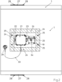
- Fig. 2 shows an outside of the shut-off device.
- a drive device 34 is provided, which is attached to the Outside of the housing 2.
- the drive device 34 interacts with the pivot axis 3.
- a position indicator 20 is provided.
- a module 21 is provided which is mounted by means of screws 22 on a bracket 23 fastened to the housing 2.
- a square enclosure 24 is provided which is fastened to the housing 2 by screws 25.
- the enclosure 24 consists of five calcium silicate plates and forms, together with the adjacent housing wall 1, a closed space in which the drive device 34 and the module 21 are arranged.
- a thermal trigger element 26 with a detection area 32 is provided on the outside of the housing 2. As in Fig.1 As shown, the detection area 32 extends through the housing wall 1 and projects into the housing 2. The trigger element 26 is connected to the drive device 34 and the module 21 via a cable 33.
- an inspection cover 27 is provided in each of two opposite housing wall sections of the housing 2, which is attached to the respective housing wall section by means of screws 28.
- Fig.3 is the detail "Z" from Fig.1 shown. How Fig.3 As can be seen, the flap leaf 5 has a continuous recess through which the pivot axis 3 is guided.
- the screw 16 is provided for the rotationally fixed fixation of the flap leaf 5 relative to the pivot axis 3.
- a milling 35 is provided in both surfaces of the flap leaf 5 on either side of the continuous recess through which the pivot axis 3 is guided.
- One milling 35 is deep enough to accommodate a plate 36 and the head of the screw 16, while the opposite milling 35 accommodates a plate 29.
- An internal thread is provided in the plate 29 into which the screw 16 is screwed.
- the plates 36, 29 are made of metal and serve to distribute forces.
- Each milling 35 is covered with a cover 30, each cover 30 being attached to the flap leaf 5 by means of screws 31.
- Each cover 30 serves as thermal protection for the fastening underneath in the form of the screw 16.
- the covers 30 can consist of calcium silicate plates, for example. How Fig.3 , the coating 17 also extends over the covers 30 so that the damper blade 5 is completely coated.
Landscapes
- Engineering & Computer Science (AREA)
- Chemical & Material Sciences (AREA)
- Combustion & Propulsion (AREA)
- Mechanical Engineering (AREA)
- General Engineering & Computer Science (AREA)
- Health & Medical Sciences (AREA)
- Public Health (AREA)
- Business, Economics & Management (AREA)
- Emergency Management (AREA)
- Air-Flow Control Members (AREA)
Claims (17)
- Dispositif d'isolement dévolu à l'utilisation dans une conduite d'air d'une installation technique de ventilation ou d'une installation de désenfumage automatique, ledit dispositif d'isolement incluant un boîtier (2) préférentiellement doté d'une section transversale rectangulaire, pouvant être parcouru par un fluide gazeux et muni d'une paroi (1), et un volet basculant (5) monté à pivotement dans ledit boîtier (2), autour d'un axe de pivotement (3), caractérisé par le fait que, pour une utilisation du dispositif d'isolement en association avec un fluide gazeux chimiquement agressif, au moins la totalité des régions dudit dispositif d'isolement, en contact avec le fluide circulant dans le boîtier (2), est conçue pour résister à des entrées en réaction chimique dommageables avec ce fluide, ou causées par ce fluide, l'aptitude à résister étant matérialisée par un revêtement (17) déposé sur lesdites régions entrant en contact avec ledit fluide en circulation.
- Dispositif d'isolement selon la revendication précédente, caractérisé par le fait qu'un revêtement en résine époxy à deux ou plusieurs composants est prévu en tant que revêtement (17).
- Dispositif d'isolement selon la revendication précédente, caractérisé par le fait que le revêtement (17) est exempt de solvant à l'état intégralement durci.
- Dispositif d'isolement selon l'une des deux revendications précédentes, caractérisé par le fait que le revêtement (17) est renforcé par de la céramique.
- Dispositif d'isolement selon l'une des revendications précédentes, caractérisé par le fait que le revêtement (17) est pulvérisable.
- Dispositif d'isolement selon l'une des revendications 1 à 4, caractérisé par le fait que le revêtement (17) peut être déposé mécaniquement.
- Dispositif d'isolement selon l'une des revendications précédentes, caractérisé par le fait qu'un apprêt est prévu entre le revêtement (17) et la région considérée.
- Dispositif d'isolement selon l'une des revendications précédentes, caractérisé par le fait qu'au moins une région partielle de la paroi (1) du boîtier, de préférence l'intégralité de ladite paroi (1) du boîtier, est constituée d'au moins un panneau de construction coupe-feu ou d'au moins un panneau de silicate de calcium lié au ciment.
- Dispositif d'isolement selon l'une des revendications précédentes, caractérisé par le fait que le volet basculant (5) est constitué d'au moins un panneau de construction coupe-feu, ou d'un panneau de silicate de calcium lié au ciment.
- Dispositif d'isolement selon l'une des revendications précédentes, caractérisé par le fait que ledit dispositif d'isolement est réalisé sous la forme d'un clapet de désenfumage.
- Dispositif d'isolement selon l'une des revendications précédentes, caractérisé par le fait que ledit dispositif d'isolement est réalisé sous la forme d'un clapet coupe-feu.
- Dispositif d'isolement selon la revendication précédente, caractérisé par le fait que le volet basculant (5) peut être verrouillé dans sa position ouverte au moyen d'un système de blocage à demeure, en opposition à une force de rappel, et peut pivoter vers sa position fermée à partir de la position verrouillée, sous l'effet de ladite force de rappel après relâchement dudit système de blocage à demeure, par exemple en cas d'incendie.
- Dispositif d'isolement selon l'une des revendications précédentes, caractérisé par le fait qu'un système d'entraînement (34) vient en prise indirecte ou directe avec le volet basculant (5).
- Dispositif d'isolement selon l'une des revendications précédentes, caractérisé par le fait qu'au moins une vis (16), traversant de préférence l'axe de pivotement (3), est prévue pour la fixation du volet basculant (5), avec verrouillage rotatif, par rapport audit axe de pivotement (3).
- Dispositif d'isolement selon la revendication précédente, caractérisé par le fait qu'un logement, de préférence un logement conçu en tant que fraisage (35), est prévu dans au moins une surface du volet basculant (5), afin de recevoir l'extrémité de la vis (16) située dans la région de cette surface dudit volet basculant (5).
- Dispositif d'isolement selon la revendication précédente, caractérisé par le fait qu'au moins un logement est obturé par un couvercle (30) fixé au volet basculant (5), de préférence au moyen de vis (31).
- Dispositif d'isolement selon l'une des revendications précédentes, caractérisé par le fait que ledit dispositif d'isolement inclut un accumulateur d'énergie.
Priority Applications (3)
| Application Number | Priority Date | Filing Date | Title |
|---|---|---|---|
| PL20165682.4T PL3885666T3 (pl) | 2020-03-25 | 2020-03-25 | Urządzenie odcinające do zastosowania w przewodzie powietrznym instalacji wentylacyjnej lub mechanicznej instalacji oddymiającej |
| EP20165682.4A EP3885666B9 (fr) | 2020-03-25 | 2020-03-25 | Dispositif d'arrêt destiné à être utilisé dans une conduite d'air d'une installation technique de ventilation ou d'une installation de désenfumage mécanique |
| ES20165682T ES2984031T3 (es) | 2020-03-25 | 2020-03-25 | Dispositivo de cierre para su uso en un conducto de aire de un sistema de ventilación o en una instalación mecánica de extracción de humos |
Applications Claiming Priority (1)
| Application Number | Priority Date | Filing Date | Title |
|---|---|---|---|
| EP20165682.4A EP3885666B9 (fr) | 2020-03-25 | 2020-03-25 | Dispositif d'arrêt destiné à être utilisé dans une conduite d'air d'une installation technique de ventilation ou d'une installation de désenfumage mécanique |
Publications (3)
| Publication Number | Publication Date |
|---|---|
| EP3885666A1 EP3885666A1 (fr) | 2021-09-29 |
| EP3885666B1 true EP3885666B1 (fr) | 2024-05-01 |
| EP3885666B9 EP3885666B9 (fr) | 2024-07-10 |
Family
ID=70008391
Family Applications (1)
| Application Number | Title | Priority Date | Filing Date |
|---|---|---|---|
| EP20165682.4A Active EP3885666B9 (fr) | 2020-03-25 | 2020-03-25 | Dispositif d'arrêt destiné à être utilisé dans une conduite d'air d'une installation technique de ventilation ou d'une installation de désenfumage mécanique |
Country Status (3)
| Country | Link |
|---|---|
| EP (1) | EP3885666B9 (fr) |
| ES (1) | ES2984031T3 (fr) |
| PL (1) | PL3885666T3 (fr) |
Family Cites Families (4)
| Publication number | Priority date | Publication date | Assignee | Title |
|---|---|---|---|---|
| DE1914738C3 (de) * | 1969-03-22 | 1973-09-27 | Deutsche Steinzeug- Und Kunststoffwarenfabrik, 6800 Mannheim | Brandschutz Verschlußeinrichtung |
| BE789110A (nl) * | 1971-09-25 | 1973-01-15 | Trox Gmbh Geb | Tbehandelingsinstallaties versperring voor brandzones in ventilatie- en luch |
| FR2648891B1 (fr) * | 1989-06-23 | 1991-10-18 | Sari | Clapet, notamment a usage de clapet coupe-feu ou de clapet de desenfumage |
| DE202015102532U1 (de) * | 2015-05-18 | 2015-07-16 | Trox Gmbh | Absperrklappe für den Einsatz in einem Kanal einer raumlufttechnischen Anlage oder einer maschinellen Entrauchungsanlage |
-
2020
- 2020-03-25 EP EP20165682.4A patent/EP3885666B9/fr active Active
- 2020-03-25 ES ES20165682T patent/ES2984031T3/es active Active
- 2020-03-25 PL PL20165682.4T patent/PL3885666T3/pl unknown
Also Published As
| Publication number | Publication date |
|---|---|
| ES2984031T3 (es) | 2024-10-28 |
| EP3885666B9 (fr) | 2024-07-10 |
| EP3885666A1 (fr) | 2021-09-29 |
| PL3885666T3 (pl) | 2024-09-02 |
Similar Documents
| Publication | Publication Date | Title |
|---|---|---|
| DE19720842C2 (de) | Hochtemperaturschutz-Einrichtung für ein elektronisches Gerät | |
| EP3907838B1 (fr) | Boitier de distributeur et/ou de protection contre les incendies, dispositif de protection contre les incendies et ensemble pour un boitier de distributeur et/ou de protection contre les incendies | |
| DE19524766C2 (de) | Brandschutz-Sperrvorrichtung für Lüftungsleitungen | |
| DE202004019510U1 (de) | Brandschutzschrank | |
| EP3885666B1 (fr) | Dispositif d'arrêt destiné à être utilisé dans une conduite d'air d'une installation technique de ventilation ou d'une installation de désenfumage mécanique | |
| EP2179768B1 (fr) | Dispositif anti-feu / de désenfumage | |
| EP2030651B1 (fr) | Dispositif de protection pour canaux d'aération | |
| EP0396785A1 (fr) | Dispositif d'obturation d'installations de ventilation | |
| EP2433676B1 (fr) | Boîtier ignifuge pour un convertisseur de courant | |
| DE10151584A1 (de) | Druckentlastungsklappe | |
| EP3144571A1 (fr) | Disque de rupture a isolation thermique | |
| EP1762276B1 (fr) | Mécanisme de déclenchement pour un elément obturateur fermant au moins un conduit d'une installation d'aérage | |
| DE9300568U1 (de) | Brandschutzabsperrung für brennbare Rohrleitungen | |
| DE2262541A1 (de) | Absperrvorrichtung gegen feuer und rauch | |
| EP3101363B1 (fr) | Clapet de fermeture destiné à être utilisé dans un canal d'une installation de ventilation ou d'une installation de désenfumage mécanique | |
| DE1914738C3 (de) | Brandschutz Verschlußeinrichtung | |
| EP0417874B1 (fr) | Système de ventilateur | |
| EP0454879B1 (fr) | Appareil de ventilation pour installation de ventilation individuelle | |
| DE2335393A1 (de) | Feuerschutzanordnung fuer lufttechnische anlagen | |
| DE19652780A1 (de) | Wartungsfreie Vorrichtung zur rauch- und brandsicheren Abschottung einer Lüftungsrohrleitung | |
| DE19700601A1 (de) | Verschlußeinrichtung für Strömungswege | |
| DE202020102591U1 (de) | Verteiler- und/oder Brandschutzgehäuse, Brandschutzeinrichtung und Bausatz für ein Verteiler- und/oder Brandschutzgehäuse | |
| EP0046481A1 (fr) | Volet coupe-feu | |
| EP2772283A2 (fr) | Clapet anti-feu destiné à empêcher la transmission de feu et de fumée dans un boîtier tubulaire | |
| DE19649126C2 (de) | Absperrvorrichtung gegen eine Brandübertragung |
Legal Events
| Date | Code | Title | Description |
|---|---|---|---|
| PUAI | Public reference made under article 153(3) epc to a published international application that has entered the european phase |
Free format text: ORIGINAL CODE: 0009012 |
|
| STAA | Information on the status of an ep patent application or granted ep patent |
Free format text: STATUS: THE APPLICATION HAS BEEN PUBLISHED |
|
| AK | Designated contracting states |
Kind code of ref document: A1 Designated state(s): AL AT BE BG CH CY CZ DE DK EE ES FI FR GB GR HR HU IE IS IT LI LT LU LV MC MK MT NL NO PL PT RO RS SE SI SK SM TR |
|
| STAA | Information on the status of an ep patent application or granted ep patent |
Free format text: STATUS: REQUEST FOR EXAMINATION WAS MADE |
|
| 17P | Request for examination filed |
Effective date: 20220321 |
|
| RBV | Designated contracting states (corrected) |
Designated state(s): AL AT BE BG CH CY CZ DE DK EE ES FI FR GB GR HR HU IE IS IT LI LT LU LV MC MK MT NL NO PL PT RO RS SE SI SK SM TR |
|
| P01 | Opt-out of the competence of the unified patent court (upc) registered |
Effective date: 20230512 |
|
| GRAP | Despatch of communication of intention to grant a patent |
Free format text: ORIGINAL CODE: EPIDOSNIGR1 |
|
| STAA | Information on the status of an ep patent application or granted ep patent |
Free format text: STATUS: GRANT OF PATENT IS INTENDED |
|
| RIC1 | Information provided on ipc code assigned before grant |
Ipc: F24F 11/35 20180101ALI20230612BHEP Ipc: A62C 2/12 20060101ALI20230612BHEP Ipc: F24F 13/14 20060101AFI20230612BHEP |
|
| INTG | Intention to grant announced |
Effective date: 20230706 |
|
| GRAJ | Information related to disapproval of communication of intention to grant by the applicant or resumption of examination proceedings by the epo deleted |
Free format text: ORIGINAL CODE: EPIDOSDIGR1 |
|
| STAA | Information on the status of an ep patent application or granted ep patent |
Free format text: STATUS: REQUEST FOR EXAMINATION WAS MADE |
|
| GRAS | Grant fee paid |
Free format text: ORIGINAL CODE: EPIDOSNIGR3 |
|
| STAA | Information on the status of an ep patent application or granted ep patent |
Free format text: STATUS: GRANT OF PATENT IS INTENDED |
|
| GRAP | Despatch of communication of intention to grant a patent |
Free format text: ORIGINAL CODE: EPIDOSNIGR1 |
|
| INTC | Intention to grant announced (deleted) | ||
| INTG | Intention to grant announced |
Effective date: 20231128 |
|
| GRAA | (expected) grant |
Free format text: ORIGINAL CODE: 0009210 |
|
| STAA | Information on the status of an ep patent application or granted ep patent |
Free format text: STATUS: THE PATENT HAS BEEN GRANTED |
|
| AK | Designated contracting states |
Kind code of ref document: B1 Designated state(s): AL AT BE BG CH CY CZ DE DK EE ES FI FR GB GR HR HU IE IS IT LI LT LU LV MC MK MT NL NO PL PT RO RS SE SI SK SM TR |
|
| REG | Reference to a national code |
Ref country code: GB Ref legal event code: FG4D Free format text: NOT ENGLISH |
|
| REG | Reference to a national code |
Ref country code: CH Ref legal event code: EP |
|
| REG | Reference to a national code |
Ref country code: IE Ref legal event code: FG4D Free format text: LANGUAGE OF EP DOCUMENT: GERMAN |
|
| REG | Reference to a national code |
Ref country code: DE Ref legal event code: R096 Ref document number: 502020007806 Country of ref document: DE |
|
| REG | Reference to a national code |
Ref country code: CH Ref legal event code: PK Free format text: BERICHTIGUNG B9 |
|
| REG | Reference to a national code |
Ref country code: NL Ref legal event code: FP |
|
| REG | Reference to a national code |
Ref country code: LT Ref legal event code: MG9D |
|
| PG25 | Lapsed in a contracting state [announced via postgrant information from national office to epo] |
Ref country code: IS Free format text: LAPSE BECAUSE OF FAILURE TO SUBMIT A TRANSLATION OF THE DESCRIPTION OR TO PAY THE FEE WITHIN THE PRESCRIBED TIME-LIMIT Effective date: 20240901 |
|
| PG25 | Lapsed in a contracting state [announced via postgrant information from national office to epo] |
Ref country code: BG Free format text: LAPSE BECAUSE OF FAILURE TO SUBMIT A TRANSLATION OF THE DESCRIPTION OR TO PAY THE FEE WITHIN THE PRESCRIBED TIME-LIMIT Effective date: 20240501 |
|
| PG25 | Lapsed in a contracting state [announced via postgrant information from national office to epo] |
Ref country code: HR Free format text: LAPSE BECAUSE OF FAILURE TO SUBMIT A TRANSLATION OF THE DESCRIPTION OR TO PAY THE FEE WITHIN THE PRESCRIBED TIME-LIMIT Effective date: 20240501 Ref country code: FI Free format text: LAPSE BECAUSE OF FAILURE TO SUBMIT A TRANSLATION OF THE DESCRIPTION OR TO PAY THE FEE WITHIN THE PRESCRIBED TIME-LIMIT Effective date: 20240501 |
|
| PG25 | Lapsed in a contracting state [announced via postgrant information from national office to epo] |
Ref country code: GR Free format text: LAPSE BECAUSE OF FAILURE TO SUBMIT A TRANSLATION OF THE DESCRIPTION OR TO PAY THE FEE WITHIN THE PRESCRIBED TIME-LIMIT Effective date: 20240802 |
|
| PG25 | Lapsed in a contracting state [announced via postgrant information from national office to epo] |
Ref country code: PT Free format text: LAPSE BECAUSE OF FAILURE TO SUBMIT A TRANSLATION OF THE DESCRIPTION OR TO PAY THE FEE WITHIN THE PRESCRIBED TIME-LIMIT Effective date: 20240902 |
|
| REG | Reference to a national code |
Ref country code: ES Ref legal event code: FG2A Ref document number: 2984031 Country of ref document: ES Kind code of ref document: T3 Effective date: 20241028 |
|
| PG25 | Lapsed in a contracting state [announced via postgrant information from national office to epo] |
Ref country code: LV Free format text: LAPSE BECAUSE OF FAILURE TO SUBMIT A TRANSLATION OF THE DESCRIPTION OR TO PAY THE FEE WITHIN THE PRESCRIBED TIME-LIMIT Effective date: 20240501 |
|
| PG25 | Lapsed in a contracting state [announced via postgrant information from national office to epo] |
Ref country code: PT Free format text: LAPSE BECAUSE OF FAILURE TO SUBMIT A TRANSLATION OF THE DESCRIPTION OR TO PAY THE FEE WITHIN THE PRESCRIBED TIME-LIMIT Effective date: 20240902 Ref country code: LV Free format text: LAPSE BECAUSE OF FAILURE TO SUBMIT A TRANSLATION OF THE DESCRIPTION OR TO PAY THE FEE WITHIN THE PRESCRIBED TIME-LIMIT Effective date: 20240501 Ref country code: IS Free format text: LAPSE BECAUSE OF FAILURE TO SUBMIT A TRANSLATION OF THE DESCRIPTION OR TO PAY THE FEE WITHIN THE PRESCRIBED TIME-LIMIT Effective date: 20240901 Ref country code: HR Free format text: LAPSE BECAUSE OF FAILURE TO SUBMIT A TRANSLATION OF THE DESCRIPTION OR TO PAY THE FEE WITHIN THE PRESCRIBED TIME-LIMIT Effective date: 20240501 Ref country code: GR Free format text: LAPSE BECAUSE OF FAILURE TO SUBMIT A TRANSLATION OF THE DESCRIPTION OR TO PAY THE FEE WITHIN THE PRESCRIBED TIME-LIMIT Effective date: 20240802 Ref country code: FI Free format text: LAPSE BECAUSE OF FAILURE TO SUBMIT A TRANSLATION OF THE DESCRIPTION OR TO PAY THE FEE WITHIN THE PRESCRIBED TIME-LIMIT Effective date: 20240501 Ref country code: BG Free format text: LAPSE BECAUSE OF FAILURE TO SUBMIT A TRANSLATION OF THE DESCRIPTION OR TO PAY THE FEE WITHIN THE PRESCRIBED TIME-LIMIT Effective date: 20240501 Ref country code: RS Free format text: LAPSE BECAUSE OF FAILURE TO SUBMIT A TRANSLATION OF THE DESCRIPTION OR TO PAY THE FEE WITHIN THE PRESCRIBED TIME-LIMIT Effective date: 20240801 |
|
| PG25 | Lapsed in a contracting state [announced via postgrant information from national office to epo] |
Ref country code: DK Free format text: LAPSE BECAUSE OF FAILURE TO SUBMIT A TRANSLATION OF THE DESCRIPTION OR TO PAY THE FEE WITHIN THE PRESCRIBED TIME-LIMIT Effective date: 20240501 |
|
| PG25 | Lapsed in a contracting state [announced via postgrant information from national office to epo] |
Ref country code: EE Free format text: LAPSE BECAUSE OF FAILURE TO SUBMIT A TRANSLATION OF THE DESCRIPTION OR TO PAY THE FEE WITHIN THE PRESCRIBED TIME-LIMIT Effective date: 20240501 |
|
| PG25 | Lapsed in a contracting state [announced via postgrant information from national office to epo] |
Ref country code: CZ Free format text: LAPSE BECAUSE OF FAILURE TO SUBMIT A TRANSLATION OF THE DESCRIPTION OR TO PAY THE FEE WITHIN THE PRESCRIBED TIME-LIMIT Effective date: 20240501 |
|
| PG25 | Lapsed in a contracting state [announced via postgrant information from national office to epo] |
Ref country code: SK Free format text: LAPSE BECAUSE OF FAILURE TO SUBMIT A TRANSLATION OF THE DESCRIPTION OR TO PAY THE FEE WITHIN THE PRESCRIBED TIME-LIMIT Effective date: 20240501 Ref country code: RO Free format text: LAPSE BECAUSE OF FAILURE TO SUBMIT A TRANSLATION OF THE DESCRIPTION OR TO PAY THE FEE WITHIN THE PRESCRIBED TIME-LIMIT Effective date: 20240501 |
|
| PG25 | Lapsed in a contracting state [announced via postgrant information from national office to epo] |
Ref country code: SM Free format text: LAPSE BECAUSE OF FAILURE TO SUBMIT A TRANSLATION OF THE DESCRIPTION OR TO PAY THE FEE WITHIN THE PRESCRIBED TIME-LIMIT Effective date: 20240501 |
|
| PG25 | Lapsed in a contracting state [announced via postgrant information from national office to epo] |
Ref country code: SM Free format text: LAPSE BECAUSE OF FAILURE TO SUBMIT A TRANSLATION OF THE DESCRIPTION OR TO PAY THE FEE WITHIN THE PRESCRIBED TIME-LIMIT Effective date: 20240501 Ref country code: SK Free format text: LAPSE BECAUSE OF FAILURE TO SUBMIT A TRANSLATION OF THE DESCRIPTION OR TO PAY THE FEE WITHIN THE PRESCRIBED TIME-LIMIT Effective date: 20240501 Ref country code: RO Free format text: LAPSE BECAUSE OF FAILURE TO SUBMIT A TRANSLATION OF THE DESCRIPTION OR TO PAY THE FEE WITHIN THE PRESCRIBED TIME-LIMIT Effective date: 20240501 Ref country code: EE Free format text: LAPSE BECAUSE OF FAILURE TO SUBMIT A TRANSLATION OF THE DESCRIPTION OR TO PAY THE FEE WITHIN THE PRESCRIBED TIME-LIMIT Effective date: 20240501 Ref country code: DK Free format text: LAPSE BECAUSE OF FAILURE TO SUBMIT A TRANSLATION OF THE DESCRIPTION OR TO PAY THE FEE WITHIN THE PRESCRIBED TIME-LIMIT Effective date: 20240501 Ref country code: CZ Free format text: LAPSE BECAUSE OF FAILURE TO SUBMIT A TRANSLATION OF THE DESCRIPTION OR TO PAY THE FEE WITHIN THE PRESCRIBED TIME-LIMIT Effective date: 20240501 |
|
| REG | Reference to a national code |
Ref country code: DE Ref legal event code: R097 Ref document number: 502020007806 Country of ref document: DE |
|
| PG25 | Lapsed in a contracting state [announced via postgrant information from national office to epo] |
Ref country code: IT Free format text: LAPSE BECAUSE OF FAILURE TO SUBMIT A TRANSLATION OF THE DESCRIPTION OR TO PAY THE FEE WITHIN THE PRESCRIBED TIME-LIMIT Effective date: 20240501 |
|
| PLBE | No opposition filed within time limit |
Free format text: ORIGINAL CODE: 0009261 |
|
| STAA | Information on the status of an ep patent application or granted ep patent |
Free format text: STATUS: NO OPPOSITION FILED WITHIN TIME LIMIT |
|
| 26N | No opposition filed |
Effective date: 20250204 |
|
| REG | Reference to a national code |
Ref country code: DE Ref legal event code: R081 Ref document number: 502020007806 Country of ref document: DE Owner name: TROX SE, DE Free format text: FORMER OWNER: TROX GMBH, 47506 NEUKIRCHEN-VLUYN, DE |
|
| PG25 | Lapsed in a contracting state [announced via postgrant information from national office to epo] |
Ref country code: SI Free format text: LAPSE BECAUSE OF FAILURE TO SUBMIT A TRANSLATION OF THE DESCRIPTION OR TO PAY THE FEE WITHIN THE PRESCRIBED TIME-LIMIT Effective date: 20240501 |
|
| PGFP | Annual fee paid to national office [announced via postgrant information from national office to epo] |
Ref country code: PL Payment date: 20250214 Year of fee payment: 6 |
|
| PGFP | Annual fee paid to national office [announced via postgrant information from national office to epo] |
Ref country code: ES Payment date: 20250416 Year of fee payment: 6 |
|
| PGFP | Annual fee paid to national office [announced via postgrant information from national office to epo] |
Ref country code: CH Payment date: 20250401 Year of fee payment: 6 |
|
| PG25 | Lapsed in a contracting state [announced via postgrant information from national office to epo] |
Ref country code: SE Free format text: LAPSE BECAUSE OF FAILURE TO SUBMIT A TRANSLATION OF THE DESCRIPTION OR TO PAY THE FEE WITHIN THE PRESCRIBED TIME-LIMIT Effective date: 20240501 |
|
| PG25 | Lapsed in a contracting state [announced via postgrant information from national office to epo] |
Ref country code: MC Free format text: LAPSE BECAUSE OF FAILURE TO SUBMIT A TRANSLATION OF THE DESCRIPTION OR TO PAY THE FEE WITHIN THE PRESCRIBED TIME-LIMIT Effective date: 20240501 |
|
| PG25 | Lapsed in a contracting state [announced via postgrant information from national office to epo] |
Ref country code: LU Free format text: LAPSE BECAUSE OF NON-PAYMENT OF DUE FEES Effective date: 20250325 |
|
| PG25 | Lapsed in a contracting state [announced via postgrant information from national office to epo] |
Ref country code: IE Free format text: LAPSE BECAUSE OF NON-PAYMENT OF DUE FEES Effective date: 20250325 |
|
| REG | Reference to a national code |
Ref country code: CH Ref legal event code: U11 Free format text: ST27 STATUS EVENT CODE: U-0-0-U10-U11 (AS PROVIDED BY THE NATIONAL OFFICE) Effective date: 20260401 |
|
| PGFP | Annual fee paid to national office [announced via postgrant information from national office to epo] |
Ref country code: GB Payment date: 20260317 Year of fee payment: 7 |
|
| PGFP | Annual fee paid to national office [announced via postgrant information from national office to epo] |
Ref country code: NO Payment date: 20260320 Year of fee payment: 7 Ref country code: DE Payment date: 20260305 Year of fee payment: 7 |
|
| PGFP | Annual fee paid to national office [announced via postgrant information from national office to epo] |
Ref country code: AT Payment date: 20260319 Year of fee payment: 7 |
|
| PGFP | Annual fee paid to national office [announced via postgrant information from national office to epo] |
Ref country code: BE Payment date: 20260323 Year of fee payment: 7 |
|
| PGFP | Annual fee paid to national office [announced via postgrant information from national office to epo] |
Ref country code: NL Payment date: 20260323 Year of fee payment: 7 |
|
| PGFP | Annual fee paid to national office [announced via postgrant information from national office to epo] |
Ref country code: FR Payment date: 20260325 Year of fee payment: 7 |