EP3887164B1 - Unité de séchage pour sécher des substrats imprimés - Google Patents
Unité de séchage pour sécher des substrats imprimés Download PDFInfo
- Publication number
- EP3887164B1 EP3887164B1 EP19795139.5A EP19795139A EP3887164B1 EP 3887164 B1 EP3887164 B1 EP 3887164B1 EP 19795139 A EP19795139 A EP 19795139A EP 3887164 B1 EP3887164 B1 EP 3887164B1
- Authority
- EP
- European Patent Office
- Prior art keywords
- chamber
- cylinder
- printing
- drying unit
- substrates
- Prior art date
- Legal status (The legal status is an assumption and is not a legal conclusion. Google has not performed a legal analysis and makes no representation as to the accuracy of the status listed.)
- Active
Links
Images


Classifications
-
- B—PERFORMING OPERATIONS; TRANSPORTING
- B41—PRINTING; LINING MACHINES; TYPEWRITERS; STAMPS
- B41F—PRINTING MACHINES OR PRESSES
- B41F23/00—Devices for treating the surfaces of sheets, webs, or other articles in connection with printing
- B41F23/04—Devices for treating the surfaces of sheets, webs, or other articles in connection with printing by heat drying, by cooling, by applying powders
- B41F23/044—Drying sheets, e.g. between two printing stations
- B41F23/045—Drying sheets, e.g. between two printing stations by radiation
- B41F23/0453—Drying sheets, e.g. between two printing stations by radiation by ultraviolet dryers
-
- B—PERFORMING OPERATIONS; TRANSPORTING
- B41—PRINTING; LINING MACHINES; TYPEWRITERS; STAMPS
- B41F—PRINTING MACHINES OR PRESSES
- B41F23/00—Devices for treating the surfaces of sheets, webs, or other articles in connection with printing
- B41F23/04—Devices for treating the surfaces of sheets, webs, or other articles in connection with printing by heat drying, by cooling, by applying powders
- B41F23/044—Drying sheets, e.g. between two printing stations
- B41F23/045—Drying sheets, e.g. between two printing stations by radiation
-
- B—PERFORMING OPERATIONS; TRANSPORTING
- B41—PRINTING; LINING MACHINES; TYPEWRITERS; STAMPS
- B41F—PRINTING MACHINES OR PRESSES
- B41F23/00—Devices for treating the surfaces of sheets, webs, or other articles in connection with printing
- B41F23/04—Devices for treating the surfaces of sheets, webs, or other articles in connection with printing by heat drying, by cooling, by applying powders
- B41F23/0486—Particular types of dryers
-
- B—PERFORMING OPERATIONS; TRANSPORTING
- B41—PRINTING; LINING MACHINES; TYPEWRITERS; STAMPS
- B41F—PRINTING MACHINES OR PRESSES
- B41F9/00—Rotary intaglio printing presses
- B41F9/02—Rotary intaglio printing presses for multicolour printing
- B41F9/021—Sheet printing presses
Definitions
- the invention relates to a drying unit for drying printed substrates according to the preamble of claim 1.
- a drying system for radiation drying of paints and/or varnishes and/or coatings on substrates on printing and/or coating machines consisting of a radiator module and an inerting chamber, the inerting chamber consisting of a base body, a nozzle system, lateral sealing elements and an inlet - and an outlet element, the lateral sealing elements and the outlet element seal the inerting chamber from the sheet-guiding cylinder and the inlet element seals the inerting chamber from the cylinder gap between the sheet-guiding cylinder and the cylinder upstream of the drying system, viewed in the direction of paper travel, and a for the drying radiation on the base body of the inerting chamber permeable area is formed.
- UV emitters or so-called excimer UV emitters are used as emitters for the drying processes. Nitrogen is usually used as the inert gas. With the desired inerting, the remaining oxygen content should be reduced to a value below one percent.
- a sheet-fed printing press with a plurality of printing units is known, with the respective printing units being designed as printing units that print in a gravure printing process, and with at least one dryer comprising a radiator being assigned to the respective printing units.
- Drying and/or curing of lacquers and/or inks on sheets in sheet-fed printing presses is known, with the dryer being assigned to the sheet conveyed onto a sheet-guiding cylinder along the sheet conveying path, and at least one excimer emitter and at least one inert gas blower being surrounded by a bell, the bell from side parts assigned to both sides of the sheet-guiding cylinder and an upper region extending across the width of the sheet conveying path and having an inlet and outlet part, and the bell with the sheet-guiding cylinder and with at least one further cylinder encloses the interior space.
- DE 100 83 500 T1 discloses a method and apparatus for irradiating an object with an active energy ray when an inert gas or reactive gas atmosphere is required for irradiation in an irradiation chamber with an active energy ray.
- a printing formeless printing unit is known in a hybrid sheetfed offset printing press for printing individualizing the printed sheets to be processed, with at least one inkjet printhead being integrated in a printing unit, in a varnishing unit, in a feed area and/or in a delivery area of the hybrid sheetfed offset printing press, wherein in the hybrid sheet-fed offset printing machine, printed sheets are printed with a static single-color or multi-color print image using the offset printing process and with a variable, individualizing print image using the inkjet printing process, with a modular printing unit being provided which has at least one inkjet print head and whose structure is variable, with the modular printing unit is formed in its functional structure from other modular units and wherein the Module units are selected and arranged in a configurable and positionable manner in the hybrid sheetfed offset printing press, depending on a given printing task and one or more selectable framework conditions, at least on the basis of a parameter set from the specified print subject, quantity to be printed, quality requirements for the print, substrate material, coating material,
- a device for curing a layer of printing ink, lacquer, adhesive or silicone, with which a substrate made of paper, plastic, glass, wood or metal is coated, with a housing which points in the direction of a transport body transporting the substrate is open and covers the substrate while maintaining substrate inlet and substrate outlet gaps, and with a UV lamp arranged inside the housing with a reflector which directs the UV light onto the substrate passing through, with at least one flushing gas line connected on the one hand to a flushing gas source and on the other hand to the interior of the housing via a nozzle, in addition to the substrate inlet gap and the substrate outlet gap, flushing gas nozzles which can preferably be cooled with water are provided, the flow direction angles of which can be adjusted in relation to the substrate passing through and which are in flow connection with a gas flow direction and quantity regulator stand, wherein a temperature control device is provided for cooling the substrate passing through, wherein the flushing gas nozzles are provided on the side walls of the housing and cooling channels
- An inerting device for emitter devices for drying and/or curing inks and/or varnishes within printing presses is known, in particular for sheet-fed printing presses with excimer emitters and blowing nozzles arranged inside the inertizing chamber, with the blowing nozzles being able to be throttled and/or switched off in certain areas over the width of the printing material web formed and the blast nozzles and/or excimer emitters are preceded by a control device that detects the front and rear edges of the printing material and controls the blast nozzles and/or excimer emitters.
- a device for treating sheet-shaped substrate with a sheet-guiding cylinder and an inerting device assigned to the sheet-guiding cylinder, wherein the sheet-guiding cylinder has first holding means for holding the front edge of the substrate and second holding means are provided, which hold the substrate on the sheet-guiding cylinder in a region spaced apart from the front edge of the substrate and wherein the substrate guided by the sheet guiding cylinder can be subjected to inert gas, wherein a third holding means is arranged outside the periphery of the sheet guiding cylinder.
- the invention is based on the object of creating a drying unit for drying printed substrates, the drying unit being suitable in an industrial production process for the highest possible printing speed in a printing machine.
- drying unit of the printing press is suitable in an industrial production process for the highest possible printing speed of the printing press. Further advantages can be seen from the exemplary embodiments described.
- the printing machine is z. B. designed as a sheet-fed printing press, preferably as a sheet-fed rotary printing press, in particular as a sheet-fed gravure printing machine, very particularly as a sheet-fed rotary printing press printing in an intaglio printing process.
- the intaglio printing process is a gravure printing process which is preferably used for the industrial production of banknotes, security documents or security elements.
- the ink applied to the printed sheets 21 and/or the varnish applied to the printed sheets 21 are preferably dried.
- Non-running, ie viscous printing inks and/or varnishes are preferably used.
- radiation-curing printing inks and/or lacquers are used.
- solvent-free printing inks and/or varnishes that can be cured by an electron beam are used. Such printing inks and/or lacquers polymerize within milliseconds when irradiated with an electron beam and are therefore dried in an extremely short time.
- An ink film or lacquer film consisting of such printing inks and/or lacquers is completely polymerized and is thus also hardened through, so that after drying in the printing inks or lacquers no fragments or cleavage residues remain that could migrate elsewhere through the substrate 21 .
- Printing inks or coatings dried by an electron beam form an elastic, glossy ink film or coating film, which is highly resistant to scratches and chemicals.
- the problem with a drying process using an electron beam is that the drying, i.e. the setting reaction, must take place in an oxygen-reduced, inert atmosphere in which the oxygen content is at most 1% to achieve high production quality, preferably in a range between 300 ppm and 500 ppm, in particular in the range between 150 ppm and 250 ppm, optionally even lower down to the range of less than 50 ppm, the oxygen content permissible in the inert atmosphere depending on the material of the substrate 21 used and/or the chemical composition of the printing ink used ( n) or paints. Otherwise, i.e.
- the free radicals contained in the still liquid printing inks or varnishes ie atoms or groups of atoms each containing a free electron
- the free radicals contained in the still liquid printing inks or varnishes would chemically react faster with the oxygen molecules contained in this air than with each other and only an incomplete one , form uneven cross-linking.
- the setting reaction results in the ink or varnish still being wet, tacky and lacking in gloss, with poor adhesion properties and poor scratch resistance.
- an inert i. H. a chemically very inert gas, e.g. B. an elementary gas such as nitrogen or a noble gas such as helium, neon, argon, krypton, xenon or radon or a gaseous molecular compound such as sulfur hexafluoride and carbon dioxide displaces the oxygen contained in the air.
- An inert gas prevents oxidative processes due to the displacement or significant reduction of oxygen.
- Atmosphere here and in the following - insofar as it relates to the volume of the drying unit 22 - refers holistically to that gaseous medium reduced in oxygen by the inert gas, which is present in the drying unit 22 in a space provided for drying the printing inks or the paint.
- a drying unit 22 that can be used in connection with a printing machine, in particular with the printing machine described above by way of example, has a drying unit 22 that is separated from the substrate 21, e.g. B. the printed sheet 21 traversed filled with an inert gas or at least one inert gas contained chamber 23, wherein at the entrance of the chamber 23 at which the printed sheets 21 are ushered into the chamber 23 containing the inert gas, z. B.
- a squeegee nozzle 24 is arranged, in particular in the form of a nozzle bar, in order to prevent the inert gas from escaping from the chamber 23 at this input and/or oxygen from the ambient air entering this chamber 23. Due to the flat nature of the printed sheets 21, the entrance to the chamber 23 is generally designed as a narrow slot extending transversely to the transport direction T of the printed sheets 21 over their entire width.
- an inert gas into the chamber 23 is provided, in particular a remotely controllable filling nozzle 26, this filling nozzle 26 being connected to an inert gas source, e.g. B. is connected to a tank.
- a sensor 27 for measuring the oxygen content in the chamber 23 containing the inert gas is preferably provided.
- the filling nozzle 26 is preferably controlled or at least controllable as a function of a measurement result from the sensor 27 for measuring the oxygen content in the chamber 23 containing the inert gas with regard to the admission of inert gas into the chamber 23 . Accordingly, if a filling nozzle 26 connected to the inert gas source, in particular a remotely actuatable filling nozzle, and a sensor 27 for measuring the oxygen content present in this chamber 23 are provided in each chamber 23 of the drying unit 22, then the proportion of oxygen in the inert atmosphere prevailing in this chamber 23 is advantageous e.g. B.
- control unit in particular automatically depending on a measurement result of the sensor 27 for measuring the oxygen content and/or depending on the material of the printed sheets 21 to be dried and/or depending on the chemical composition of at least one printing ink applied to the printed sheets 21 or one Lackes set or at least adjustable.
- the drying unit 22 has an electron beam generator 28 which is arranged in a vacuum chamber 29 .
- the vacuum chamber 29 and the chamber 23 filled with the inert gas are spatially separated from one another by a window.
- the window has a closure 31 z. B. from a titanium foil in a material thickness in the range of z. B. 0.01 mm and 0.3 mm, preferably at about 0.2 mm.
- the electron beam generator 28 has a cathode 32 z. B. in the form of a glow wire and an anode 33 spaced from the cathode 32 . Electrons emerging from the cathode 32 are accelerated in the direction of the anode 33 to almost the speed of light by an electrical voltage applied between the cathode 32 and the anode 33 .
- the electrical voltage for accelerating the electrons depends on a condition, e.g. B. chemical composition of the inks used and / or the desired depth of penetration into these inks and / or the material of the substrate 21 used in the range z. B. between 80 keV and 300 keV.
- these electrons impinge on the substrate 21 in a layer thickness of z. B.
- Oligomers used in inks suitable for an intaglio printing process include e.g. B. epoxy acrylates, acrylated oils, urethane acrylates, polyester acrylates, silicone acrylates, acrylated amines, acrylic saturated resins and acrylic acrylates.
- diluents are required to reduce the overall viscosity of an electron beam curing ink and thereby aid in the handling and application of these inks, e.g. B. to make these printing inks suitable for wiping on the plate cylinder 06 by the wiping cylinder 07.
- Suitable diluents can be water or include "reactive" monomers incorporated into the subject ink.
- Reactive monomers are typically acrylates or methacrylates and can be monofunctional or multifunctional. Examples of multifunctional monomers would be polyester acrylates or polyester methacrylates, polyol acrylates or polyomethacrylates, and polyether acrylates or polyether methacrylates.
- composition of layers of printing inks or varnishes each of which can be dried by an electron beam:
- Ebecryl TM 83 Cytec Surface Specialties polyether acrylate oligomer 60 TPGDA Rahn or Sartomer tripropylene glycol diacrylate 35 Darocur® 1173 Ciba Specialty Chemicals 2-Hydroxy-2-methyl-1-phenyl-propan-1-one 5
- Ebecryl TM 270 (Eb 270) Cytec Surface Specialties Urethane acrylate oligomer (aliphatic) 25 Ebecryl TM 265 (Eb 265) Cytec Surface Specialties Urethane acrylate oligomer (aliphatic, trifunctional) 30 Genome 1122 Rahn Urethane acrylate (monofunctional) 40 Darocur® 1173 Ciba Specialty 2-Hydroxy-2-methyl-1-phenyl- 5 chemicals propan-1-one
- Ebecryl TM 130 (Eb 130) Cytec Surface Specialties tricyclodecanedimethanol diacrylate 25.0 Sartomer 238 (HDDA) Sartomer 1,6-hexanediol diacrylate 10.0 Miramer 600 (DPHA) Rahn dipentaerythritol hexacrylate 5.0 Ebecryl TM 220 (Eb 220) Cytec Surface Specialties Urethane acrylate oligomer (aromatic, hexafunctional) 40.0 Ebecryl TM 83 (Eb 83) Cytec Surface Specialties Polyether acrylate oligomer (multifunctional) 11.8 Darocur® 1173 Ciba Specialty Chemicals 2-Hydroxy-2-methyl-1-phenyl-propan-1-one 8.0 Irgacure TM 369 (IR 369) Ciba Specialty Chemicals 2-Benzyl-2-dimethylamino-1-(4-morpholinophene TM 369 (IR 369) Ciba Special
- the drying unit 22 has an electron beam generator 28, by means of which high-energy electrons are fired onto the substrate 21.
- a first arrangement variant not according to the invention provides for arranging the entire printing machine in a housing that is sealed with respect to the ambient air, with an inert atmosphere having an oxygen content of at most 1% being provided inside the housing.
- the chamber 23 of the drying unit 22 containing the inert gas is realized here by the housing of the printing machine.
- the printed sheets 21 to be printed are fed to the printing press through an inlet lock formed on the housing and removed from the printing press through an outlet lock formed on the housing.
- the drying unit 22 is at any point in the transport direction T of the particular embodied as a printed sheet 21 Substrates 21 after that of impression cylinder 04 and plate cylinder 06 formed pressure gap 17, z. B.
- B. is designed as a circulating conveyor belt or as a circulating chain system or as a chain gripper system.
- a second arrangement variant provides for the drying unit 22 to be arranged in the printing unit 03 of the printing press.
- the chamber 23 of the drying unit 22 containing the inert gas is arranged in the printing unit 03 in such a way that at least one arcuate section of the printing cylinder 04 is arranged within this chamber 23.
- an arc section of the impression cylinder 04 and an arc section of the plate cylinder 06 interacting with this impression cylinder 04 are arranged within the chamber 23 containing the inert gas.
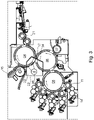
- FIG. 3 shows an excerpt from the in the 1 The printing press shown, wherein an arcuate section of the impression cylinder 04 and an arcuate section of the plate cylinder 06 interacting with this impression cylinder 04 are arranged within the chamber 23 containing the inert gas.
- a preferably flexible seal 34 is arranged on the chamber 23 containing the inert gas, which seals this chamber 23 on the respective end faces of the printing cylinder 04 and plate cylinder 06 and on the lateral surface of the plate cylinder 06 and, if necessary, on the printing gap 17 formed by the printing cylinder 04 and the plate cylinder 06 and seals against the ambient air at an exit from the chamber 23 on the dried substrate 21 resting on the lateral surface of the rotating printing cylinder 04.
- the impression cylinder 04 and the plate cylinder 06 are set against one another in the printing gap 17 they form under high pressure in a printing process carried out by the printing press in question, and the cylinders 04; 06 in the pressure gap 17 formed by them already an axial to these cylinders 04; 06 form running seal for the chamber 23 containing the inert gas.
- Substrates 21, in particular printed sheets 21, dried by means of drying unit 22 are transferred from printing cylinder 04 to a transport device 16 that follows printing cylinder 04 in transport direction T of printed sheets 21.
- FIG. 4 also shows an excerpt from the 1 illustrated printing machine, wherein only a sheet section of the printing cylinder 04 is arranged within the chamber 23 containing the inert gas.
- a preferably flexible seal 34 is arranged on the chamber 23 containing the inert gas, which seals this chamber 23 against the ambient air at the end faces of the pressure cylinder 04 and at an exit from the chamber 23 on the dry substrate 21 resting on its lateral surface.
- a narrow slot that extends transversely to transport direction T of substrate 21 over its entire width, through which slot a substrate 21 lying on the lateral surface of printing cylinder 04 is or at least can be inserted into chamber 23 of drying unit 22 , a squeegee nozzle 24, in particular in the form of a nozzle bar, being arranged along this slot in order to prevent the inert gas from escaping from the chamber 23 at this inlet and/or oxygen from the ambient air from entering this chamber 23.
- substrates 21, in particular printed sheets 21, that have been dried by the drying unit 22 are transferred from the printing cylinder 04 to a transport device 16 that follows the printing cylinder 04 in the transport direction T of the printed sheets 21.
- FIG 5 also shows an excerpt from the in the 1 Printing machine shown, in contrast to that in which 1 illustrated embodiment in the printing nip 17 between the printing cylinder 04 and the plate cylinder 06 printed sheets 21 via two in the transport direction T of the printed sheets 21 arranged one after the other intermediate cylinders 36; 37 are transferred to the transport device 16.
- the drying unit 22 is mounted on one of the intermediate cylinders 36; 37 is arranged.
- a preferably flexible seal 34 is in turn arranged on the chamber 23 containing the inert gas, which seals this chamber 23 on the end faces of the relevant intermediate cylinder 36; 37 and at an exit from the chamber 23 on the lateral surface of the concerned intermediate cylinder 36; 37 overlying dry substrate 21 seals each against the ambient air.
- a narrow slit extending transversely to the transport direction T of the substrate 21 over its entire width, through which slit an on the lateral surface of the relevant intermediate cylinder 36; 37 is inserted or at least can be inserted into the chamber 23 of the drying unit 22, with a squeegee nozzle 24 being arranged along this slot, in particular in the form of a nozzle bar, in order to prevent the inert gas from escaping from the chamber 23 at this entrance and /or oxygen from the ambient air enters this chamber 23.
- drying unit 22 on or at least in connection with the z. B. designed as a conveyor belt transport device 16 is arranged.
- a preferably flexible seal 34 is in turn arranged on the chamber 23 containing the inert gas, which seals this chamber 23 against the ambient air at the exit from the chamber 23 on the dry substrate 21 transported by the transport device 16 .
- a narrow slit that extends transversely to transport direction T of substrate 21 over its entire width, through which slit a substrate 21 transported by transport device 16 is introduced or at least can be introduced into chamber 23 of drying unit 22, wherein a squeegee nozzle 24, in particular in the form of a nozzle bar, is arranged along this slot in order to prevent the inert gas from escaping from the chamber 23 at this inlet and/or oxygen from the ambient air from entering this chamber 23.
- the drying unit 22, which has a chamber 23 containing the inert gas, can be located in the printing unit 03 of the printing press or, not according to the invention, on an intermediate cylinder 36; 37 or at the the substrates 21 to a delivery 18 transporting transport device 16 may be arranged.
- the 7 and 8th 12 show, by way of example, schematically various configurations of the drying unit 22 for electron beam curing that are not according to the invention.
- a drying unit 22 for electron beam curing which is placed on a suction cylinder 38, the suction cylinder 38 having a special configuration, e.g. B. the pressure cylinder 04 or an intermediate cylinder 36; 37 and has at least one arcuate section located within the chamber 23 of the drying unit 22.
- a first transport device e.g. B. in the form of a conveyor belt, in particular a suction belt 39 preferably having a suction box 41, or a cylinder or a roller leads printed substrates 21 to the suction cylinder 38 sequentially, wherein the suction cylinder 38 successively several, z.
- the B. can accommodate three substrates 21 designed in particular as printed sheets 21 .
- the substrates 21 supplied to the suction cylinder 38 are held on its lateral surface by suction air. With a continued rotation of the suction cylinder 38, the printed substrates 21 are guided through a narrow slot extending transversely to the transport direction T of the substrates 21 over their entire width into the chamber 23 of the drying unit 22 containing the inert gas.
- the electron beam generator 28 is located in the drying unit 22 and dries the printed substrates 21 by bombarding them with high-energy electrons in the manner described above.
- a second transport device e.g. B. again in the form of a conveyor belt, in particular one preferably having a suction box 43 Suction belt 42, or a cylinder or a roller arranged which the dried substrates 21 z. B. transported to a display 18.
- the first pneumatic system uses a pump 44 and usually via appropriate lines z. B. on the suction cylinder 38 and / or on the suction box 41 of the suction belt 39 of the first transport device and / or on the suction box 43 of the suction belt 42 of the second transport device, the suction air required to hold the substrates 21 to be transported is available.
- the second pneumatic system has an inert gas source z. B.
- the second pneumatic system has an input side z. B. with the suction cylinder 38 and on the outlet side with the tank 46 connected pump 47 in order to hold a substrate 21, which is arranged on the curved section of the suction cylinder 38 located within the chamber 23 of the drying unit 22, on the lateral surface of this suction cylinder 38 by suction .
- the second pneumatic system also generates suction air, with this suction air used in the second pneumatic system having an inert atmosphere with a significantly reduced oxygen content compared to the ambient air usually used by the first pneumatic system, with an oxygen content of preferably at most 1%.
- z. B only a single pneumatic system is provided, with the same gaseous medium as in the chamber 23 of the drying unit 22 being provided for the suction air required to hold the substrates 21 to be transported on the lateral surface of the suction cylinder 38, in particular during their entire dwell time on the relevant suction cylinder 38 . This results z. B.
- a rotary printing press with at least one printing unit 03 for printing on substrates 21, the printing unit 03 in question having at least two interacting cylinders 04; 06, wherein at least one of these cylinders 04; 06 is designed as a suction cylinder that transports the substrates 21 on its lateral surface, with a pneumatic system for providing the necessary suction air for holding the suction cylinder on the lateral surface of the relevant cylinder 04; 06 to be transported substrates 21 is provided.
- a drying unit 22 is provided in or after the printing unit 03 in question in the transport path of the substrates 21, with substrates 21 printed by the printing unit 03 in question being guided or at least being able to be guided through a chamber 23 of this drying unit 22, with the drying unit 22 entering the chamber 23 is provided by an inert gas oxygen-reduced gaseous medium.
- the suction air provided in the pneumatic system for holding the substrates 21 to be transported on the lateral surface of the relevant suction cylinder is the same gaseous medium as in the chamber 23 of the drying unit 22.
- One of the cylinders 04 working together in the relevant printing unit 03 is preferably a a printing cylinder 04 and the other cylinder 06 interacting with the printing cylinder 04 are embodied as a plate cylinder 06 applying a printed image to the substrates 21 in question.
- the printing unit 03 in question is one that prints using an intaglio printing process, in particular an intaglio printing process Printing unit 03 formed.
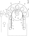
- FIG. 8 shows a non-inventive embodiment of the drying unit 22 for electron beam curing, in which for the transport of the substrates 21 through the chamber 23 of the drying unit 22 in a vacuum chamber 29 having the electron beam generator 28 partially, e.g. B. housing 49 enclosing it in a semicircle, several suction rollers 48 are provided along the transport path of the substrates 21, with these suction rollers 48 conveying substrates 21 introduced into the chamber 23 of the drying unit 22 by their respective rotation from an inlet of the chamber 23 to its outlet.
- the electron beam generator 28 is z. B.
- the drying unit 22 in or near the center of the drying unit 22 and has a radially outwardly directed electron beam, wherein substrates to be dried 21 each facing the electron beam generator 28 with their printed side along their transport path at least partially, z. B. in a semicircle in an arc around the vacuum chamber 29 having the electron beam generator 28 or are guided.
- the suction rollers 48 arranged along the transport path of the substrates 21 are each arranged on the side of these substrates 21 to be conveyed through the chamber 23 of the drying unit 22 that is not to be dried.
- the entrance of the chamber 23 and its exit are preferably each formed as a narrow slot extending transversely to the transport direction T of the substrates 21 over their entire width.
- a first transport device arranged in the transport direction T of the substrates 21 immediately before the entrance of the chamber 23 is z. B. in the form of a conveyor belt, in particular a suction belt 39 preferably having a suction box 41, or a cylinder or a roller and guides printed substrates 21 to the chamber 23 of the drying unit 22 sequentially.
- a second transport device e.g. B. in turn in the form of a conveyor belt, in particular a suction belt 42 preferably having a suction box 43, or a cylinder or a roller, which transports the dried substrates 21 z. B. transported to a display 18.
- the first pneumatic system uses a pump 44 and appropriate lines z. B. at the suction box 41 of the suction belt 39 of the first transport device and / or at the suction box 43 of the suction belt 42 of the second transport device, the respectively required suction air for holding the substrates 21 to be transported are available.
- the second pneumatic system has an inert gas source z. B. in the form of a tank 46 for providing the inert gas required by the drying unit 22, the filling nozzle 26 which is arranged on the chamber 23 of the drying unit 22 and admits inert gas into the chamber 23 being connected to this tank 46. Furthermore, the second pneumatic system z. B.
- a pump 47 connected on the input side to the suction rollers 48 and on the output side to the tank 46, wherein a substrate 21, which is conveyed through the suction rollers 48 on the transport path located within the chamber 23 of the drying unit 22, is caused by a pump 47 Suction is kept on the intended transport path.
- the input provided for the substrates 21 in the chamber 23 of the drying unit 22 and / or the output from this chamber 23 are z. B. slit-shaped and / or each z. B. sealed by a squeegee nozzle 24 in particular in the form of a nozzle bar or by a preferably flexible seal 34.
- a further measure for minimizing the escape of the oxygen-reduced gaseous medium, in particular inert gas, from the chamber 23 and/or an undesired entry of oxygen from the ambient air into this chamber 23 is to provide channels 51 or grooves 51, which the chamber 23 of the Drying unit 22 at least partially, z. B. traversed in an arc section cylinder, e.g. B. on a printing cylinder 04 or on a plate cylinder 06 or on an intermediate cylinder 36; 37 or are formed on a suction cylinder 38, each covered with a cover.
- the cover covering this channel 51 has at the location of the gripper in question a recess.
- the relevant cylinders 04; 06; 36; 37; 38 each without a gripper, ie without forming a mechanical gripper or in the case of interacting cylinders 04; 06 like the printing cylinder 04 and the plate cylinder 06, at least one of these cylinders 04; 06 gripperless training.
- substrates 21 to be arranged on their respective lateral surface are preferably held only by suction air. It is also advantageous to design a transport device 16 designed as a transport belt for transporting substrates 21 without grippers.
- a rotary printing press with at least one printing unit 03 for printing substrates 21, with a drying unit 22 being provided in the transport path of the substrates 21 in or after the at least one printing unit 03, with substrates 21 printed by the at least one printing unit 03 passing through a chamber 23 of this drying unit 22 or at least can be guided, with an atmosphere reduced in oxygen by an inert gas being provided in the chamber 23 of the drying unit 22, with the chamber 23 of the drying unit 22 covering at least one arc section of a cylinder 04; 06; 36; 37; 38 encloses, this cylinder 04; 06; 36; 37; 38 in a channel 51 extending transversely to the transport direction T of the substrates 21, at least one gripper for holding one of the substrates 21 on the lateral surface of the relevant cylinder 04; 06; 36; 37; 38 has, wherein the channel in question 51 with a cover is covered, the cover having a recess at the location of the relevant gripper, the relevant cylinder 04; 06; 36; 37; 38 on its
- z. B a rotary printing press with at least one printing unit 03 for printing substrates 21, with a drying unit 22 being provided in the transport path of the substrates 21 in or after the at least one printing unit 03, with substrates 21 printed by the at least one printing unit 03 passing through a chamber 23 of this drying unit 22 or at least can be guided, with an atmosphere reduced in oxygen by an inert gas being provided in the chamber 23 of the drying unit 22, with the chamber 23 of the drying unit 22 covering at least one arc section of a cylinder 04; 06; 36; 37; 38 encloses, this cylinder 04; 06; 36; 37; 38 is formed gripperless.
- a special variant consists z. B. in a rotary printing press with at least one printing unit 03 for printing substrates 21, with a drying unit 22 being provided in the transport path of the substrates 21 in or after the at least one printing unit 03, with the substrates 21 printed by the at least one printing unit 03 passing through a chamber 23 of this drying unit 22 are guided or at least can be guided, with an atmosphere reduced in oxygen by an inert gas being provided in the chamber 23 of the drying unit 22, with a plurality of suction rollers 48 being arranged in the chamber 23 of the drying unit 22 along the transport path of the substrates 21, with the suction rollers 48 promote the substrates 21 through this chamber 23 by their respective rotation.
- a specific embodiment is also z. B. by a sheet-fed press at least one printing unit 03 for printing printed sheets 21, with a drying unit 22 being provided in the transport path of printed sheets 21 in or after the at least one printing unit 03, with printed sheets 21 printed by the at least one printing unit 03 being guided through a chamber 23 of this drying unit 22 or are at least guidable, with an atmosphere reduced in oxygen by an inert gas being provided in the chamber 23 of the drying unit 22, with the drying unit 22 having an electron beam generator 28 for drying the printed printed sheets 21 by means of an electron beam directed into the chamber 23, with the atmosphere in of the chamber 23 of the drying unit 22 has an oxygen content of at most 1%.
- z. B a sheet-fed gravure printing press with at least one printing unit 03 for printing printed sheets 21, with a printing cylinder 04 and a plate cylinder 06 interacting with this printing cylinder 04 being arranged in the printing unit 03 in question, with a wiping cylinder 07 being or at least being able to be thrown against the plate cylinder 06 being provided , with a drying unit 22 being provided in the transport path of printed sheets 21 in or after the at least one printing unit 03, with printed sheets 21 printed on by the at least one printing unit 03 being guided or at least capable of being guided through a chamber 23 of this drying unit 22, with drying unit 22 using an electron beam generator 28 for drying the printed signatures 21 by means of an electron beam directed into the chamber 23.
- This embodiment relates to a Drying unit 22 for drying printed substrates 21, each preferably designed as a printed sheet 21, with a chamber 23 containing a gaseous medium, the gaseous medium contained in the chamber 23 being oxygen-reduced by an inert gas.
- this drying unit 22 forms an independent structural unit which can also be introduced subsequently, in particular into a printing press, in the transport path of the printed substrates 21 .
- the substrates 21 to be dried are or at least can be guided through the chamber 23 of this drying unit 22 .
- the chamber 23 has a preferably slot-shaped entrance, which extends transversely to the transport direction T of the substrates 21, for the substrates 21 to be guided into this chamber 23, the entrance for the substrates 21 to be guided into the chamber 23 being formed by a roller gap 17 between two cylinders 04; 06 is formed.
- the respective direction of rotation of these two cylinders 04; 06 is in the 9 each indicated by an arrow indicating the direction of rotation.
- the two cylinders 04; 06 at this entrance of the chamber 23 a seal against the escape of the oxygen-reduced gaseous medium, in particular inert gas, from this chamber 23 and/or against the entry of oxygen from the ambient air into this chamber 23.
- An electron beam generator 28 with an electron beam directed onto the substrates 21 in the chamber 23 is preferably provided in the drying unit 22 for drying the printed substrates 21 .
- the atmosphere ie the gaseous medium in the chamber 23--as already described above--has an oxygen content of at most 1%.
- the chamber 23 of this drying unit 22 also has, in the transport direction T of the substrates 21, a preferably slot-shaped exit, which extends transversely to the transport direction T of the substrates 21, for the substrates 21 guided through this chamber 23, with this exit acting as a seal against a Escape of the oxygen-reduced gaseous medium, in particular from Inert gas from this chamber 23 and/or a preferably flexible seal 34 and/or a squeegee nozzle 24 is or are arranged to prevent oxygen from entering the ambient air into this chamber 23 .
- the two cylinders 04; 06 a printing unit 03 at the entrance to the chamber 23, with one of the cylinders 04 being configured as a printing cylinder 04 and the other cylinder 06 being configured as a plate cylinder 06 cooperating with the printing cylinder 04 and applying a printed image to the relevant substrates 21.
- the printing unit 03 formed at the entrance of the chamber 23 of the drying unit 22 is e.g. g. as a printing unit 03 that prints using a gravure printing process, in particular an intaglio printing process.
- a transport device 16 is advantageously provided, the transport device 16 being arranged to guide the substrates 21 through the chamber 23, the transport device 16 being designed as a preferably circulating conveyor belt or as a preferably circulating chain system, in particular as a chain gripper system. Provision can also be made for at least one of the two cylinders 04; 06 is designed as a suction cylinder. Alternatively or additionally z. B. at least one of the two cylinders 04 set against each other at the entrance to the chamber 23; 06 in a channel 51 extending transversely to the transport direction T of the substrates 21, at least one gripper for holding one of the substrates 21 on the lateral surface of the relevant cylinder 04; 06 on.
- the channel 51 in question is preferably covered with a cover, the cover having a recess at the location of the gripper in question.
Landscapes
- Engineering & Computer Science (AREA)
- Mechanical Engineering (AREA)
- Health & Medical Sciences (AREA)
- General Health & Medical Sciences (AREA)
- Toxicology (AREA)
- Supply, Installation And Extraction Of Printed Sheets Or Plates (AREA)
- Printing Methods (AREA)
- Rotary Presses (AREA)
Claims (15)
- Unité de séchage (22) pour le séchage de substrats (21) imprimés, avec une chambre (23) avec un milieu gazeux réduit en oxygène par un gaz inerte, dans laquelle les substrats (21) sont guidés ou au moins peuvent être guidés à travers cette chambre (23), dans laquelle la chambre (23) présente dans la direction de transport (T) des substrats (21) une entrée pour les substrats (21) à guider dans cette chambre (23), dans laquelle deux cylindres (04 ; 06) respectivement placés longitudinalement l'un contre l'autre sont disposés à l'entrée pour des substrats (21) à guider dans la chambre (23), dans laquelle les deux cylindres (04 ; 06) placés l'un contre l'autre à l'entrée de la chambre (23) réalisent un groupe d'impression (03), dans laquelle un des cylindres (04) est réalisé sous la forme d'un cylindre d'impression (04) et l'autre cylindre (06) sous la forme d'un cylindre (06) appliquant une image imprimée sur les substrats (21) concernés coopérant avec le cylindre d'impression (04), caractérisée en ce que l'entrée pour les substrats (21) à guider dans la chambre (23) est réalisée par les deux cylindres (04 ; 06) placés respectivement longitudinalement l'un contre l'autre, dans laquelle la chambre (23) de l'unité de séchage (22) entoure respectivement une partie arquée des deux cylindres (04 ; 06) placés l'un contre l'autre, dans laquelle les deux cylindres (04 ; 06) placés l'un contre l'autre avec pression réalisent à l'entrée de la chambre (23) un joint d'étanchéité s'étendant axialement par rapport à ces cylindres (04 ; 06) pour empêcher le milieu gazeux réduit en oxygène de s'échapper de cette chambre (23) et/ou pour empêcher l'oxygène provenant de l'air ambiant de pénétrer dans cette chambre (23), dans laquelle le groupe d'impression (03) disposé à l'entrée de la chambre (23) est réalisé sous la forme d'un groupe d'impression (03) effectuant une impression dans un procédé d'impression en creux.
- Unité de séchage (22) selon la revendication 1, caractérisée en ce que la chambre (23) présente dans la direction de transport (T) des substrats (21) une sortie pour les substrats (21) guidés à travers cette chambre (23), dans laquelle un joint d'étanchéité empêchant le milieu gazeux réduit en oxygène de s'échapper de cette chambre (23) et/ou empêchant l'oxygène provenant de l'air ambiant (23) de pénétrer dans cette chambre (23) est disposé à cette sortie, dans laquelle ce joint d'étanchéité est réalisé sous la forme d'un joint d'étanchéité (34) flexible ou sous la forme d'une buse de racle (24).
- Unité de séchage (22) selon la revendication 2, caractérisée en ce que la sortie pour les substrats (21) guidés à travers la chambre (23) est réalisée sous la forme d'une fente s'étendant transversalement par rapport à la direction de transport (T) de ces substrats (21) sur toute la largeur de ceux-ci.
- Unité de séchage (22) selon la revendication 3, caractérisée en ce que la buse de racle (24) est réalisée sous forme d'une barre à buses s'étendant longitudinalement par rapport à la sortie en forme de fente de la chambre (23).
- Unité de séchage (22) selon la revendication 1 ou 2 ou 3 ou 4, caractérisée en ce qu'un générateur de faisceau d'électrons (28) avec un faisceau d'électrons dirigé sur les substrats (21) dans la chambre (23) est prévu pour le séchage des substrats (21) imprimés.
- Unité de séchage (22) selon la revendication 1 ou 2 ou 3 ou 4 ou 5, caractérisée en ce que le milieu gazeux réduit en oxygène dans la chambre (23) présente un pourcentage d'oxygène de maximum 1 % et/ou que le gaz inerte dans la chambre (23) de l'unité de séchage (22) est un gaz élémentaire ou un gaz noble ou un composé moléculaire gazeux.
- Unité de séchage (22) selon la revendication 1 ou 2 ou 3 ou 4 ou 5 ou 6, caractérisée en ce que l'autre cylindre (06) coopérant avec le cylindre d'impression (04) est réalisé sous la forme d'un cylindre porte-plaque (06), dans laquelle le cylindre (04) et le cylindre porte-plaque (06) sont respectivement fabriqués en acier.
- Unité de séchage (22) selon la revendication 7, caractérisée en ce qu'un cylindre d'essuyage (07) est placé contre le cylindre porte-plaque (06), dans laquelle le cylindre d'essuyage (07) est revêtu sur sa surface d'enveloppe d'une matière plastique.
- Unité de séchage (22) selon la revendication 7 ou 8, caractérisée en ce qu'un cylindre Orlof (08) placé ou au moins pouvant être placé sur le cylindre porte-plaque (06) est prévu, dans laquelle plusieurs cylindres gabarits (11) d'une unité de groupe d'encrage (09) sont placés ou au moins peuvent être placés sur le cylindre Orlof (08).
- Unité de séchage (22) selon la revendication 7 ou 8 ou 9, caractérisée en ce que le cylindre d'impression (04) est réalisé sans pince.
- Unité de séchage (22) selon la revendication 1 ou 2 ou 3 ou 4 ou 5 ou 6 ou 7 ou 8 ou 9 ou 10, caractérisée en ce qu'au moins un des deux cylindres (04 ; 06) placés l'un contre l'autre à l'entrée de la chambre (23) est réalisé sous la forme d'un cylindre d'aspiration avec un suceur comme élément de retenue pour retenir le substrat (21) concerné sur la surface d'enveloppe de ce cylindre d'aspiration.
- Unité de séchage (22) selon la revendication 1 ou 2 ou 3 ou 4 ou 5 ou 6 ou 7 ou 8 ou 9 ou 10 ou 11, caractérisée en ce qu'au moins un des deux cylindres (04 ; 06) placés l'un contre l'autre à l'entrée de la chambre (23) présente dans un canal (51) s'étendant transversalement par rapport à la direction de transport (T) des substrats (21) au moins une pince pour retenir un des substrats (21) sur la surface d'enveloppe du cylindre (04 ; 06) concerné.
- Unité de séchage (22) selon la revendication 12, caractérisée en ce que le canal (51) concerné est recouvert d'un couvercle, dans laquelle le couvercle présente un évidement à l'endroit de la pince concernée.
- Unité de séchage (22) selon la revendication 1 ou 2 ou 3 ou 4 ou 5 ou 6 ou 7 ou 8 ou 9 ou 10 ou 11 ou 12 ou 13, caractérisée en ce que les cylindres (04 ; 06) sont divisés sur leur périphérie respective respectivement en plusieurs segments respectivement de même grandeur et/ou que respectivement un blanchet est disposé ou au moins peut être disposé dans chacun des segments disposés les uns derrière les autres sur le cylindre d'impression (04).
- Unité de séchage (22) selon la revendication 1 ou 2 ou 3 ou 4 ou 5 ou 6 ou 7 ou 8 ou 9 ou 10 ou 11 ou 12 ou 13 ou 14, caractérisée en ce que le groupe d'impression (03) effectuant une impression dans un procédé d'impression en creux disposé à l'entrée de la chambre (23) est réalisé sous la forme d'un groupe d'impression (03) effectuant une impression dans un procédé d'impression en taille-douce.
Applications Claiming Priority (2)
| Application Number | Priority Date | Filing Date | Title |
|---|---|---|---|
| DE102018130280.0A DE102018130280A1 (de) | 2018-11-29 | 2018-11-29 | Trocknungseinheit zum Trocknen bedruckter Substrate |
| PCT/EP2019/078622 WO2020108864A1 (fr) | 2018-11-29 | 2019-10-22 | Unité de séchage pour sécher des substrats imprimés |
Publications (2)
| Publication Number | Publication Date |
|---|---|
| EP3887164A1 EP3887164A1 (fr) | 2021-10-06 |
| EP3887164B1 true EP3887164B1 (fr) | 2022-10-12 |
Family
ID=68387295
Family Applications (1)
| Application Number | Title | Priority Date | Filing Date |
|---|---|---|---|
| EP19795139.5A Active EP3887164B1 (fr) | 2018-11-29 | 2019-10-22 | Unité de séchage pour sécher des substrats imprimés |
Country Status (6)
| Country | Link |
|---|---|
| US (1) | US11220101B2 (fr) |
| EP (1) | EP3887164B1 (fr) |
| JP (1) | JP7029023B2 (fr) |
| CN (1) | CN112703113B (fr) |
| DE (1) | DE102018130280A1 (fr) |
| WO (1) | WO2020108864A1 (fr) |
Families Citing this family (2)
| Publication number | Priority date | Publication date | Assignee | Title |
|---|---|---|---|---|
| CN111976265A (zh) * | 2020-09-17 | 2020-11-24 | 浙江方邦机械有限公司 | 纯水墨高速凹版印刷机 |
| DE102021105926A1 (de) | 2021-03-11 | 2022-09-15 | Koenig & Bauer Ag | Transportzylinder, Trocknungseinheit mit diesem Transportzylinder und Bogendruckmaschine mit dieser Trocknungseinheit |
Family Cites Families (23)
| Publication number | Priority date | Publication date | Assignee | Title |
|---|---|---|---|---|
| DE1258876B (de) * | 1965-07-21 | 1968-01-18 | Kalle Ag | Vorrichtung zur Entnahme des jeweils obersten Bogens eines Stapels |
| JPH04145400A (ja) * | 1990-10-06 | 1992-05-19 | Iwasaki Electric Co Ltd | 電子線照射装置 |
| CA2220108A1 (fr) * | 1995-05-04 | 1996-11-07 | Nolle Gmbh | Appareil pour durcir une couche sur un subjectile |
| DE19704284A1 (de) * | 1997-02-05 | 1998-10-01 | Saechsisches Inst Fuer Die Dru | Inertisierungseinrichtung für Strahlereinrichtungen zur Trocknung und/oder Härtung von Farben und/oder Lacken |
| DE19857984B4 (de) * | 1998-12-16 | 2007-12-27 | Koenig & Bauer Aktiengesellschaft | Mit Excimer-Strahlern arbeitender Trockner in Bogendruckmaschinen |
| AU778181B2 (en) * | 1999-10-12 | 2004-11-18 | Toyo Ink Manufacturing Co. Ltd. | Method and apparatus for irradiating active energy ray |
| DE10141755B4 (de) * | 2000-08-29 | 2011-04-28 | Sächsisches Institut für die Druckindustrie GmbH - Institut des Vereins Polygraph Leipzig e.V. | Trocknungsvorrichtung zur Strahlungstrocknung |
| WO2003020522A1 (fr) * | 2001-08-29 | 2003-03-13 | Eltosch Thorsten Schmidt Gmbh | Système de séchage par rayonnement |
| DE10302367A1 (de) * | 2003-01-22 | 2004-08-05 | Eltex-Elektrostatik Gmbh | Vorrichtung zum Ersetzen des Luftsauerstoffs durch ein Inertgas aus einer laminaren Luftgrenzschicht sowie Verwendung derselben |
| RU2006138491A (ru) | 2004-04-01 | 2008-05-10 | Сан Кемикал Корпорейшн (Us) | Энергоотверждаемые печатные краски для металлографии |
| DE102006032679A1 (de) | 2006-07-13 | 2008-01-17 | Giesecke & Devrient Gmbh | Verfahren zur Herstellung eines Sicherheitselements |
| EP1995062A1 (fr) * | 2007-05-25 | 2008-11-26 | Kba-Giori S.A. | Systèmes de presse d'impression intaglio pour impression recto-verso en creux de feuilles, en particulier pour la fabrication de billets de banque et titres similaires |
| US8534826B2 (en) * | 2010-02-22 | 2013-09-17 | Fujifilm Corporation | Inkjet recording apparatus and method |
| DE102014003711A1 (de) * | 2013-04-05 | 2014-10-09 | Heidelberger Druckmaschinen Ag | Zylinder zum Transport von Druckbogen entlang eines UV- oder Elektronenstrahltrockners |
| EP2987634A4 (fr) * | 2013-04-15 | 2016-11-23 | Yamato Grand Co Ltd | Machine d'impression et procédé d'irradiation aux rayons uv pour celle-ci |
| EP3063007B1 (fr) * | 2013-10-28 | 2020-08-05 | HP Indigo B.V. | Dispositif et procédé pour l'application d'un fluide sur un substrat |
| DE102014002907B3 (de) * | 2014-02-28 | 2015-03-05 | Heidelberger Druckmaschinen Ag | Vakuumtrommelsystem einer Bedruckstoffbogen verarbeitenden Maschine |
| DE102015111525A1 (de) * | 2014-08-08 | 2016-02-11 | manroland sheetfed GmbH | Modulare Inkjet-Druckeinrichtung |
| DE102015116491A1 (de) * | 2014-09-30 | 2016-03-31 | manroland sheetfed GmbH | Bogenrotationsoffsetdruckmaschine mit Einrichtungen für das gleichmäßige Trocknen von beidseitig bedruckten Druckbögen |
| DE102016205769A1 (de) * | 2015-05-06 | 2016-11-10 | Heidelberger Druckmaschinen Ag | Bogentransporttrommel und Druckmaschine mit einer solchen Bogentransporttrommel |
| DE102016200544B4 (de) | 2015-06-05 | 2023-06-07 | Koenig & Bauer Ag | Vorrichtung zur Behandlung von bogenförmigem Substrat |
| KR20180005704A (ko) * | 2015-09-28 | 2018-01-16 | 가부시키가이샤 씽크. 라보라토리 | 센터 드럼형 그라비아 인쇄 장치 및 이를 이용한 그라비아 인쇄 방법 및 인쇄물의 제조 방법 |
| DE102017202665A1 (de) * | 2016-03-23 | 2017-09-28 | Heidelberger Druckmaschinen Ag | Verfahren zum Tintenstrahldruck |
-
2018
- 2018-11-29 DE DE102018130280.0A patent/DE102018130280A1/de not_active Withdrawn
-
2019
- 2019-10-22 WO PCT/EP2019/078622 patent/WO2020108864A1/fr not_active Ceased
- 2019-10-22 US US17/276,552 patent/US11220101B2/en not_active Expired - Fee Related
- 2019-10-22 CN CN201980060594.6A patent/CN112703113B/zh not_active Expired - Fee Related
- 2019-10-22 JP JP2021514361A patent/JP7029023B2/ja active Active
- 2019-10-22 EP EP19795139.5A patent/EP3887164B1/fr active Active
Also Published As
| Publication number | Publication date |
|---|---|
| JP7029023B2 (ja) | 2022-03-02 |
| CN112703113A (zh) | 2021-04-23 |
| US20210323300A1 (en) | 2021-10-21 |
| EP3887164A1 (fr) | 2021-10-06 |
| JP2021526991A (ja) | 2021-10-11 |
| DE102018130280A1 (de) | 2020-06-04 |
| WO2020108864A1 (fr) | 2020-06-04 |
| US11220101B2 (en) | 2022-01-11 |
| CN112703113B (zh) | 2022-03-22 |
Similar Documents
| Publication | Publication Date | Title |
|---|---|---|
| EP1466731B1 (fr) | Procédé pour sécher l'encre sur un matériau imprimé dans une machine à imprimer et machine à imprimer | |
| DE102016200544B4 (de) | Vorrichtung zur Behandlung von bogenförmigem Substrat | |
| EP3887164B1 (fr) | Unité de séchage pour sécher des substrats imprimés | |
| DE102005021186B4 (de) | Einrichtung und Verfahren zum Erzeugen einer Beschichtung von Druckprodukten einer Druckmaschine | |
| DE102018130285B4 (de) | Rotationsdruckmaschine mit mindestens einem Druckwerk zum Bedrucken von Substraten | |
| DE102018130279B4 (de) | Bogendruckmaschine mit mindestens einem Druckwerk zum Bedrucken von Druckbogen | |
| DE102018130284B4 (de) | Rotationsdruckmaschine mit mindestens einem Druckwerk zum Bedrucken von Substraten | |
| DE10141755B4 (de) | Trocknungsvorrichtung zur Strahlungstrocknung | |
| EP1908528A2 (fr) | Séchoir central pour le durcissement par faisceau d'électrons | |
| WO2020108866A1 (fr) | Presse rotative dotée d'au moins un groupe d'impression pour imprimer des substrats | |
| EP1300254A2 (fr) | Procédé et dispositif pour l'utilisation d'une encre contenant des inhibiteurs et des oligomères dans un groupe d'impression dans une machine à imprimer rotative | |
| DE102007052767A1 (de) | Verfahren und Vorrichtung zum Verarbeiten von unter Strahlung härtenden Farben und Lacken in einer Verarbeitungsmaschine | |
| DE102018130281A1 (de) | Bogendruckmaschine mit mindestens einem Druckwerk zum Bedrucken von Druckbogen | |
| DE102018130282A1 (de) | Rotationsdruckmaschine mit mindestens einem Druckwerk zum Bedrucken von Substraten | |
| DE102018130283A1 (de) | Bogentiefdruckmaschine mit mindestens einem Druckwerk zum Bedrucken von Druckbogen | |
| EP3917780B1 (fr) | Procédé et machine d'impression respectivement pour l'impression d'un support d'impression métallique | |
| DE102013226315A1 (de) | Bogenverarbeitende Maschine mit einem Bearbeitungswerk und einer Auslage und Verfahren zum Betreiben einer bogenverarbeitenden Maschine | |
| WO2003020522A1 (fr) | Système de séchage par rayonnement | |
| DE102016200545B4 (de) | Vorrichtung zur Behandlung von bogenförmigem Substrat | |
| EP4143028B1 (fr) | Cylindre de transport, unité de séchage dotée dudit cylindre de transport, et presse alimentée en feuilles dotée de ladite unité de séchage | |
| DE102016200546B4 (de) | Vorrichtung zur Behandlung von bogenförmigem Substrat | |
| DE102022115535B4 (de) | Druckeinheit mit zwei Basismodulen und Non Impact Druckstelle | |
| DE102013200113A1 (de) | Druckmaschine und ein Verfahren zur Trocknung zumindest eines Bedruckstoffs | |
| EP1334843B1 (fr) | Corps multicouche pour éviter que des parties de la machine ou des supports d'impression dans une machine de traitement soient salis | |
| EP1892097A2 (fr) | Rotative offset à feuilles avec durcissement de l'encre par rayon électronique |
Legal Events
| Date | Code | Title | Description |
|---|---|---|---|
| STAA | Information on the status of an ep patent application or granted ep patent |
Free format text: STATUS: UNKNOWN |
|
| STAA | Information on the status of an ep patent application or granted ep patent |
Free format text: STATUS: THE INTERNATIONAL PUBLICATION HAS BEEN MADE |
|
| PUAI | Public reference made under article 153(3) epc to a published international application that has entered the european phase |
Free format text: ORIGINAL CODE: 0009012 |
|
| STAA | Information on the status of an ep patent application or granted ep patent |
Free format text: STATUS: REQUEST FOR EXAMINATION WAS MADE |
|
| 17P | Request for examination filed |
Effective date: 20210202 |
|
| AK | Designated contracting states |
Kind code of ref document: A1 Designated state(s): AL AT BE BG CH CY CZ DE DK EE ES FI FR GB GR HR HU IE IS IT LI LT LU LV MC MK MT NL NO PL PT RO RS SE SI SK SM TR |
|
| DAV | Request for validation of the european patent (deleted) | ||
| DAX | Request for extension of the european patent (deleted) | ||
| GRAP | Despatch of communication of intention to grant a patent |
Free format text: ORIGINAL CODE: EPIDOSNIGR1 |
|
| STAA | Information on the status of an ep patent application or granted ep patent |
Free format text: STATUS: GRANT OF PATENT IS INTENDED |
|
| INTG | Intention to grant announced |
Effective date: 20220707 |
|
| GRAS | Grant fee paid |
Free format text: ORIGINAL CODE: EPIDOSNIGR3 |
|
| GRAA | (expected) grant |
Free format text: ORIGINAL CODE: 0009210 |
|
| STAA | Information on the status of an ep patent application or granted ep patent |
Free format text: STATUS: THE PATENT HAS BEEN GRANTED |
|
| AK | Designated contracting states |
Kind code of ref document: B1 Designated state(s): AL AT BE BG CH CY CZ DE DK EE ES FI FR GB GR HR HU IE IS IT LI LT LU LV MC MK MT NL NO PL PT RO RS SE SI SK SM TR |
|
| REG | Reference to a national code |
Ref country code: GB Ref legal event code: FG4D Free format text: NOT ENGLISH |
|
| REG | Reference to a national code |
Ref country code: CH Ref legal event code: EP |
|
| REG | Reference to a national code |
Ref country code: DE Ref legal event code: R096 Ref document number: 502019005930 Country of ref document: DE |
|
| REG | Reference to a national code |
Ref country code: IE Ref legal event code: FG4D Free format text: LANGUAGE OF EP DOCUMENT: GERMAN |
|
| REG | Reference to a national code |
Ref country code: AT Ref legal event code: REF Ref document number: 1523921 Country of ref document: AT Kind code of ref document: T Effective date: 20221115 |
|
| REG | Reference to a national code |
Ref country code: LT Ref legal event code: MG9D |
|
| REG | Reference to a national code |
Ref country code: NL Ref legal event code: MP Effective date: 20221012 |
|
| PG25 | Lapsed in a contracting state [announced via postgrant information from national office to epo] |
Ref country code: NL Free format text: LAPSE BECAUSE OF FAILURE TO SUBMIT A TRANSLATION OF THE DESCRIPTION OR TO PAY THE FEE WITHIN THE PRESCRIBED TIME-LIMIT Effective date: 20221012 |
|
| PG25 | Lapsed in a contracting state [announced via postgrant information from national office to epo] |
Ref country code: SE Free format text: LAPSE BECAUSE OF FAILURE TO SUBMIT A TRANSLATION OF THE DESCRIPTION OR TO PAY THE FEE WITHIN THE PRESCRIBED TIME-LIMIT Effective date: 20221012 Ref country code: PT Free format text: LAPSE BECAUSE OF FAILURE TO SUBMIT A TRANSLATION OF THE DESCRIPTION OR TO PAY THE FEE WITHIN THE PRESCRIBED TIME-LIMIT Effective date: 20230213 Ref country code: NO Free format text: LAPSE BECAUSE OF FAILURE TO SUBMIT A TRANSLATION OF THE DESCRIPTION OR TO PAY THE FEE WITHIN THE PRESCRIBED TIME-LIMIT Effective date: 20230112 Ref country code: LT Free format text: LAPSE BECAUSE OF FAILURE TO SUBMIT A TRANSLATION OF THE DESCRIPTION OR TO PAY THE FEE WITHIN THE PRESCRIBED TIME-LIMIT Effective date: 20221012 Ref country code: FI Free format text: LAPSE BECAUSE OF FAILURE TO SUBMIT A TRANSLATION OF THE DESCRIPTION OR TO PAY THE FEE WITHIN THE PRESCRIBED TIME-LIMIT Effective date: 20221012 Ref country code: ES Free format text: LAPSE BECAUSE OF FAILURE TO SUBMIT A TRANSLATION OF THE DESCRIPTION OR TO PAY THE FEE WITHIN THE PRESCRIBED TIME-LIMIT Effective date: 20221012 |
|
| PG25 | Lapsed in a contracting state [announced via postgrant information from national office to epo] |
Ref country code: RS Free format text: LAPSE BECAUSE OF FAILURE TO SUBMIT A TRANSLATION OF THE DESCRIPTION OR TO PAY THE FEE WITHIN THE PRESCRIBED TIME-LIMIT Effective date: 20221012 Ref country code: PL Free format text: LAPSE BECAUSE OF FAILURE TO SUBMIT A TRANSLATION OF THE DESCRIPTION OR TO PAY THE FEE WITHIN THE PRESCRIBED TIME-LIMIT Effective date: 20221012 Ref country code: LV Free format text: LAPSE BECAUSE OF FAILURE TO SUBMIT A TRANSLATION OF THE DESCRIPTION OR TO PAY THE FEE WITHIN THE PRESCRIBED TIME-LIMIT Effective date: 20221012 Ref country code: IS Free format text: LAPSE BECAUSE OF FAILURE TO SUBMIT A TRANSLATION OF THE DESCRIPTION OR TO PAY THE FEE WITHIN THE PRESCRIBED TIME-LIMIT Effective date: 20230212 Ref country code: HR Free format text: LAPSE BECAUSE OF FAILURE TO SUBMIT A TRANSLATION OF THE DESCRIPTION OR TO PAY THE FEE WITHIN THE PRESCRIBED TIME-LIMIT Effective date: 20221012 Ref country code: GR Free format text: LAPSE BECAUSE OF FAILURE TO SUBMIT A TRANSLATION OF THE DESCRIPTION OR TO PAY THE FEE WITHIN THE PRESCRIBED TIME-LIMIT Effective date: 20230113 |
|
| REG | Reference to a national code |
Ref country code: BE Ref legal event code: MM Effective date: 20221031 |
|
| PG25 | Lapsed in a contracting state [announced via postgrant information from national office to epo] |
Ref country code: LU Free format text: LAPSE BECAUSE OF NON-PAYMENT OF DUE FEES Effective date: 20221022 |
|
| REG | Reference to a national code |
Ref country code: DE Ref legal event code: R097 Ref document number: 502019005930 Country of ref document: DE |
|
| PG25 | Lapsed in a contracting state [announced via postgrant information from national office to epo] |
Ref country code: SM Free format text: LAPSE BECAUSE OF FAILURE TO SUBMIT A TRANSLATION OF THE DESCRIPTION OR TO PAY THE FEE WITHIN THE PRESCRIBED TIME-LIMIT Effective date: 20221012 Ref country code: RO Free format text: LAPSE BECAUSE OF FAILURE TO SUBMIT A TRANSLATION OF THE DESCRIPTION OR TO PAY THE FEE WITHIN THE PRESCRIBED TIME-LIMIT Effective date: 20221012 Ref country code: MC Free format text: LAPSE BECAUSE OF FAILURE TO SUBMIT A TRANSLATION OF THE DESCRIPTION OR TO PAY THE FEE WITHIN THE PRESCRIBED TIME-LIMIT Effective date: 20221012 Ref country code: EE Free format text: LAPSE BECAUSE OF FAILURE TO SUBMIT A TRANSLATION OF THE DESCRIPTION OR TO PAY THE FEE WITHIN THE PRESCRIBED TIME-LIMIT Effective date: 20221012 Ref country code: DK Free format text: LAPSE BECAUSE OF FAILURE TO SUBMIT A TRANSLATION OF THE DESCRIPTION OR TO PAY THE FEE WITHIN THE PRESCRIBED TIME-LIMIT Effective date: 20221012 Ref country code: CZ Free format text: LAPSE BECAUSE OF FAILURE TO SUBMIT A TRANSLATION OF THE DESCRIPTION OR TO PAY THE FEE WITHIN THE PRESCRIBED TIME-LIMIT Effective date: 20221012 |
|
| PLBE | No opposition filed within time limit |
Free format text: ORIGINAL CODE: 0009261 |
|
| STAA | Information on the status of an ep patent application or granted ep patent |
Free format text: STATUS: NO OPPOSITION FILED WITHIN TIME LIMIT |
|
| PG25 | Lapsed in a contracting state [announced via postgrant information from national office to epo] |
Ref country code: SK Free format text: LAPSE BECAUSE OF FAILURE TO SUBMIT A TRANSLATION OF THE DESCRIPTION OR TO PAY THE FEE WITHIN THE PRESCRIBED TIME-LIMIT Effective date: 20221012 Ref country code: AL Free format text: LAPSE BECAUSE OF FAILURE TO SUBMIT A TRANSLATION OF THE DESCRIPTION OR TO PAY THE FEE WITHIN THE PRESCRIBED TIME-LIMIT Effective date: 20221012 |
|
| 26N | No opposition filed |
Effective date: 20230713 |
|
| PG25 | Lapsed in a contracting state [announced via postgrant information from national office to epo] |
Ref country code: BE Free format text: LAPSE BECAUSE OF NON-PAYMENT OF DUE FEES Effective date: 20221031 |
|
| PG25 | Lapsed in a contracting state [announced via postgrant information from national office to epo] |
Ref country code: IE Free format text: LAPSE BECAUSE OF NON-PAYMENT OF DUE FEES Effective date: 20221022 |
|
| PG25 | Lapsed in a contracting state [announced via postgrant information from national office to epo] |
Ref country code: SI Free format text: LAPSE BECAUSE OF FAILURE TO SUBMIT A TRANSLATION OF THE DESCRIPTION OR TO PAY THE FEE WITHIN THE PRESCRIBED TIME-LIMIT Effective date: 20221012 |
|
| PGFP | Annual fee paid to national office [announced via postgrant information from national office to epo] |
Ref country code: GB Payment date: 20231023 Year of fee payment: 5 |
|
| PGFP | Annual fee paid to national office [announced via postgrant information from national office to epo] |
Ref country code: FR Payment date: 20231024 Year of fee payment: 5 Ref country code: CH Payment date: 20231102 Year of fee payment: 5 |
|
| PG25 | Lapsed in a contracting state [announced via postgrant information from national office to epo] |
Ref country code: CY Free format text: LAPSE BECAUSE OF FAILURE TO SUBMIT A TRANSLATION OF THE DESCRIPTION OR TO PAY THE FEE WITHIN THE PRESCRIBED TIME-LIMIT Effective date: 20221012 |
|
| PG25 | Lapsed in a contracting state [announced via postgrant information from national office to epo] |
Ref country code: MK Free format text: LAPSE BECAUSE OF FAILURE TO SUBMIT A TRANSLATION OF THE DESCRIPTION OR TO PAY THE FEE WITHIN THE PRESCRIBED TIME-LIMIT Effective date: 20221012 Ref country code: IT Free format text: LAPSE BECAUSE OF FAILURE TO SUBMIT A TRANSLATION OF THE DESCRIPTION OR TO PAY THE FEE WITHIN THE PRESCRIBED TIME-LIMIT Effective date: 20221012 Ref country code: HU Free format text: LAPSE BECAUSE OF FAILURE TO SUBMIT A TRANSLATION OF THE DESCRIPTION OR TO PAY THE FEE WITHIN THE PRESCRIBED TIME-LIMIT; INVALID AB INITIO Effective date: 20191022 |
|
| PG25 | Lapsed in a contracting state [announced via postgrant information from national office to epo] |
Ref country code: BG Free format text: LAPSE BECAUSE OF FAILURE TO SUBMIT A TRANSLATION OF THE DESCRIPTION OR TO PAY THE FEE WITHIN THE PRESCRIBED TIME-LIMIT Effective date: 20221012 |
|
| PG25 | Lapsed in a contracting state [announced via postgrant information from national office to epo] |
Ref country code: MT Free format text: LAPSE BECAUSE OF FAILURE TO SUBMIT A TRANSLATION OF THE DESCRIPTION OR TO PAY THE FEE WITHIN THE PRESCRIBED TIME-LIMIT Effective date: 20221012 |
|
| REG | Reference to a national code |
Ref country code: CH Ref legal event code: PL |
|
| GBPC | Gb: european patent ceased through non-payment of renewal fee |
Effective date: 20241022 |
|
| PG25 | Lapsed in a contracting state [announced via postgrant information from national office to epo] |
Ref country code: GB Free format text: LAPSE BECAUSE OF NON-PAYMENT OF DUE FEES Effective date: 20241022 |
|
| PG25 | Lapsed in a contracting state [announced via postgrant information from national office to epo] |
Ref country code: FR Free format text: LAPSE BECAUSE OF NON-PAYMENT OF DUE FEES Effective date: 20241031 |
|
| PG25 | Lapsed in a contracting state [announced via postgrant information from national office to epo] |
Ref country code: CH Free format text: LAPSE BECAUSE OF NON-PAYMENT OF DUE FEES Effective date: 20241031 |
|
| PG25 | Lapsed in a contracting state [announced via postgrant information from national office to epo] |
Ref country code: TR Free format text: LAPSE BECAUSE OF FAILURE TO SUBMIT A TRANSLATION OF THE DESCRIPTION OR TO PAY THE FEE WITHIN THE PRESCRIBED TIME-LIMIT Effective date: 20221012 |
|
| REG | Reference to a national code |
Ref country code: AT Ref legal event code: MM01 Ref document number: 1523921 Country of ref document: AT Kind code of ref document: T Effective date: 20241022 |
|
| PGFP | Annual fee paid to national office [announced via postgrant information from national office to epo] |
Ref country code: DE Payment date: 20251205 Year of fee payment: 7 |
|
| PG25 | Lapsed in a contracting state [announced via postgrant information from national office to epo] |
Ref country code: AT Free format text: LAPSE BECAUSE OF NON-PAYMENT OF DUE FEES Effective date: 20241022 |
|
| PGFP | Annual fee paid to national office [announced via postgrant information from national office to epo] |
Ref country code: AT Payment date: 20260410 Year of fee payment: 5 |