EP3890893B1 - Vorrichtung zur aufbereitung eines fluidischen produkts and zur dosierten agbage des produkts, samt wiedervenwenbarer flasche - Google Patents
Vorrichtung zur aufbereitung eines fluidischen produkts and zur dosierten agbage des produkts, samt wiedervenwenbarer flasche Download PDFInfo
- Publication number
- EP3890893B1 EP3890893B1 EP19868178.5A EP19868178A EP3890893B1 EP 3890893 B1 EP3890893 B1 EP 3890893B1 EP 19868178 A EP19868178 A EP 19868178A EP 3890893 B1 EP3890893 B1 EP 3890893B1
- Authority
- EP
- European Patent Office
- Prior art keywords
- upper connector
- container
- internal
- attachment means
- connector
- Prior art date
- Legal status (The legal status is an assumption and is not a legal conclusion. Google has not performed a legal analysis and makes no representation as to the accuracy of the status listed.)
- Active
Links
Images


Classifications
-
- B—PERFORMING OPERATIONS; TRANSPORTING
- B05—SPRAYING OR ATOMISING IN GENERAL; APPLYING FLUENT MATERIALS TO SURFACES, IN GENERAL
- B05B—SPRAYING APPARATUS; ATOMISING APPARATUS; NOZZLES
- B05B11/00—Single-unit hand-held apparatus in which flow of contents is produced by the muscular force of the operator at the moment of use
- B05B11/0005—Components or details
- B05B11/0037—Containers
- B05B11/0054—Cartridges, i.e. containers specially designed for easy attachment to or easy removal from the rest of the sprayer
-
- B—PERFORMING OPERATIONS; TRANSPORTING
- B05—SPRAYING OR ATOMISING IN GENERAL; APPLYING FLUENT MATERIALS TO SURFACES, IN GENERAL
- B05B—SPRAYING APPARATUS; ATOMISING APPARATUS; NOZZLES
- B05B11/00—Single-unit hand-held apparatus in which flow of contents is produced by the muscular force of the operator at the moment of use
- B05B11/0005—Components or details
- B05B11/0027—Means for neutralising the actuation of the sprayer ; Means for preventing access to the sprayer actuation means
- B05B11/0032—Manually actuated means located downstream the discharge nozzle for closing or covering it, e.g. shutters
-
- B—PERFORMING OPERATIONS; TRANSPORTING
- B05—SPRAYING OR ATOMISING IN GENERAL; APPLYING FLUENT MATERIALS TO SURFACES, IN GENERAL
- B05B—SPRAYING APPARATUS; ATOMISING APPARATUS; NOZZLES
- B05B11/00—Single-unit hand-held apparatus in which flow of contents is produced by the muscular force of the operator at the moment of use
- B05B11/0005—Components or details
- B05B11/0037—Containers
- B05B11/0038—Inner container disposed in an outer shell or outer casing
-
- B—PERFORMING OPERATIONS; TRANSPORTING
- B05—SPRAYING OR ATOMISING IN GENERAL; APPLYING FLUENT MATERIALS TO SURFACES, IN GENERAL
- B05B—SPRAYING APPARATUS; ATOMISING APPARATUS; NOZZLES
- B05B11/00—Single-unit hand-held apparatus in which flow of contents is produced by the muscular force of the operator at the moment of use
- B05B11/01—Single-unit hand-held apparatus in which flow of contents is produced by the muscular force of the operator at the moment of use characterised by the means producing the flow
- B05B11/02—Membranes or pistons acting on the contents inside the container, e.g. follower pistons
- B05B11/028—Pistons separating the content remaining in the container from the atmospheric air to compensate underpressure inside the container
-
- B—PERFORMING OPERATIONS; TRANSPORTING
- B05—SPRAYING OR ATOMISING IN GENERAL; APPLYING FLUENT MATERIALS TO SURFACES, IN GENERAL
- B05B—SPRAYING APPARATUS; ATOMISING APPARATUS; NOZZLES
- B05B11/00—Single-unit hand-held apparatus in which flow of contents is produced by the muscular force of the operator at the moment of use
- B05B11/01—Single-unit hand-held apparatus in which flow of contents is produced by the muscular force of the operator at the moment of use characterised by the means producing the flow
- B05B11/10—Pump arrangements for transferring the contents from the container to a pump chamber by a sucking effect and forcing the contents out through the dispensing nozzle
- B05B11/1042—Components or details
- B05B11/1043—Sealing or attachment arrangements between pump and container
- B05B11/1046—Sealing or attachment arrangements between pump and container the pump chamber being arranged substantially coaxially to the neck of the container
- B05B11/1047—Sealing or attachment arrangements between pump and container the pump chamber being arranged substantially coaxially to the neck of the container the pump being preassembled as an independent unit before being mounted on the container
-
- B—PERFORMING OPERATIONS; TRANSPORTING
- B05—SPRAYING OR ATOMISING IN GENERAL; APPLYING FLUENT MATERIALS TO SURFACES, IN GENERAL
- B05B—SPRAYING APPARATUS; ATOMISING APPARATUS; NOZZLES
- B05B11/00—Single-unit hand-held apparatus in which flow of contents is produced by the muscular force of the operator at the moment of use
- B05B11/01—Single-unit hand-held apparatus in which flow of contents is produced by the muscular force of the operator at the moment of use characterised by the means producing the flow
- B05B11/02—Membranes or pistons acting on the contents inside the container, e.g. follower pistons
- B05B11/026—Membranes separating the content remaining in the container from the atmospheric air to compensate underpressure inside the container
-
- B—PERFORMING OPERATIONS; TRANSPORTING
- B05—SPRAYING OR ATOMISING IN GENERAL; APPLYING FLUENT MATERIALS TO SURFACES, IN GENERAL
- B05B—SPRAYING APPARATUS; ATOMISING APPARATUS; NOZZLES
- B05B11/00—Single-unit hand-held apparatus in which flow of contents is produced by the muscular force of the operator at the moment of use
- B05B11/01—Single-unit hand-held apparatus in which flow of contents is produced by the muscular force of the operator at the moment of use characterised by the means producing the flow
- B05B11/10—Pump arrangements for transferring the contents from the container to a pump chamber by a sucking effect and forcing the contents out through the dispensing nozzle
- B05B11/1042—Components or details
- B05B11/1059—Means for locking a pump or its actuation means in a fixed position
Definitions
- the present invention relates to the technical field of packaging, and more specifically to that of the packaging and distribution of a liquid or viscous product intended to be stored in a sealed manner and to be distributed in the form of unit doses at using a distributor assembly.
- the subject of the invention is more particularly a device for packaging and dispensing a fluid product, including a reusable protective assembly for covering an internal unit including a container intended to contain the product.
- This product packaging and dispensing device typically comprises a dosing assembly suitable for dispensing a dose of the product.
- the delivered dose must be constant and precise.
- the metering assembly typically comprises a metering pump without air intake (classically designated by the English expression “airless”).
- the internal part is a reservoir part which includes the container, the associated piston and a container connection interface to connect the dispensing part of the head to the reservoir of the lower internal part (after filling), which requires making a sealing and maintenance of the assembly by an upper outer peripheral part belonging to the metering assembly.
- the inlet of the metering pump extends to a tubular end of the reservoir opposite the bottom of the reservoir part.
- connection interface makes it possible to prevent access to the container-head connection zone, in order to prevent any air ingress.
- this type of limiting configuration prevents the reuse of certain parts of the device, in particular if it is desired to be able to change the reservoir part (for which the contents have typically been exhausted) and replace it with a new internal unit, filled with a new one. content that can be dispensed in dose form.
- necked containers proves to be ill-suited to mass production, in particular when the liquid product is viscous (the product can for example correspond to a wide range going from 1000 centipoises (cps) to 40000 cps ). Indeed, it has been observed that the narrowness of the opening due to the presence of a neck has the effect of slowing down the rate of filling. In addition, it is necessary, with a container with a neck, to provide a format of the covering body which closely depends on the container used, except to lose a lot of internal space without any use whatsoever.
- the object of the invention is to remedy one or more of the drawbacks of state-of-the-art devices and to propose a packaging and dispensing device which is very suitable for the various requirements of practice (in particular the requirement of sealing) and compatible with very different packaging options while allowing a dismantling that does not affect the integrity of the distribution circuit.
- This type of device advantageously makes it possible to have a high-performance internal unit, which can be changed, by reusing several protective parts consisting of the external body and the upper connector, as well as a cap, if necessary, which is mounted on the connector. upper, for example above the outer side wall.
- a cap for example above the outer side wall.
- the operations are easy, requiring no tools and no disassembly action concerning/affecting the sealing parts of the internal unit. This ensures that the distribution circuit is perfectly intact from one use to another, even in the event of replacement. Indeed, the retaining ring prevents access to the receptacle-head connection zone, to prevent any air ingress.
- the body protects the container and the upper connector protects the sealing ring.
- a functional part of the device which is entirely internal (internal unit), formed by the head of which the metering assembly and the reservoir part form part.
- This functional part which satisfies the high sealing requirements, in particular in the cosmetics or pharmaceutical field before and even after the first use, can be designed separately.
- the functional part can thus be produced in a very large number of copies (of the order of several million for example), while being integrated into a personalized device (in its format and in the choice of body material) thanks to adaptation of the upper connector and the body, and possibly by sizing/adapting the retaining ring.
- the movable wall of the container is thus very well protected. It makes it possible to ensure a sealed separation and to maintain an identical pressure between the fluid product contained in the reservoir and the air in the peripheral volume between the container and the body.
- the internal unit can be perfectly immobilized in an internal housing delimited by the body and the upper connector, in particular by not being able to move axially.
- the sliding of the reservoir part can be blocked in the usual way by a retainer (contact of the reservoir part against the bottom of the body or axial contact of the ring of the internal unit against the top of the container).
- a sandwiching effect for example between the wall/radial part of the connector and the upper body may be preferred.
- the removal of the internal unit can also involve a rotation, for example when it suffices to unscrew to extract the internal unit from the body.
- the internal unit is axially movable and is easily removed from the hollow body, without tools or delicate unlatching operation. However, it takes longer to disengage the internal unit, so free insertion of the reservoir portion into the body is preferred.
- the retaining ring may extend radially at a distance from the outer side wall and/or is capable of sliding along this outer side wall, having an outer side face devoid of any projecting relief for contact against the outer side wall.
- the ring is free to rotate around the longitudinal axis of the container, so that during insertion of the reservoir part into the body and in a fully inserted state of the reservoir part (for which the ring bears axially against an abutment surface of the body perpendicular to the longitudinal axis), the internal unit is free to rotate.
- This type of arrangement allows easy assembly, without the need to check any accuracy in the angular positioning of the internal unit.
- the ring has a means of indexing in rotation relative to the body, so that the internal unit is locked in rotation in a completely inserted state of the part with the reservoir (state for which the ring is resting axial against an abutment surface of the body which is perpendicular to the longitudinal axis).
- the ring can preferably be freely sliding, in the fully inserted state of the internal unit.
- the rotational indexing means can cooperate with a guide relief provided on the body, so as to form an error-proofing means (possibly with a marking visible at the time of assembly between the internal unit and the bottle forming the body). This can avoid losing the correlation between the external body and/or the connector, and the content or type of internal unit to be used. This can also facilitate the detection, if any, of a counterfeit.
- the container is preferably not narrowed at its upper end and the opening can typically define a diameter of at least 15 or 16 mm, preferably greater than 20 mm.
- a diameter of the filling opening may correspond to at least 75 or 80% of a container diameter defined around a piston at the lower end of the container.
- the dimension of the diameter of the opening can be greater, within the limit of the diameter of the container (therefore corresponding, if necessary, to 100% of the section of the container).
- the first fastening means and the second fastening means form a bayonet-type connection system. This arrangement makes the attachment both robust and easy to unlock.
- the second fixing means are formed on an internal face of the upper connector, preferably on the internal face of the tubular external part, in an annular zone which is located lower than (entirely below) the retaining ring in the configuration locked from the connector.
- the upper connector has at least two internal lugs, intervening to make the bayonet-type connection.
- the upper connector may also have axial slots, in the same outer skirt of generally tubular shape, belonging to said upper connector.
- the axial slots make it possible to obtain axial movement in the skirt, which facilitates assembly and disassembly operations.
- Such slots can advantageously be hidden by an annular piece, for example a piece forming a hoop, which surrounds the outer skirt.
- the connector may have a main part forming the outer skirt and the radial support/holding portion from above against the internal unit, and an auxiliary part without contact with the internal unit and constituting the upper part of the outer side wall of the device.
- the hoop-forming part typically constitutes such an auxiliary part of the upper connector.
- each of the slots is preferably designed to separate a flexible portion of the skirt from an adjacent portion of the skirt which is stiffer than said flexible portion.
- the part forming a hoop is part of the connector and can, in a state at rest of the flexible portions, extend radially at a distance towards the outside with respect to each of the flexible portions, the part forming a hoop having an internal collar or similar section reducing the upper opening of the part, adapted to come into engagement with at least one relief included in the main part of the upper connector by forming a means of blocking a relative rotation between the main part and the auxiliary part of the connector.
- the latter laterally envelops the outer skirt of the upper connector, forming a continuous periphery constituting a portion of the side wall of the device.
- the hoop-forming part can be metallic, provided with a metallic external coating or made of glass.
- At least one anti-rotation relief is provided externally on the upper connector, preferably on the radial part thereof, in order to prevent relative rotation around the longitudinal axis between the part forming the hoop and the upper connector.
- the upper connector includes a hoop-forming part which may have a circular opening with a diameter equal to the outer diameter of an upper sleeve or intermediate between the outer diameter of an upper sleeve of the upper connector and the diameter of the outer part tubular.
- the hoop-forming part covers at least 90% of the radial portion (this percentage corresponding to a surface ratio between the upper surface of the radial portion and the upper surface of the hoop-forming part.
- the upper connector has an outer skirt comprising at least one portion with radial outward movement, which is preferably thinner than the rest of the upper connector, all or part of the first fixing means being located in the at least one portion with radial outward movement.
- the upper opening of the body has a diameter which is substantially equal to an external diameter of the container.
- the volume/capacity of the device is optimized, by minimizing the dead volumes, the peripheral volume being able to be reduced to a minimum.
- the difference between the maximum internal diameter of the hollow body and the (substantially constant) external diameter of the container may be less than 20 mm, preferably less than or equal to 15 mm, for a container having an internal diameter typically greater than or equal to 25 mm. More generally, the ratio of internal diameters can easily exceed 0.6:1, between the internal diameter of the container and the internal diameter of the hollow body.
- the retaining ring has a cylindrical outer face, the outer surface of which is preferably smooth.
- the grip edges/edges distributed on the outer face of the container and on the head come to engage in a housing of the retaining ring, formed by an internal hollowing or between two reliefs spaced axially from each other of the retaining ring , the housing being located in an intermediate axial position, and at a distance, respectively between a lower edge of the cylindrical outer face and at least one upper edge of the cylindrical outer face.
- the upper connector has internal lugs which are each elongated in a circumferential direction between a front end, preferably tapered, and a rear end, and each have an intermediate hollow, between the front end and the rear end, in order to receive in the locked configuration a projection formed integrally with the bottle, which is located in the side cavity and which makes it possible to constitute the abutment surface.
- the side wall has a cross section whose profile is substantially constant from the lower end to the annular upper edge.
- the side wall has a cross section whose profile evolves in the direction of a progressive enlargement of the cross section while moving away downwards from the tubular outer part.
- the container In the case of a covering in at least two superimposed parts, the container is typically introduced into the body from above, through the opening of the ring, which can make it possible to avoid an additional operation of closing the bottom. by a lid after the container has been put in place.
- the upper part of the container forms a seat for the closure element (in particular an insertion portion of this element), while the ring rests on the top of the body to delimit a snap-in zone, screw -à-vis the outer periphery of the upper part of the container.
- a peripheral part of the head can then fit into this snap-fastening zone, so that by fixing the head on the lower reservoir part, both the seal against the container and the maintenance between them of the component parts of the internal unit are achieved.
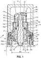
- the packaging and dispensing device 1 comprises a body 2, typically a bottle body, with a bottom 2a which defines a support base B, a container 4 which extends (entirely, essentially or in part) to inside the body 2 and makes it possible to store the liquid or viscous product 5 to be dispensed, a stopper element S, preferably made of thermoplastic material, assembled to the container 4 in a sealed manner and which forms part of a head 6 for dispensing or tip.
- the body 2 can be defined by a single piece of preferably rigid material, for example glass or plastic, opaque, translucent or transparent. Alternatively, all or part of body 2 can be made of metal.
- a coating may be provided to cover all or part of the outer face f2 of the side wall 2b of the body 2.
- the decorative coating may include any surface treatment compatible with the material of the body 2, for example lacquering on glass, metallization on plastic, anodization on aluminum, etc. and/ or any decoration by processes such as hot foil stamping, screen printing, pad printing, labeling, laser engraving, etc.
- the body 2 is mounted after having completely assembled an internal unit 25 which brings together a reservoir part R and a dispensing head 6 including a metering assembly 15.
- the container 4 delimits the reservoir from the reservoir part R.
- the complementary part of the reservoir part R is the dispensing head 6 which includes the dispensing functions (with the metering assembly 15) and the function of plugging the filling opening O of the container 4 (with a part forming a capping S).
- a contact obtained during assembly (after filling) between the stopper element S and the container 4 of the reservoir part R makes it possible to seal between an upper end 4a of the container 4, which is tubular and in practice circular section (without this being limiting), and the metering assembly 15.
- the filling opening O is thus closed in a sealed manner on the side of the upper end 4a which is typically circular, as clearly visible on the picture 2 .
- the closure element S here formed in one piece, is in continuous contact with the container 4 in an annular connection zone.
- the closure element S is preferably designed in one piece which includes a collar 106 for bearing on the top of the container 4 and/or a radial face provided to bear axially against an internal rim 4e provided on one face inside the wall 4b of the container 4. Such a part is designed separately from the body 7c of the pump 7.
- the head 6 can be mounted in a state preassembled, with the plugging element S which defines the bottom of this head 6, opposite an actuating part 10 of the metering assembly 15. As clearly visible on the figure 1 and 2 and 10 , the closure element S is only partially inserted into the internal volume V of the container 4.
- the circular shape is also particularly well suited to allow the container 4 to be extended axially by a head whose metering assembly 15 includes a metering pump 7.
- the central axis X around which extends longitudinally the container 4, can coincide with an axis A of the metering pump 7, in particular when the latter includes an axially movable element such as a piston.
- the head 6 is broken down here into a metering assembly 15 (including in particular the metering pump 7 and the actuating portion 10) arranged in the extension of the container 2, and a separate stopper element S which is typically inserted in part in the container 4.
- the tip or head 6 can be covered, partially or totally, by a cap 16.
- a narrower female part 16a here cylindrical, can equip the cap 16 internally, in order to allow this cap 16 to be attached to the head 6 by a plastic-plastic type radial contact between an internal face of the female part 16a (here provided with lugs or a bead 16b) and an upper connector 17 covering the top of the internal unit 25.
- An upper sleeve 18 of the upper connector 17 has for example an annular groove 18r on which the corresponding protruding relief of the cap 16 engages.
- the female part 16a can be more flexible or more elastically deformable than the rest of the cap, this female part 16 being connected by example by welding W to the wall 16c of the outer cap body.
- a metering pump 7 which has an inlet 7a is mounted in the head 6 forming the metering tip.
- the plugging element S forms a support piece for the metering pump 7, here from below.
- this plugging element S supports the metering pump 7 (and not the reverse), for example by maintaining it at a determined level on the side of the upper end 4a of the container 4.
- the inlet 7a of the pump 7 is defined at a first end of a distribution channel (not shown).
- the pump 7 is of the “airless” type, that is to say without air intake, with a rod 11a or equivalent mobile part actuated when an activator is pushed in, generally arranged in the upper part of the device. 1, thus allowing the fluid forming the product 5 to exit through a nozzle or similar diffusion member 14, or else to exit through an applicator member (in the case of an applicator tip).
- the metering pump 7 comprises a pump body 7c, here cylindrical and provided with an external collar 21.
- the insertion portion 12 (which is part of the body 7c) extends under the collar 21 to be housed in a conduit L (also cylindrical) of the closure element S.
- a retaining piece 26 is provided to extend annularly around the pump body 7c and to form an outer side face of the stationary part of the metering assembly 15.
- the retaining piece 26 extends longitudinally around of the duct L from a lower part 26b provided with a skirt J to an upper end part 26d.
- the upper end part 26d, tubular, can be engaged with the outer collar 21 formed on the metering pump 7, in the assembled state of the metering assembly 15.
- the outer collar 21 can rest on the face upper part of the retaining relief(s) 261 ( Fig. 7 ) which allow the maintenance of the pump 7.
- An optional annular part 22 can also be mounted on top of the collar 21, in order to close the upper opening O26 of the retaining part 26, while also coming into engagement against a rim or external reliefs of the pump body 7c, just above the external collar 21.
- the annular piece 22 also typically prevents access to a spring of the pump 7, by laterally covering this spring R7 under the actuating portion 10.
- the holding piece 26 can be defined by a section transition piece between the lower part 26b, wider than the upper end 4a of the container 4, and the upper end part 26d, narrower than the upper end 4a and provided with an inner face 260 from which retaining reliefs 261, 262 project radially inwards to engage axially on either side of the collar 21.
- the picture 2 shows the group, here formed by two assembly parts 11 and 26 (here without counting the optional cap 16 illustrated on the figure 1 ), making it possible to envelop the metering pump 7.
- the pusher member 11 is formed of a rigid part and slides while being guided in the pump body 7c.
- the tubular wall 11b of the pusher member 11 can also optionally be angularly guided by an internal guide surface 18c ( figure 1 ), here cylindrical, defined by the upper connector 17 which is mounted on the metering assembly 15.
- a constriction E which defines an outlet of the duct L of the plugging part S (on the side of the volume V) can form an annular bearing surface for a shoulder 12a of the insertion portion 12 which is formed close to the inlet 7a.
- An annular lip, typically conical, completes this constriction E to achieve sealing with the bottom of the pump 7.
- the operation of the metering pump 7 is of a kind known per se, by example with a piston secured to the rod 11a (configured to increase the pressure in a metering chamber), slidably mounted in a longitudinal distribution channel.
- a non-return valve provided on the side of the inlet 7a defines a hermetic separation between the interior volume V of the tank and the distribution channel of the pump 7.
- the rod 11a When the pusher member 11 is depressed, here in response to a vertical manual pressure exerted on the actuating part 10, the rod 11a is lowered at the same time as an internal actuating element (for example a piston) which actuates the distribution.
- an internal actuating element for example a piston
- a cap 16 of the type shown in the figure 1 is obviously withdrawn so that the upper surface of the actuating part 10 (here formed by a pusher member 11 having a tubular wall 11b which surrounds the spring R7) is exposed to be actuated.
- the dosing assembly 15 makes it possible to deliver a specific dose of the product 5, this dose being ejected by creating a vacuum inside the container 4.
- a sealed and mobile wall P4 typically provided at the bottom of the container 4, which moves upwards to compensate for the depression so as to bring the device back to ambient atmospheric pressure before the next activation.
- the section of this wall P4 is complementary to the tube defined by the container 4, and in particular circular in the example shown.
- the actuating part 10 is typically in the form of a pusher member 11, movable along a longitudinal axis which may be parallel to the longitudinal axis X (here a central axis) of the container 4.
- the pusher member 11 has a substantially tubular wall 11b and is connected from above to the upper end of the rod 11a.
- the plugging element S is integral with an insertion portion 12 which belongs to the metering pump 7. It is understood that the end 7a is part of the insertion portion 12 and can, according to an option, extend projecting relative to the stopper element S, in a direction opposite to the actuating part 10 (in practice: projecting downwards when the packaging and dispensing device 1 is in a vertical position with the bottom 2a which defines a support base B).
- the diffusion member 14 for example in the form of a nozzle, is in fluid communication with the outlet 7b to deliver and direct a dose of product.
- a dose delivered in a radial direction towards the outside other configurations are possible: for example with an outlet of the product oriented substantially axially or in a direction (typically non-vertical) forming any angle with the direction of elongation of the device 1.
- This diffusion member 14 extends transversely in a position adjacent to the actuating part 10 and follows the movement of the pusher member 11. Locking in a high position of the pusher member 11 can optionally be provided, for example with a stop contact when this pusher member 11 is turned to deviate from a predefined orientation of the diffusion member 14. A slot separating two abutment zones can thus allow the movement of the pusher member 11 according to the predefined orientation.
- the reservoir part R will now be detailed with reference to the figure 2 , 3 10 and 12 .
- Container 4 comprises at least one sealed and movable wall P4, which allows the volume V of the reservoir defined by container 4 to decrease as product 5 is consumed.
- Container 4 may have a stationary tubular wall 4b, preferably rigid, against which is mounted the sealed and movable wall P4.
- the container 4 forms the lower part of the internal unit 25, covered and protected by the body 2 which forms an external part visible in the device 1 for packaging and distribution.
- the container 4 When the body 2 is transparent, the container 4 can be seen.
- the container 4 can typically have a cylindrical or slightly tapered shape towards the opening 13 of the body and a piston 29 defines the sealed and movable wall P4. This is considered more aesthetic than a flexible pouch or similar container 4 with a leaktight and movable wall P4 which retracts due to the flexibility of the material used.
- the option with a piston 29 can be used with any category of covering/protection, provided that the body 2 does not present any constriction or narrowing of section limiting the passage section to dimensions smaller than that of the wall. 4b.
- the piston 29 has, for example, a circular section which makes it possible to ensure a good seal. It is then understood that the section of the rigid guide wall 4b is circular. Under the piston 29, it is optionally possible to provide an added bottom piece 4f (attached to the side wall 4b) and use at least one orifice 4d to maintain at a sufficient level the pressure exerted against a lower face 29a of the piston 29 opposite to the filling opening O in product 5.
- the piston 29 provides on the one hand a sealed separation and on the other hand maintains an identical pressure between the fluid product 5 contained in the tank and the air of the peripheral volume VP.
- the piston 29 may have a profile in correspondence with the lower surface 6a of the head 6 which extends inside the container 4, as clearly visible on the figure 1 .
- the piston 29 defines an internal cavity 29b, positioned centrally, to receive a projecting end of the duct forming the inlet 7a when the piston 29 is raised due to the consumption of the product 5. This makes it possible to to approach a total restitution of product 5 (for example approximately 95% or more of mass of product restored), with typically a suppression or strong reduction of the dead volume.
- the dynamic sealing achieved between the piston 29 and the side wall 4b can be achieved with a low friction force of the piston 29, in particular when the product 5 has a high viscosity. Indeed, the force of the user pressing the pusher member 11 must overcome the return spring R7, the viscosity of the cosmetic product and the friction of the piston 29.
- a very high geometric precision of the side wall 4b of the container 4 (and of the piston 29) is necessary if one wants to guarantee a given level of frictional force of the piston while obtaining sealing, which prohibits to give any decorative function to the container 4 (because the decorative functions typically involve heating or mechanical deformations which alter the integrity of the wall 4b).
- a slightly conical geometry of the wall 4b, with a widening towards the lower end 4c can participate in facilitating the insertion of the piston 29 without damage and obtaining a satisfactory seal.
- the insertion of the piston 29 during assembly can advantageously be done from below, on the side of the lower end 4c, which avoids having to make the piston 29 travel the entire height of the container 4 to reach its filling position, clearly visible on the figure 1 .
- the piston slides in the container 4 over a short distance and it is not damaged by friction over almost the entire length of the container 4. This reduces the risk of damaging the piston 29 (good dynamic seal during use of device 1).
- the leaktight and mobile wall P4 is defined by a flexible wall or a flexible pocket which can retract and/or deform to reduce the interior volume of the container 4.
- the wall P4 extends preferably opposite the end 4a which is rigid and which can be identical to what is represented on the picture 3 .
- a pressure equalization orifice 2d can be provided when the body 2 has a bottom 2a.
- the body 2 can be made of an opaque material so as not to make visible the folded and/or contracted state of the pouch or flexible portion of the container 4 as it is consumed in product 5.
- At least the part of the container 4 which forms the pocket is made of a flexible and impermeable material (and offering a good level of neutrality with respect to cosmetic or pharmaceutical formulas), for example made of polyethylene.
- the first contact zone 27 is, in this non-limiting example, obtained on the side of an inner annular portion of the upper end 4a of the container 4, while the second contact zone 28 is defined on the side of an outer annular portion from the upper end 4a.
- the plugging element S is already covered by the outer skirt J of the metering assembly 15 before closing the opening O in a sealed manner.
- the container 4 the wall P4 of which is mobile or flexible and retractable, be inserted through the opening 300 of the ring 24 from above, pressing axially on the internal rim RB.
- assembly of the container 4 is carried out with insertion of the rigid upper end 4a, from below the ring 24, for example by using a bayonet-type connection in the internal surface S24 of the ring 24, which opposes the depression of the container 4 during the assembly of the dispensing head 6 on the reservoir part R.
- the first contact zone 27 can be defined otherwise in variants, for example by an annular contact located on the outer side of the upper end 4a, closer to the opening 13 than the second contact zone 28. More generally, the first contact zone 27 can be chosen from the interior surface, the exterior surface, the upper surface, one of the two corners, or a combination of these surfaces of the upper end 4a.
- the annular surface forming the sealing zone can advantageously be formed on an internal face 104 flared by the upper end 4a and may have a sloping portion which extends radially inwards and towards the bottom 2a, from an upper radial portion.
- the insertable closure part 105 belonging to the closure element S is in annular radial sealing contact with the internal face 104 of the upper end 4a, so that the upper end 4a and the closure element S are connected by interlocking in a sealed manner.
- the first annular contact zone 27 is here defined on the side of a flange 106 of the plugging element S which is axially distal from the bottom 2a. In the example of the figure 1 , it can be seen that the flange 106 covers the internal face 104.
- a very good seal is generated.
- a rigid material for example the container 4 which is rigid, made for example of polypropylene, copolyster or polyamide, and the plugging element S which is flexible, made for example of low density or medium density polyethylene.
- the materials can be reversed (the container 4 possibly being at least locally more flexible than the stopper element S).
- the plugging element S and the container 4, facing each other are advantageously of cylindrical symmetry.
- no deformation of circularity at the level of the connection disturbs the uniformity of support of the two conical bearing surfaces one on the other.
- the axial annular contact at the level of the axial bearing edge 38 does not in itself provide sealing but serves to maintain a good level of radial compression at the level of the tapered bearing surfaces.
- the insertable closure part 105 comprises an insertion portion IP of substantially cylindrical section, between the collar 106 and a radial portion RP which is axially closer to the bottom 2a.
- the insertion portion IP of cylindrical section is inserted through the upper end 4a of the container 4 (and typically through the opening 300 of the ring 24).
- the insertion portion IP is coaxial, around the longitudinal axis A of the pump 7, with the duct L formed centrally in the plugging element S to house and seal around the metering pump 7.
- annular lip 23 of the plugging element S comes for example to conform by conical contact (for example same principle as for the conical bearing surface at the upper end 4a) with the end of the pump 7 which defines the inlet 7a.
- annular bead (not shown) is formed inside the duct L of the plugging element S, close to its upper axial end. This bead comes to engage on the body of the pump 7 close to its collar 21, therefore at its axially most rigid place.
- the plugging element S is protected on the side of its collar 106 by the holding part 26.
- the plugging element S and the holding part 26 belong to a stationary part of the metering assembly 15 which preferably realizes a sufficiently robust fixing on the container 4 to withstand a drop test (corresponding to a 1.5 m drop on a hard surface as in the test specified in the document ASTM D6344-04 (2009)), without breakage of the any of the parts of the internal unit 25 and without compromising the operation of the metering pump 7 or causing a break in the seal.
- the retaining part 26 is both capable of retaining the pump 7 axially, for example by cooperating with the flange 21 of the pump 7, and can delimit by the lower part 26b an annular groove 26g which houses the peripheral part of the stopper element S including the collar 106 as well as the upper end 4a.
- the retaining piece 26 has an inner skirt 26a which delimits, with the outer skirt J formed in the lower part 26b, the annular groove 26g.
- a surface of the closure element S which serves to define an annular contact zone 27 against an internal face of the container 4, at the level of the upper end 4a, can extend inside this annular groove 26g .
- the internal face 104 of the upper end 4a also extends into the groove 26g, so that a protected sealed connection is obtained, made between the upper end 4a of the container 4 and the portion d IP insertion extended by the collar 106.
- the inner skirt 26a extends from the radial portion 26f which defines the section transition, to an annular end placed lower than the contact zone 27 annular.
- the stopper element S delimits with the retaining part 26 a narrow annular groove 50 (belonging to the head 6), in which the axial bearing edge 38 of the upper end 4a is inserted.
- the upper end 4a can be enclosed in this annular groove 50, for example with a contact formed by the lower part 26b.
- the upper end 4a of the container 4 can be inserted between the lower part 26b and the insertion portion IP of the closure element S.
- the retaining part 26 is engaged with the pump 7, the collar 7c on the internal reliefs 261, 262 which can be defined by two pairs of lugs.
- a collar 26c located on the part which surrounds the end 4a, comes here into engagement between two lugs of the same pair, with an axial blocking.
- the external diameter D5 defined at the level of the collar may be greater than the diameter of the opening 300 and slightly greater than a spacing dimension between the lugs 240 of the ring 24 in order to be able to be housed and snapped into the ring 24 by elastic deformation.
- the retaining ring 24 makes it easy to connect the part with the reservoir R and the head 6 forming the dosing tip to one another.
- the ring 24 is mounted from below, as visible on the picture 2 , and is positioned, externally, at the same level as the container sealing zone 4 - sealing element S.
- the ring 24 performs on its own the axial stop function for the container 4, for example by an internal rim RB or suitable internal reliefs.
- the wall 4b comprises a collar, bead 400 or at least one relief (typically a projecting circumferential relief) to stop the sliding (downward or upward) of the ring 24 along the container 4.
- a bevelled upper face 240a may also be provided for the retaining relief(s) 262 ( Fig. 7 ) which prevent the pump 7 from being removed from the retaining part 26.
- a container 4 with a circular cross-section is advantageous for obtaining satisfactory performances of dynamic sealing at the level of a piston 29 and of static sealing at the level of the interface between the lower part with reservoir R and the head 6 (upper part of distribution).
- the container 4 can be centered with respect to the side wall 2b of the body 2, for example by correspondence of size and shape between the container 4 and a neck 20c formed at the upper end of the body 2, possibly by choosing the external diameter D4 of the container 4 almost identical (for example identical or very slightly less) to the diameter D' of the opening 13, defined here at the level of the upper edge 2c above the neck 20c.
- the retaining ring 24 can come to rest axially against the upper face of the edge 2c.
- any radially projecting annular relief or any arrangement with radial projections, formed on a periphery of the internal unit 25, may be suitable for forming a contact edge or flange against the upper end of the body 2, in order to stop the sliding stroke of a lower reservoir part R of the internal unit 25, during the assembly of the container 4 in the body 2.
- the ring 24 is held entirely outside the body 2, extending entirely above a plane of the opening 13.
- the retaining ring 24 can be inserted partially into the opening 13 .
- the retaining ring 24, of annular shape extends around an opening 300 which can form a passage orifice for the container 4.
- the container 4 can thus be kept at a distance from a bottom 2a of body 2 or at a predetermined relative distance from an annular lower edge of body 2.
- the annular bead 400 can be replaced by an additional piece added to the top of the container 4 or in the lateral upper zone thereof.
- a clipping operation of the ring 24 can possibly be provided, directly or indirectly on the container 4.
- the configuration of the parts is provided so that the container 4 is prevented from sinking into the body 2 during the positioning of the stopper element S (for example during an insertion in strength of the head 6, after filling). This is permitted here by the lower surface of the external bead 400 or similar projecting relief of the container 4 and the corresponding surface of the ring 24. It is understood that the ring 24 can provide moderate retention of the elements of the reservoir part R as shown. down the picture 2 (with the container 4 maintained integral with the body 2 during the intermediate handling and transport operations, which is a temporary situation), while in the situation after the final assembly by insertion of the head 6, the parts are inseparable to form an internal unit 25 that cannot be dismantled.
- the container 4 Before closing the opening O, the container 4 can be suspended by means of the ring 24, without axial support of the lower end 4c on the bottom 2a of the body. This allows a great freedom of realization of the shape of the bottom 2a of the body 2.
- the container 4 is for example inserted from above and comes to rest axially on the annular inner rim RB formed in the inner surface S24 of the ring 24.
- the ring 24 performs its holding function by axially blocking the grip edges 400, 26c of the reservoir part R and of the head 6.
- These gripping edges 400, 26c are here formed respectively by the container 4 and the retaining piece 26, as clearly visible on the figure 1 .
- these gripping edges 400, 26c come to engage in a housing of the retaining ring 24, formed by an internal hollow or between two reliefs 240 spaced axially from each other of the retaining ring 24.
- a housing can be located in an intermediate axial position, and at a distance, respectively between a lower edge 24a of the external face F24 of the ring, preferably cylindrical, and at least one upper edge 24b of this external face F24.
- the device has an outer side wall SW, here constituted by a tubular outer part 107 of the upper connector 17 and by the outer side face of the body 2.
- This outer side wall SW extends around the longitudinal axis (X), from the lower end of the body 2 to an annular upper edge 17b, 117b of the outer tubular part 107.
- the retaining ring 24 is covered by the outer side wall SW in an assembled state of the device 1.
- the outer side wall SW is heterogeneous, with for example a first rigid material constituting the body 2, for example in the form of a glass bottle, and a second rigid or semi-rigid material constituting the tubular outer part 107.
- the outer parts 1b and 1c of the device 1 have a continuity of geometry, and of section (substantially identical dimensions) in the zone surrounding the head 6 of distribution.
- the cap 16 typically forms a complementary part 1a which also extends these outer parts 1b and 1c, with a continuity of geometry and section.
- the upper connector 17, 117 is provided with one or more members for fixing a cap 16, preferably with such members placed in a tubular part constituting an upper sleeve 18, 118. With the cap 16 closed, this sleeve 18, 118 is not visible because it is narrower than the outer tubular part 107 delimiting the part 1b, and housed in an internal volume of the cap 16.
- the connector 117 also has an upper section 116 coaxial around the sleeve 118 and which extends the tubular outer part 107 upwards.
- the radial part 20, 117a extends radially outwards beyond the radial portion 26f to delimit, under this radial portion 20, 117a, a cylindrical housing wider than the diameter D5, which makes it possible to place the ring 24 radially between the lower part 26b of the retaining piece 26 and connector 17, 117.
- the radial part 20, 117a extends radially outwards from the sleeve 18, 118 as far as a tubular outer part 107 including first fixing means FM1 serving to retain and lock the body 2 to the both axially and in a direction of rotation, by cooperating with second fixing means FM2 provided on the body 2, typically in a part covered by a skirt 19 of the connector 17, 117.
- the upper connector 17 or 117 may comprise or consist of a part P17 which includes the fixing means FM1 to allow removable fixing of the body 2, by a relative rotational movement between the connector 17, 117 and the body 2.
- the part P17 referred to below as the main part, has the skirt 19 where the fixing means FM1 are formed.
- the skirt 19, of generally annular shape, extending to a lower annular edge from the radial part 20 (visible on the figure 1 ), has one or more flexible parts SP, here two flexible parts in the non-limiting case of Figures 8A-8B .
- These flexible parts SP can be made flexible by thinning the skirt J19 and/or by delimiting between two slots 81, 82, 83, 84 respectively. These flexible parts SP, during assembly on the attachment zones of the body 2 which is more rigid than the main part P17, and much more rigid than the flexible parts SP.
- Each flexible part SP constitutes a tongue, delimited between two vertical slots 81, 82 or 83, 84 and attached to the rest of the part P17 by a junction zone representing less than 90° on the circumference of the skirt 19.
- the main part P17 is typically made of elastically deformable plastic material.
- a part forming a hoop 70 can cover the skirt 19 by being fixed to the part P17 so as to be integral in rotation, around the longitudinal axis X, with this part P17.
- the part 70 may include an opening for the passage of the upper sleeve 18 formed by the part P17 and a radial portion 70a bordering this axial opening and extending to a circular line of junction with a tubular outer part 107 which laterally covers the skirt 19.
- the part 70 is optionally metallic, provided with a metallic or glass outer coating. It may be aluminum by way of non-limiting example.
- the diameter D70 of the axial opening is for example slightly greater than the external diameter of the upper sleeve 18.
- one or more E70 notches or notches may be provided which locally widen the axial opening and which make it possible to insert one or more axial projections R20 formed on the radial part 20 of the part P17.
- the axial projections R20 prevent the rotation of the part forming the hoop 70 (auxiliary part without contact with the unit 25) compared to the main room P17.
- a marking function for example in the form of an arrow indicating the direction of disassembly of the connector 17, can optionally be obtained thanks to the cutting of the notches E70 and/or the shape visible from above of the axial projections R20.
- the upper connector 17 or 117 surrounds the stationary part of the metering assembly 15 and also surrounds the pusher member 11, forming a duct, called in the following upper sleeve 18, 118, where this pusher member 11 can slide.
- the push member 11 can cover the upper portion/sleeve 18, 118 of the upper connector 17, 117, at least when it is actuated to dispense the product 5.
- it can be advantageous for it to be the push member 11 which slides inside the upper connector 17, 117 as in the case of the figure 1 or of FIG. 117, for example with a configuration making the pusher member 11 unremovable (possibly by means of an annular bead, ribs or lugs for retaining the pusher member 11). This last configuration is advantageous when it is desired to be able to guarantee that the circuit of product 5 will not break.
- the internal surface 18c of the sleeve 18, 118 allows the upper connector 17 to be positioned around the upper end part 26d, and more generally around the metering assembly 15, before the engagement of the upper connector 17 on the body 2.
- the upper connector 17, 117 may not tighten the receiver assembly 26, S nor the ring 24, so that a rotational force on the upper connector 17, 117 (relative rotation around the axis longitudinal X with respect to the tank part 1b) will not be taken up by these internal parts.
- the upper connector 17, 117 is for example positioned on the metering assembly 15, from above, by exerting a simple axial displacement, with no centering function. Indeed, the alignment between the container 4 and the head 6 can be achieved in the contact zone between the flared internal face 104 of the container 4 (typically forming a conical sealing surface) and the plugging element S. configuration of the endpiece/head 6, with in particular the retaining part 26 which covers the plugging element S, makes it possible to free this contact zone from any parasitic stress likely to affect the uniform distribution of the radial compression of the closure element S on the conical surface of the container 4 or other similar compression required to seal off the opening O.
- the upper connector 17, 117 can then be rotated with respect to the distribution head 6, which makes it possible to position, if necessary by rotation, fixing means FM1 of this connector 17, 117 next to access zones ZA ( figure 4 ) having an angular delimitation (typically less than or equal to 90° or 100°) and allowing an annular lower end 100 of the connector 17, 117 to be placed below a carnette 200 of the body, as will be described later.
- the placement under the carnette 200 of the annular lower end 100 can be carried out at the same time as the engagement in support/axial contact of the radial part 20, 117a on the radial portion 26f of the retaining part 26.
- the upper connector 17, tubular with a section transition permitted by the radial part 20, has a peripheral portion which extends longitudinally in an annular fashion from the outer edge 20a of the radial part 20, forming a skirt 19 with flexible part(s).
- a flexibility allowing radial movement of the skirt 19 of the connector 17, 117 can be advantageous to allow a coupling in rotation with locking, on a fixing zone of a rigid body 2.
- the external side wall SW is obtained by a rotational coupling between an external upper part of the body 2 and an internal lower part of the upper connector 17, 117, typically provided in the skirt 19 (preferably by selective use of the flexible parts SP to overcome rigid reliefs provided projecting, with respect to a bottom surface FC, on the external face of the body 2).
- connection means FM1 complementary to means FM2 are provided in the upper connector 17, 117, here on the side of an internal lateral face.
- a body 2 made in one piece may be preferred to define both the outer part 1c of the outer side wall SW and the fixing zone including the receiving means FM2 for the bayonet type connection. Vial forming this body is preferably made of glass.
- the bottle (or body 2) is of revolution around a longitudinal axis Y which typically coincides with the longitudinal axis X of the container 4 in the mounted state of the device 1.
- the bottle has for example a carnette 200 or portion of similar rim formed in a neck 20c which includes the upper annular edge 2c of the body 2.
- the neck 20c can advantageously be of low axial extension L20.
- a relatively small axial extension makes it possible to reduce the area of overlap between the body and the upper connector 17 or 117, and thus minimize the plastic material required in the design of the upper connector 17, 117, in particular by reducing the length of the skirt 19 (see figure 8A ) and by reducing, if necessary, the extension of the part forming the hoop 70 (see the figure 9 ).
- the neck 20c has a total height or axial extension L20, measured from the shoulder E2, of less than or equal to 15 mm.
- the second fastening means FM2 extend over this neck 20c with in particular retaining reliefs provided on a side surface portion of the neck 20c, in a position adjacent to the shoulder E2 of the bottle.
- the shoulder E2 extends transversely from the neck to reach the top of the outer part 1c (upper end of the wall 2b).
- the carnette 200 is discontinuous with notches forming axial passages or access zones ZA, distributed over the circumference, to allow the descent of the internal lugs R1, R2 of the upper connector 17, 117 to the level of the shoulder E2 (initial low axial position of the internal lugs R1, R2). From such a low axial position of the connector, it remains to turn the upper connector 17, 117 (here in the direction of clockwise, without this being limiting) relative to the body 2 or reciprocally the body 2 in the reverse direction of rotation, with respect to the upper connector 17, 117.
- the rotation is preferably of the type representing substantially a quarter turn (within plus or minus 10°).
- the card portions, separated by the access zones can be two in number, representing an angular sector between 80 and 105°, for example of the order of 95° (the access zone ZA then being able to represent an angular sector between 75 and 100°, for example approximately 85° in the non-limiting example of figures 4 to 6 ).
- the bottle or body 2 can be designed with reliefs and a delimitation of lateral cavities 201, 202, in order to obtain a pre-tightening then an end-of-travel locking, during the pivoting of the skirt 19.
- annular edge 2c of the body 2 is connected to the annular edge 2c of the body 2 by the engagement of the internal lugs R1, R2, under the radial projections or under the carnette 200 of this annular edge 2c.
- the neck 20c includes at least one lateral cavity 201, 202 for receiving a corresponding internal lug R1, R2 which forms part of the second fixing means FM2.
- the cavity 201 visible on the figure 6 is delimited axially between a portion 200a, 200b of the carnette 200 and the shoulder E2, and extends circumferentially between a termination zone ZT and an access duct CA with narrowing in section as we are approaching the retaining reliefs.
- Termination zone ZT may be elongated and/or include an abutment surface B1, B2 having a radially outer edge BR, such abutment surface B1, B2 being formed in a projecting projection 203, 204.
- each side cavity 201, 202 can function as a guide in which the tangential sliding is harder and harder, until it stops with the engagement of a so-called front end 19f (leading or proximal end) of an internal lug R1, R2 against the abutment surface B1, B2.
- two diametrically opposed internal lugs R1, R2 thus cooperate with two diametrically opposed abutment surfaces B1, B2 of the body 2, for a position where the neck 20c is covered by the skirt 19.
- each flexible part or parts SP of the skirt 19 deviate radially outwards because each of the internal lugs R1, R2 then covers one of the zone of termination where the projection 203, 204 extends.
- each flexible part SP folds slightly inwards, radially, at the end of travel, because each projection 203, 204 enters an intermediate hollow 19c present in the internal ergot R1, R2.
- the lateral cavity 201 between the access duct CA with section narrowing (here axial narrowing) and an end-of-travel region optionally delimited by a last relief DR, the presence of a notch C1 then of a projection 203 delimiting an abutment surface oriented towards the notch C1.
- the same configuration is typically used in the other lateral cavity 202, with a notch C2 preceding a projection 204 similar to projection 203 (cf. figure 5 ).
- Each notch C1, C2 here has a height, measured from the bottom surface FC, which is less than a depth of the lateral cavity, measured between the radially outer edge BR of the abutment surface B1, B2 and the bottom surface FC .
- the notch C1, C2 corresponds to a gradual bulge or bulge formed on the bottom surface FC, while the abutment surface B1, B2 may have an angle of the order of 90° with respect to the bottom surface. FC, as shown in figure 5 .
- the locked configuration can be obtained when each internal lug R1, R2, with an elongated shape in a circumferential direction, is placed in a corresponding lateral cavity 201, 202, extending on either side of a surface stop B1, B2 of the side cavity 201, 202, preferably by being inserted into the side cavity 201, 202 beyond a notch C1, C2 of said side cavity.
- the upper connector 17, 117 can thus be fixedly secured to the body 2 in the locked state of the bayonet-type connection.
- the upper connector 17 thus remains integral with the body 2 during use of the device 1. This makes it possible to use this upper connector 17 as a support for a cap 16.
- the skirt 19 of the upper connector 17, typically covered by the piece forming hoop 70 which is integral in rotation with skirt 19, can axially extend the outer face of body 2 with a perimeter of identical format and length (with surface continuity).
- the upper connector 17, which extends under the actuating portion 10, can also correspond to a hoop in the intermediate position between the body 2 and the cap 16.
- the upper connector 17 has, in this non-limiting example, a function covering the upper part of the device 1 in combination with the cap 16.
- the figure 11A shows the decoupling operation, by a movement of relative rotation illustrated by the arrow F to turn the upper connector 17 and allow the internal lugs 11, 12, typically provided in the flexible parts SP, to overcome the reliefs B1, B2, C1 , C2 in the opposite direction of the locking stroke.
- the skirt 19 can be disengaged from the connector 17 of the neck 20c, then move the connector 17 axially to remove it when the internal lugs R1, R2 are no longer placed under the portions 200a, 200b of the carnette 200.
- the projections R20 of the connector 17 and/or similar anti-corrosion reliefs rotation may optionally indicate the direction of rotation of the connector 17 allowing disassembly. Any other marking can optionally be used.
- the connector 17 functionally forms a primary cover, the optional cap 16 constituting a secondary cover which is detachably mounted on the primary cover.
- the internal unit 25 can then be removed by simple axial extraction, out of the body 2.
- a cap 16 When a cap 16 is provided, this can remain mounted on the upper connector 17 or be removed (which can allow a better grip in hand of the tubular part 107 to be rotated).
- the retaining ring 24 here has a cylindrical outer face F24, the outer surface of which is preferably smooth, so that any retention effect by the body 2 is eliminated.
- the ring 24 can be placed entirely above the body 2, so that gripping the internal unit 25 (by gripping the ring 24) can be facilitated.
- the body can be removed to uncover the reservoir part PR before removing the connector 17, knowing that the body 2 and the connector 17 are separable by movement in opposite directions for an unlocked configuration of the upper connector 17.
- a user can obtain the device 1 including its internal unit 25 and, at the same time, internal units 25' forming compatible cartridges or refills to be inserted internally between the body 2 and the upper connector 17 , 117.
- the tightness of all the internal units is obtained in the same way, so that the internal units 25, 25' can be stored for a long time without altering the product 5 (fluid or viscous content).
- the upper connector 117 also has a sleeve upper 118 similar to the sleeve 18 of the connector 17 of the embodiments shown in particular on the Figures 8A-8B .
- Such an upper connector 117 has many similarities with the upper connector 17 provided in the embodiment of the preceding figures and differs essentially in that the upper section 116 extends the outer face upwards to one end forming the edge 117b which surrounds the actuating portion 10, so that a cap 16 is not necessary.
- the actuating portion 10 also withdraws.
- the actuating portion 10 can be retained from above by one or more protruding interior portions or flange provided on the side of the upper edge 117b and mounted on the movable part of the pump 7 without retaining relief, this which makes it possible to separate the internal unit 25 from the connector 117 - actuation portion 10 assembly. Indeed, by raising the connector 117 while firmly holding the reservoir part R of the unit 25, the portion of actuation 10 of the rod 11a, without significant effort.
- the internal unit 25 after extraction from the body 2, in order to separate the pusher member 111 from the rest of the head 6 of distribution which belongs to the internal unit 25.
- the ring 24 provided in the device with the upper connector 117 of the figures 13 and 14 may be identical or very similar to that of the preceding figures. It is understood that the head 6 here has a push member 111 which can be mounted internally in an upper compartment defined by the upper tubular section 116. The transverse wall forming the radial portion 117a separates this compartment upper and a lower compartment in which the top of the reservoir part R is housed. relative to end 117b, in the non-actuated position. The actuation of the push member 111 can be facilitated thanks to a notch 117c formed at the upper end 117b of the upper connector 117 ( figure 14 ). This is ergonomic, by making it possible to increase the area of contact between a finger of the user and the push member 111.
- a slot 130 here opposite the notch 117c, can allow the outlet of the diffuser member 14 to project radially outwards beyond the outer face defined by the upper section 116, or to be flush relative to this face.
- the figure 14 shows a slot 130 which opens out at its upper end, such a slot 130 can also be placed differently, without opening out.
- the slot 130 is here vertical and makes it possible to guide the sliding without the possibility of significant rotation of the pusher member 111.
- the body 2, the upper connector 117 and optionally the push member 111 can be reused with a new internal unit, after disassembly/assembly operations (the principle illustrated in the diagram of the Figures 11A-11B remaining applicable).
- the filling opening O has a diameter D2 which may be substantially identical to the internal diameter D1 of the container 4 on the side of its lower end 4c, possibly less than D1, and preferably at least equal to 90%, or even 98% or 100% of D1.
- the use of a container 4 without a neck makes it possible not to slow down the filling operation.
- the diameter of the filling opening O is typically greater than 15 mm and generally exceeds half the diameter D or representative characteristic of the outer periphery of the body 2 at least close to the shoulder E2. More generally, the filling opening O may have a diameter at least equal to 75% of the diameter of the opening 300 of the ring 24.
- the body 2 is made in one piece.
- the side wall 2b of the body 2, tubular, can have a constant cross section as in the case of the figure 12 or include at least one bulge 60 in an intermediate part as in the case of the figure 10 .
- the shape of the section can also vary (for example with an oval section only at the level of a bulge).
- the body 2 can have any type of geometry with a circumference suitable for gripping and which exceeds the maximum circumference of the container 4, so as to avoid any contact radial between the container 4 and the side wall 2b, except for the area located above the shoulder E2 of the body 2. It is also understood that the ring 24 is located above the upper opening 13 of the body 2 without interfering with filling opening O.
- the device 1 can be compact and is well suited for dispensing the same precise doses of liquid or viscous product.
- the device 1 is typically in the form of a vial with a dosing head/dosing tip and designed particularly for cosmetic applications and other applications requiring a high degree of customization of the outer side wall SW.
- the device 1 is particularly well suited to an “airless” type metering pump 7 which reduces the risk of contamination while allowing almost total evacuation of the product 5. Between the distribution channel 8 of the pump 7 and the interior of the container 4, there is no venting possible, the ring 24 guaranteeing in this respect the maintenance of a seal. It is also understood that the device 1 has a very limited number of moving or flexible parts, so that it is particularly robust and remains effective after a large number of uses. The integrity around the container 4 and the pump 7 is maintained despite any shocks, which makes it possible to guarantee sealing.
- the container 4 and the dispensing head 6 can form an integrated sub-assembly, in the form of a pre-assembled unit, which can be installed (in one piece) between a body 2 with protection and covering function and an upper connector, typically a rigid body 2 and connector provided with one or more flexible parts incorporating reliefs or lugs for coupling in rotation on the upper fixing zone of the body.
- the user can therefore easily remove the internal unit, as shown in the figure 11A of the sub-assembly forming the external side wall SW, in order to reload the device 1 (replace the empty cartridge formed by the internal unit 25 with a full cartridge).
- This makes it possible to reuse the upper connector 17, 117 and the body 2 several times, these reusable parts possibly being finely elaborated and relatively expensive, and thus extending their useful life beyond the useful life of the product 5 contained in the container 4 of the internal unit 25.
- the figures show a container 4 made in two parts to facilitate the insertion of a piston 29, it is also possible to insert into the body 2 a container with a movable bottom.
- the holding part 26 can be replaced by an equivalent assembly of at least two parts having both an axial thrust effect on the plugging element S and holding the metering pump 7.
- the the internal unit 25 can have another type of dosing assembly 15, possibly with air inlet, for example in options with filtration of the incoming air which can circulate (in the form of filtered air if necessary) to the inside of the tank.
- the internal unit 25 may optionally have a linear guide relief along the body, for example on the ring 24, and/or any means of indexing in rotation, for example a peg or orifice for a peg, may be provided in a part of the body 2 in contact with the container 4 or the ring 24.
Landscapes
- Containers And Packaging Bodies Having A Special Means To Remove Contents (AREA)
- Closures For Containers (AREA)
- Feeding, Discharge, Calcimining, Fusing, And Gas-Generation Devices (AREA)
- Medical Preparation Storing Or Oral Administration Devices (AREA)
- Loading And Unloading Of Fuel Tanks Or Ships (AREA)
Claims (15)
- Vorrichtung (1) zur Verpackung und Abgabe eines Fluidprodukts (5), umfassend:- einen Körper (2), der hohl und mit einem Boden (2a) oder einem unteren Rand an einem unteren Ende des Körpers versehen ist;- einen Behälterteil (R), der einen Behälter (4) umfasst, der ein Innenvolumen (V) des Behälters begrenzt und sich vollständig in ein durch den Körper (2) definiertes Innenvolumen erstreckt, wobei der Behälter (4) eine Längsachse (X) und eine Öffnung (O) an einem axialen oberen Ende (4a) in Rohrform aufweist;- einen Kopf (6), der eine Dosiereinheit (15) des Typs ohne Lufteinlass und ein Verschlusselement (S) aufweist, das die Öffnung (O) verschließt, wobei die Dosiereinheit (15) eine Dosierpumpe (7) und einen beweglichen Betätigungsabschnitt (10) aufweist, um die Abgabe des Fluidprodukts (5) zu ermöglichen, wobei das Verschlusselement (S) eine Halterung der Dosiereinheit (15) bildet; und- ein oberes Verbindungselement (17; 117), an dem der Körper (2) in einer verriegelten Konfiguration des oberen Verbindungselements befestigt ist, wobei das obere Verbindungselement (17; 117) einen radialen Abschnitt (20; 117a) aufweist, der sich um einen Durchgangskanal für die Dosierpumpe (7) herum radial nach außen zu einem rohrförmigen äußeren Abschnitt (107) erstreckt, einschließlich erster Befestigungsmittel (FM1);wobei die Vorrichtung (1) eine äußere Seitenwand (SW) aufweist, die sich um die Längsachse (X) vom unteren Ende des Körpers (2) bis zu einem ringförmigen oberen Rand (17b, 117b) des röhrenförmigen äußeren Teils (107) erstreckt,dadurch gekennzeichnet, dass die Verpackungs- und Abgabevorrichtung (1) einen Haltering (24) aufweist, bevorzugt aus einem Stück gefertigt, der:- in Kontakt mit dem Körper (2) und axial beweglich in Bezug auf den Körper (2) in der entriegelten Konfiguration des oberen Verbindungselements (17; 117) montiert ist;- dazu angepasst und angeordnet ist, den Behälterteil (R) und den Kopf (6) unabhängig von der verriegelten oder nicht verriegelten Konfiguration des oberen Verbindungselements (17; 117) axial zwischen sich zu blockieren; und- in Eingriff mit den Eingriffsrändern (400, 26c), die an einer Außenseite des Behälters (4) und am Kopf verteilt sind, derart dass der Kopf (6), der Behälterteil (R) und der Haltering (24) eine vormontierte innere Einheit (25) der Vorrichtung (1) bilden, wobei der Haltering (24) in einem zusammengebauten Zustand der Vorrichtung (1) von der äußeren Seitenwand (SW) bedeckt ist, und dass- der Körper (2), der bevorzugt aus einem Stück gefertigt ist, zweite Befestigungsmittel (FM2) umfasst, die in dem zusammengebauten Zustand und für die Verriegelungskonfiguration axial mit den ersten Befestigungsmitteln (FM1) in Eingriff stehen, wobei die ersten Befestigungsmittel (FM1) und die zweiten Befestigungsmittel (FM2) eine lösbare Verbindung zwischen dem oberen Verbindungselement (17; 117) und dem Körper (2) bilden und wobei es in der Verriegelungskonfiguration möglich ist, die innere Einheit (25) in axialer Abstützung an einer unteren Innenfläche (F20) des genannten radialen Abschnitts (20; 117a) zu halten; und- wobei das obere Verbindungselement (17; 117) fest mit den zweiten Befestigungsmitteln (FM2) verbunden ist, durch eine Verriegelungswirkung, die durch ein Schwenken um die Längsachse (X) des einen relativ zum anderen zwischen dem oberen Verbindungselement (17; 117) und dem Körper (2) erfolgt.
- Vorrichtung nach Anspruch 1, wobei der Haltering (24) einstückig ausgeführt ist und den Körper (2) nur axial von oben berührt.
- Vorrichtung nach Anspruch 1 oder 2, wobei der Haltering (24) axial anliegend an einem oberen ringförmigen Rand (2c) des Körpers (2) ruht, wo eine obere Öffnung (13) mit allgemein kreisförmigem Querschnitt des Körpers (2) begrenzt ist.
- Vorrichtung nach Anspruch 3, wobei die obere Öffnung (13) einen Durchmesser (D') aufweist, der im Wesentlichen gleich einem Außendurchmesser (D4) des Behälters (4) ist.
- Vorrichtung nach einem der vorhergehenden Ansprüche, wobei der Haltering (24) eine zylindrische Außenseite (F24) aufweist, deren Außenfläche bevorzugt glatt ist, wobei die über die Außenseite des Behälters (4) und den Kopf (6) verteilten Eingriffsränder (400, 26c) in eine durch einen inneren Hohlraum zwischen zwei axial beabstandeten Rändern (240) des Halterings gebildete Aufnahme des Halterings (24) eingreifen, wobei sich die Aufnahme in der axialen Mittelposition und in einem Abstand zwischen einem unteren Rand (24a) der zylindrischen Außenfläche (F24) und wenigstens einem oberen Rand (24b) der zylindrischen Außenfläche (F24) befindet.
- Vorrichtung nach einem der vorhergehenden Ansprüche, wobei die ersten Befestigungsmittel (FM1) und die zweiten Befestigungsmittel (FM2) ein Verbindungssystem vom Bajonette-Typ bilden.
- Vorrichtung nach Anspruch 6, wobei das obere Verbindungselement (17; 117) wenigstens zwei innere Stifte (R1, R2) aufweist, die zur Herstellung der Bajonettverbindung dienen,
wobei das obere Verbindungselement (17; 117) ferner aufweist:- eine Außenschürze (19) mit wenigstens einem flexiblen Abschnitt (SP), bevorzugt in Form eines radial nach außen ausladenden Abschnitts, welcher bevorzugt im Vergleich zum Rest des oberen Verbindungselements (17; 117) verdünnt ist, und wobei alle oder ein Teil der ersten Befestigungsmittel (FM1) in dem wenigstens einen flexiblen Abschnitt (SP) angeordnet sind. - Vorrichtung nach Anspruch 7, wobei das obere Verbindungselement (17) einen Bundteil (70) aufweist, der die Außenschürze (19) des oberen Verbindungselements seitlich umhüllt, wobei der Bundteil (70) bevorzugt aus Metall besteht, mit einer äußeren Metall- oder Glasbeschichtung, und wobei wenigstens ein Antirotationsrelief (E70, R70) außen am oberen Verbindungselement (17) vorgesehen ist, bevorzugt am radialen Abschnitt (20; 117a), um eine relative Drehung um die Längsachse (X) zwischen dem Bundteil (70) und dem oberen Verbindungselement (17) zu verhindern.
- Vorrichtung nach einem der vorhergehenden Ansprüche, wobei der radiale Abschnitt (20; 117a) des oberen Verbindungselements (17; 117) ein Übergangsabschnitt ist zwischen:- einer oberen Hülse (18; 118), die in Bezug auf die Dosierpumpe (7) radial proximal ist;- und dem äußeren röhrenförmigen Abschnitt (107), der radial distal zu der Dosierpumpe (7) liegt,wobei sich die obere Hülse (18) und der äußere röhrenförmige Abschnitt (107) von dem radialen Abschnitt (20) in entgegengesetzten axialen Richtungen parallel zur Längsachse (X) entfernen.
- Vorrichtung nach einem der vorhergehenden Ansprüche, wobei der Körper (2) ein Fläschchen vom Typ mit Carnette (200) ist, das aus einem Stück gefertigt ist und die zweiten Befestigungsmittel (FM2) an einem seitlichen Oberflächenabschnitt eines Halses (20c) neben einer Schulter (22) des Fläschchens umfasst,
wobei das Fläschchen, das bevorzugt aus Glas gefertigt ist, wenigstens eine seitliche Aushöhlung (201, 202) zur Aufnahme eines inneren Stifts (R1, R2) umfasst, der in den zweiten Befestigungsmitteln (FM2) enthalten ist, wobei der Hohlraum (201, 202) axial zwischen einem Abschnitt der Carnette (200) und der Schulter (22) begrenzt ist, und sich in Umfangsrichtung zwischen einem Abschlussbereich (ZT), in dem eine Anschlagfläche (B1, B2) mit einer radial äußeren Kante (BR) ausgebildet ist, und einem Zugangskanal (CA) mit Querschnittsverengung erstreckt. - Vorrichtung nach Anspruch 10, wobei in dem seitlichen Hohlraum (201, 202) wenigstens ein Vorsprung (203, 204, C1, C2) vorhanden ist, der von einer Bodenfläche (FC) des seitlichen Hohlraums (201, 202) vorsteht, wobei ein Vorsprung davon eine Kerbe (C1, C2) bildet, die eine von der Bodenfläche (FC) aus gemessene Höhe hat, die kleiner als eine zwischen dem radial äußeren Rand (BR) des Anschlagfläche (B1, B2) und der Bodenfläche (FC) gemessenen Tiefe des Hohlraums ist, wobei jeder der Vorsprünge (203, 204, C1, C2) derart ausgebildet und angeordnet ist, dass er der Entriegelung der lösbaren Befestigung zwischen dem oberen Verbindungselement (17; 117) und dem Körper (2) entgegenwirkt, wobei die verriegelte Konfiguration erhalten wird, wenn jeder innere Stift (R1, R2) in einer entsprechenden seitlichen Aussparung (201, 202) angeordnet ist, indem er sich auf beiden Seiten der Anschlagfläche (B1, B2) der seitlichen Aussparung (201, 202) über die Kerbe (C1, C2) der seitlichen Aussparung hinaus erstreckt.
- Vorrichtung nach Anspruch 11, wobei das obere Verbindungselement (17; (117) wenigstens zwei innere Stifte (R1, R2) aufweist, die jeweils in Umfangsrichtung zwischen einem vorderen, bevorzugt schmalem Ende (19f) und einem hinteren Ende (19r) länglich geformt sind und jeweils eine Zwischenvertiefung (19c) aufweisen, zwischen dem vorderen Ende (19t) und dem hinteren Ende (19r), um in der verriegelten Konfiguration einen integral mit dem Fläschchen geformten Vorsprung (203, 204) aufzunehmen, der sich in der seitlichen Ausnehmung (201, 202) befindet und es ermöglicht, die Anschlagfläche (B1, B2) zu bilden.
- Vorrichtung nach einem der Ansprüche 1 bis 12, wobei der Haltering (24) frei um die Längsachse (X) drehbar ist, so dass während eines Einsetzens des Behälterteils (R) in den Körper (2) und in einem vollständig eingesetzten Zustand des Behälterteils (R), bei dem der Ring (24) axial an einer Anschlagfläche des Körpers (2) senkrecht zur Längsachse (X) anliegt, die innere Einheit (25) frei drehbar ist.
- Vorrichtung nach einem der Ansprüche 1 bis 12, wobei der Haltering (24) ein Mittel zur Drehindexierung in Bezug auf den Körper (2) aufweist, so dass die innere Einheit (25) in einem vollständig eingesetzten Zustand des Behälterteils (R), bei dem der Ring (24) axial an einer Anschlagfläche des Körpers (2) senkrecht zur Längsachse (X) anliegt, gegen Drehung blockiert ist.
- Kit zum Verpacken und Verteilen wenigstens eines Fluidprodukts (5), umfassend:- die Vorrichtung zur Verpackung und Abgabe (1), wie in einem der vorhergehenden Ansprüche beschrieben, wobei die innere Einheit (25) eine erste Kartusche bildet, die mit einem ersten Produkt gefüllt ist; und- eine zweite Kartusche, die mit einem zweiten Produkt gefüllt ist, wobei die zweite Kartusche durch eine weitere innere Einheit (25') gebildet wird, die der inneren Einheit (25) der ersten Kartusche entspricht,wobei der Haltering (24) jeder inneren Einheit (25, 25') einen äußeren Flansch bildet, der dafür vorgesehen ist, sich nach außen in Bezug auf den Behälter (4) zu erstrecken; wobei der Körper (2) und das obere Verbindungselement (17; 117), die durch eine Bewegung in entgegengesetzte Richtungen für eine entriegelte Konfiguration des oberen Verbindungselements (17; 117) voneinander trennbar sind, es ermöglichen, eine bestimmten Kartusche zu schützen, die beliebig aus der ersten Kartusche und der zweiten Kartusche gewählt ist, nach einem Einsetzen des Behälters (4) der bestimmten Kartusche in den Körper (2) und einer umfangmäßigen Umhüllung des Dosierungsabschnitts (15) der bestimmten Kartusche durch das obere Verbindungselement (17; 117) und für eine verriegelte Befestigungskonfiguration zwischen dem oberen Verbindungselement und dem Körper durch die Verwendung der lösbaren Befestigungsmittel, die die ersten Befestigungsmittel (FM1) und die zweiten Befestigungsmittel (FM2) umfassen.
Applications Claiming Priority (2)
| Application Number | Priority Date | Filing Date | Title |
|---|---|---|---|
| FR1872394A FR3089431B1 (fr) | 2018-12-05 | 2018-12-05 | Dispositif de conditionnement et distribution par dose d’un produit fluide, incluant un flacon reutilisable |
| PCT/FR2019/052805 WO2020115399A1 (fr) | 2018-12-05 | 2019-11-26 | Dispositif de conditionnement et distribution par dose d'un produit fluide, incluant un flacon reutilisable |
Publications (2)
| Publication Number | Publication Date |
|---|---|
| EP3890893A1 EP3890893A1 (de) | 2021-10-13 |
| EP3890893B1 true EP3890893B1 (de) | 2022-11-30 |
Family
ID=67107510
Family Applications (1)
| Application Number | Title | Priority Date | Filing Date |
|---|---|---|---|
| EP19868178.5A Active EP3890893B1 (de) | 2018-12-05 | 2019-11-26 | Vorrichtung zur aufbereitung eines fluidischen produkts and zur dosierten agbage des produkts, samt wiedervenwenbarer flasche |
Country Status (6)
| Country | Link |
|---|---|
| US (1) | US11471903B2 (de) |
| EP (1) | EP3890893B1 (de) |
| CN (1) | CN113272072B (de) |
| BR (1) | BR112021010876A2 (de) |
| FR (1) | FR3089431B1 (de) |
| WO (1) | WO2020115399A1 (de) |
Families Citing this family (12)
| Publication number | Priority date | Publication date | Assignee | Title |
|---|---|---|---|---|
| DE202019103061U1 (de) * | 2019-05-29 | 2020-09-01 | Louvrette Gmbh Design X Packaging | Vorrichtung zur Aufbewahrung und Abgabe einer flüssigen oder pastösen Masse |
| FR3109540B1 (fr) * | 2020-04-28 | 2022-04-08 | Aptar France Sas | Distributeur de produit fluide |
| US11382398B2 (en) | 2020-10-05 | 2022-07-12 | Samhwa Co., Ltd | Cosmetic container |
| FR3120359B1 (fr) * | 2021-03-05 | 2023-10-27 | Horus Pharma | Dispositif de conditionnement a systeme d’aeration integre |
| IT202100018110A1 (it) * | 2021-07-09 | 2023-01-09 | Lumson Spa | Dispositivo per contenere ed erogare sostanze fluide |
| IT202100018116A1 (it) * | 2021-07-09 | 2023-01-09 | Lumson Spa | Dispositivo di ricarica di sostanze fluide |
| KR102573274B1 (ko) * | 2021-10-08 | 2023-08-31 | 주식회사 삼화 | 튜브리스 토출 용기 |
| IT202200002894A1 (it) * | 2022-02-16 | 2023-08-16 | Erose S R L | Apparato per erogazione di un profumo |
| CH719816A1 (de) * | 2022-06-24 | 2023-12-29 | Alpla Werke Alwin Lehner Gmbh & Co Kg | System zum Verbinden eines Behälters mit einer Ausgabevorrichtung, Behälter und Aufnahmevorrichtung. |
| FR3143570B1 (fr) * | 2022-12-19 | 2024-12-20 | Oreal | Ensemble de conditionnement et de distribution de produit |
| IT202300009144A1 (it) * | 2023-05-08 | 2024-11-08 | Lumson Spa | Dispositivo di erogazione di una sostanza fluida |
| FR3148728B1 (fr) * | 2023-05-17 | 2025-06-13 | Chanel Parfums Beaute | Assemblage comportant un flacon, une frette esthétique et un système d’accrochage de la frette esthétique |
Family Cites Families (11)
| Publication number | Priority date | Publication date | Assignee | Title |
|---|---|---|---|---|
| US6341706B1 (en) * | 2000-06-01 | 2002-01-29 | Color Access, Inc. | Snap-on plastic neck for glass containers |
| GB0402692D0 (en) * | 2004-02-06 | 2004-03-10 | Glaxo Group Ltd | A fluid dispenser |
| DE102007046625B4 (de) * | 2007-09-27 | 2012-06-06 | Gaplast Gmbh | Vorrichtung zum getrennten Aufbewahren einer Substanz, vorzugsweise eines medizinischen oder pharmazeutischen Wirkstoffs, und einer Flüssigkeit und zum Mischen derselben vor dem Gebrauch |
| DE102008022595A1 (de) | 2007-10-25 | 2009-04-30 | Kessler, Reinhard, Dipl.-Ing. | Refill-Spender zur Abgabe pastöser Produkte aus Tuben |
| IT1391428B1 (it) | 2008-08-05 | 2011-12-23 | Lumson Spa | Dispositivo erogatore di sostanze fluide |
| GB201000601D0 (en) * | 2010-01-14 | 2010-03-03 | Rieke Corp | Pump dispensers |
| US9248462B2 (en) | 2011-12-01 | 2016-02-02 | Yonwoo Co., Ltd. | Airless pump system |
| US9296003B2 (en) * | 2014-02-26 | 2016-03-29 | Aptar Italia S.P.A. | Dispensing pump |
| FR3018033B1 (fr) * | 2014-02-28 | 2016-03-25 | Dior Christian Parfums | Dispositif de conditionnement d'une recharge d'un produit |
| FR3026392B1 (fr) * | 2014-09-30 | 2016-09-30 | Albea Le Treport | Flacon remplissable de distribution d’un produit fluide |
| FR3042181B1 (fr) * | 2015-10-08 | 2020-02-28 | Qualipac | Dispositif de conditionnement et distribution par dose d'un produit fluide |
-
2018
- 2018-12-05 FR FR1872394A patent/FR3089431B1/fr active Active
-
2019
- 2019-11-26 WO PCT/FR2019/052805 patent/WO2020115399A1/fr not_active Ceased
- 2019-11-26 CN CN201980088123.6A patent/CN113272072B/zh not_active Expired - Fee Related
- 2019-11-26 US US17/311,189 patent/US11471903B2/en active Active
- 2019-11-26 BR BR112021010876-9A patent/BR112021010876A2/pt not_active Application Discontinuation
- 2019-11-26 EP EP19868178.5A patent/EP3890893B1/de active Active
Also Published As
| Publication number | Publication date |
|---|---|
| EP3890893A1 (de) | 2021-10-13 |
| US20220023901A1 (en) | 2022-01-27 |
| CN113272072A (zh) | 2021-08-17 |
| FR3089431A1 (fr) | 2020-06-12 |
| WO2020115399A1 (fr) | 2020-06-11 |
| BR112021010876A2 (pt) | 2021-08-31 |
| CN113272072B (zh) | 2022-08-05 |
| US11471903B2 (en) | 2022-10-18 |
| FR3089431B1 (fr) | 2021-01-01 |
Similar Documents
| Publication | Publication Date | Title |
|---|---|---|
| EP3890893B1 (de) | Vorrichtung zur aufbereitung eines fluidischen produkts and zur dosierten agbage des produkts, samt wiedervenwenbarer flasche | |
| WO2017060631A1 (fr) | Dispositif de conditionnement et distribution par dose d'un produit fluide | |
| EP3999245B1 (de) | Vorrichtung zum verschliessen eines behälters eines flüssigen bis pastösen produkts und mit einer solchen vorrichtung verschlossene nachfüllpackung | |
| EP1044893B1 (de) | Vorrichtung zum unmittelbaren Vermischen von mindestens zwei Produkten, von denen eines ein Pulver ist | |
| EP1626813B1 (de) | Ausgabevorrichtung für fluide produkte und verfahren zur montage einer solchen ausgabevorrichtung | |
| EP1572375B1 (de) | Manuell betätigte dosierpumpe | |
| EP3094419B1 (de) | Flüssigproduktbehälter und spender | |
| EP1472007B1 (de) | Spender für fliessfähige medien mit einer pumpe | |
| EP2095882B1 (de) | Flakon für die Aufnahme eines flüssigen oder pastenartigen Produktes | |
| FR2887937A1 (fr) | Pompe pour la distribution de fluides | |
| WO2021079060A1 (fr) | Dispositif de conditionnement d'un produit cosmetique et assemblage du dispositif utilisant un connecteur ayant deux faces internes de fixation | |
| EP3199244B1 (de) | Vorrichtung zum ansaugen von flüssigen produkten in einem spender | |
| EP2092985B1 (de) | Behälter mit Steigrohr | |
| EP2977110B1 (de) | Nachfüllbarer spender für flüssigprodukt | |
| WO2014199095A1 (fr) | Distributeur de produit fluide rechargeable. | |
| FR3142751A1 (fr) | Ensemble poche et conteneur pour stocker un produit fluide et dispositif de stockage et de distribution du produit fluide | |
| EP3525937B1 (de) | Verteiler mit füllkartusche | |
| EP4297910B1 (de) | Reservoir sowie fluidabgabevorrichtung | |
| WO2025083372A1 (fr) | Recharge de produit fluide | |
| FR3154334A1 (fr) | Recharge de produit fluide | |
| FR3138416A1 (fr) | Distributeur d’un produit fluide, recharge associée et réceptacle associé | |
| FR3138417A1 (fr) | Recharge pour réceptacle de produit fluide et réceptacle associé | |
| FR2974792A1 (fr) | Distributeur de produit fluide. |
Legal Events
| Date | Code | Title | Description |
|---|---|---|---|
| STAA | Information on the status of an ep patent application or granted ep patent |
Free format text: STATUS: UNKNOWN |
|
| STAA | Information on the status of an ep patent application or granted ep patent |
Free format text: STATUS: THE INTERNATIONAL PUBLICATION HAS BEEN MADE |
|
| PUAI | Public reference made under article 153(3) epc to a published international application that has entered the european phase |
Free format text: ORIGINAL CODE: 0009012 |
|
| STAA | Information on the status of an ep patent application or granted ep patent |
Free format text: STATUS: REQUEST FOR EXAMINATION WAS MADE |
|
| 17P | Request for examination filed |
Effective date: 20210604 |
|
| AK | Designated contracting states |
Kind code of ref document: A1 Designated state(s): AL AT BE BG CH CY CZ DE DK EE ES FI FR GB GR HR HU IE IS IT LI LT LU LV MC MK MT NL NO PL PT RO RS SE SI SK SM TR |
|
| DAV | Request for validation of the european patent (deleted) | ||
| DAX | Request for extension of the european patent (deleted) | ||
| GRAP | Despatch of communication of intention to grant a patent |
Free format text: ORIGINAL CODE: EPIDOSNIGR1 |
|
| STAA | Information on the status of an ep patent application or granted ep patent |
Free format text: STATUS: GRANT OF PATENT IS INTENDED |
|
| INTG | Intention to grant announced |
Effective date: 20220707 |
|
| GRAS | Grant fee paid |
Free format text: ORIGINAL CODE: EPIDOSNIGR3 |
|
| GRAA | (expected) grant |
Free format text: ORIGINAL CODE: 0009210 |
|
| STAA | Information on the status of an ep patent application or granted ep patent |
Free format text: STATUS: THE PATENT HAS BEEN GRANTED |
|
| AK | Designated contracting states |
Kind code of ref document: B1 Designated state(s): AL AT BE BG CH CY CZ DE DK EE ES FI FR GB GR HR HU IE IS IT LI LT LU LV MC MK MT NL NO PL PT RO RS SE SI SK SM TR |
|
| REG | Reference to a national code |
Ref country code: CH Ref legal event code: EP Ref country code: GB Ref legal event code: FG4D Free format text: NOT ENGLISH |
|
| REG | Reference to a national code |
Ref country code: AT Ref legal event code: REF Ref document number: 1534270 Country of ref document: AT Kind code of ref document: T Effective date: 20221215 |
|
| REG | Reference to a national code |
Ref country code: IE Ref legal event code: FG4D Free format text: LANGUAGE OF EP DOCUMENT: FRENCH |
|
| REG | Reference to a national code |
Ref country code: DE Ref legal event code: R096 Ref document number: 602019022722 Country of ref document: DE |
|
| REG | Reference to a national code |
Ref country code: LT Ref legal event code: MG9D |
|
| REG | Reference to a national code |
Ref country code: NL Ref legal event code: MP Effective date: 20221130 |
|
| PG25 | Lapsed in a contracting state [announced via postgrant information from national office to epo] |
Ref country code: SE Free format text: LAPSE BECAUSE OF FAILURE TO SUBMIT A TRANSLATION OF THE DESCRIPTION OR TO PAY THE FEE WITHIN THE PRESCRIBED TIME-LIMIT Effective date: 20221130 Ref country code: PT Free format text: LAPSE BECAUSE OF FAILURE TO SUBMIT A TRANSLATION OF THE DESCRIPTION OR TO PAY THE FEE WITHIN THE PRESCRIBED TIME-LIMIT Effective date: 20230331 Ref country code: NO Free format text: LAPSE BECAUSE OF FAILURE TO SUBMIT A TRANSLATION OF THE DESCRIPTION OR TO PAY THE FEE WITHIN THE PRESCRIBED TIME-LIMIT Effective date: 20230228 Ref country code: LT Free format text: LAPSE BECAUSE OF FAILURE TO SUBMIT A TRANSLATION OF THE DESCRIPTION OR TO PAY THE FEE WITHIN THE PRESCRIBED TIME-LIMIT Effective date: 20221130 Ref country code: FI Free format text: LAPSE BECAUSE OF FAILURE TO SUBMIT A TRANSLATION OF THE DESCRIPTION OR TO PAY THE FEE WITHIN THE PRESCRIBED TIME-LIMIT Effective date: 20221130 Ref country code: ES Free format text: LAPSE BECAUSE OF FAILURE TO SUBMIT A TRANSLATION OF THE DESCRIPTION OR TO PAY THE FEE WITHIN THE PRESCRIBED TIME-LIMIT Effective date: 20221130 |
|
| REG | Reference to a national code |
Ref country code: AT Ref legal event code: MK05 Ref document number: 1534270 Country of ref document: AT Kind code of ref document: T Effective date: 20221130 |
|
| PG25 | Lapsed in a contracting state [announced via postgrant information from national office to epo] |
Ref country code: RS Free format text: LAPSE BECAUSE OF FAILURE TO SUBMIT A TRANSLATION OF THE DESCRIPTION OR TO PAY THE FEE WITHIN THE PRESCRIBED TIME-LIMIT Effective date: 20221130 Ref country code: PL Free format text: LAPSE BECAUSE OF FAILURE TO SUBMIT A TRANSLATION OF THE DESCRIPTION OR TO PAY THE FEE WITHIN THE PRESCRIBED TIME-LIMIT Effective date: 20221130 Ref country code: LV Free format text: LAPSE BECAUSE OF FAILURE TO SUBMIT A TRANSLATION OF THE DESCRIPTION OR TO PAY THE FEE WITHIN THE PRESCRIBED TIME-LIMIT Effective date: 20221130 Ref country code: IS Free format text: LAPSE BECAUSE OF FAILURE TO SUBMIT A TRANSLATION OF THE DESCRIPTION OR TO PAY THE FEE WITHIN THE PRESCRIBED TIME-LIMIT Effective date: 20230330 Ref country code: HR Free format text: LAPSE BECAUSE OF FAILURE TO SUBMIT A TRANSLATION OF THE DESCRIPTION OR TO PAY THE FEE WITHIN THE PRESCRIBED TIME-LIMIT Effective date: 20221130 Ref country code: GR Free format text: LAPSE BECAUSE OF FAILURE TO SUBMIT A TRANSLATION OF THE DESCRIPTION OR TO PAY THE FEE WITHIN THE PRESCRIBED TIME-LIMIT Effective date: 20230301 |
|
| PG25 | Lapsed in a contracting state [announced via postgrant information from national office to epo] |
Ref country code: NL Free format text: LAPSE BECAUSE OF FAILURE TO SUBMIT A TRANSLATION OF THE DESCRIPTION OR TO PAY THE FEE WITHIN THE PRESCRIBED TIME-LIMIT Effective date: 20221130 |
|
| PG25 | Lapsed in a contracting state [announced via postgrant information from national office to epo] |
Ref country code: SM Free format text: LAPSE BECAUSE OF FAILURE TO SUBMIT A TRANSLATION OF THE DESCRIPTION OR TO PAY THE FEE WITHIN THE PRESCRIBED TIME-LIMIT Effective date: 20221130 Ref country code: RO Free format text: LAPSE BECAUSE OF FAILURE TO SUBMIT A TRANSLATION OF THE DESCRIPTION OR TO PAY THE FEE WITHIN THE PRESCRIBED TIME-LIMIT Effective date: 20221130 Ref country code: EE Free format text: LAPSE BECAUSE OF FAILURE TO SUBMIT A TRANSLATION OF THE DESCRIPTION OR TO PAY THE FEE WITHIN THE PRESCRIBED TIME-LIMIT Effective date: 20221130 Ref country code: DK Free format text: LAPSE BECAUSE OF FAILURE TO SUBMIT A TRANSLATION OF THE DESCRIPTION OR TO PAY THE FEE WITHIN THE PRESCRIBED TIME-LIMIT Effective date: 20221130 Ref country code: CZ Free format text: LAPSE BECAUSE OF FAILURE TO SUBMIT A TRANSLATION OF THE DESCRIPTION OR TO PAY THE FEE WITHIN THE PRESCRIBED TIME-LIMIT Effective date: 20221130 Ref country code: AT Free format text: LAPSE BECAUSE OF FAILURE TO SUBMIT A TRANSLATION OF THE DESCRIPTION OR TO PAY THE FEE WITHIN THE PRESCRIBED TIME-LIMIT Effective date: 20221130 |
|
| PG25 | Lapsed in a contracting state [announced via postgrant information from national office to epo] |
Ref country code: SK Free format text: LAPSE BECAUSE OF FAILURE TO SUBMIT A TRANSLATION OF THE DESCRIPTION OR TO PAY THE FEE WITHIN THE PRESCRIBED TIME-LIMIT Effective date: 20221130 Ref country code: AL Free format text: LAPSE BECAUSE OF FAILURE TO SUBMIT A TRANSLATION OF THE DESCRIPTION OR TO PAY THE FEE WITHIN THE PRESCRIBED TIME-LIMIT Effective date: 20221130 |
|
| REG | Reference to a national code |
Ref country code: DE Ref legal event code: R097 Ref document number: 602019022722 Country of ref document: DE |
|
| PLBE | No opposition filed within time limit |
Free format text: ORIGINAL CODE: 0009261 |
|
| STAA | Information on the status of an ep patent application or granted ep patent |
Free format text: STATUS: NO OPPOSITION FILED WITHIN TIME LIMIT |
|
| 26N | No opposition filed |
Effective date: 20230831 |
|
| PG25 | Lapsed in a contracting state [announced via postgrant information from national office to epo] |
Ref country code: SI Free format text: LAPSE BECAUSE OF FAILURE TO SUBMIT A TRANSLATION OF THE DESCRIPTION OR TO PAY THE FEE WITHIN THE PRESCRIBED TIME-LIMIT Effective date: 20221130 |
|
| PG25 | Lapsed in a contracting state [announced via postgrant information from national office to epo] |
Ref country code: IT Free format text: LAPSE BECAUSE OF FAILURE TO SUBMIT A TRANSLATION OF THE DESCRIPTION OR TO PAY THE FEE WITHIN THE PRESCRIBED TIME-LIMIT Effective date: 20221130 |
|
| REG | Reference to a national code |
Ref country code: DE Ref legal event code: R119 Ref document number: 602019022722 Country of ref document: DE |
|
| REG | Reference to a national code |
Ref country code: CH Ref legal event code: PL |
|
| PG25 | Lapsed in a contracting state [announced via postgrant information from national office to epo] |
Ref country code: MC Free format text: LAPSE BECAUSE OF FAILURE TO SUBMIT A TRANSLATION OF THE DESCRIPTION OR TO PAY THE FEE WITHIN THE PRESCRIBED TIME-LIMIT Effective date: 20221130 |
|
| PG25 | Lapsed in a contracting state [announced via postgrant information from national office to epo] |
Ref country code: LU Free format text: LAPSE BECAUSE OF NON-PAYMENT OF DUE FEES Effective date: 20231126 |
|
| PG25 | Lapsed in a contracting state [announced via postgrant information from national office to epo] |
Ref country code: CH Free format text: LAPSE BECAUSE OF NON-PAYMENT OF DUE FEES Effective date: 20231130 |
|
| GBPC | Gb: european patent ceased through non-payment of renewal fee |
Effective date: 20231126 |
|
| PG25 | Lapsed in a contracting state [announced via postgrant information from national office to epo] |
Ref country code: MC Free format text: LAPSE BECAUSE OF FAILURE TO SUBMIT A TRANSLATION OF THE DESCRIPTION OR TO PAY THE FEE WITHIN THE PRESCRIBED TIME-LIMIT Effective date: 20221130 Ref country code: LU Free format text: LAPSE BECAUSE OF NON-PAYMENT OF DUE FEES Effective date: 20231126 Ref country code: CH Free format text: LAPSE BECAUSE OF NON-PAYMENT OF DUE FEES Effective date: 20231130 |
|
| REG | Reference to a national code |
Ref country code: BE Ref legal event code: MM Effective date: 20231130 |
|
| REG | Reference to a national code |
Ref country code: IE Ref legal event code: MM4A |
|
| PG25 | Lapsed in a contracting state [announced via postgrant information from national office to epo] |
Ref country code: IE Free format text: LAPSE BECAUSE OF NON-PAYMENT OF DUE FEES Effective date: 20231126 Ref country code: DE Free format text: LAPSE BECAUSE OF NON-PAYMENT OF DUE FEES Effective date: 20240601 |
|
| PG25 | Lapsed in a contracting state [announced via postgrant information from national office to epo] |
Ref country code: GB Free format text: LAPSE BECAUSE OF NON-PAYMENT OF DUE FEES Effective date: 20231126 |
|
| PG25 | Lapsed in a contracting state [announced via postgrant information from national office to epo] |
Ref country code: BE Free format text: LAPSE BECAUSE OF NON-PAYMENT OF DUE FEES Effective date: 20231130 |
|
| PG25 | Lapsed in a contracting state [announced via postgrant information from national office to epo] |
Ref country code: IE Free format text: LAPSE BECAUSE OF NON-PAYMENT OF DUE FEES Effective date: 20231126 Ref country code: GB Free format text: LAPSE BECAUSE OF NON-PAYMENT OF DUE FEES Effective date: 20231126 Ref country code: DE Free format text: LAPSE BECAUSE OF NON-PAYMENT OF DUE FEES Effective date: 20240601 Ref country code: BE Free format text: LAPSE BECAUSE OF NON-PAYMENT OF DUE FEES Effective date: 20231130 |
|
| PG25 | Lapsed in a contracting state [announced via postgrant information from national office to epo] |
Ref country code: BG Free format text: LAPSE BECAUSE OF FAILURE TO SUBMIT A TRANSLATION OF THE DESCRIPTION OR TO PAY THE FEE WITHIN THE PRESCRIBED TIME-LIMIT Effective date: 20221130 |
|
| PG25 | Lapsed in a contracting state [announced via postgrant information from national office to epo] |
Ref country code: BG Free format text: LAPSE BECAUSE OF FAILURE TO SUBMIT A TRANSLATION OF THE DESCRIPTION OR TO PAY THE FEE WITHIN THE PRESCRIBED TIME-LIMIT Effective date: 20221130 |
|
| PG25 | Lapsed in a contracting state [announced via postgrant information from national office to epo] |
Ref country code: CY Free format text: LAPSE BECAUSE OF FAILURE TO SUBMIT A TRANSLATION OF THE DESCRIPTION OR TO PAY THE FEE WITHIN THE PRESCRIBED TIME-LIMIT; INVALID AB INITIO Effective date: 20191126 |
|
| PG25 | Lapsed in a contracting state [announced via postgrant information from national office to epo] |
Ref country code: HU Free format text: LAPSE BECAUSE OF FAILURE TO SUBMIT A TRANSLATION OF THE DESCRIPTION OR TO PAY THE FEE WITHIN THE PRESCRIBED TIME-LIMIT; INVALID AB INITIO Effective date: 20191126 |
|
| PG25 | Lapsed in a contracting state [announced via postgrant information from national office to epo] |
Ref country code: TR Free format text: LAPSE BECAUSE OF FAILURE TO SUBMIT A TRANSLATION OF THE DESCRIPTION OR TO PAY THE FEE WITHIN THE PRESCRIBED TIME-LIMIT Effective date: 20221130 |
|
| PGFP | Annual fee paid to national office [announced via postgrant information from national office to epo] |
Ref country code: FR Payment date: 20251030 Year of fee payment: 7 |