EP3892833B1 - Turbomaschine mit öltank, der mit sensoren versehen ist - Google Patents
Turbomaschine mit öltank, der mit sensoren versehen ist Download PDFInfo
- Publication number
- EP3892833B1 EP3892833B1 EP21167092.2A EP21167092A EP3892833B1 EP 3892833 B1 EP3892833 B1 EP 3892833B1 EP 21167092 A EP21167092 A EP 21167092A EP 3892833 B1 EP3892833 B1 EP 3892833B1
- Authority
- EP
- European Patent Office
- Prior art keywords
- oil
- turbomachine
- tank
- temperature
- sensor
- Prior art date
- Legal status (The legal status is an assumption and is not a legal conclusion. Google has not performed a legal analysis and makes no representation as to the accuracy of the status listed.)
- Active
Links
Images

Classifications
-
- F—MECHANICAL ENGINEERING; LIGHTING; HEATING; WEAPONS; BLASTING
- F01—MACHINES OR ENGINES IN GENERAL; ENGINE PLANTS IN GENERAL; STEAM ENGINES
- F01M—LUBRICATING OF MACHINES OR ENGINES IN GENERAL; LUBRICATING INTERNAL COMBUSTION ENGINES; CRANKCASE VENTILATING
- F01M11/00—Component parts, details or accessories, not provided for in, or of interest apart from, groups F01M1/00 - F01M9/00
- F01M11/0004—Oilsumps
-
- F—MECHANICAL ENGINEERING; LIGHTING; HEATING; WEAPONS; BLASTING
- F01—MACHINES OR ENGINES IN GENERAL; ENGINE PLANTS IN GENERAL; STEAM ENGINES
- F01D—NON-POSITIVE DISPLACEMENT MACHINES OR ENGINES, e.g. STEAM TURBINES
- F01D25/00—Component parts, details, or accessories, not provided for in, or of interest apart from, other groups
- F01D25/18—Lubricating arrangements
- F01D25/20—Lubricating arrangements using lubrication pumps
-
- F—MECHANICAL ENGINEERING; LIGHTING; HEATING; WEAPONS; BLASTING
- F01—MACHINES OR ENGINES IN GENERAL; ENGINE PLANTS IN GENERAL; STEAM ENGINES
- F01M—LUBRICATING OF MACHINES OR ENGINES IN GENERAL; LUBRICATING INTERNAL COMBUSTION ENGINES; CRANKCASE VENTILATING
- F01M11/00—Component parts, details or accessories, not provided for in, or of interest apart from, groups F01M1/00 - F01M9/00
- F01M11/10—Indicating devices; Other safety devices
-
- F—MECHANICAL ENGINEERING; LIGHTING; HEATING; WEAPONS; BLASTING
- F02—COMBUSTION ENGINES; HOT-GAS OR COMBUSTION-PRODUCT ENGINE PLANTS
- F02C—GAS-TURBINE PLANTS; AIR INTAKES FOR JET-PROPULSION PLANTS; CONTROLLING FUEL SUPPLY IN AIR-BREATHING JET-PROPULSION PLANTS
- F02C7/00—Features, components parts, details or accessories, not provided for in, or of interest apart form groups F02C1/00 - F02C6/00; Air intakes for jet-propulsion plants
- F02C7/06—Arrangements of bearings; Lubricating
-
- F—MECHANICAL ENGINEERING; LIGHTING; HEATING; WEAPONS; BLASTING
- F16—ENGINEERING ELEMENTS AND UNITS; GENERAL MEASURES FOR PRODUCING AND MAINTAINING EFFECTIVE FUNCTIONING OF MACHINES OR INSTALLATIONS; THERMAL INSULATION IN GENERAL
- F16N—LUBRICATING
- F16N29/00—Special means in lubricating arrangements or systems providing for the indication or detection of undesired conditions; Use of devices responsive to conditions in lubricating arrangements or systems
-
- F—MECHANICAL ENGINEERING; LIGHTING; HEATING; WEAPONS; BLASTING
- F01—MACHINES OR ENGINES IN GENERAL; ENGINE PLANTS IN GENERAL; STEAM ENGINES
- F01M—LUBRICATING OF MACHINES OR ENGINES IN GENERAL; LUBRICATING INTERNAL COMBUSTION ENGINES; CRANKCASE VENTILATING
- F01M11/00—Component parts, details or accessories, not provided for in, or of interest apart from, groups F01M1/00 - F01M9/00
- F01M11/10—Indicating devices; Other safety devices
- F01M2011/14—Indicating devices; Other safety devices for indicating the necessity to change the oil
- F01M2011/142—Indicating devices; Other safety devices for indicating the necessity to change the oil by considering speed, e.g. revolutions per minute [RPM]
-
- F—MECHANICAL ENGINEERING; LIGHTING; HEATING; WEAPONS; BLASTING
- F01—MACHINES OR ENGINES IN GENERAL; ENGINE PLANTS IN GENERAL; STEAM ENGINES
- F01M—LUBRICATING OF MACHINES OR ENGINES IN GENERAL; LUBRICATING INTERNAL COMBUSTION ENGINES; CRANKCASE VENTILATING
- F01M11/00—Component parts, details or accessories, not provided for in, or of interest apart from, groups F01M1/00 - F01M9/00
- F01M11/10—Indicating devices; Other safety devices
- F01M2011/14—Indicating devices; Other safety devices for indicating the necessity to change the oil
- F01M2011/1453—Indicating devices; Other safety devices for indicating the necessity to change the oil by considering oil quantity
-
- F—MECHANICAL ENGINEERING; LIGHTING; HEATING; WEAPONS; BLASTING
- F05—INDEXING SCHEMES RELATING TO ENGINES OR PUMPS IN VARIOUS SUBCLASSES OF CLASSES F01-F04
- F05D—INDEXING SCHEME FOR ASPECTS RELATING TO NON-POSITIVE-DISPLACEMENT MACHINES OR ENGINES, GAS-TURBINES OR JET-PROPULSION PLANTS
- F05D2260/00—Function
- F05D2260/80—Diagnostics
-
- F—MECHANICAL ENGINEERING; LIGHTING; HEATING; WEAPONS; BLASTING
- F05—INDEXING SCHEMES RELATING TO ENGINES OR PUMPS IN VARIOUS SUBCLASSES OF CLASSES F01-F04
- F05D—INDEXING SCHEME FOR ASPECTS RELATING TO NON-POSITIVE-DISPLACEMENT MACHINES OR ENGINES, GAS-TURBINES OR JET-PROPULSION PLANTS
- F05D2260/00—Function
- F05D2260/98—Lubrication
-
- F—MECHANICAL ENGINEERING; LIGHTING; HEATING; WEAPONS; BLASTING
- F05—INDEXING SCHEMES RELATING TO ENGINES OR PUMPS IN VARIOUS SUBCLASSES OF CLASSES F01-F04
- F05D—INDEXING SCHEME FOR ASPECTS RELATING TO NON-POSITIVE-DISPLACEMENT MACHINES OR ENGINES, GAS-TURBINES OR JET-PROPULSION PLANTS
- F05D2270/00—Control
- F05D2270/30—Control parameters, e.g. input parameters
- F05D2270/303—Temperature
-
- F—MECHANICAL ENGINEERING; LIGHTING; HEATING; WEAPONS; BLASTING
- F16—ENGINEERING ELEMENTS AND UNITS; GENERAL MEASURES FOR PRODUCING AND MAINTAINING EFFECTIVE FUNCTIONING OF MACHINES OR INSTALLATIONS; THERMAL INSULATION IN GENERAL
- F16N—LUBRICATING
- F16N2200/00—Condition of lubricant
- F16N2200/04—Detecting debris, chips, swarfs
-
- F—MECHANICAL ENGINEERING; LIGHTING; HEATING; WEAPONS; BLASTING
- F16—ENGINEERING ELEMENTS AND UNITS; GENERAL MEASURES FOR PRODUCING AND MAINTAINING EFFECTIVE FUNCTIONING OF MACHINES OR INSTALLATIONS; THERMAL INSULATION IN GENERAL
- F16N—LUBRICATING
- F16N2210/00—Applications
- F16N2210/02—Turbines
-
- F—MECHANICAL ENGINEERING; LIGHTING; HEATING; WEAPONS; BLASTING
- F16—ENGINEERING ELEMENTS AND UNITS; GENERAL MEASURES FOR PRODUCING AND MAINTAINING EFFECTIVE FUNCTIONING OF MACHINES OR INSTALLATIONS; THERMAL INSULATION IN GENERAL
- F16N—LUBRICATING
- F16N2250/00—Measuring
- F16N2250/04—Pressure
-
- F—MECHANICAL ENGINEERING; LIGHTING; HEATING; WEAPONS; BLASTING
- F16—ENGINEERING ELEMENTS AND UNITS; GENERAL MEASURES FOR PRODUCING AND MAINTAINING EFFECTIVE FUNCTIONING OF MACHINES OR INSTALLATIONS; THERMAL INSULATION IN GENERAL
- F16N—LUBRICATING
- F16N2250/00—Measuring
- F16N2250/08—Temperature
-
- F—MECHANICAL ENGINEERING; LIGHTING; HEATING; WEAPONS; BLASTING
- F16—ENGINEERING ELEMENTS AND UNITS; GENERAL MEASURES FOR PRODUCING AND MAINTAINING EFFECTIVE FUNCTIONING OF MACHINES OR INSTALLATIONS; THERMAL INSULATION IN GENERAL
- F16N—LUBRICATING
- F16N2250/00—Measuring
- F16N2250/30—Dialectricum
-
- Y—GENERAL TAGGING OF NEW TECHNOLOGICAL DEVELOPMENTS; GENERAL TAGGING OF CROSS-SECTIONAL TECHNOLOGIES SPANNING OVER SEVERAL SECTIONS OF THE IPC; TECHNICAL SUBJECTS COVERED BY FORMER USPC CROSS-REFERENCE ART COLLECTIONS [XRACs] AND DIGESTS
- Y02—TECHNOLOGIES OR APPLICATIONS FOR MITIGATION OR ADAPTATION AGAINST CLIMATE CHANGE
- Y02T—CLIMATE CHANGE MITIGATION TECHNOLOGIES RELATED TO TRANSPORTATION
- Y02T50/00—Aeronautics or air transport
- Y02T50/60—Efficient propulsion technologies, e.g. for aircraft
Definitions
- the invention deals with the measurement of properties of the oil in a turbomachine oil reservoir.
- the invention also proposes a turbomachine, in particular an aircraft turbojet or an aircraft turboprop, comprising an instrumented oil tank.
- the invention finally discusses a method for analyzing the data collected in the reservoir.
- a turbojet engine uses oil during its operation.
- the oil is used for lubricating or cooling certain components of the turbomachine, as well as for heating areas subject to frost. Additionally, the oil can be pressurized for the purpose of operating hydraulic cylinders.
- the oil tank commonly has a window for viewing the level of stored liquid. It includes a transparent window allowing an internal control of the tank by simple visual check. This check can only be done during a stopover or during a maintenance operation.
- the patent application FR 3 035 919 A1 describes a method for monitoring oil consumption in a turbomachine by determining the mass of oil present in the tank.
- the mass of oil is calculated by measuring the pressure in one or more low points of the tank.
- the document EP 3 282 104 A1 describes a system that measures the level of oil in a reservoir by measuring the electrical capacitance of the oil. Capacitive measurement is known to be an alternative to resistive measurement, the latter having a temperature-limited operating range.
- the values obtained are reliable except that they are based on nominal conditions of oil quality and operating temperature.
- the quality of the oil is not measured in situ and the time of use of the oil (its aging) causes its physico-chemical properties to vary, the precision of the measurements is no longer as precise after a certain time of use of the oil as it would be under nominal conditions .
- the object of the invention is to improve the reliability of the measurements of the properties of the oil in a turbomachine tank.
- the invention also aims to provide a compact and reliable technical solution.
- the subject of the invention is a turbomachine comprising a lubrication circuit with an oil reservoir, the reservoir comprising: a chamber intended to contain the oil; an inlet and an outlet respectively allowing the oil to enter the chamber and to be extracted therefrom; sensors, arranged in the chamber, in the inlet and/or in the outlet; the sensors comprising a sensor for measuring the electrical resistance of the oil, a temperature sensor for measuring the temperature of the oil and a sensor of the quantity of ferromagnetic debris present in the oil, the turbomachine being remarkable in that it comprises a calculation unit receiving the data measured by the sensors, the calculation unit determining, on the basis of the measurements of the sensors, at least one of the elements among: the quality of the oil, the level of the oil , the degree of pollution of the oil, or the mass of the oil, the turbomachine further comprising a fan and a fan rotation speed sensor, which communicates its measurements to the calculation unit, the latter determining the remaining operating time of the turbomachine before a lack of oil as a function of the speed
- the reservoir is particularly advantageous for these measurements because it has both portions where the fluid flows (inlet or outlet) and portions without eddies.
- the reservoir also includes an area that is always occupied by oil.
- the calculation unit can be attached to or incorporated into the tank and can take the form of a compact box, bringing together all the electronics necessary to calculate and communicate the values obtained to the cockpit.
- the calculation unit can be remote (FADEC for example).
- the ferromagnetic debris sensor is placed in the inlet or in the outlet. It is thus possible to benefit from the movement of the oil on entry or exit, to maximize the capture of ferromagnetic debris.
- the tank includes a capacitive sensor to measure the electric capacity of the oil.
- the fan rotation speed sensor is a pressure sensor placed in the inlet of the tank.
- the invention also relates to a method for monitoring the properties of the oil in a tank of a turbomachine, the method comprising the following steps: (a) measuring the temperature of the oil in the tank; (b) measuring the electrical resistance of the oil in the reservoir; (c) measuring the electrical capacitance of the oil in the reservoir; (d) determination of oil quality as a function of electrical resistance and temperature; (e) determination of oil level as a function of electrical capacity, electrical resistance and temperature.
- the method further comprises the following steps: (f) measuring the quantity of ferromagnetic debris in the oil in the reservoir; (g) determination of the oil pollution rate as a function of the temperature and the quantity of ferromagnetic debris.
- the invention makes it possible to consolidate the various data coming from the sensors in order to obtain more reliable values under all the conditions of use of the turbomachine.
- the implementation is also made compact by the integration of several sensors in the tank. This minimizes the wiring requirements or the power of wireless transmitters. Also, this prevents the sensors from being arranged in the circuit at places where they would form an obstacle to the flow of the oil flow. Maintenance of the measuring system is also simplified.
- the tank therefore constitutes a “smart tank” provided with a calculation unit integrated or connected to a calculation unit, which acts as a “health monitoring” for the oil.
- the axial direction corresponds to the direction along the axis of rotation of the turbomachine.
- the radial direction is perpendicular to the axis of rotation.
- Upstream and downstream refer to the main flow direction of the stream in the turbomachine.
- the height and the vertical aspect are considered for the tank in the normal direction of assembly.
- FIG. 1 schematically represents a turbomachine, in this case a turbofan engine.
- the turbojet engine 2 comprises a first compression level, called low-pressure compressor 4, a second compression level, called high-pressure compressor 6, a combustion chamber 8 and one or more levels of turbines 10.
- the mechanical power of the turbines 10 is transmitted via shafts to the rotor 12 and sets in motion the two compressors 4 and 6.
- the latter comprise several rows of associated rotor blades to rows of stator vanes.
- the rotation of the rotor around its axis of rotation 14 thus makes it possible to generate an air flow and to gradually compress the latter until it enters the combustion chamber 8.
- a fan 16 is coupled to the rotor 12 and generates an air flow which is divided into a primary flow 18 passing through the various aforementioned levels of the turbomachine, and a secondary flow 20 passing through an annular duct.
- Reduction means 22 can reduce the speed of rotation of the fan 16 and/or of the low-pressure compressor 4 with respect to the speed of the associated turbine 10.
- the rotor 12 comprises several coaxial shafts 24 supported by bearings 26.
- the cooling and/or the lubrication of the bearings 26 and of the optional reducer 22 are ensured by a lubrication circuit 28.
- the lubrication circuit 28 can incidentally supply actuators such as cylinders (not shown).
- the lubrication circuit 28 may also include a heat exchanger 30 to cool the oil, the temperature of which may exceed 200°C. These temperatures amplify the corrosiveness of the oil towards seals and polymer parts.
- the lubrication circuit 28 may include pipes 32 in which the oil circulates under the action of pumps. To this end, the lubrication circuit 28 may include a lubrication unit 34.
- the lubrication unit 34 can be directly mounted on an accessory box of the turbojet engine 2.
- the lubrication unit 34 is a unit composed of a one-piece body which accommodates several hydraulic functions such as several pumps and filters for example. It pressurizes the oil taken from a tank 36 and distributes it in the engine components to be lubricated before reconditioning it (cooling and filtering) and returning it to the tank 36.
- One of the pipes 32 can make it possible to recover the oil lubricating the reducer 22 and return it to the reservoir 36.
- the reservoir 36 can be fixed to the nacelle of the turbomachine, or to a compressor casing. Reservoir 36 can be placed between two annular walls guiding the primary 18 or secondary 20 flows. In order to optimize its useful volume, reservoir 36 is essentially elongated while following a generally curved shape. This curvature allows installation between two curved and close partitions. The tank can in particular be positioned close to a hot source where its temperature can reach 100°C.
- the operation of the turbomachine involves wear of the bearings 26 and of the pumps of the lubrication unit 34. This wear releases metallic particles into the lubrication circuit 28. These particles are also found in the oil in the reservoir and can modify the physico-chemical properties of the oil.
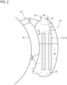
- FIG. 2 is a sectional view of the oil tank 36.
- the reservoir 36 is in this example assembled by means of assembly elements 38 to a casing 40 of the compressor 4, 6.
- Reservoir 36 comprises a chamber 42, part 44 of which is essentially occupied by air or an essentially gaseous phase (with oil droplets in suspension) and part 46 is essentially occupied by oil (with impurities ).
- part 46 is usually below part 44 in the direction of the figure 2 .
- the reservoir comprises at least one inlet 48, illustrated here in an upper part of the reservoir 36.
- the reservoir comprises at least one outlet 50, illustrated here in a lower part of the reservoir 36.
- the inlet 48 and the outlet 50 allow the circulation of the oil. They can be connected to the lubrication unit 34. The position of the inlet 48 and the outlet 50 can be adapted according to the surrounding elements.
- Reservoir 36 is shown schematically. This may include (not shown) a deaerator, a vent, an oil separator, as well as check valves and/or valves in particular associated with the inlet 48 and/or the outlet 50.
- Reservoir 36 includes a number of sensors 52, 54, 56, 58, 60 connected to a computing unit 62. Sensors 52, 54, 56, 58, 60 communicate with computing unit 62 by means of a physical or wireless connection.
- the tank wall can act as an electrical conductor. Sensors 52, 54, 56, 58, 60 can use different technologies to measure different physical quantities. Each of the sensors 52, 54, 56, 58, 60 is optional.
- the capacitive sensor participating in the measurement of the oil level can be replaced by another sensor using another technology.
- a single calculation unit 62 is provided, in order to simplify the needs for communication with the other control units of the aircraft, and in order to limit the bulk in the tank 36.
- the unit 62 can be arranged on the wall of the reservoir 36, or even in reservoir 36, i.e. in chamber 42.
- the calculation unit 62 can be remote from the tank and be integrated into the FADEC (full authority digital engine (or electronics) control) of the aircraft.
- FADEC full authority digital engine (or electronics) control
- the sensors 52 and 54 measure the electrical capacitance C and the electrical resistance R between two respective electrodes (one of which may be formed by the wall of the reservoir).
- the electrodes can be of the type detailed in the request EP 3 282 104 A1 .
- the electrodes are bathed in oil and return to the calculation unit 62 the resistance and electrical capacitance values.
- Calculation unit 62 also receives a temperature value T measured by a temperature sensor 56 and a debris concentration value in the oil Cd measured by a sensor detecting ferromagnetic debris 58.
- the temperature sensor 56 can be arranged in a lower part 46 of the tank 36 so as to be in a calm and flooded part of the tank 36. Alternatively, it can be arranged on a float.
- the debris sensor 58 can be arranged at the inlet 48 of the tank 36. It can be of the type described in the application BE2019/5850 ( PCT/EP2020/081945 ), that is to say a magnet surrounded by a coil, the whole potentially isolated in a non-magnetic envelope.
- the calculation unit 62 establishes, from the measurements of the sensors, estimates of: the quality q of the oil, the level n of the oil, the level of pollution tp of the oil and the mass m of the oil.
- the quality q of the oil is evaluated from the measurement of the resistance R and the temperature T.
- the electrical resistance is a good indicator of the quality of the oil.
- the oil the present invention corrects the quality values as a function of temperature: it is possible that a poor quality oil and a good quality oil share the same electrical resistance value but at different temperatures. Thus, by taking the temperature into account, the quality value can be corrected.
- the quality can be a score resulting from a calculation taking into account the resistance and the temperature.
- the resistance variations according to a temperature gradient can be calculated and used to establish the quality of the oil.
- the quality may reflect fuel in oil pollution.
- Table 1 below is an example of considering resistance and temperature to determine oil quality. ⁇ i>Table 1 ⁇ /i> 100°C 110°C ... 240°C 250°C R1 q 1,100 q 1.110 ... q 1,240 q 1,250 R2 q 2,100 q 2.110 ... q 2,240 q 2,250 ... ... ... ... ... ... R3 q 3,100 q 3.110 ... q 3,240 q 3,250 R4 q 4,100 q 4.110 ... q 4,240 q 4,250
- R1 to R4 can be of the order of ten M ⁇ .
- This type of analysis can also be applied to the determination of the values of the oil level n, of the pollution rate tp of the oil and of the mass m of the oil.
- the oil level n is determined by the calculation unit 62 by taking into account the electrical capacitance C, the electrical resistance R and the temperature T. If it is known to estimate the oil level by a measurement of electrical capacitance or electrical resistance, the present invention makes it possible to correct the values obtained by combining these two measurements and also by taking the temperature into account.
- the pollution rate tp of the oil is calculated from a concentration of ferromagnetic debris Cd and corrected according to the temperature. Indeed, a high level of debris at low temperature may be normal, whereas a level of debris at high temperature may reveal premature wear of certain mechanical parts of the turbomachine. Thus, the present invention proposes a measurement of the pollution of the oil by the measurement of debris enriched by the measurement of temperature.
- the mass m of the oil can be calculated from the oil level n and the temperature.
- oil may contain impurities (metal debris, gas bubbles), relating its mass to volume is not completely accurate.
- the mass values are more accurate.
- the density varies with the temperature and it is therefore advisable to consider the density of the oil which corresponds to its temperature. Also, the oil present elsewhere in the circuit must be taken into account. This can be constant or linked to the rotational speed of the motor.
- Sensor measurements can be made continuously or at a given frequency. Following the calculation of the mass m of oil for various successive measurements, it is possible to deduce the variations of the mass over time. Mass variations reflect oil consumption (or the amount lost). This consumption is, as a first approximation, proportional to the speed of rotation N of the turbomachine.
- the operating time dt available before the oil runs out can be calculated.
- the remaining flight time, for a given rotational speed (or a pre-established rotational speed pattern) can be determined.
- the calculations are similar to those used to estimate the distance remaining to be traveled in a motor vehicle before running out of gas.
- the speed of rotation N of the turbomachine can be measured at the level of the fan 16, or of one of the shafts 24 of transmission. Alternatively, an image of the speed of rotation is perceived by the pressure at the inlet 48 of the reservoir 36, measured by a pressure sensor 60.
- the pressure measurement gives an indication of the "gulping" at the reservoir inlet. Indeed, when the mass of oil is evaluated solely from the oil level, estimation errors appear in the event of gulping. It is therefore useful to detect it.
Landscapes
- Engineering & Computer Science (AREA)
- General Engineering & Computer Science (AREA)
- Mechanical Engineering (AREA)
- Chemical & Material Sciences (AREA)
- Combustion & Propulsion (AREA)
- Lubrication Details And Ventilation Of Internal Combustion Engines (AREA)
Claims (7)
- Eine Turbomaschine (2), die einen Schmierkreislauf (28) mit einem Öltank (36) umfasst, wobei der Öltank (36) Folgendes umfasst:- eine Kammer (42) zur Aufnahme des Öls;- einen Einlass (48) und einen Auslass (50), durch die das Öl in die Kammer (42) eintreten bzw. aus der Kammer austreten kann; und- Sensoren (52, 54, 56, 58, 60), die in der Kammer (42), in dem Einlass (48) und/oder dem Auslass (50) angeordnet sind;wobei die Sensoren (52, 54, 56, 58, 60) einen Sensor (54) zur Messung des elektrischen Widerstands des Öls, einen Temperatursensor (56) zur Messung der Öltemperatur und einen Sensor (58) zur Erfassung der Menge an ferromagnetischen Ablagerungen im Öl umfassen,die Turbomaschine (2) eine Recheneinheit (62) umfasst, die die von den Sensoren (52, 54, 56, 58, 60) gemessenen Daten empfängt, wobei die Recheneinheit (62) auf der Grundlage der Messungen der Sensoren (52, 54, 56, 58, 60) mindestens eines der folgenden Merkmale bestimmt: Ölqualität (q), Ölstand (n), Ölverschmutzungsrate (tp) oder Ölmasse (m),dadurch gekennzeichnet, dass die Turbomaschine außerdem ein Gebläse (16) und einen Drehzahlsensor (N) zur Erfassung der Drehzahl des Gebläses (16) umfasst, der seine Messungen an die Recheneinheit (62) übermittelt, wobei diese die verbleibende Betriebszeit (dt) der Turbomaschine (2) vor dem Ölmangel anhand der Drehzahl (N) und der Ölmasse (m) bestimmt.
- Eine Turbomaschine (2) nach Anspruch 1, dadurch gekennzeichnet, dass der ferromagnetische Trümmersensor (58) im Einlass (48) oder im Auslass (50) angeordnet ist.
- Eine Turbomaschine (2) nach Anspruch 1 oder 2, dadurch gekennzeichnet, dass der Öltank einen kapazitiven Sensor (52) zur Messung der elektrischen Kapazität des Öls enthält.
- Eine Turbomaschine nach einem der Ansprüche 1 bis 3, dadurch gekennzeichnet, dass der Drehzahlsensor (N) des Gebläses (16) ein im Einlass (48) des Öltanks (36) angeordneter Druck-(p)-Sensor (60) ist.
- Das Verfahren zur Überwachung der Eigenschaften des Öls in einem Öltank (36), dadurch gekennzeichnet, dass es ein Verfahren zur Überwachung der Eigenschaften des Öls in einem Tank einer Turbomaschine (2) nach einem der Ansprüche 1 bis 4 darstellt, wobei das Verfahren Folgendes umfasst:(a) Messung der Temperatur (T) des Öls in dem Öltank (36);(b) Messung des elektrischen Widerstands (R) des Öls in dem Öltank (36);(c) fakultative Messung der elektrischen Kapazität (C) des Öls im Öltank (36);(d) Bestimmung der Ölqualität (q) auf der Grundlage des elektrischen Widerstands (R) und der Temperatur (T);(e) Bestimmung des Ölstands (n) auf der Grundlage des elektrischen Widerstands (R) und der Temperatur (T) und möglicherweise der elektrischen Kapazität (C).
- Das Verfahren nach Anspruch 5, umfasst außerdem:(f) Messung der Menge an ferromagnetischen Ablagerungen (Cd) im Öl im Öltank (36);(g) Bestimmen der Ölverschmutzungsrate (tp) auf der Grundlage der Temperatur (T) und der Menge an ferromagnetischen Ablagerungen (Cd).
- Das Verfahren nach einem der Ansprüche 5 oder 6, ferner umfassend:(h) Bestimmen der Ölmasse (m) auf der Grundlage des Ölstands (n) und der Temperatur (T);(i) das Messen der Drehzahl (N) der Turbomaschine (2);(j) Bestimmen der verbleibenden Betriebszeit (dt) der Turbomaschine (2), bevor das Öl ausgeht, auf der Grundlage der Masse (m) und der Drehzahl (N).
Applications Claiming Priority (1)
| Application Number | Priority Date | Filing Date | Title |
|---|---|---|---|
| BE20205228A BE1028195B1 (fr) | 2020-04-08 | 2020-04-08 | Reservoir d’huile de turbomachine |
Publications (2)
| Publication Number | Publication Date |
|---|---|
| EP3892833A1 EP3892833A1 (de) | 2021-10-13 |
| EP3892833B1 true EP3892833B1 (de) | 2023-05-31 |
Family
ID=70456691
Family Applications (1)
| Application Number | Title | Priority Date | Filing Date |
|---|---|---|---|
| EP21167092.2A Active EP3892833B1 (de) | 2020-04-08 | 2021-04-07 | Turbomaschine mit öltank, der mit sensoren versehen ist |
Country Status (2)
| Country | Link |
|---|---|
| EP (1) | EP3892833B1 (de) |
| BE (1) | BE1028195B1 (de) |
Families Citing this family (2)
| Publication number | Priority date | Publication date | Assignee | Title |
|---|---|---|---|---|
| US12055430B2 (en) * | 2022-11-21 | 2024-08-06 | Honeywell International Inc. | Fluid level sensor for a toroid-shaped tank |
| FR3152544A1 (fr) * | 2023-09-06 | 2025-03-07 | Safran Aircraft Engines | Dispositif de détection de carburant dans l’huile par analyse de phase gazeuse |
Family Cites Families (11)
| Publication number | Priority date | Publication date | Assignee | Title |
|---|---|---|---|---|
| JP3196792B2 (ja) * | 1992-12-25 | 2001-08-06 | 株式会社東海理化電機製作所 | 液面レベル検出装置 |
| JPH11270787A (ja) * | 1998-03-19 | 1999-10-05 | Tennex Corp | エンジンオイルの劣化判定装置 |
| US7581434B1 (en) * | 2003-09-25 | 2009-09-01 | Rockwell Automation Technologies, Inc. | Intelligent fluid sensor for machinery diagnostics, prognostics, and control |
| GB201116173D0 (en) * | 2011-09-20 | 2011-11-02 | Rolls Royce Plc | Oil sensor |
| US9389215B2 (en) * | 2011-09-23 | 2016-07-12 | Mastinc | Multi-modal fluid condition sensor platform and system thereof |
| MX364907B (es) * | 2014-05-21 | 2019-05-13 | Castrol Ltd | Sistema y método de fluido. |
| FR3035919B1 (fr) | 2015-05-05 | 2017-05-26 | Snecma | Procede et dispositif de surveillance d'une consommation d'huile contenue dans un reservoir d'un moteur d'aeronef |
| AU2016228266A1 (en) * | 2015-09-29 | 2017-04-13 | General Electric Company | System and method for measuring an operative condition of a machine |
| BE1024491B1 (fr) | 2016-08-11 | 2018-03-12 | Safran Aero Boosters S.A. | Reservoir d'huile de turbomachine avec mesure de niveau |
| US10240549B2 (en) * | 2017-01-04 | 2019-03-26 | Honeywell International Inc. | System and method for evaluating chip zap data |
| BE1025191B1 (fr) * | 2017-05-03 | 2018-12-06 | Safran Aero Boosters S.A. | Reservoir a sonde de niveau d’huile pour turbomachine |
-
2020
- 2020-04-08 BE BE20205228A patent/BE1028195B1/fr active IP Right Grant
-
2021
- 2021-04-07 EP EP21167092.2A patent/EP3892833B1/de active Active
Also Published As
| Publication number | Publication date |
|---|---|
| BE1028195B1 (fr) | 2021-11-10 |
| EP3892833A1 (de) | 2021-10-13 |
| BE1028195A1 (fr) | 2021-11-03 |
Similar Documents
| Publication | Publication Date | Title |
|---|---|---|
| EP3892833B1 (de) | Turbomaschine mit öltank, der mit sensoren versehen ist | |
| EP3994347B1 (de) | Verfahren zur bestimmung der kraftstoffdichte zur kraftstoffzumessung in einem kraftstoffversorgungskreislauf eines flugzeugtriebwerks | |
| US7532969B2 (en) | Gas turbine speed detection | |
| EP2458161A1 (de) | Überwachungsmethode des Ölsystems eines Turbotriebwerks | |
| EP3810510B2 (de) | Entleerungstank an bord für flugzeugmotoren | |
| CN116539851B (zh) | 航空高速轴承径向环下润滑收油特性实验台及测试方法 | |
| WO2020183088A1 (fr) | Procede et systeme de surveillance d'un etat d'un reducteur d'une turbine a gaz | |
| EP3874249B1 (de) | Vorrichtung und verfahren zur überwachung der lebensdauer eines hydraulikgeräts eines flugzeugs | |
| FR2980238A1 (fr) | Procede et dispositif de detection d'une contamination du circuit d'huile d'un turboreacteur par du carburant | |
| FR3098902A1 (fr) | Procede iteratif de determination en temps reel du debit d'air preleve sur un moteur d'aeronef | |
| Hussain et al. | A simulation study of lubricating oil pump for an aero engine | |
| EP4381247B1 (de) | Durchflussmesser für zweiphasiges fluid | |
| EP3385690B1 (de) | Flugzeugfluidsteuerungssystem mit einem drucksensor | |
| US20250043693A1 (en) | In-flight measured propulsion mass flow and thrust on aircraft | |
| FR3020403B1 (fr) | Circuit d'alimentation en fluide de geometries variables sans pompe volumetrique et circuit d'alimentation de chambre de combustion avec pompe volumetrique electrique | |
| BE1025462B1 (fr) | Détermination d'un colmatage d'un filtre d'un système hydraulique | |
| FR3103269A1 (fr) | Dispositif de mesure de débit massique d’un fluide | |
| EP4445006B1 (de) | Verfahren zur schätzung einer drift einer kraftstoffpumpe eines turbinenmotors | |
| EP4423377B1 (de) | Erkennung der anwesenheit von kraftstoff im öl eines flugzeugmotors | |
| US20260078686A1 (en) | In-flight measured propulsion mass flow and thrust on aircraft | |
| FR3087887A1 (fr) | Dispositif et procede de surveillance de duree de vie d'un equipement hydraulique d'un aeronef | |
| Steimes et al. | TEST BENCH AND MEASUREMENT SYSTEM DEVELOPMENT FOR CLASSICAL AND MORE-ELECTRICAL AERO-ENGINE OIL SYSTEM COMPONENTS CHARACTERIZATION | |
| FR3087259A1 (fr) | Dispositif d'alimentation en air comprime d'un aeronef et son procede d'utilisation | |
| FR2874261A1 (fr) | Banc d'essais de moteur thermique comportant un turbocompresseur | |
| FR3073916A1 (fr) | Circuit fluidique pour lubrifier et/ou refroidir un ensemble mecanique |
Legal Events
| Date | Code | Title | Description |
|---|---|---|---|
| PUAI | Public reference made under article 153(3) epc to a published international application that has entered the european phase |
Free format text: ORIGINAL CODE: 0009012 |
|
| STAA | Information on the status of an ep patent application or granted ep patent |
Free format text: STATUS: THE APPLICATION HAS BEEN PUBLISHED |
|
| AK | Designated contracting states |
Kind code of ref document: A1 Designated state(s): AL AT BE BG CH CY CZ DE DK EE ES FI FR GB GR HR HU IE IS IT LI LT LU LV MC MK MT NL NO PL PT RO RS SE SI SK SM TR |
|
| STAA | Information on the status of an ep patent application or granted ep patent |
Free format text: STATUS: REQUEST FOR EXAMINATION WAS MADE |
|
| 17P | Request for examination filed |
Effective date: 20220401 |
|
| RBV | Designated contracting states (corrected) |
Designated state(s): AL AT BE BG CH CY CZ DE DK EE ES FI FR GB GR HR HU IE IS IT LI LT LU LV MC MK MT NL NO PL PT RO RS SE SI SK SM TR |
|
| GRAP | Despatch of communication of intention to grant a patent |
Free format text: ORIGINAL CODE: EPIDOSNIGR1 |
|
| STAA | Information on the status of an ep patent application or granted ep patent |
Free format text: STATUS: GRANT OF PATENT IS INTENDED |
|
| RIC1 | Information provided on ipc code assigned before grant |
Ipc: F02C 7/06 20060101ALI20230207BHEP Ipc: F01D 25/20 20060101ALI20230207BHEP Ipc: F01D 25/18 20060101ALI20230207BHEP Ipc: F16N 29/00 20060101ALI20230207BHEP Ipc: F01M 11/10 20060101ALI20230207BHEP Ipc: F01M 11/00 20060101AFI20230207BHEP |
|
| INTG | Intention to grant announced |
Effective date: 20230224 |
|
| GRAS | Grant fee paid |
Free format text: ORIGINAL CODE: EPIDOSNIGR3 |
|
| GRAA | (expected) grant |
Free format text: ORIGINAL CODE: 0009210 |
|
| STAA | Information on the status of an ep patent application or granted ep patent |
Free format text: STATUS: THE PATENT HAS BEEN GRANTED |
|
| AK | Designated contracting states |
Kind code of ref document: B1 Designated state(s): AL AT BE BG CH CY CZ DE DK EE ES FI FR GB GR HR HU IE IS IT LI LT LU LV MC MK MT NL NO PL PT RO RS SE SI SK SM TR |
|
| REG | Reference to a national code |
Ref country code: GB Ref legal event code: FG4D Free format text: NOT ENGLISH Ref country code: CH Ref legal event code: EP |
|
| REG | Reference to a national code |
Ref country code: DE Ref legal event code: R096 Ref document number: 602021002513 Country of ref document: DE |
|
| REG | Reference to a national code |
Ref country code: AT Ref legal event code: REF Ref document number: 1571036 Country of ref document: AT Kind code of ref document: T Effective date: 20230615 |
|
| REG | Reference to a national code |
Ref country code: IE Ref legal event code: FG4D Free format text: LANGUAGE OF EP DOCUMENT: FRENCH |
|
| REG | Reference to a national code |
Ref country code: LT Ref legal event code: MG9D |
|
| REG | Reference to a national code |
Ref country code: NL Ref legal event code: MP Effective date: 20230531 |
|
| REG | Reference to a national code |
Ref country code: AT Ref legal event code: MK05 Ref document number: 1571036 Country of ref document: AT Kind code of ref document: T Effective date: 20230531 |
|
| PG25 | Lapsed in a contracting state [announced via postgrant information from national office to epo] |
Ref country code: SE Free format text: LAPSE BECAUSE OF FAILURE TO SUBMIT A TRANSLATION OF THE DESCRIPTION OR TO PAY THE FEE WITHIN THE PRESCRIBED TIME-LIMIT Effective date: 20230531 Ref country code: NO Free format text: LAPSE BECAUSE OF FAILURE TO SUBMIT A TRANSLATION OF THE DESCRIPTION OR TO PAY THE FEE WITHIN THE PRESCRIBED TIME-LIMIT Effective date: 20230831 Ref country code: ES Free format text: LAPSE BECAUSE OF FAILURE TO SUBMIT A TRANSLATION OF THE DESCRIPTION OR TO PAY THE FEE WITHIN THE PRESCRIBED TIME-LIMIT Effective date: 20230531 Ref country code: AT Free format text: LAPSE BECAUSE OF FAILURE TO SUBMIT A TRANSLATION OF THE DESCRIPTION OR TO PAY THE FEE WITHIN THE PRESCRIBED TIME-LIMIT Effective date: 20230531 |
|
| PG25 | Lapsed in a contracting state [announced via postgrant information from national office to epo] |
Ref country code: RS Free format text: LAPSE BECAUSE OF FAILURE TO SUBMIT A TRANSLATION OF THE DESCRIPTION OR TO PAY THE FEE WITHIN THE PRESCRIBED TIME-LIMIT Effective date: 20230531 Ref country code: PL Free format text: LAPSE BECAUSE OF FAILURE TO SUBMIT A TRANSLATION OF THE DESCRIPTION OR TO PAY THE FEE WITHIN THE PRESCRIBED TIME-LIMIT Effective date: 20230531 Ref country code: NL Free format text: LAPSE BECAUSE OF FAILURE TO SUBMIT A TRANSLATION OF THE DESCRIPTION OR TO PAY THE FEE WITHIN THE PRESCRIBED TIME-LIMIT Effective date: 20230531 Ref country code: LV Free format text: LAPSE BECAUSE OF FAILURE TO SUBMIT A TRANSLATION OF THE DESCRIPTION OR TO PAY THE FEE WITHIN THE PRESCRIBED TIME-LIMIT Effective date: 20230531 Ref country code: LT Free format text: LAPSE BECAUSE OF FAILURE TO SUBMIT A TRANSLATION OF THE DESCRIPTION OR TO PAY THE FEE WITHIN THE PRESCRIBED TIME-LIMIT Effective date: 20230531 Ref country code: IS Free format text: LAPSE BECAUSE OF FAILURE TO SUBMIT A TRANSLATION OF THE DESCRIPTION OR TO PAY THE FEE WITHIN THE PRESCRIBED TIME-LIMIT Effective date: 20230930 Ref country code: HR Free format text: LAPSE BECAUSE OF FAILURE TO SUBMIT A TRANSLATION OF THE DESCRIPTION OR TO PAY THE FEE WITHIN THE PRESCRIBED TIME-LIMIT Effective date: 20230531 Ref country code: GR Free format text: LAPSE BECAUSE OF FAILURE TO SUBMIT A TRANSLATION OF THE DESCRIPTION OR TO PAY THE FEE WITHIN THE PRESCRIBED TIME-LIMIT Effective date: 20230901 |
|
| PG25 | Lapsed in a contracting state [announced via postgrant information from national office to epo] |
Ref country code: FI Free format text: LAPSE BECAUSE OF FAILURE TO SUBMIT A TRANSLATION OF THE DESCRIPTION OR TO PAY THE FEE WITHIN THE PRESCRIBED TIME-LIMIT Effective date: 20230531 |
|
| PG25 | Lapsed in a contracting state [announced via postgrant information from national office to epo] |
Ref country code: SK Free format text: LAPSE BECAUSE OF FAILURE TO SUBMIT A TRANSLATION OF THE DESCRIPTION OR TO PAY THE FEE WITHIN THE PRESCRIBED TIME-LIMIT Effective date: 20230531 |
|
| PG25 | Lapsed in a contracting state [announced via postgrant information from national office to epo] |
Ref country code: SM Free format text: LAPSE BECAUSE OF FAILURE TO SUBMIT A TRANSLATION OF THE DESCRIPTION OR TO PAY THE FEE WITHIN THE PRESCRIBED TIME-LIMIT Effective date: 20230531 Ref country code: SK Free format text: LAPSE BECAUSE OF FAILURE TO SUBMIT A TRANSLATION OF THE DESCRIPTION OR TO PAY THE FEE WITHIN THE PRESCRIBED TIME-LIMIT Effective date: 20230531 Ref country code: RO Free format text: LAPSE BECAUSE OF FAILURE TO SUBMIT A TRANSLATION OF THE DESCRIPTION OR TO PAY THE FEE WITHIN THE PRESCRIBED TIME-LIMIT Effective date: 20230531 Ref country code: PT Free format text: LAPSE BECAUSE OF FAILURE TO SUBMIT A TRANSLATION OF THE DESCRIPTION OR TO PAY THE FEE WITHIN THE PRESCRIBED TIME-LIMIT Effective date: 20231002 Ref country code: EE Free format text: LAPSE BECAUSE OF FAILURE TO SUBMIT A TRANSLATION OF THE DESCRIPTION OR TO PAY THE FEE WITHIN THE PRESCRIBED TIME-LIMIT Effective date: 20230531 Ref country code: DK Free format text: LAPSE BECAUSE OF FAILURE TO SUBMIT A TRANSLATION OF THE DESCRIPTION OR TO PAY THE FEE WITHIN THE PRESCRIBED TIME-LIMIT Effective date: 20230531 Ref country code: CZ Free format text: LAPSE BECAUSE OF FAILURE TO SUBMIT A TRANSLATION OF THE DESCRIPTION OR TO PAY THE FEE WITHIN THE PRESCRIBED TIME-LIMIT Effective date: 20230531 |
|
| REG | Reference to a national code |
Ref country code: DE Ref legal event code: R097 Ref document number: 602021002513 Country of ref document: DE |
|
| PLBE | No opposition filed within time limit |
Free format text: ORIGINAL CODE: 0009261 |
|
| STAA | Information on the status of an ep patent application or granted ep patent |
Free format text: STATUS: NO OPPOSITION FILED WITHIN TIME LIMIT |
|
| PG25 | Lapsed in a contracting state [announced via postgrant information from national office to epo] |
Ref country code: SI Free format text: LAPSE BECAUSE OF FAILURE TO SUBMIT A TRANSLATION OF THE DESCRIPTION OR TO PAY THE FEE WITHIN THE PRESCRIBED TIME-LIMIT Effective date: 20230531 |
|
| 26N | No opposition filed |
Effective date: 20240301 |
|
| PG25 | Lapsed in a contracting state [announced via postgrant information from national office to epo] |
Ref country code: SI Free format text: LAPSE BECAUSE OF FAILURE TO SUBMIT A TRANSLATION OF THE DESCRIPTION OR TO PAY THE FEE WITHIN THE PRESCRIBED TIME-LIMIT Effective date: 20230531 Ref country code: IT Free format text: LAPSE BECAUSE OF FAILURE TO SUBMIT A TRANSLATION OF THE DESCRIPTION OR TO PAY THE FEE WITHIN THE PRESCRIBED TIME-LIMIT Effective date: 20230531 |
|
| PG25 | Lapsed in a contracting state [announced via postgrant information from national office to epo] |
Ref country code: BG Free format text: LAPSE BECAUSE OF FAILURE TO SUBMIT A TRANSLATION OF THE DESCRIPTION OR TO PAY THE FEE WITHIN THE PRESCRIBED TIME-LIMIT Effective date: 20230531 |
|
| PG25 | Lapsed in a contracting state [announced via postgrant information from national office to epo] |
Ref country code: MC Free format text: LAPSE BECAUSE OF FAILURE TO SUBMIT A TRANSLATION OF THE DESCRIPTION OR TO PAY THE FEE WITHIN THE PRESCRIBED TIME-LIMIT Effective date: 20230531 |
|
| PG25 | Lapsed in a contracting state [announced via postgrant information from national office to epo] |
Ref country code: MC Free format text: LAPSE BECAUSE OF FAILURE TO SUBMIT A TRANSLATION OF THE DESCRIPTION OR TO PAY THE FEE WITHIN THE PRESCRIBED TIME-LIMIT Effective date: 20230531 Ref country code: BG Free format text: LAPSE BECAUSE OF FAILURE TO SUBMIT A TRANSLATION OF THE DESCRIPTION OR TO PAY THE FEE WITHIN THE PRESCRIBED TIME-LIMIT Effective date: 20230531 |
|
| REG | Reference to a national code |
Ref country code: CH Ref legal event code: PL |
|
| PG25 | Lapsed in a contracting state [announced via postgrant information from national office to epo] |
Ref country code: LU Free format text: LAPSE BECAUSE OF NON-PAYMENT OF DUE FEES Effective date: 20240407 |
|
| PG25 | Lapsed in a contracting state [announced via postgrant information from national office to epo] |
Ref country code: LU Free format text: LAPSE BECAUSE OF NON-PAYMENT OF DUE FEES Effective date: 20240407 |
|
| PG25 | Lapsed in a contracting state [announced via postgrant information from national office to epo] |
Ref country code: CH Free format text: LAPSE BECAUSE OF NON-PAYMENT OF DUE FEES Effective date: 20240430 |
|
| PG25 | Lapsed in a contracting state [announced via postgrant information from national office to epo] |
Ref country code: IE Free format text: LAPSE BECAUSE OF NON-PAYMENT OF DUE FEES Effective date: 20240407 |
|
| PGFP | Annual fee paid to national office [announced via postgrant information from national office to epo] |
Ref country code: DE Payment date: 20250417 Year of fee payment: 5 |
|
| PGFP | Annual fee paid to national office [announced via postgrant information from national office to epo] |
Ref country code: BE Payment date: 20250417 Year of fee payment: 5 |
|
| PGFP | Annual fee paid to national office [announced via postgrant information from national office to epo] |
Ref country code: FR Payment date: 20250417 Year of fee payment: 5 |
|
| PG25 | Lapsed in a contracting state [announced via postgrant information from national office to epo] |
Ref country code: CY Free format text: LAPSE BECAUSE OF FAILURE TO SUBMIT A TRANSLATION OF THE DESCRIPTION OR TO PAY THE FEE WITHIN THE PRESCRIBED TIME-LIMIT; INVALID AB INITIO Effective date: 20210407 |
|
| PG25 | Lapsed in a contracting state [announced via postgrant information from national office to epo] |
Ref country code: HU Free format text: LAPSE BECAUSE OF FAILURE TO SUBMIT A TRANSLATION OF THE DESCRIPTION OR TO PAY THE FEE WITHIN THE PRESCRIBED TIME-LIMIT; INVALID AB INITIO Effective date: 20210407 |
|
| PGFP | Annual fee paid to national office [announced via postgrant information from national office to epo] |
Ref country code: GB Payment date: 20260327 Year of fee payment: 6 |