EP3901536B1 - Échangeur de chaleur et dispositif à cycle frigorifique - Google Patents
Échangeur de chaleur et dispositif à cycle frigorifique Download PDFInfo
- Publication number
- EP3901536B1 EP3901536B1 EP18944108.2A EP18944108A EP3901536B1 EP 3901536 B1 EP3901536 B1 EP 3901536B1 EP 18944108 A EP18944108 A EP 18944108A EP 3901536 B1 EP3901536 B1 EP 3901536B1
- Authority
- EP
- European Patent Office
- Prior art keywords
- heat transfer
- transfer pipe
- pipe group
- refrigerant
- header
- Prior art date
- Legal status (The legal status is an assumption and is not a legal conclusion. Google has not performed a legal analysis and makes no representation as to the accuracy of the status listed.)
- Active
Links
Images


Classifications
-
- F—MECHANICAL ENGINEERING; LIGHTING; HEATING; WEAPONS; BLASTING
- F25—REFRIGERATION OR COOLING; COMBINED HEATING AND REFRIGERATION SYSTEMS; HEAT PUMP SYSTEMS; MANUFACTURE OR STORAGE OF ICE; LIQUEFACTION SOLIDIFICATION OF GASES
- F25B—REFRIGERATION MACHINES, PLANTS OR SYSTEMS; COMBINED HEATING AND REFRIGERATION SYSTEMS; HEAT PUMP SYSTEMS
- F25B39/00—Evaporators; Condensers
-
- F—MECHANICAL ENGINEERING; LIGHTING; HEATING; WEAPONS; BLASTING
- F24—HEATING; RANGES; VENTILATING
- F24F—AIR-CONDITIONING; AIR-HUMIDIFICATION; VENTILATION; USE OF AIR CURRENTS FOR SCREENING
- F24F1/00—Room units for air-conditioning, e.g. separate or self-contained units or units receiving primary air from a central station
- F24F1/06—Separate outdoor units, e.g. outdoor unit to be linked to a separate room comprising a compressor and a heat exchanger
- F24F1/14—Heat exchangers specially adapted for separate outdoor units
-
- F—MECHANICAL ENGINEERING; LIGHTING; HEATING; WEAPONS; BLASTING
- F24—HEATING; RANGES; VENTILATING
- F24F—AIR-CONDITIONING; AIR-HUMIDIFICATION; VENTILATION; USE OF AIR CURRENTS FOR SCREENING
- F24F1/00—Room units for air-conditioning, e.g. separate or self-contained units or units receiving primary air from a central station
- F24F1/0007—Indoor units, e.g. fan coil units
- F24F1/0068—Indoor units, e.g. fan coil units characterised by the arrangement of refrigerant piping outside the heat exchanger within the unit casing
-
- F—MECHANICAL ENGINEERING; LIGHTING; HEATING; WEAPONS; BLASTING
- F24—HEATING; RANGES; VENTILATING
- F24F—AIR-CONDITIONING; AIR-HUMIDIFICATION; VENTILATION; USE OF AIR CURRENTS FOR SCREENING
- F24F1/00—Room units for air-conditioning, e.g. separate or self-contained units or units receiving primary air from a central station
- F24F1/06—Separate outdoor units, e.g. outdoor unit to be linked to a separate room comprising a compressor and a heat exchanger
- F24F1/14—Heat exchangers specially adapted for separate outdoor units
- F24F1/18—Heat exchangers specially adapted for separate outdoor units characterised by their shape
-
- F—MECHANICAL ENGINEERING; LIGHTING; HEATING; WEAPONS; BLASTING
- F25—REFRIGERATION OR COOLING; COMBINED HEATING AND REFRIGERATION SYSTEMS; HEAT PUMP SYSTEMS; MANUFACTURE OR STORAGE OF ICE; LIQUEFACTION SOLIDIFICATION OF GASES
- F25B—REFRIGERATION MACHINES, PLANTS OR SYSTEMS; COMBINED HEATING AND REFRIGERATION SYSTEMS; HEAT PUMP SYSTEMS
- F25B13/00—Compression machines, plants or systems, with reversible cycle
-
- F—MECHANICAL ENGINEERING; LIGHTING; HEATING; WEAPONS; BLASTING
- F25—REFRIGERATION OR COOLING; COMBINED HEATING AND REFRIGERATION SYSTEMS; HEAT PUMP SYSTEMS; MANUFACTURE OR STORAGE OF ICE; LIQUEFACTION SOLIDIFICATION OF GASES
- F25B—REFRIGERATION MACHINES, PLANTS OR SYSTEMS; COMBINED HEATING AND REFRIGERATION SYSTEMS; HEAT PUMP SYSTEMS
- F25B39/00—Evaporators; Condensers
- F25B39/04—Condensers
-
- F—MECHANICAL ENGINEERING; LIGHTING; HEATING; WEAPONS; BLASTING
- F25—REFRIGERATION OR COOLING; COMBINED HEATING AND REFRIGERATION SYSTEMS; HEAT PUMP SYSTEMS; MANUFACTURE OR STORAGE OF ICE; LIQUEFACTION SOLIDIFICATION OF GASES
- F25B—REFRIGERATION MACHINES, PLANTS OR SYSTEMS; COMBINED HEATING AND REFRIGERATION SYSTEMS; HEAT PUMP SYSTEMS
- F25B41/00—Fluid-circulation arrangements
- F25B41/40—Fluid line arrangements
- F25B41/42—Arrangements for diverging or converging flows, e.g. branch lines or junctions
-
- F—MECHANICAL ENGINEERING; LIGHTING; HEATING; WEAPONS; BLASTING
- F25—REFRIGERATION OR COOLING; COMBINED HEATING AND REFRIGERATION SYSTEMS; HEAT PUMP SYSTEMS; MANUFACTURE OR STORAGE OF ICE; LIQUEFACTION SOLIDIFICATION OF GASES
- F25B—REFRIGERATION MACHINES, PLANTS OR SYSTEMS; COMBINED HEATING AND REFRIGERATION SYSTEMS; HEAT PUMP SYSTEMS
- F25B5/00—Compression machines, plants or systems, with several evaporator circuits, e.g. for varying refrigerating capacity
- F25B5/02—Compression machines, plants or systems, with several evaporator circuits, e.g. for varying refrigerating capacity arranged in parallel
-
- F—MECHANICAL ENGINEERING; LIGHTING; HEATING; WEAPONS; BLASTING
- F25—REFRIGERATION OR COOLING; COMBINED HEATING AND REFRIGERATION SYSTEMS; HEAT PUMP SYSTEMS; MANUFACTURE OR STORAGE OF ICE; LIQUEFACTION SOLIDIFICATION OF GASES
- F25B—REFRIGERATION MACHINES, PLANTS OR SYSTEMS; COMBINED HEATING AND REFRIGERATION SYSTEMS; HEAT PUMP SYSTEMS
- F25B5/00—Compression machines, plants or systems, with several evaporator circuits, e.g. for varying refrigerating capacity
- F25B5/04—Compression machines, plants or systems, with several evaporator circuits, e.g. for varying refrigerating capacity arranged in series
-
- F—MECHANICAL ENGINEERING; LIGHTING; HEATING; WEAPONS; BLASTING
- F25—REFRIGERATION OR COOLING; COMBINED HEATING AND REFRIGERATION SYSTEMS; HEAT PUMP SYSTEMS; MANUFACTURE OR STORAGE OF ICE; LIQUEFACTION SOLIDIFICATION OF GASES
- F25B—REFRIGERATION MACHINES, PLANTS OR SYSTEMS; COMBINED HEATING AND REFRIGERATION SYSTEMS; HEAT PUMP SYSTEMS
- F25B6/00—Compression machines, plants or systems, with several condenser circuits
- F25B6/02—Compression machines, plants or systems, with several condenser circuits arranged in parallel
-
- F—MECHANICAL ENGINEERING; LIGHTING; HEATING; WEAPONS; BLASTING
- F25—REFRIGERATION OR COOLING; COMBINED HEATING AND REFRIGERATION SYSTEMS; HEAT PUMP SYSTEMS; MANUFACTURE OR STORAGE OF ICE; LIQUEFACTION SOLIDIFICATION OF GASES
- F25B—REFRIGERATION MACHINES, PLANTS OR SYSTEMS; COMBINED HEATING AND REFRIGERATION SYSTEMS; HEAT PUMP SYSTEMS
- F25B6/00—Compression machines, plants or systems, with several condenser circuits
- F25B6/04—Compression machines, plants or systems, with several condenser circuits arranged in series
-
- F—MECHANICAL ENGINEERING; LIGHTING; HEATING; WEAPONS; BLASTING
- F28—HEAT EXCHANGE IN GENERAL
- F28D—HEAT-EXCHANGE APPARATUS, NOT PROVIDED FOR IN ANOTHER SUBCLASS, IN WHICH THE HEAT-EXCHANGE MEDIA DO NOT COME INTO DIRECT CONTACT
- F28D1/00—Heat-exchange apparatus having stationary conduit assemblies for one heat-exchange medium only, the media being in contact with different sides of the conduit wall, in which the other heat-exchange medium is a large body of fluid, e.g. domestic or motor car radiators
- F28D1/02—Heat-exchange apparatus having stationary conduit assemblies for one heat-exchange medium only, the media being in contact with different sides of the conduit wall, in which the other heat-exchange medium is a large body of fluid, e.g. domestic or motor car radiators with heat-exchange conduits immersed in the body of fluid
- F28D1/04—Heat-exchange apparatus having stationary conduit assemblies for one heat-exchange medium only, the media being in contact with different sides of the conduit wall, in which the other heat-exchange medium is a large body of fluid, e.g. domestic or motor car radiators with heat-exchange conduits immersed in the body of fluid with tubular conduits
- F28D1/0408—Multi-circuit heat exchangers, e.g. integrating different heat exchange sections in the same unit or heat exchangers for more than two fluids
- F28D1/0426—Multi-circuit heat exchangers, e.g. integrating different heat exchange sections in the same unit or heat exchangers for more than two fluids with units having particular arrangement relative to the large body of fluid, e.g. with interleaved units or with adjacent heat exchange units in common air flow or with units extending at an angle to each other or with units arranged around a central element
- F28D1/0452—Combination of units extending one behind the other with units extending one beside or one above the other
-
- F—MECHANICAL ENGINEERING; LIGHTING; HEATING; WEAPONS; BLASTING
- F28—HEAT EXCHANGE IN GENERAL
- F28D—HEAT-EXCHANGE APPARATUS, NOT PROVIDED FOR IN ANOTHER SUBCLASS, IN WHICH THE HEAT-EXCHANGE MEDIA DO NOT COME INTO DIRECT CONTACT
- F28D1/00—Heat-exchange apparatus having stationary conduit assemblies for one heat-exchange medium only, the media being in contact with different sides of the conduit wall, in which the other heat-exchange medium is a large body of fluid, e.g. domestic or motor car radiators
- F28D1/02—Heat-exchange apparatus having stationary conduit assemblies for one heat-exchange medium only, the media being in contact with different sides of the conduit wall, in which the other heat-exchange medium is a large body of fluid, e.g. domestic or motor car radiators with heat-exchange conduits immersed in the body of fluid
- F28D1/04—Heat-exchange apparatus having stationary conduit assemblies for one heat-exchange medium only, the media being in contact with different sides of the conduit wall, in which the other heat-exchange medium is a large body of fluid, e.g. domestic or motor car radiators with heat-exchange conduits immersed in the body of fluid with tubular conduits
- F28D1/053—Heat-exchange apparatus having stationary conduit assemblies for one heat-exchange medium only, the media being in contact with different sides of the conduit wall, in which the other heat-exchange medium is a large body of fluid, e.g. domestic or motor car radiators with heat-exchange conduits immersed in the body of fluid with tubular conduits the conduits being straight
-
- F—MECHANICAL ENGINEERING; LIGHTING; HEATING; WEAPONS; BLASTING
- F28—HEAT EXCHANGE IN GENERAL
- F28F—DETAILS OF HEAT-EXCHANGE AND HEAT-TRANSFER APPARATUS, OF GENERAL APPLICATION
- F28F9/00—Casings; Header boxes; Auxiliary supports for elements; Auxiliary members within casings
- F28F9/02—Header boxes; End plates
- F28F9/026—Header boxes; End plates with static flow control means, e.g. with means for uniformly distributing heat exchange media into conduits
- F28F9/027—Header boxes; End plates with static flow control means, e.g. with means for uniformly distributing heat exchange media into conduits in the form of distribution pipes
- F28F9/0275—Header boxes; End plates with static flow control means, e.g. with means for uniformly distributing heat exchange media into conduits in the form of distribution pipes with multiple branch pipes
-
- F—MECHANICAL ENGINEERING; LIGHTING; HEATING; WEAPONS; BLASTING
- F25—REFRIGERATION OR COOLING; COMBINED HEATING AND REFRIGERATION SYSTEMS; HEAT PUMP SYSTEMS; MANUFACTURE OR STORAGE OF ICE; LIQUEFACTION SOLIDIFICATION OF GASES
- F25B—REFRIGERATION MACHINES, PLANTS OR SYSTEMS; COMBINED HEATING AND REFRIGERATION SYSTEMS; HEAT PUMP SYSTEMS
- F25B2313/00—Compression machines, plants or systems with reversible cycle not otherwise provided for
- F25B2313/025—Compression machines, plants or systems with reversible cycle not otherwise provided for using multiple outdoor units
- F25B2313/0253—Compression machines, plants or systems with reversible cycle not otherwise provided for using multiple outdoor units in parallel arrangements
-
- F—MECHANICAL ENGINEERING; LIGHTING; HEATING; WEAPONS; BLASTING
- F25—REFRIGERATION OR COOLING; COMBINED HEATING AND REFRIGERATION SYSTEMS; HEAT PUMP SYSTEMS; MANUFACTURE OR STORAGE OF ICE; LIQUEFACTION SOLIDIFICATION OF GASES
- F25B—REFRIGERATION MACHINES, PLANTS OR SYSTEMS; COMBINED HEATING AND REFRIGERATION SYSTEMS; HEAT PUMP SYSTEMS
- F25B2313/00—Compression machines, plants or systems with reversible cycle not otherwise provided for
- F25B2313/025—Compression machines, plants or systems with reversible cycle not otherwise provided for using multiple outdoor units
- F25B2313/0254—Compression machines, plants or systems with reversible cycle not otherwise provided for using multiple outdoor units in series arrangements
-
- F—MECHANICAL ENGINEERING; LIGHTING; HEATING; WEAPONS; BLASTING
- F28—HEAT EXCHANGE IN GENERAL
- F28D—HEAT-EXCHANGE APPARATUS, NOT PROVIDED FOR IN ANOTHER SUBCLASS, IN WHICH THE HEAT-EXCHANGE MEDIA DO NOT COME INTO DIRECT CONTACT
- F28D1/00—Heat-exchange apparatus having stationary conduit assemblies for one heat-exchange medium only, the media being in contact with different sides of the conduit wall, in which the other heat-exchange medium is a large body of fluid, e.g. domestic or motor car radiators
- F28D1/02—Heat-exchange apparatus having stationary conduit assemblies for one heat-exchange medium only, the media being in contact with different sides of the conduit wall, in which the other heat-exchange medium is a large body of fluid, e.g. domestic or motor car radiators with heat-exchange conduits immersed in the body of fluid
- F28D1/04—Heat-exchange apparatus having stationary conduit assemblies for one heat-exchange medium only, the media being in contact with different sides of the conduit wall, in which the other heat-exchange medium is a large body of fluid, e.g. domestic or motor car radiators with heat-exchange conduits immersed in the body of fluid with tubular conduits
- F28D1/053—Heat-exchange apparatus having stationary conduit assemblies for one heat-exchange medium only, the media being in contact with different sides of the conduit wall, in which the other heat-exchange medium is a large body of fluid, e.g. domestic or motor car radiators with heat-exchange conduits immersed in the body of fluid with tubular conduits the conduits being straight
- F28D1/0535—Heat-exchange apparatus having stationary conduit assemblies for one heat-exchange medium only, the media being in contact with different sides of the conduit wall, in which the other heat-exchange medium is a large body of fluid, e.g. domestic or motor car radiators with heat-exchange conduits immersed in the body of fluid with tubular conduits the conduits being straight the conduits having a non-circular cross-section
- F28D1/05366—Assemblies of conduits connected to common headers, e.g. core type radiators
-
- F—MECHANICAL ENGINEERING; LIGHTING; HEATING; WEAPONS; BLASTING
- F28—HEAT EXCHANGE IN GENERAL
- F28F—DETAILS OF HEAT-EXCHANGE AND HEAT-TRANSFER APPARATUS, OF GENERAL APPLICATION
- F28F1/00—Tubular elements; Assemblies of tubular elements
- F28F1/10—Tubular elements and assemblies thereof with means for increasing heat-transfer area, e.g. with fins, with projections, with recesses
- F28F1/12—Tubular elements and assemblies thereof with means for increasing heat-transfer area, e.g. with fins, with projections, with recesses the means being only outside the tubular element
- F28F1/126—Tubular elements and assemblies thereof with means for increasing heat-transfer area, e.g. with fins, with projections, with recesses the means being only outside the tubular element consisting of zig-zag shaped fins
Definitions
- the present invention relates to a heat exchanger configured to cause heat exchange to be performed between refrigerant and air that pass through heat transfer pipes and to a refrigeration cycle device.
- a heat exchanger serving, for example, as a heat exchanger for use in a car air conditioner and including a pair of headers, one above the other, that horizontally face each other, a plurality of flat heat transfer pipes connected to these headers in parallel communication at a regular spacing, and a corrugated fin interposed in a gap between flat heat transfer pipes so as to be in close contact with the flat heat transfer pipes.
- This heat exchanger is incorporated into a refrigeration cycle device for use, allows refrigerant serving as a heat exchange medium to flow in parallel flows simultaneously through the plurality of flat heat transfer pipes, and is utilized as a condenser that is capable of exhibiting high performance while being small in size and light in weight.
- Patent Literature 1 describes a heat exchanger including windward and leeward heat exchangers arranged in two rows in a direction of passage of wind.
- this heat exchanger functions as an evaporator
- a flow of refrigerant passes through the leeward heat exchanger after passing through the windward heat exchanger.
- the refrigerant having flowed into the windward-side heat exchanger branches into a plurality of refrigerants in the windward-side heat exchanger, and the plurality of refrigerants pass through the windward-side heat exchanger in downward flows in the direction of gravitational force.
- Patent Literature 1 in which all refrigerants in this refrigerant flow pass through flow passages of equal length on both the windward side and the leeward side, proposes increasing heat exchanger efficiency by ensuring uniform temperature exchange between refrigerant of each refrigerant flow passage and air.
- the windward-side heat exchanger and the leeward-side heat exchanger are each divided into one flat heat transfer pipe group and another flat heat transfer pipe group to form two core units. That is, the windward-side heat exchanger is divided into a first core unit and a second core unit, and the leeward-side heat exchanger is divided into a third core unit and a fourth core unit.
- Patent Literature 1 discloses a heat exchanger comprising a first heat exchange unit, the first heat exchange unit having a heat transfer pipe group configured such that a plurality of heat transfer pipes, extending in a first orientation, through which refrigerant flows, are arranged in parallel in a second orientation orthogonal to the first orientation, the heat transfer pipe groups of each of the first heat exchange unit being arranged in at least two rows in a third orientation, the first orientation being an up-and-down direction, the third orientation being a flow direction of air along a horizontal direction, the heat transfer pipe groups including a first heat transfer pipe group on a windward side of the first heat exchange unit, a second heat transfer pipe
- Patent Literature 1 Japanese Unexamined Patent Application Publication JP 2017-15363 A
- a heat exchanger provided with heat exchange units in a plurality of rows in a direction of flow of air and configured such that refrigerant flows in parallel flows through each separate heat exchange unit is required to realize improvement in heat exchange performance by ensuring uniform heat exchange balance between each refrigerant flow and the other.
- the present invention has been made in view of the above circumstances and an object thereof is to provide a heat exchanger and a refrigeration cycle device that, while ensuring heat exchange balance between each refrigerant flow and the other, allow refrigerant liquefied in the heat exchanger when the heat exchanger functions as a condenser to be discharged without staying in the heat exchanger.
- a heat exchanger includes a first heat exchange unit and a second heat exchange unit disposed one above the other, the first heat exchange unit and the second heat exchange unit each having a heat transfer pipe group configured such that a plurality of heat transfer pipes, extending in a first orientation, through which refrigerant flows are arranged in parallel in a second orientation orthogonal to the first orientation, the heat transfer pipe groups of each of the first and second heat exchange units being arranged in at least two rows in a third orientation, the first orientation being an up-and-down direction, the third orientation being a flow direction of air along a horizontal direction, presuming that the heat transfer pipe groups include a first heat transfer pipe group on a windward side of the first heat exchange unit, a second heat transfer pipe group on a leeward side of the first heat exchange unit, a third heat transfer pipe group on a windward side of the second heat exchange unit, and a fourth heat transfer pipe group on a leeward side of
- a heat exchanger is configured such that in a case where the heat exchanger functions as a condenser, such a flow passage is formed that refrigerant flows downward through heat transfer pipes making up the heat exchanger, whereby liquid refrigerant can be discharged without staying in the heat exchanger. Further, at least a portion of a refrigerant flow flowing through plural rows of heat transfer pipes flows while refrigerant upstream and downstream sides are swapping windward-side and leeward-side flow passages with each other, whereby heat exchange involving a great difference in temperature between refrigerant and air and heat exchange involving a small difference in temperature between refrigerant and air can be created separately on the windward side and the leeward side. This makes it possible, as a result, to ensure uniform heat exchange balance between the refrigerant upstream and downstream sides, making it possible to improve heat exchanger performance.
- FIG. 1 is a front perspective view showing a heat exchanger according to Embodiment 1 of the present invention.
- first orientation refers to an up-and-down direction, a right-and-left direction orthogonal to the first orientation, and a horizontal direction of flow of air, respectively.
- an arrow of the first orientation indicates a vertical direction in FIG. 1
- first orientation herein encompasses a direction of tilt as well as the vertical direction and, in other words, encompasses up-and-down directions in general.
- This heat exchanger is incorporated into a refrigeration cycle device to function as a condenser or as an evaporator, and has a first heat exchange unit 3a and a second heat exchange unit 3b disposed below the first heat exchange unit 3a.
- the first heat exchange unit 3a and the second heat exchange unit 3b each have heat transfer pipe groups arranged in two rows in the third orientation and each configured such that a plurality of heat transfer pipes extending in the first orientation are arranged in parallel in the second orientation.
- the first heat exchange unit 3a has a first heat transfer pipe group 21a made up of a windward-side heat transfer pipe group and a second heat transfer pipe group 21b made up of a leeward-side heat transfer pipe group.
- the second heat exchange unit 3b has a third heat transfer pipe group 21c made up of a windward-side heat transfer pipe group and a fourth heat transfer pipe group 21d made up of a leeward-side heat transfer pipe group.
- FIG. 1 shows a configuration in which heat transfer groups are arranged in two rows, the number of rows is not limited to 2 but may be greater than 2.
- the heat exchanger in which the heat transfer pipes are made up of flat pipes, includes a corrugated fin 22 between each flat pipe and the other. This ensures an enlargement of the area of contact with air through which an amount of heat obtained from refrigerant in the flat pipes is transferred to the air.
- the heat exchanger further includes two first headers 10 and 11 connected to respective upper ends of the first heat transfer pipe group 21a and the second heat transfer pipe group 21b, an intermediate header unit 18 having four second headers, and two third headers 16 and 17 connected to respective lower ends of the third heat transfer pipe group 21c and the fourth heat transfer pipe group 21d.
- Two second headers 12 and 13 of the four second headers of the intermediate header unit 18 are connected to respective lower ends of the first heat transfer pipe group 21a and the second heat transfer pipe group 21b.
- the remaining two second headers 14 and 15 of the four second headers of the intermediate header unit 18 are connected to respective upper ends of the third heat transfer pipe group 21c and the fourth heat transfer pipe group 21d.
- Each of these headers is made up of a hollow component. One end of each of these headers is closed, and an after-mentioned inlet and outlet pipe or connecting pipe is connected to the other end of each of these headers.
- first headers 19 and 20 in the second orientation Connected to negative sides (in FIG. 1 , left sides) of first headers 19 and 20 in the second orientation are upper inlet and outlet pipes 110 and 111 serving as refrigerant inlets and outlets. Connected to negative sides of the third headers 16 and 17 in the second orientation are lower inlet and outlet pipes 116 and 117 serving as refrigerant inlets and outlets.
- the intermediate header unit 18 has a communicating unit 118 through which the upper second headers 12 and 13 communicate with the lower second headers 14 and 15.
- the communicating unit 118 has a first communicating pipe 118a one end of which is connected to the second header 12 and the other end of which is connected to the second header 15 and a second communicating pipe 118b one end of which is connected to the second header 13 and the other end of which is connected to the second header 14.
- the first communicating pipe 118a is connected by a connecting pipe 112, a U bend 101a, and a connecting pipe 115.
- the second communicating pipe 118b is made up of a connecting pipe 113, a U bend 101b, and a connecting pipe 114.
- the communicating unit 118 allows the second headers 12 and 15 to communicate with each other and allows the second headers 13 and 14 to communicate with each other.
- Both the first communicating pipe 118a and the second communicating pipe 118b are connected to the same side that is either a positive side (in FIG. 1 , right side) or a negative side (in FIG. 1 , left side) of the second orientation.
- both the first communicating pipe 118a and the second communicating pipe 118b are connected to the negative side. This makes it possible to make flow passages between the upper second headers 12 and 13 and the lower second headers 14 and 15 shorter than in a case where the first communicating pipe 118a and the second communicating pipe 118b are connected separately to the positive and negative sides of the second orientation.
- the upper inlet and outlet pipes 110 and 111 and the lower inlet and outlet pipes 116 and 117 are connected to the negative side of the second orientation in the same way as the first communicating pipe 118a and the second communicating pipe 118b.
- This configuration causes the first headers 10 and 11 connected to an upper side of the first heat exchange unit 3a and the second headers 12 and 13 connected to a lower side of the first heat exchange unit 3a to be opposite in refrigerant flow direction to each other, although flows of refrigerant in the heat exchanger will be described in detail later.
- this configuration causes the second headers 14 and 15 connected to an upper side of the second heat exchange unit 3b and the third headers 16 and 17 connected to a lower side of the second heat exchange unit 3b to be opposite in refrigerant flow direction to each other.
- the heat exchanger has two independent refrigerant flow passages configured in parallel, and each flow of refrigerant has a windward flow passage portion and a leeward flow passage portion that are equal in length to each other. This increases heat exchanger efficiency by ensuring uniform temperature exchange between each refrigerant flow passage and air on both the windward side and the leeward side.
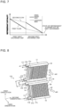
- FIG. 2 is a schematic view of the heat exchanger according to Embodiment 1 of the present invention as seen from a side.
- the solid arrows indicate flows of refrigerant, and the outline arrows indicate flows of air.
- the first heat exchange unit 3a satisfies 0 degree ⁇ ⁇ 1 ⁇ 90 degrees, where ⁇ 1 is the angle of the first heat exchange unit 3a with respect to the third orientation.
- the second heat exchange unit 3b satisfies 90 degrees ⁇ ⁇ 2 ⁇ 180 degrees, where ⁇ 2 is the angle of the second heat exchange unit 3b relative to the third orientation.
- ⁇ 2 is the angle of the second heat exchange unit 3b relative to the third orientation.
- the angle of the first heat exchange unit relative to the third orientation is equivalent to an angle formed between the third orientation and a direction of extension of the heat transfer pipes of the first heat exchange unit.
- refrigerant flows through the first heat exchange unit 3a first and then the second heat exchange unit 3b. Moreover, in passing through the heat exchanger, gas refrigerant or two-phase gas-liquid refrigerant flows out in liquefied form while exchanging heat with air blown from a fan. In so doing, refrigerant of the first heat transfer pipe group 21a on the windward side of the heat exchange unit 3a flows into the fourth heat transfer pipe group 21d on the leeward side of the second heat exchange unit 3b. Further, refrigerant of the second heat transfer pipe group 21b on the leeward side of the first heat exchange unit 3a flows into the third heat transfer pipe group 21c on the windward side of the second heat exchange unit 3b.
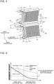
- FIG. 3 is a graph showing a relationship between air and refrigerant that pass through the heat exchanger according to Embodiment 1 of the present invention.
- FIG. 3 uses a line (a) to indicate changes in temperature of air in a case where the heat exchanger is used as a condenser.
- FIG. 3 uses a line (b) to indicate temperature in a case where the refrigerant is two-phase gas-liquid refrigerant.
- the horizontal axis represents refrigerant flow passages in the heat exchanger, and the vertical axis represents temperature.
- the first heat transfer pipe group 21a on the windward side and the second heat transfer pipe group 21b on the leeward side are constant in temperature of refrigerant in a case where the refrigerant is two-phase gas-liquid refrigerant.
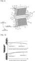
- FIG. 4 is a perspective view representing in detail flows of refrigerant during use of the heat exchanger according to Embodiment 1 of the present invention as a condenser.
- High-temperature and high-pressure gas refrigerant or two-phase gas-liquid refrigerant flows in through the upper inlet and outlet pipes 110 and 111 and reaches the first headers 10 and 11, respectively. Presuming that the flow of refrigerant having flowed into the first header 10 is a first flow and the flow of refrigerant having flowed into the first header 11 is a second flow, the following describes these flows.
- the refrigerant having flowed into the first header 10 flows in a positive direction of the second orientation through the first header 10 and flows into the first heat transfer pipe group 21a on the windward side in the first heat exchange unit 3a.
- Flows of refrigerant having passed through the first heat transfer pipe group 21a merge at the second header 12 into refrigerant that flows in a negative direction of the second orientation to flow out from the second header 12.
- the refrigerant having flowed out from the second header 12 flows in the positive direction of the second orientation into the second header 15 through the connecting pipe 112 first and then the connecting pipe 115.
- the refrigerant having flowed into the second header 15 flows into the fourth heat transfer pipe group 21d on the leeward side in the second heat exchange unit 3b. Flows of refrigerant having passed through the fourth heat transfer pipe group 21d merge at the third header 17 into refrigerant that flows in the negative direction of the second orientation to flow out of the lower inlet and outlet pipe 117.
- the refrigerant having flowed into the first header 11 flows in the negative direction of the second orientation through the first header 11 and flows into the second heat transfer pipe group 21b on the leeward side in the first heat exchange unit 3a.
- Flows of refrigerant having passed through the second heat transfer pipe group 21b merge at the second header 13 into refrigerant that flows in the negative direction of the second orientation to flow out from the second header 13.
- the refrigerant having flowed out from the second header 13 flows in the positive direction of the second orientation into the second header 14 through the connecting pipe 113 first and then the connecting pipe 114.
- the refrigerant having flowed into the second header 14 flows into the third heat transfer pipe group 21c on the windward side in the second heat exchange unit 3b. Flows of refrigerant having passed through the third heat transfer pipe group 21c merge at the third header 16 into refrigerant that flows in the negative direction of the second orientation to flow out of the lower inlet and outlet pipe 116.
- Embodiment 1 features of Embodiment 1 are divided into the following two features:
- Including the feature (1) causes the heat exchanger to, when functioning as a condenser, have no flow passage through which refrigerant flows in a direction opposite to the direction of gravitational force. This makes liquid refrigerant unable to defy gravity and thereby prevents it from staying in the intermediate header unit 18.
- the heat exchanger does not particularly include the feature (2), and is conventionally configured such that in the process of an upward or downward flow of refrigerant, refrigerant upstream and downstream sides do not swap windward and leeward sides with each other.
- FIG. 5 is a diagram showing flows of refrigerant in a case where the heat exchanger of the comparative example functions as a condenser.
- FIG. 6 is a graph showing an enthalpy state where first and second flows of refrigerant of the flows of refrigerant of FIG. 5 change as they proceed in flow directions.
- the heat exchanger of the comparative example shown in FIG. 5 has a flow passage configuration in which refrigerant upstream and downstream sides of each of the first and second flows do not swap windward and leeward sides with each other. That is, in this configuration, the second header 12 on the windward side and the windward second header 14 on the windward side communicate with each other through the intermediate header unit 180, and the second header 13 on the leeward side and the second header 15 on the leeward side communicate with each other through the intermediate header unit 180.
- the first flow is such that refrigerant having flowed into the first header 10 flows into the first heat transfer pipe group 21a on the windward side in the first heat exchange unit 3 a.
- Flows of refrigerant having passed through the first heat transfer pipe group 21a merge at the second header 12 into refrigerant that flows into the second header 14 through the connecting pie 112 first and then the connecting pipe 114.
- the refrigerant having flowed into the second header 14 flows into the third heat transfer pipe group 21c on the windward in the second heat exchange unit 3b.
- Flows of refrigerant having passed through the third heat transfer pipe group 21c merge at the third header 16 into a flow that flows out of the lower inlet and outlet pipe 116.
- the second flow is such that refrigerant having flowed into the first header 11 flows into the second heat transfer pipe group 21b on the leeward side in the first heat exchange unit 3a.
- Flows of refrigerant having passed through the second heat transfer pipe group 21b merge at the second header 13 into refrigerant that flows into the second header 15 through the connecting pipe 113 first and then the connecting pipe 115.
- the refrigerant having flowed into the second header 15 flows into the fourth heat transfer pipe group 21d on the leeward side in the second heat exchange unit 3b.
- Flows of refrigerant having passed through the fourth heat transfer pipe group 21d merge at the third header 17 into a flow that flows out of the lower inlet and outlet pipe 117.
- the first flow and the second flow differ from each other in terms of an enthalpy state of refrigerant flowing out of the heat exchanger, as shown in FIG. 6 .
- the first flow which continues to flow through the windward side, is smaller in refrigerant enthalpy than the second flow, which continues to flow through the leeward side.
- the first flow greatly differs in temperature from the air, so that there is a great decrease in refrigerant enthalpy in the first heat exchange unit 3a.
- the first flow comes close in temperature to the air in the single-phase gas refrigerant state. This makes the first flow hardly able to cause a decrease in refrigerant enthalpy in the second heat exchange unit 3b. This makes a portion of the first flow hardly able to function in heat exchange, as a result, leading to deterioration in efficiency of the heat exchanger.
- the second flow only slightly differs in temperature from the air by flowing through the leeward side, so that the enthalpy state of refrigerant having passed through the second heat exchange unit 3b is kept high. This causes the second flow to flow out of the heat exchanger without completely transferring to the air the amount of heat that the second flow has, leading as a result to insufficiency in the amount of heat that is given from the second flow of refrigerant to the air.
- one of the first and second flows continues to flow through the windward side, the other one of the first and second flows continues to flow through the leeward side.
- the heat exchanger of Embodiment 1 makes the first flow and the second flow capable of well-balanced heat exchange. A detailed description will be given below.
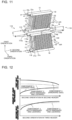
- FIG. 7 is a graph showing an enthalpy state where first and second flows of refrigerant in a case where the heat exchanger according to Embodiment 1 of the present invention functions as a condenser change as they proceed in flow directions.
- the first flow flows through the windward side in the first heat exchange unit 3a and flows through the leeward side in the second heat exchange unit 3b.
- the second flow flows through the leeward side in the first heat exchange unit 3a and flows through the windward side in the second heat exchange unit 3b.
- a comparison between the first flow and the second flow in the first heat exchange unit 3a shows that the first flow, which flows through the windward side, is greater in temperature difference between the refrigerant and the air and therefore more greatly decreases in refrigerant enthalpy than the second flow, which flows through the leeward side.
- a comparison between the first flow and the second flow in the second heat exchange unit 3b shows that the second flow, which flows through the windward side, is greater in temperature difference between the refrigerant and the air and therefore more greatly decreases in refrigerant enthalpy than the first flow, which flows through the leeward side.
- Embodiment 1 has features in a case where the heat exchanger functions as a condenser, the following describes flows of refrigerant in a case where the heat exchanger functions as an evaporator.
- FIG. 8 is a perspective view representing flows of refrigerant during use of the heat exchanger according to Embodiment 1 of the present invention as an evaporator.
- the heat exchanger functions as an evaporator
- two-phase gas-liquid refrigerant made up of a mixture of low-temperature and low-pressure gas refrigerant and liquid refrigerant flows in becomes liquefied by exchanging heat with air in the process of flowing through the heat exchanger, and flows out as liquid refrigerant.
- the refrigerant having flowed into the third header 16 flows into the third heat transfer pipe group 21c on the windward side in the second heat exchange unit 3b.
- Flows of refrigerant having passed through the third heat transfer pipe group 21c merge at the second header 14 into refrigerant that flows into the second header 13 through the connecting pipe 114 first and then the connecting pipe 113.
- the refrigerant having flowed into the second header 13 flows into the second heat transfer pipe group 21b on the leeward side in the first heat exchange unit 3a.
- Flows of refrigerant having passed through the second heat transfer pipe group 21b merge at the first header 11 into refrigerant that flows out of the upper inlet and outlet pipe 111.
- the refrigerant having flowed into the third header 17 flows into the fourth heat transfer pipe group 21d on the leeward side in the second heat exchange unit 3b.
- Flows of refrigerant having passed through the fourth heat transfer pipe group 21d merge at the second header 15 into refrigerant that flows into the second header 12 through the connecting pipe 115 first and then the connecting pipe 112.
- the refrigerant having flowed into the second header 12 flows into the first heat transfer pipe group 21a on the windward side in the first heat exchange unit 3a.
- Flows of refrigerant having passed through the first heat transfer pipe group 21a merge at the first header 10 into refrigerant that flows out of the upper inlet and outlet pipe 110.
- Liquid refrigerants are present in the second headers 12 and 13. Therefore, under the influence of gravity, flows of refrigerant that flow backward to the second headers 15 and 14 are generated in the second headers 12 and 13, respectively. However, subsequent flows of refrigerant that flow in from the second headers 15 and 14 are generated in the second headers 12 and 13, respectively. Therefore, the liquid refrigerants inside the second headers 12 and 13 are pushed out by the flows of refrigerant that flow in from the second headers 15 and 14, respectively. This causes the liquid refrigerants inside the second headers 12 and 13 to be sent to the first heat exchange unit 3a without staying in the second headers 12 and 13, respectively.
- Embodiment 1 is configured such that in a case where the heat exchanger functions as a condenser, refrigerant flows downward from an inlet to an outlet through the heat exchanger. This makes liquid refrigerant unable to defy gravity and thereby prevents it from staying in the heat exchanger. That is, the liquid refrigerant is discharged without staying in the heat exchanger. Further, since the liquid refrigerant does not stay in the heat exchanger, the liquid refrigerant can be inhibited from staying with refrigerating machine oil dissolved in the liquid refrigerant.
- Embodiment 1 which makes it possible to inhibit liquid refrigerant and refrigerating machine oil from staying, makes it possible to avoid excessive charging of refrigerant and refrigerating machine oil.
- Embodiment 1 there are two parallel flows of refrigerant, and each flow of refrigerant flows from the first heat exchange unit 3a to the second heat exchange unit 3b via the intermediate header unit 18.
- the intermediate header unit 18 is configured such that in a case where the heat exchanger functions as a condenser, at least a portion of refrigerant having flowed downward through the first heat transfer pipe group 21a and flowed out through the lower end of the first heat transfer pipe group 21a flows in through the upper end of the fourth heat transfer pipe group 21d and flows downward through the fourth heat transfer pipe group 21d.
- the intermediate header unit 18 is configured such that at least a portion of refrigerant having flowed downward through the second heat transfer pipe group 21b and flowed out through the lower end of the second heat transfer pipe group 21b flows in through the upper end of the third heat transfer pipe group 21c and flows downward through the third heat transfer pipe group 21c.
- the heat exchanger has a flow passage configuration in which refrigerant upstream and downstream sides of each of the first and second flows, which flow through heat transfer pipe groups arranged in two rows, swap windward and leeward sides with each other.
- the heat exchanger of Embodiment 1 includes the first headers 10 and 11, the intermediate header unit 18, and the third headers 16 and 17.
- the intermediate header unit 18 includes the communicating unit 118, through which the upper second headers 12 and 13 communicate with the lower second headers 14 and 15.
- flow passages can be made up of the plurality of headers and the communicating unit 118.
- the communicating unit 118 has the first communicating pipe 118a and the second communicating pipe 118b. One end of the first communicating pipe 118a is connected to the second header 12 at the lower end of the first heat transfer pipe group 21a, and the other end of the first communicating pipe 118a is connected to the second header 15 at the upper end of the fourth heat transfer pipe group.
- One end of the second communicating pipe 118b is connected to the second header 13 at the lower end of the second heat transfer pipe group 21b, and the other end of the second communicating pipe 118b is connected to the second header 14 at the upper end of the third heat transfer pipe group 21c.
- Both the first communicating pipe 118a and the second communicating pipe 118b are connected to the same side, which is either the positive side or the negative side of the second orientation.
- both the first communicating pipe 118a and the second communicating pipe 118b are connected to the negative side. This makes it possible to make flow passages between the upper second headers 12 and 13 and the lower second headers 14 and 15 shorter than in a case where the first communicating pipe 118a and the second communicating pipe 118b are connected separately to the positive and negative sides of the second orientation.
- the upper inlet and outlet pipes 110 and 111 and the lower inlet and outlet pipes 116 and 117 are connected to the negative side of the second orientation in the same way as the first communicating pipe 118a and the second communicating pipe 118b.
- This causes the first headers 10 and 11 connected to the upper side of the first heat exchange unit 3a and the second headers 12 and 13 connected to the lower side of the first heat exchange unit 3a to be opposite in refrigerant flow direction to each other.
- this causes the second headers 14 and 15 connected to the upper side of the second heat exchange unit 3b and the third headers 16 and 17 connected to the lower side of the second heat exchange unit 3b to be opposite in refrigerant flow direction to each other.
- Embodiment 2 differs from Embodiment 1 in respect of a flow direction of refrigerant through the intermediate header unit 18. The following describes Embodiment 2 with a focus on differences in configuration from Embodiment 1.
- FIG. 9 is a front perspective view showing a heat exchanger according to Embodiment 2 of the present invention.
- FIG. 9 shows flows of refrigerant in a case where the heat exchanger functions as an evaporator.
- the heat exchanger of Embodiment 2 is configured such that the connecting pipes 112 to 115, which are connected to the negative side of the second orientation in Embodiment 1, of the intermediate header unit 18 are connected to the positive side of the second orientation. That is, the heat exchanger of Embodiment 2 is configured such that the "connecting pipes 112 to 115 of the intermediate header unit 18" and the "upper inlet and outlet pipes 110 and 111 and the lower inlet and outlet pipes 116 and 117" are connected to opposite sides of the corresponding headers in the second orientation.
- This configuration causes the first headers 10 and 11 connected to the upper side of the first heat exchange unit 3 a and the second headers 12 and 13 connected to the lower side of the first heat exchange unit 3a to be identical in refrigerant flow direction to each other. Further, this configuration causes the second headers 14 and 15 connected to the upper side of the second heat exchange unit 3b and the third headers 16 and 17 connected to the lower side of the second heat exchange unit 3b to be identical in refrigerant flow direction to each other.
- two-phase gas-liquid refrigerant made up of a mixture of low-temperature and low-pressure gas refrigerant and liquid refrigerant flows in through the lower inlet and outlet pipes 116 and 117 connected to the positive side of the second orientation and reaches the third headers 16 and 17.
- the refrigerant having flowed into the third header 16 flows in the positive direction of the second orientation through the third header 16 and flows into the third heat transfer pipe group 21c on the windward side in the second heat exchange unit 3b.
- Flows of refrigerant having passed through the third heat transfer pipe group 21c merge at the second header 14 into refrigerant that flows in the positive direction of the second orientation to flow out from the second header 14.
- the refrigerant having flowed out from the second header 14 flows in the negative direction of the second orientation into the second header 13 through the connecting pipe 114 first and then the connecting pipe 113.
- the refrigerant having flowed into the second header 13 flows into the second heat transfer pipe group 21b on the leeward side in the first heat exchange unit 3a.
- Flows of refrigerant having passed through the second heat transfer pipe group 21b merge at the first header 11 into refrigerant that flows in the negative direction of the second orientation to form a flow that flows out of the upper inlet and outlet pipe 111.
- the refrigerant having flowed into the third header 17 flows in the positive direction through the third header 17 and flows into the fourth heat transfer pipe group 21d on the leeward side in the second heat exchange unit 3b.
- Flows of refrigerant having passed through the fourth heat transfer pipe group 21d merge at the second header 15 into refrigerant that flows in the positive direction of the second orientation to flow out from the second header 15.
- the refrigerant having flowed out from the second header 15 flows in the negative direction of the second orientation into the second header 12 through the connecting pipe 115 first and then the connecting pipe 112.
- the refrigerant having flowed into the second header 12 flows into the first heat transfer pipe group 21a on the windward side in the first heat exchange unit 3a. Flows of refrigerant having passed through the first heat transfer pipe group 21a merge at the first header 10 into refrigerant that flows in the negative direction of the second orientation to form a flow that flows out of the upper inlet and outlet pipe 110.
- FIG. 10 is a graph showing a distribution of liquid refrigerant within the heat exchanger according to Embodiment 2 of the present invention in a case where the heat exchanger functions as an evaporator.
- FIG. 10 also shows a distribution of liquid refrigerant in Embodiment 1.
- the horizontal axis represents the positions of the second headers and the third headers in the second orientation
- the vertical axis represents the amount of liquid refrigerant.
- the headers on the upper side of the second heat exchange unit 3b and the headers on the lower side of the second heat exchange unit 3b are opposite in refrigerant flow direction to each other. Therefore, much of the gas refrigerant, which has a great pressure loss of refrigerant, is distributed in the negative direction of the second orientation of the third headers, so that flow passages are formed that lead by the most direct way to the connecting pipes 114 and 115 through the heat transfer pipe groups on the negative side of the second orientation in the second heat exchange unit 3b. This generates a flow that reduces the pressure loss of refrigerant.
- the headers on the upper side of the second heat exchange unit 3b and the headers on the lower side of the second heat exchange unit 3b are identical in refrigerant flow direction to each other. This ensures uniformity in length of flow passages that lead into the third headers through the lower inlet and outlet pipes 116 and 117, pass through heat transfer pipes, and then reach the connecting pipes 114 and 115, respectively, no matter which heat transfer pipes the flow passages pass through.
- the headers on the upper side of the second heat exchange unit 3b and the headers on the lower side of the second heat exchange unit 3b are identical in refrigerant flow direction to each other. This makes it easy for the gas refrigerant and the liquid refrigerant to be uniformly distributed.
- Embodiment 2 brings about the same effects as Embodiment 1 and brings about the following effects. That is, Embodiment 2 is configured such that the "connecting pipes 112 to 115 of the intermediate header unit 18" and the "upper inlet and outlet pipes 110 and 111 and the lower inlet and outlet pipes 116 and 117" are connected to opposite sides of the corresponding headers in the second orientation.
- This configuration causes the first headers 10 and 11 connected to the upper side of the first heat exchange unit 3a and the second headers 12 and 13 connected to the lower side of the first heat exchange unit 3a to be identical in refrigerant flow direction to each other. Further, this configuration causes the second headers 14 and 15 connected to the upper side of the second heat exchange unit 3b and the third headers 16 and 17 connected to the lower side of the second heat exchange unit 3b to be identical in refrigerant flow direction to each other.
- Embodiment 2 is configured such that in a case where the heat exchanger functions as a condenser, refrigerant that liquefies flows downward through a flow passage. This prevents the liquid refrigerant and refrigerating machine oil dissolved in the liquid refrigerant from staying in the heat exchanger, making it possible to avoid excessive charging of refrigerant and refrigerating machine oil.
- Embodiment 3 differs from Embodiment 1 in respect of a configuration of the intermediate header unit 18. The following describes Embodiment 3 with a focus putting on differences in configuration from Embodiment 1.
- FIG. 11 is a front perspective view showing a heat exchanger according to Embodiment 3 of the present invention.
- FIG. 11 shows flows of refrigerant in a case where the heat exchanger functions as an evaporator.
- the heat exchanger of Embodiment 3 is configured such that the interiors of the second headers 14 and 15 of the intermediate header unit 18 are divided by dividers 140 and 150 at the center of the second orientation, respectively. Such division leads to the formation of a negative-side header 14a and a positive-side header 14b in the second header 14 and the formation of a negative-side header 15a and a positive-side header 15b in the second header 15.
- the intermediate header unit 18 has a communicating unit 118 through which the upper second headers 12 and 13 communicate with the lower second headers 14 and 15.
- the communicating unit 118 has a first communicating pipe 118a and a second communicating pipe 118b. One end of the second communicating pipe 118b is connected to the second header 12, and the other end of the second communicating pipe 118b is bifurcated to be connected to the positive-side headers 14b and 15b.
- the second communicating pipe 118b is made up of a connecting pipe 112, a U bend 101b, a bifurcated pipe 25, a connecting pipe 114b, and a connecting pipe 115b.
- One end of the first communicating pipe 118a is connected to the second header 13, and the other end of the first communicating pipe 118a is bifurcated to be connected to the negative-side headers 14a and 15a.
- the first communicating pipe 118a is made up of a connecting pipe 112, a U bend 101b, a bifurcated pipe 25, a connecting pipe 114a, and a connecting pipe 115a.
- two-phase gas-liquid refrigerant made up of a mixture of low-temperature and low-pressure gas refrigerant and liquid refrigerant flows in through the lower inlet and outlet pipes 116 and 117 disposed on the negative side of the second orientation and reaches the third headers 16 and 17, respectively.
- the refrigerant having flowed into the third header 16 flows into the third heat transfer pipe group 21c on the windward side in the second heat exchange unit 3b. Flows of refrigerant having passed through the third heat transfer pipe group 21c flow into the two divisions, namely the negative-side and positive-side headers 14a and 14b, of the second header 14.
- the refrigerant having flowed into the third header 17 flows into the fourth heat transfer pipe group 21d on the leeward side in the second heat exchange unit 3b.
- Flows of refrigerant having passed through the fourth heat transfer pipe group 21d flow into the two divisions, namely the negative-side and positive-side headers 15a and 15b, of the second header 15.
- the refrigerant of the positive-side header 14b and the refrigerant of the positive-side header 15b merge after having flowed out from the connecting pipes 114b and 115b, respectively. Then, the merged refrigerant flows into the connecting pipe 112 and then flows into the second header 12. The refrigerant having flowed into the second header 12 flows into the first heat transfer pipe group 21a. Flows of refrigerant having passed through the first heat transfer pipe group 21a merge at the first header 10 into a flow that flows out from the upper inlet and outlet pipe 110.
- FIG. 12 is a graph showing a distribution of liquid refrigerant within the heat exchanger according to Embodiment 3 of the present invention in a case where the heat exchanger functions as an evaporator.
- FIG. 12 also shows a distribution of liquid refrigerant in Embodiment 2.
- the horizontal axis represents the positions of the second headers and the third headers in the second orientation
- the vertical axis represents the amount of liquid refrigerant.
- the interiors of the second headers 14 and 15 are divided by the dividers 140 and 150 into two parts at the center of the second orientation in the aforementioned manner. Therefore, a large amount of liquid refrigerant is distributed in the positive-side headers 14b and 15b, which are located on the positive side of the second orientation, and a large amount of gas refrigerant is distributed in the negative-side headers 14a and 15a, which are located on the negative side of the second orientation.
- the liquid refrigerant of the positive-side headers 14b and 15b flows into the first heat transfer pipe group 21a after having been supplied to the second header 12 on the windward side of the first heat exchange unit 3a through the connecting pipes 114b, 115b, and 112.
- a large amount of liquid refrigerant flows into the first heat transfer pipe group 21a of the windward side.
- the large amount of liquid refrigerant having flowed into the first heat transfer pipe group 21a on the windward side greatly differs in temperature from air and therefore can sufficiently exchange heat with air in the first heat transfer pipe group 21a.
- the refrigerant in the negative-side headers 14a and 15a in which a large amount of gas refrigerant is distributed with a small amount of liquid refrigerant, flows into the second heat transfer pipe group 21b after having been supplied to the second header 13 on the leeward side of the first heat exchange unit 3a through the connecting pipes 114a, 115a, and 113.
- the small amount of liquid refrigerant flowing into the second heat transfer pipe group 21b only slightly differs in temperature from air and therefore does not completely evaporate in the middle of the second heat transfer pipe group 21b. This makes it possible to carry out efficient heat exchange.
- liquid refrigerant flows in the negative direction of the second orientation into the second header 12, much of the liquid refrigerant tends to be distributed in the negative direction of the second orientation within the second header 12. Since the refrigerant flows into the first heat transfer pipe group 21a with this distribution kept, more of the liquid refrigerant is distributed to heat transfer pipes of the first heat transfer pipe group 21a located on the negative side than to heat transfer pipes of the first heat transfer pipe group 21a located on the positive side.
- air flowing into a positive-side area of the first heat exchange unit 3a in the second orientation undergoes a small temperature change by exchanging heat with a smaller amount of liquid refrigerant in the first heat transfer pipe group 21a on the windward side than on the negative side of the second orientation.
- air flowing into a negative-side area of the first heat exchange unit 3a in the second orientation undergoes a great temperature change by exchanging heat with a larger amount of liquid refrigerant in the first heat transfer pipe group 21a on the windward side than on the positive side of the second orientation.
- air having flowed into the second heat transfer pipe group 21b on the leeward side exchanges heat with a "smaller amount of liquid refrigerant" than on the negative side of the second orientation.
- the "small amount of liquid refrigerant" in the second heat transfer pipe group 21b can carry out necessary heat exchange on the leeward side of the first heat exchange unit 3a, even with a small difference in temperature between the air and the liquid refrigerant.
- Embodiment 3 brings about the same effects as Embodiment 1 and brings about the following effects.
- the interiors of the second headers 14 and 15 are divided at the center of the second orientation, whereby the positive-side and negative-side headers 14b and 14a and the positive-side and negative-side headers 15b and 15a are formed.
- the communicating unit 118 has the first communicating pipe 118a and the second communicating pipe 118b.
- One end of the first communicating pipe 118a is connected to the second header 12, and the other end of the first communicating pipe 118a is bifurcated to be connected to the positive-side headers 14b and 15b.
- One end of the second communicating pipe 118b is connected to the second header 13, and the other end of the second communicating pipe 118b is bifurcated to be connected to the negative-side headers 14a and 15a.
- This configuration makes it possible to achieve a well-balanced distribution of the liquid refrigerant to the positive-side and negative-side areas in the first heat exchange unit 3a in the second orientation, making it possible to carry out efficient heat exchange.
- Embodiment 3 is configured such that in a case where the heat exchanger functions as an evaporator, a large amount of liquid refrigerant flows through the windward side in the heat exchanger, and a small amount of liquid refrigerant flows through the leeward side in the heat exchanger. This makes it possible to distribute refrigerant according to a difference in temperature between air and liquid refrigerant.
- Embodiment 3 is configured such that in a case where the heat exchanger is used as a condenser, refrigerant that liquefies flows downward through a flow passage. This prevents the liquid refrigerant and refrigerating machine oil dissolved in the liquid refrigerant from staying in the heat exchanger, making it possible to avoid excessive charging of refrigerant and refrigerating machine oil.
- Embodiment 4 relates to a configuration in which the heat exchanger is divided into a plurality of heat exchangers. Further, Embodiment 4 describes a case where the heat exchanger functions as a condenser.
- FIG. 13 is a perspective view showing flows of refrigerant in a heat exchanger of Pattern 1 according to Embodiment 4 of the present invention.
- the heat exchanger of Embodiment 4 is divided into two parts in the second orientation, whereby a positive-side heat exchanger 300b and a negative-side heat exchanger 300a are formed.
- the positive-side heat exchanger 300b and the negative-side heat exchanger 300a are connected in series through a connecting unit 320.
- the heat exchanger of Embodiment 4 includes this configuration throughout Patterns 2 to 4, which will be described below, as well as Pattern 1.
- the heat exchanger of Pattern 1 has a configuration in which the heat exchanger of Embodiment 2 shown in FIG. 9 , that is, a heat exchanger in which upper and lower headers of a heat exchange unit are identical in refrigerant flow direction to each other, is divided into two heat exchangers in the second orientation. Further, the heat exchanger of Pattern 1 has a configuration in which two flows of refrigerant flow at the connection between the positive-side heat exchanger 300b and the negative-side heat exchanger 300a.
- components of the negative-side heat exchanger 300a on the refrigerant downstream side are given the same signs as those used in FIG. 2 .
- the positive-side heat exchanger 300a on the refrigerant upstream side is given new signs as appropriate.
- the positive-side heat exchanger 300b on the refrigerant upstream side has a first heat exchange unit 3c located upward in the direction of gravitational force and a second heat exchange unit 3d located downward in the direction of gravitational force.
- the first heat exchange unit 3c extends in a direction at the angle ⁇ 1.
- the second heat exchange unit 3b the second heat exchange unit 3d extends in a direction at the angle ⁇ 2.
- High-temperature and high-pressure gas refrigerant or two-phase gas-liquid refrigerant flows in through inlet and outlet pipes 310 and 311 and reaches first headers 30 and 31, respectively.
- the following assumes that the flow of refrigerant having flowed into the first header 30 is a first flow and the flow of refrigerant having flowed into the first header 31 is a second flow.
- the refrigerant having flowed into the first header 30 flows into the first heat transfer pipe group 21a on the windward side in the first heat exchange unit 3c.
- Flows of refrigerant having passed through the first heat transfer pipe group 21a merge at a second header 32 into refrigerant that flows into a second header 35 through a connecting pipe 312 first and then a connecting pipe 315.
- the refrigerant having flowed into the second header 35 flows into the fourth heat transfer pipe group 21d on the leeward side in the second heat exchange unit 3d.
- Flows of refrigerant having passed through the fourth heat transfer pipe group 21d merge at a third header 37 into refrigerant that reaches the first header 11 through the upper inlet and outlet pipe 111 from a connecting pipe 317.
- the refrigerant having flowed into the first header 11 forms a flow that flows out via the second heat transfer pipe group 21b on the leeward side in the first heat exchange unit 3a, the second header 13, the connecting pipe 113, the connecting pipe 114, the second header 14, the third heat transfer pipe group 21c on the windward side in the second heat exchange unit 3b, the third header 16, and the lower inlet and outlet pipe 116.
- the refrigerant having flowed into the first header 31 flows into the second heat transfer pipe group 21b on the leeward side in the first heat exchange unit 3c.
- Flows of refrigerant having passed through the second heat transfer pipe group 21b merge at a second header 33 into refrigerant that flows into a second header 34 through a connecting pipe 313 first and then a connecting pipe 314.
- the refrigerant having flowed into the second header 34 flows into the third heat transfer pipe group 21c on the windward side in the second heat exchange unit 3d.
- Flows of refrigerant having passed through the third heat transfer pipe group 21c merge at a third header 36 into refrigerant that reaches the first header 10 through the upper inlet and outlet pipe 110 from a connecting pipe 316.
- the refrigerant having flowed into the first header 10 forms a flow that flows out via the first heat transfer pipe group 21a on the windward side in the first heat exchange unit 3a, the second header 12, the connecting pipe 112, the connecting pipe 115, the second header 15, the fourth heat transfer pipe group 21d on the leeward side in the second heat exchange unit 3b, the third header 17, and the lower inlet and outlet pipe 117.
- Embodiment 1 or 3 may be used to configure a heat exchanger divided in the second orientation, although FIG. 13 is illustrated by using Embodiment 2 as an example.
- Embodiments 1 to 3 may be combined to configure a heat exchanger divided in the second orientation.
- FIG. 14 is a perspective view showing flows of refrigerant in a heat exchanger of Pattern 2 according to Embodiment 4 of the present invention.
- the heat exchanger of Pattern 2 has a configuration in which the heat exchanger of Embodiment 1 shown in FIG. 4 is divided into two serially-connected parts in the second orientation and two flows of refrigerant converge into one flow of refrigerant at the serial connection. Further, the heat exchanger of Pattern 2 applies Embodiment 1 to the first heat exchange unit 3c and applies Embodiment 2 to the second heat exchange unit 3d. That is, upper and lower headers of the first heat exchange unit 3c are opposite in refrigerant flow direction to each other. Further, upper and lower headers of the second heat exchange unit 3d are opposite in refrigerant flow direction to each other.
- the positive-side heat exchanger 300b is configured such that the second headers 32 and 33 and the second headers 34 and 35 are connected to each other so that refrigerant that flowed on the windward side in the first heat exchange unit 3c flows through the leeward side in the second heat exchange unit 3d and refrigerant that flowed on the leeward side in the first heat exchange unit 3c flows through the windward side in the second heat exchange unit 3d.
- the negative-side heat exchanger 300a applies a configuration in which in the process of an upward or downward flow of refrigerant, a flow that passes through the windward side and a flow that passes through the leeward side do not interchange.
- Flows of refrigerant in the positive-side heat exchanger 300b are the same as flows of refrigerant in the positive-side heat exchanger 300b of FIG. 13 except that the direction of inflow of refrigerant into the first headers 30 and 31 is opposite to the direction of inflow of refrigerant into the first headers 30 and 31 of FIG. 13 .
- flows of refrigerant having flowed out from the connecting pipes 316 and 317 of the positive-side heat exchanger 300b merge at a bifurcated pipe 25 into refrigerant that reaches a third header 47 of the negative-side heat exchanger 300a.
- the refrigerant having passed through the third header 47 flows out of an inlet and outlet pipe 416 through the leeward side of the second heat exchange unit 3b, a second header 45, a second header 43, the leeward side of the first heat exchange unit 3a, a first header 41, a connecting pipe 411, a connecting pipe 410, a first header 40, the windward side of the first heat exchange unit 3a, the windward side of the second heat exchange unit 3b, and a third header 46.
- the positive-side heat exchanger 300b which is situated upstream of a refrigerant flow passage, is twice or more as large in capacity as the negative-side heat exchanger 300a, which is situated downstream of the refrigerant flow passage, so that the refrigerant flows into the negative-side heat exchanger 300a in a single-phase liquid state.
- the negative-side heat exchanger 300a is used for the purpose of providing subcooling for single-phase liquid refrigerant.
- FIG. 15 is a diagram showing a modification of the heat exchanger of FIG. 14 .
- a header 51 may be used instead of the third headers 36 and 37 of FIG. 14 .
- a header 61 may be used instead of the first headers 40 and 41 of FIG. 14 .
- a connecting pipe 510 may be used instead of the connecting pipes 316 and 317 of FIG. 14 and the bifurcated pipe 25 of FIG. 14 .
- the headers 51 and 61 are configured as below as shown in FIGS. 16 and 17 , respectively.
- FIG. 16 is a block diagram of the header 51 of FIG. 15 .
- FIG. 17 is a block diagram of the header 61 of FIG. 15 .
- the header 51 has a header plate 51a having formed therein a plurality of insertion holes 51aa into which flat heat transfer pipes are inserted, a frame plate 51b, and a header cover 51c.
- the header 51 functions to cause flows of refrigerant having flowed out from a windward-side heat transfer pipe group of the second heat exchange unit 3d and a leeward-side heat transfer pipe group of the second heat exchange unit 3d to merge into refrigerant that flows to the connecting pipe 510.
- the header 61 has a header plate 61a having formed therein a plurality of insertion holes 61aa into which flat heat transfer pipes are inserted, a drift prevention plate 61b, and a header cover 61c.
- the header 61 functions to cause refrigerant having passed through the leeward-side heat transfer pipe group of the first heat exchange unit 3a to flow to the windward-side heat transfer pipe group of the first heat exchange unit 3a.
- the third header 47 is filled with liquid refrigerant without affecting the state of the refrigerant in the third header 47 no matter whether an upward flow or a downward flow is generated in a flow passage situated downstream of the third header 47 along the refrigerant flow.
- a heat transfer pipe group of the negative-side heat exchanger 300a is filled with liquid refrigerant, too. That is, in a case where single-phase liquid refrigerant flows into the negative-side heat exchanger 300a, no such inconvenience occurs that liquid refrigerant stays without flowing, even if an upward flow is generated downstream of the third header 47 along the refrigerant flow. Therefore, it can be said that a configuration that does not require an excessive amount of refrigerant can be achieved by applying the configurations of Embodiments 1 to 3 to the positive-side heat exchanger 300b.
- FIG. 18 is a perspective view showing flows of refrigerant in a heat exchanger of Pattern 3 according to Embodiment 4 of the present invention.
- the heat exchanger of Pattern 3 is configured such that the first heat exchange unit 3a of Embodiment 1 shown in FIG. 1 is elongated in the second orientation and divided into two parts in the second orientation, whereby a first heat exchange unit 3a, a first heat exchange unit 3c, and a second heat exchange unit 3b are formed. Further, the heat exchanger of Pattern 3 has a second heat exchange unit 3d in which refrigerant forms an upward flow in a case where the heat exchanger functions as a condenser as in the case of a conventional heat exchanger. Thus, the heat exchanger of Pattern 3 is a combination of a configuration in which the heat exchanger of Embodiment 1 is divided and a related-art heat exchanger.
- FIG. 19 is a diagram showing a modification of the heat exchanger of FIG. 18 .
- the second heat exchange unit 3d of FIG. 18 described above is configured such that refrigerant forms parallel flows on the windward side and the leeward side.
- a conventional heat exchanger configured such that refrigerant forms a counterflow that flows from the windward side to the leeward side is used as the second heat exchange unit 3d.
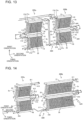
- FIG. 20 is a perspective view showing flows of refrigerant in a heat exchanger of Pattern 4 according to Embodiment 4 of the present invention.
- refrigerant having flowed through the first heat transfer pipe groups 21a on the windward sides of the first heat exchange units 3a and 3c flows to the fourth heat transfer pipe groups 21d on the leeward sides of the second heat exchange units 3b and 3d. That is, in this configuration, refrigerant upstream and downstream sides have swapped windward and leeward sides with each other. However, on the leeward sides of the first heat exchange units 3a and 3c, refrigerant having flowed through the second heat transfer pipe groups 21b flow to the fourth heat transfer groups 21d on the leeward sides of the second heat exchange units 3b and 3d.
- refrigerant upstream and downstream sides have not swapped windward and leeward sides with each other.
- refrigerant upstream and downstream sides of at least either refrigerant flowing into the heat exchanger through an upper inlet and outlet pipe 110a or refrigerant flowing into the heat exchanger through an upper inlet and outlet pipe 110b have swapped windward and leeward sides with each other. This configuration makes it possible to bring about improvement in heat exchange performance by ensuring uniform heat exchange balance.
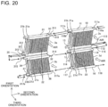
- FIG. 21 is a diagram showing a modification of the heat exchanger of FIG. 20 .
- refrigerant having flowed out from the second headers 12 and 13 and refrigerant having flowed out from the second headers 32 and 33 flow in parallel into the leeward side of the second heat exchange unit 3b and the leeward side of heat exchange unit 3d.
- refrigerant having flowed out from the second headers 12 and 13 flows into the second headers 32 and 33. Then, flows of refrigerant having flowed out from the second headers 32 and 33 merge into refrigerant that flows into the second header 35.
- the refrigerant having flowed into the second header 35 is divided into refrigerant that flows toward the second header 15 and refrigerant that flows toward the fourth heat transfer pipe group 21d on the leeward side of the second heat exchange unit 3b.
- the refrigerant having flowed toward the second header 15 passes through the third header 17 after having passed through the leeward side of the second heat exchange unit 3d, and then merges at the third header 37 with the refrigerant having passed through the fourth heat transfer pipe group 21d directly from the second header 35.
- the flow of refrigerant having passed through the third header 37 passes through the windward side of the second heat exchange unit 3b first and then the windward side of the heat exchange unit 3d.
- an upward flow of refrigerant is generated in a part of each of the configurations of FIGS. 18 to 21 .
- a flow passage of refrigerant situated downstream of a part where an upward flow is generated is filled with refrigerant assuming a liquid refrigerant state.
- the second heat exchange units 3d of FIGS. 18 and 19 and the windward sides of the second heat exchange units 3b and 3d of FIGS. 20 and 21 are filled with refrigerant flowing therethrough in a liquid refrigerant state.
- the amount of refrigerant that stays does not depend on the flow direction of refrigerant such as an upward flow or a downward flow.
- a configuration that does not require an excessive amount of refrigerant can be achieved by applying the configurations of Embodiments 1 to 3 to the first heat exchange unit 3a, the first heat exchange unit 3c, and the second heat exchange unit 3b. Further, it can be said that a configuration that does not require an excessive amount of refrigerant can be achieved by applying the configurations of Embodiments 1 to 3 to the first heat exchange units 3a, the first heat exchange units 3c, and the leeward sides of the second heat exchange units 3b and 3d of FIGS. 20 and 21 .
- Embodiment 4 makes it possible to improve heat exchanger performance by applying a configuration in which the configurations of Embodiments 1 to 3 are applied to one or both of the two heat exchangers. Further, in the process of liquefaction of single-phase gas or two-phase liquid-gas refrigerant, the formation of a flow passage that extends downward in a vertical direction prevents liquid refrigerant and refrigerating machine oil dissolved in the liquid refrigerant from staying in the heat exchanger. This makes it possible to reduce excessive charging of refrigerant and refrigerating machine oil.
- FIG. 22 is a schematic view of a configuration of pipes through which headers are connected to each other.
- the headers are connected to each other using U bends 101a and 101b.
- the configuration of FIG. 22 is applied to the connections between the second headers of FIGS. 4 , 5 , 7 , 9 , and 13 to 15 in particular.
- FIG. 23 is a schematic view of another configuration of pipes through which headers are connected to each other.
- FIG. 23 the headers are connected to each other using the U bends 101a and 101b and bifurcated pipes 25a and 25b.
- the configuration of FIG. 23 is applied to the connections between the second headers of FIGS. 11 , 20 , and 21 in particular.
- FIG. 24 is a schematic view of a configuration of pipes at places where refrigerant flows into and out of the heat exchanger.
- the configuration of pipes of FIG. 24 is applied to Embodiment 1 shown in FIG. 4 , although it is applied to all of Embodiments 1 to 4.
- Embodiments 1 to 4 there are two places in the heat exchange through which refrigerant flows in, and there are two places in the heat exchanger through which refrigerant flows out.
- a bifurcated pipe 25 is used at the places through which refrigerant flows in, and a bifurcated pipe 25 is used at the places through which refrigerant flows out.
- Embodiment 5 relates to a refrigeration cycle device including the heat exchanger of any of Embodiments 1 to 4.
- An air-conditioning device is described here as an example of the refrigeration cycle device.
- FIG. 25 is a block diagram of an air-conditioning device according to Embodiment 5 of the present invention.
- the solid arrows indicate a flow of refrigerant during cooling
- the dotted arrows indicate a flow of refrigerant during heating.
- the air-conditioning device has a compressor 1, a four-way valve 2, an outdoor heat exchanger 3, an expansion valve 4, and an indoor heat exchanger 5, and these components are connected through pipes to form a refrigerant circuit through which refrigerant circulates.
- the refrigerant circuit has refrigerating machine oil mixed therein to reduce deterioration of compression efficiency and deterioration of durability life due to wear in the compressor 1, and a portion of the refrigerating machine oil circulates through the refrigerant circuit together with the refrigerant.
- the air-conditioning device further includes a fan 7 configured to blow air to the outdoor heat exchanger 3 and a fan 6 configured to blow air to the indoor heat exchanger 5.
- the heat exchangers of Embodiments 1 to 4 may be applied to the outdoor heat exchanger 3 or may be applied to the indoor heat exchanger 5.
- high-temperature and high-pressure gas refrigerant compressed by the compressor 1 passes through the four-way valve 2 and reaches a point A. After having passed through the point A, the gas refrigerant flows into the outdoor heat exchanger 3.
- the outdoor heat exchanger 3 functions as a condenser. The gas refrigerant having flowed into the outdoor heat exchanger 3 is cooled by air blown by the fan 7 and reaches a point B in a liquefied state.
- the liquid refrigerant thus liquefied passes through the expansion valve 4 and thereby turns into two-phase refrigerant made up of a mixture of low-temperature and low-pressure gas refrigerant and liquid refrigerant, and the two-phase refrigerant reaches a point C.
- the two-phase refrigerant having passed through the point C flows into the indoor heat exchanger 5.
- the indoor heat exchanger 5 functions as an evaporator.
- the two-phase refrigerant having flowed into the indoor heat exchanger 5 is heated by air blown by the fan 6 and reaches a point D in a gasified state.
- the gas refrigerant having passed through the point D returns to the compressor 1 after having passed through the four-way valve 2. Through this cycle, the cooling operation of cooling indoor air is performed.
- the flows of refrigerant through the four-way valve 2 are interchanged so that the aforementioned flow is inverted. That is, the high-temperature and high-pressure gas refrigerant compressed by the compressor 1 flows to the point D after having passed through the four-way valve 2, and the refrigerant having passed through the indoor heat exchanger 5, the expansion valve 4, and the outdoor heat exchanger 3 reaches the point A and is taken by the four-way valve 2 into a flow passage to return to the compressor 1. Through this cycle, the heating operation of heating indoor air is performed.
- Example configurations of fans and examples of the placement of a fan and a heat exchanger are described with reference to FIGS. 26 to 31 .
- FIG. 26 is a schematic view showing a relationship between a heat exchanger and a turbo fan in the air-conditioning device according to Embodiment 5 of the present invention.
- the turbo fan 70 is disposed on the windward side of the heat exchanger.
- FIG. 27 is a schematic view showing a relationship between the heat exchanger and a sirocco fan in the air-conditioning device according to Embodiment 5 of the present invention.
- the sirocco fan 71 is disposed on the windward side of the heat exchanger.
- FIG. 28 is a schematic view showing a relationship between the heat exchanger and the sirocco fan in the air-conditioning device according to Embodiment 5 of the present invention.
- the sirocco fan 71 is disposed on the leeward side of the heat exchanger.
- FIG. 29 is a schematic view showing a relationship between the heat exchanger and a line flow fan in the air-conditioning device according to Embodiment 5 of the present invention.
- the line flow fan 72 is disposed on the leeward side of the heat exchanger.
- FIG. 30 is a schematic view showing a positional relationship between the heat exchanger and a propeller fan in the air-conditioning device according to Embodiment 5 of the present invention.
- the propeller fan 73 is disposed on the leeward side of the heat exchanger.
- FIG. 31 is a schematic view showing a positional relationship between the heat exchanger and the propeller fan in the air-conditioning device according to Embodiment 5 of the present invention.
- the propeller fan 73 is disposed on the leeward side of the heat exchanger.
- FIG. 31 differs from FIG. 30 in that while the heat exchanger and the propeller fan 73 are placed in FIG. 30 so that air flows in a linear fashion, the heat exchanger and the propeller fan 73 are placed in FIG. 31 so that air flows in a curved fashion.
- a fan and a heat exchanger need only be placed so that air from the fan passes through the heat exchanger.
- a heat exchanger according to an Embodiment of the present invention is applicable, for example, to a heat pump device, a hot-water supply device, or a refrigeration device as well as the aforementioned air-conditioning device.
Landscapes
- Engineering & Computer Science (AREA)
- Mechanical Engineering (AREA)
- General Engineering & Computer Science (AREA)
- Physics & Mathematics (AREA)
- Thermal Sciences (AREA)
- Chemical & Material Sciences (AREA)
- Combustion & Propulsion (AREA)
- Heat-Exchange Devices With Radiators And Conduit Assemblies (AREA)
- Compression-Type Refrigeration Machines With Reversible Cycles (AREA)
Claims (13)
- Échangeur de chaleur comprenant une première unité d'échange de chaleur (3a) et une seconde unité d'échange de chaleur (3b) disposée l'une au-dessus de l'autre,- la première unité d'échange de chaleur (3a) et la seconde unité d'échange de chaleur (3b) ayant chacune un groupe de tubes de transfert de chaleur configurés de telle sorte qu'une pluralité de tubes de transfert de chaleur, s'étendant dans une première orientation, à travers lesquels un réfrigérant s'écoule, sont agencés en parallèle dans une deuxième orientation orthogonale à la première orientation, le groupe de tubes de transfert de chaleur de chacune de la première unité d'échange de chaleur (3a) et de la seconde unité d'échange de chaleur (3b) étant agencés dans au moins deux rangées dans une troisième orientation, la première orientation étant une direction haut/bas, la troisième orientation étant une direction d'écoulement d'air le long d'une direction horizontale,- dans lequel les groupes de tubes de transfert de chaleur incluent un premier groupe de tubes de transfert de chaleur (21a) sur un côté amont de la première unité d'échange de chaleur (3a), un deuxième groupe de tubes de transfert de chaleur (21d) sur un côté aval de la première unité d'échange de chaleur (3a), un troisième groupe de tubes de transfert de chaleur (21c) sur un côté amont de la seconde unité d'échange de chaleur (3b), et un quatrième groupe de tubes de transfert de chaleur (21d) sur un côté aval de la seconde unité d'échange de chaleur (3b), et dans lequel l'échangeur de chaleur inclut une unité formant collecteur intermédiaire (18) à travers laquelle une extrémité inférieure du premier groupe de tubes de transfert de chaleur (21a) et une extrémité inférieure du deuxième groupe de tubes de transfert de chaleur (21b) communiquent avec une extrémité supérieure du troisième groupe de tubes de transfert de chaleur (21c) et une extrémité supérieure du quatrième groupe de tubes de transfert de chaleur (21d),- dans un cas où l'échangeur de chaleur fonctionne comme condensateur, l'unité formant collecteur intermédiaire (18) amenant au moins une portion de réfrigérant s'étant écoulé vers le bas à travers le premier groupe de tubes de transfert de chaleur (21a) et écoulé vers l'extérieur à travers l'extrémité inférieure du premier groupe de tubes de transfert de chaleur (21a) pour s'écouler vers l'intérieur à travers l'extrémité supérieure du quatrième groupe de tubes de transfert de chaleur (21d) et pour s'écouler vers le bas à travers le quatrième groupe de tubes de transfert de chaleur (21d), et amenant au moins une portion de réfrigérant s'étant écoulé vers le bas à travers le deuxième groupe de tubes transfert de chaleur (21b) et écoulé vers l'extérieur à travers l'extrémité inférieure du deuxième groupe de tubes de transfert de chaleur (21b) pour s'écouler vers l'intérieur à travers l'extrémité supérieure du troisième groupe de tubes de transfert de chaleur (21c) ou l'extrémité supérieure du quatrième groupe de tubes de transfert de chaleur (21d) et pour s'écouler vers le bas à travers le troisième groupe de tubes de transfert de chaleur (21c) ou le quatrième groupe de tubes de transfert de chaleur (21d).
- Échangeur de chaleur selon la revendication 1,
comprenant en outre :deux premiers collecteurs (10, 11) connectés à des extrémités supérieures respectives du premier groupe de tubes de transfert de chaleur (21a) et du deuxième groupe de tubes de transfert de chaleur (21b) ;l'unité formant collecteur intermédiaire (18) ayant quatre deuxièmes collecteurs (12, 13, 14, 15) ; etdeux troisièmes collecteurs (16, 17) connectés à des extrémités inférieures respectives du troisième groupe de tubes de transfert de chaleur (21c) et du quatrième groupe de tubes de transfert de chaleur (21d),dans lequel- deux des quatre deuxièmes collecteurs (12, 13, 14, 15) de l'unité formant collecteur intermédiaire (18) sont connectés aux extrémités inférieures respectives du premier groupe de tubes de transfert de chaleur (21a) et du deuxième groupe de tubes de transfert de chaleur (21b),- deux collecteurs restants des quatre deuxièmes collecteurs (12, 13, 14, 15) de l'unité formant collecteur intermédiaire (18) sont connectés aux extrémités supérieures respectives du troisième groupe de tubes de transfert de chaleur (21c) et du quatrième groupe de tubes de transfert de chaleur (21d), et- l'unité formant collecteur intermédiaire (18) inclut une unité de communication (118) via laquelle deux collecteurs supérieurs des deuxièmes collecteurs (12, 13, 14, 15) communiquent avec deux collecteurs inférieurs des deuxièmes collecteurs (12, 13, 14, 15). - Échangeur de chaleur selon la revendication 2,
dans lequel l'unité de communication (118) a un premier tube de communication (118a) dont une extrémité est connectée au deuxième collecteur (12, 13, 14, 15) au niveau de l'extrémité inférieure du premier groupe de tubes de transfert de chaleur (21a) et dont une autre extrémité est connectée au deuxième collecteur (12, 13, 14, 15) au niveau de l'extrémité supérieure du quatrième groupe de tubes de transfert de chaleur (21d), et un second tube de communication (118b) dont une extrémité est connectée au deuxième collecteur (12, 13, 14, 15) au niveau de l'extrémité inférieure du deuxième groupe de tubes de transfert de chaleur (21b) et dont une autre extrémité est connectée au deuxième collecteur (12, 13, 14, 15) au niveau de l'extrémité supérieure du troisième groupe de tubes de transfert de chaleur (21c). - Échangeur de chaleur selon la revendication 3,
dans lequel à la fois le premier tube de communication (118a) et le second tube de communication (118b) sont connectés à un même côté qui est soit un côté positif soit un côté négatif de la deuxième orientation. - Échangeur de chaleur selon la revendication 4,
comprenant en outre :deux tubes d'entrée et de sortie supérieurs (110, 111) connectés aux deux premiers collecteurs (10, 11) connectés aux extrémités supérieures respectives du premier groupe de tubes de transfert de chaleur (21a) et du deuxième groupe de tubes de transfert de chaleur (21b) ; etdeux tubes d'entrée et de sortie inférieurs (116, 117) connectés aux deux troisièmes collecteurs (16, 17) connectés aux extrémités inférieures respectives du troisième groupe de tubes de transfert de chaleur (21c) et du quatrième groupe de tubes de transfert de chaleur (21d),dans lequel les deux tubes d'entrée et de sortie supérieurs (110, 111) et les deux tubes d'entrée et de sortie inférieurs (116, 117) sont connectés au même côté que le premier tube de communication (118a) et le second tube de communication (118b) dans la deuxième orientation de telle sorte que, dans la première unité d'échange de chaleur (3a), les deux premiers collecteurs (10, 11) connectés aux extrémités supérieures et les deux deuxièmes collecteurs (12, 13, 14, 15) connectés aux extrémités inférieures sont opposés les uns aux autres dans une direction d'écoulement de réfrigérant et, dans la seconde unité d'échange de chaleur (3b), les deux deuxièmes collecteurs (12, 13, 14, 15) connectés aux extrémités supérieures et les deux troisièmes collecteurs (16, 17) connectés aux extrémités inférieures sont opposés les uns aux autres dans une direction d'écoulement de réfrigérant. - Échangeur de chaleur selon la revendication 4,
comprenant en outre :deux tubes d'entrée et de sortie supérieurs (110, 111) connectés aux deux premiers collecteurs (10, 11) connectés aux extrémités supérieures respectives du premier groupe de tubes de transfert de chaleur (21a) et du deuxième groupe de tubes de transfert de chaleur (21b) ; etdeux tubes d'entrée et de sortie inférieurs (116, 117) connectés aux deux troisièmes collecteurs (16, 17) connectés aux extrémités inférieures respectives du troisième groupe de tubes de transfert de chaleur (21c) et du quatrième groupe de tubes de transfert de chaleur (21d),dans lequel les deux tubes d'entrée et de sortie supérieurs (110, 111) et les deux tubes d'entrée et de sortie inférieurs (116, 117) sont connectés à un côté opposé au premier tube de communication (118a) et au second tube de communication (118b) dans la deuxième orientation de telle sorte que, dans la première unité d'échange de chaleur (3a), les deux premiers collecteurs (10, 11) connectés aux extrémités supérieures et les deux deuxièmes collecteurs (12, 13) connectés aux extrémités inférieures sont identiques les uns aux autres dans une direction d'écoulement de réfrigérant et, dans la seconde unité d'échange de chaleur (3b), les deux deuxièmes collecteurs (14, 15) connectés aux extrémités supérieures et les deux troisièmes collecteurs (16, 17) connectés aux extrémités inférieures sont identiques les uns aux autres dans une direction d'écoulement de réfrigérant. - Échangeur de chaleur selon la revendication 2,dans lequel chacun des deux deuxièmes collecteurs (14, 15) connectés aux extrémités supérieures respectives du troisième groupe de tubes de transfert de chaleur (21c) et du quatrième groupe de tubes de transfert de chaleur (21d) a un intérieur divisé au niveau d'un centre de la deuxième orientation pour former un collecteur côté positif (14b, 15b) et un collecteur côté négatif (14a, 15a), etdans lequel l'unité de communication (118) a un premier tube de communication dont une extrémité est connectée au deuxième collecteur (12) connecté à l'extrémité inférieure du premier groupe de tubes de transfert de chaleur (21a) et dont une autre extrémité est bifurquée pour être connectée aux collecteurs côté positif respectifs (14b, 15b) du troisième groupe de tubes de transfert de chaleur (21c) et du quatrième groupe de tubes transfert de chaleur (21d), et un second tube de communication dont une extrémité est connectée au deuxième collecteur (12) connecté à l'extrémité inférieure du deuxième groupe de tubes de transfert de chaleur (21b) et dont une autre extrémité est bifurquée pour être connectée aux collecteurs côté négatif respectifs (14a, 15a) du troisième groupe de tubes de transfert de chaleur (21c) et du quatrième groupe de tubes de transfert de chaleur (21d).
- Échangeur de chaleur selon la revendication 7,dans lequel, dans un cas où l'échangeur de chaleur fonctionne comme évaporateur, un réfrigérant s'étant écoulé jusque dans le troisième collecteur (16) connecté à l'extrémité inférieure du troisième groupe de tubes de transfert de chaleur (21c) passe à travers le troisième groupe de tubes de transfert de chaleur (21c) et s'écoule jusque dans chacun du collecteur côté positif (14b) et du collecteur côté négatif (14a) du deuxième collecteur (14) connecté à l'extrémité supérieure,dans lequel un réfrigérant s'étant écoulé jusque dans le troisième collecteur (17) connecté à l'extrémité inférieure du quatrième groupe de tubes de transfert de chaleur (21c) passe à travers le quatrième groupe de tubes de transfert de chaleur (21c) et s'écoule jusque dans le collecteur côté positif (15b) et le collecteur côté négatif (14a) du deuxième collecteur (15) connecté à l'extrémité supérieure, dans lequel des écoulements du réfrigérant s'étant écoulés jusque dans les collecteurs côté positif (14b, 15b) au niveau des extrémités supérieures respectives du troisième groupe de tubes de transfert de chaleur (21c) et du quatrième groupe de tubes de transfert de chaleur (21d) fusionnent après s'être écoulés vers l'extérieur dans une direction positive de la deuxième orientation et s'écoulent dans une direction négative de la deuxième orientation jusque dans le deuxième collecteur (12) connecté à l'extrémité inférieure du premier groupe de tubes de transfert de chaleur (21a), et dans lequel des écoulements du réfrigérant s'étant écoulés jusque dans les collecteurs côté négatif (14a, 15a) au niveau des extrémités supérieures respectives du troisième groupe de tubes de transfert de chaleur (21c) et du quatrième groupe de tubes de transfert de chaleur (21d) fusionnent après s'être écoulés vers l'extérieur dans la direction positive de la deuxième orientation et s'écoulent dans la direction négative de la deuxième orientation jusque dans le deuxième collecteur (13) connecté à l'extrémité inférieure du deuxième groupe de tubes de transfert de chaleur (21b).
- Échangeur de chaleur selon la revendication 2,
dans lequel l'unité de communication (118) a un tube bifurqué dont une extrémité est bifurquée en deux extrémités connectées aux deux deuxièmes collecteurs (32, 33) connectés aux extrémités inférieures respectives du premier groupe de tubes de transfert de chaleur (21a) et du deuxième groupe de tubes de transfert de chaleur (21b) et dont une autre extrémité est connectée au deuxième collecteur (35) connecté à l'extrémité supérieure du quatrième groupe de tubes de transfert de chaleur (21d). - Échangeur de chaleur selon l'une quelconque des revendications 1 à 6,
dans lequel l'échangeur de chaleur est divisé en deux parties dans la deuxième orientation pour former un échangeur de chaleur côté négatif (300a) et un échangeur de chaleur côté positif (300b) et inclut une unité de connexion (320) via laquelle l'échangeur de chaleur côté négatif (300a) et l'échangeur de chaleur côté positif (300b) sont connectés en série. - Échangeur de chaleur selon la revendication 10,
dans lequel, dans un cas où l'échangeur de chaleur fonctionne comme condenseur, un passage d'écoulement est formé à travers lequel un réfrigérant s'étant écoulé vers le bas à travers l'échangeur de chaleur côté positif (300b) s'écoule jusque dans l'échangeur de chaleur côté négatif (300a) via l'unité de connexion (320), et l'échangeur de chaleur côté positif (300b) est au moins deux fois plus grand en capacité que l'échangeur de chaleur côté négatif (300a). - Échangeur de chaleur selon l'une quelconque des revendications 1 à 11,
dans lequel un angle θ1 de la première unité d'échange de chaleur (3a) par rapport à la troisième orientation est exprimé sous la forme de 0 degré < θ1 ≤ 90 degrés, et un angle θ2 de la seconde unité d'échange de chaleur (3b) par rapport à la troisième orientation est exprimé sous la forme de 90 degrés ≤ θ2 < 180 degrés. - Dispositif à cycle de réfrigération
comprenant l'échangeur de chaleur selon l'une quelconque des revendications 1 à 12.
Applications Claiming Priority (1)
| Application Number | Priority Date | Filing Date | Title |
|---|---|---|---|
| PCT/JP2018/046780 WO2020129180A1 (fr) | 2018-12-19 | 2018-12-19 | Échangeur de chaleur et dispositif à cycle frigorifique |
Publications (3)
| Publication Number | Publication Date |
|---|---|
| EP3901536A1 EP3901536A1 (fr) | 2021-10-27 |
| EP3901536A4 EP3901536A4 (fr) | 2021-12-08 |
| EP3901536B1 true EP3901536B1 (fr) | 2023-12-06 |
Family
ID=71101153
Family Applications (1)
| Application Number | Title | Priority Date | Filing Date |
|---|---|---|---|
| EP18944108.2A Active EP3901536B1 (fr) | 2018-12-19 | 2018-12-19 | Échangeur de chaleur et dispositif à cycle frigorifique |
Country Status (6)
| Country | Link |
|---|---|
| US (1) | US11885512B2 (fr) |
| EP (1) | EP3901536B1 (fr) |
| JP (1) | JP7004847B2 (fr) |
| CN (1) | CN113167512B (fr) |
| ES (1) | ES2967188T3 (fr) |
| WO (1) | WO2020129180A1 (fr) |
Cited By (1)
| Publication number | Priority date | Publication date | Assignee | Title |
|---|---|---|---|---|
| US12508866B2 (en) * | 2020-07-25 | 2025-12-30 | Zhejiang Sanhua Automotive Components Co., Ltd. | Thermal management component |
Families Citing this family (3)
| Publication number | Priority date | Publication date | Assignee | Title |
|---|---|---|---|---|
| US11162723B2 (en) * | 2019-03-29 | 2021-11-02 | Trane International Inc. | Methods and systems for controlling working fluid in HVACR systems |
| EP4012291A4 (fr) * | 2019-08-07 | 2022-08-10 | Mitsubishi Electric Corporation | Unité de refroidissement |
| CN115751701B (zh) | 2022-09-23 | 2023-08-25 | 特灵空调系统(中国)有限公司 | 多盘管微通道热交换器及空调机组 |
Family Cites Families (14)
| Publication number | Priority date | Publication date | Assignee | Title |
|---|---|---|---|---|
| JPS61161389A (ja) * | 1985-01-08 | 1986-07-22 | Matsushita Electric Ind Co Ltd | フインチユ−ブ式熱交換器 |
| JP3043051B2 (ja) | 1990-11-22 | 2000-05-22 | 昭和アルミニウム株式会社 | 熱交換装置 |
| KR100497847B1 (ko) | 1996-10-24 | 2005-09-30 | 쇼와 덴코 가부시키가이샤 | 증발기 |
| JPH10185358A (ja) * | 1996-10-24 | 1998-07-14 | Showa Alum Corp | 蒸発器 |
| JP2000249479A (ja) * | 1999-02-26 | 2000-09-14 | Matsushita Electric Ind Co Ltd | 熱交換器 |
| JP5884069B2 (ja) | 2011-06-29 | 2016-03-15 | パナソニックIpマネジメント株式会社 | ビルトイン型空気調和装置 |
| JP2014196856A (ja) | 2013-03-29 | 2014-10-16 | 三菱電機株式会社 | 空気調和機の室外ユニット |
| JP6026956B2 (ja) * | 2013-05-24 | 2016-11-16 | サンデンホールディングス株式会社 | 室内熱交換器 |
| JP6104379B2 (ja) * | 2013-06-13 | 2017-03-29 | 三菱電機株式会社 | 熱交換器ユニットの製造方法、熱交換器ユニット及び空気調和機 |
| JPWO2015111220A1 (ja) * | 2014-01-27 | 2017-03-23 | 三菱電機株式会社 | 熱交換器、及び、空気調和装置 |
| JP6477306B2 (ja) | 2015-07-06 | 2019-03-06 | 株式会社デンソー | 冷媒蒸発器 |
| JP2017036900A (ja) | 2015-08-13 | 2017-02-16 | 三菱重工業株式会社 | 放熱器およびそれを用いた超臨界圧冷凍サイクル |
| US20180292096A1 (en) * | 2015-10-28 | 2018-10-11 | Mitsubishi Electric Corporation | Outdoor unit and indoor unit of air-conditioning apparatus |
| EP3392589B1 (fr) * | 2015-12-17 | 2023-09-06 | Mitsubishi Electric Corporation | Échangeur de chaleur et dispositif à cycle de congélation |
-
2018
- 2018-12-19 WO PCT/JP2018/046780 patent/WO2020129180A1/fr not_active Ceased
- 2018-12-19 EP EP18944108.2A patent/EP3901536B1/fr active Active
- 2018-12-19 JP JP2020560699A patent/JP7004847B2/ja active Active
- 2018-12-19 CN CN201880100102.7A patent/CN113167512B/zh active Active
- 2018-12-19 US US17/291,612 patent/US11885512B2/en active Active
- 2018-12-19 ES ES18944108T patent/ES2967188T3/es active Active
Cited By (1)
| Publication number | Priority date | Publication date | Assignee | Title |
|---|---|---|---|---|
| US12508866B2 (en) * | 2020-07-25 | 2025-12-30 | Zhejiang Sanhua Automotive Components Co., Ltd. | Thermal management component |
Also Published As
| Publication number | Publication date |
|---|---|
| EP3901536A4 (fr) | 2021-12-08 |
| CN113167512B (zh) | 2023-02-28 |
| JP7004847B2 (ja) | 2022-01-21 |
| WO2020129180A1 (fr) | 2020-06-25 |
| US11885512B2 (en) | 2024-01-30 |
| JPWO2020129180A1 (ja) | 2021-09-02 |
| CN113167512A (zh) | 2021-07-23 |
| ES2967188T3 (es) | 2024-04-29 |
| EP3901536A1 (fr) | 2021-10-27 |
| US20220018553A1 (en) | 2022-01-20 |
Similar Documents
| Publication | Publication Date | Title |
|---|---|---|
| JP6595125B1 (ja) | 空気調和装置の室外機及び空気調和装置 | |
| EP3901536B1 (fr) | Échangeur de chaleur et dispositif à cycle frigorifique | |
| JP6364539B2 (ja) | 熱交換装置およびこれを用いた空気調和機 | |
| EP3009771B1 (fr) | Dispositif de climatisation | |
| EP3064819B1 (fr) | Raccord de tuyaux, échangeur de chaleur et climatiseur | |
| JP6927353B1 (ja) | 熱交換器 | |
| WO2021192902A1 (fr) | Échangeur de chaleur | |
| KR20160131307A (ko) | 열교환기 | |
| JP6596541B2 (ja) | 空気調和機 | |
| JP5889745B2 (ja) | 冷凍サイクル装置、並びに、この冷凍サイクル装置を備えた冷凍装置及び空気調和機 | |
| JP2023503423A (ja) | 空冷式冷凍サイクルの構成 | |
| JP2019215161A (ja) | 空気調和装置の室外機及び空気調和装置 | |
| EP3604995A1 (fr) | Échangeur de chaleur et dispositif de réfrigération | |
| CN112594974A (zh) | 换热器和空调 | |
| WO2021245877A1 (fr) | Échangeur de chaleur et dispositif à cycle de réfrigération | |
| JP2014098502A (ja) | 空気調和機 | |
| JP4814823B2 (ja) | 冷凍装置 | |
| JP7146077B2 (ja) | 熱交換器及び空気調和装置 | |
| WO2016039114A1 (fr) | Machine de turbo-réfrigération | |
| JP7738754B2 (ja) | 熱交換器及び冷凍サイクル装置 | |
| JPWO2021117107A1 (ja) | 分配装置、分配装置を備えた熱交換器およびその熱交換器を備えた空気調和機 | |
| JP7727885B2 (ja) | 冷凍サイクル装置 | |
| KR20030042708A (ko) | 공조장치의 열교환기 | |
| JP2005300021A (ja) | 熱交換器 | |
| WO2023079630A1 (fr) | Unité à cycle de réfrigération pour véhicule |
Legal Events
| Date | Code | Title | Description |
|---|---|---|---|
| STAA | Information on the status of an ep patent application or granted ep patent |
Free format text: STATUS: THE INTERNATIONAL PUBLICATION HAS BEEN MADE |
|
| PUAI | Public reference made under article 153(3) epc to a published international application that has entered the european phase |
Free format text: ORIGINAL CODE: 0009012 |
|
| STAA | Information on the status of an ep patent application or granted ep patent |
Free format text: STATUS: REQUEST FOR EXAMINATION WAS MADE |
|
| 17P | Request for examination filed |
Effective date: 20210608 |
|
| AK | Designated contracting states |
Kind code of ref document: A1 Designated state(s): AL AT BE BG CH CY CZ DE DK EE ES FI FR GB GR HR HU IE IS IT LI LT LU LV MC MK MT NL NO PL PT RO RS SE SI SK SM TR |
|
| A4 | Supplementary search report drawn up and despatched |
Effective date: 20211109 |
|
| RIC1 | Information provided on ipc code assigned before grant |
Ipc: F25B 41/42 20210101ALI20211103BHEP Ipc: F25B 13/00 20060101ALI20211103BHEP Ipc: F25B 6/02 20060101ALI20211103BHEP Ipc: F25B 5/02 20060101ALI20211103BHEP Ipc: F28D 1/04 20060101ALI20211103BHEP Ipc: F24F 1/18 20110101ALI20211103BHEP Ipc: F25B 39/04 20060101ALI20211103BHEP Ipc: F28F 9/02 20060101ALI20211103BHEP Ipc: F28D 1/053 20060101ALI20211103BHEP Ipc: F24F 1/14 20110101ALI20211103BHEP Ipc: F24F 1/0068 20190101ALI20211103BHEP Ipc: F25B 39/00 20060101AFI20211103BHEP |
|
| DAV | Request for validation of the european patent (deleted) | ||
| DAX | Request for extension of the european patent (deleted) | ||
| REG | Reference to a national code |
Ref legal event code: R079 Ipc: F25B0005040000 Ref country code: DE Ref legal event code: R079 Ref document number: 602018062448 Country of ref document: DE Free format text: PREVIOUS MAIN CLASS: F25B0039000000 Ipc: F25B0005040000 |
|
| GRAP | Despatch of communication of intention to grant a patent |
Free format text: ORIGINAL CODE: EPIDOSNIGR1 |
|
| STAA | Information on the status of an ep patent application or granted ep patent |
Free format text: STATUS: GRANT OF PATENT IS INTENDED |
|
| RIC1 | Information provided on ipc code assigned before grant |
Ipc: F28F 9/02 20060101ALI20230526BHEP Ipc: F24F 1/18 20110101ALI20230526BHEP Ipc: F25B 41/42 20210101ALI20230526BHEP Ipc: F25B 13/00 20060101ALI20230526BHEP Ipc: F25B 6/02 20060101ALI20230526BHEP Ipc: F25B 5/02 20060101ALI20230526BHEP Ipc: F28D 1/04 20060101ALI20230526BHEP Ipc: F28D 1/053 20060101ALI20230526BHEP Ipc: F25B 39/00 20060101ALI20230526BHEP Ipc: F28F 1/12 20060101ALI20230526BHEP Ipc: F25B 6/04 20060101ALI20230526BHEP Ipc: F25B 5/04 20060101AFI20230526BHEP |
|
| INTG | Intention to grant announced |
Effective date: 20230616 |
|
| GRAS | Grant fee paid |
Free format text: ORIGINAL CODE: EPIDOSNIGR3 |
|
| P01 | Opt-out of the competence of the unified patent court (upc) registered |
Effective date: 20230919 |
|
| GRAA | (expected) grant |
Free format text: ORIGINAL CODE: 0009210 |
|
| STAA | Information on the status of an ep patent application or granted ep patent |
Free format text: STATUS: THE PATENT HAS BEEN GRANTED |
|
| AK | Designated contracting states |
Kind code of ref document: B1 Designated state(s): AL AT BE BG CH CY CZ DE DK EE ES FI FR GB GR HR HU IE IS IT LI LT LU LV MC MK MT NL NO PL PT RO RS SE SI SK SM TR |
|
| REG | Reference to a national code |
Ref country code: GB Ref legal event code: FG4D |
|
| REG | Reference to a national code |
Ref country code: CH Ref legal event code: EP |
|
| REG | Reference to a national code |
Ref country code: DE Ref legal event code: R096 Ref document number: 602018062448 Country of ref document: DE |
|
| REG | Reference to a national code |
Ref country code: IE Ref legal event code: FG4D |
|
| REG | Reference to a national code |
Ref country code: LT Ref legal event code: MG9D |
|
| PG25 | Lapsed in a contracting state [announced via postgrant information from national office to epo] |
Ref country code: GR Free format text: LAPSE BECAUSE OF FAILURE TO SUBMIT A TRANSLATION OF THE DESCRIPTION OR TO PAY THE FEE WITHIN THE PRESCRIBED TIME-LIMIT Effective date: 20240307 |
|
| REG | Reference to a national code |
Ref country code: NL Ref legal event code: MP Effective date: 20231206 |
|
| PG25 | Lapsed in a contracting state [announced via postgrant information from national office to epo] |
Ref country code: LT Free format text: LAPSE BECAUSE OF FAILURE TO SUBMIT A TRANSLATION OF THE DESCRIPTION OR TO PAY THE FEE WITHIN THE PRESCRIBED TIME-LIMIT Effective date: 20231206 |
|
| REG | Reference to a national code |
Ref country code: ES Ref legal event code: FG2A Ref document number: 2967188 Country of ref document: ES Kind code of ref document: T3 Effective date: 20240429 |
|
| PG25 | Lapsed in a contracting state [announced via postgrant information from national office to epo] |
Ref country code: LT Free format text: LAPSE BECAUSE OF FAILURE TO SUBMIT A TRANSLATION OF THE DESCRIPTION OR TO PAY THE FEE WITHIN THE PRESCRIBED TIME-LIMIT Effective date: 20231206 Ref country code: GR Free format text: LAPSE BECAUSE OF FAILURE TO SUBMIT A TRANSLATION OF THE DESCRIPTION OR TO PAY THE FEE WITHIN THE PRESCRIBED TIME-LIMIT Effective date: 20240307 Ref country code: BG Free format text: LAPSE BECAUSE OF FAILURE TO SUBMIT A TRANSLATION OF THE DESCRIPTION OR TO PAY THE FEE WITHIN THE PRESCRIBED TIME-LIMIT Effective date: 20240306 |
|
| REG | Reference to a national code |
Ref country code: AT Ref legal event code: MK05 Ref document number: 1638766 Country of ref document: AT Kind code of ref document: T Effective date: 20231206 |
|
| PG25 | Lapsed in a contracting state [announced via postgrant information from national office to epo] |
Ref country code: NL Free format text: LAPSE BECAUSE OF FAILURE TO SUBMIT A TRANSLATION OF THE DESCRIPTION OR TO PAY THE FEE WITHIN THE PRESCRIBED TIME-LIMIT Effective date: 20231206 |
|
| PG25 | Lapsed in a contracting state [announced via postgrant information from national office to epo] |
Ref country code: SE Free format text: LAPSE BECAUSE OF FAILURE TO SUBMIT A TRANSLATION OF THE DESCRIPTION OR TO PAY THE FEE WITHIN THE PRESCRIBED TIME-LIMIT Effective date: 20231206 Ref country code: RS Free format text: LAPSE BECAUSE OF FAILURE TO SUBMIT A TRANSLATION OF THE DESCRIPTION OR TO PAY THE FEE WITHIN THE PRESCRIBED TIME-LIMIT Effective date: 20231206 Ref country code: NO Free format text: LAPSE BECAUSE OF FAILURE TO SUBMIT A TRANSLATION OF THE DESCRIPTION OR TO PAY THE FEE WITHIN THE PRESCRIBED TIME-LIMIT Effective date: 20240306 Ref country code: NL Free format text: LAPSE BECAUSE OF FAILURE TO SUBMIT A TRANSLATION OF THE DESCRIPTION OR TO PAY THE FEE WITHIN THE PRESCRIBED TIME-LIMIT Effective date: 20231206 Ref country code: LV Free format text: LAPSE BECAUSE OF FAILURE TO SUBMIT A TRANSLATION OF THE DESCRIPTION OR TO PAY THE FEE WITHIN THE PRESCRIBED TIME-LIMIT Effective date: 20231206 Ref country code: HR Free format text: LAPSE BECAUSE OF FAILURE TO SUBMIT A TRANSLATION OF THE DESCRIPTION OR TO PAY THE FEE WITHIN THE PRESCRIBED TIME-LIMIT Effective date: 20231206 |
|
| PG25 | Lapsed in a contracting state [announced via postgrant information from national office to epo] |
Ref country code: IS Free format text: LAPSE BECAUSE OF FAILURE TO SUBMIT A TRANSLATION OF THE DESCRIPTION OR TO PAY THE FEE WITHIN THE PRESCRIBED TIME-LIMIT Effective date: 20240406 |
|
| PG25 | Lapsed in a contracting state [announced via postgrant information from national office to epo] |
Ref country code: CZ Free format text: LAPSE BECAUSE OF FAILURE TO SUBMIT A TRANSLATION OF THE DESCRIPTION OR TO PAY THE FEE WITHIN THE PRESCRIBED TIME-LIMIT Effective date: 20231206 Ref country code: AT Free format text: LAPSE BECAUSE OF FAILURE TO SUBMIT A TRANSLATION OF THE DESCRIPTION OR TO PAY THE FEE WITHIN THE PRESCRIBED TIME-LIMIT Effective date: 20231206 |
|
| PG25 | Lapsed in a contracting state [announced via postgrant information from national office to epo] |
Ref country code: SK Free format text: LAPSE BECAUSE OF FAILURE TO SUBMIT A TRANSLATION OF THE DESCRIPTION OR TO PAY THE FEE WITHIN THE PRESCRIBED TIME-LIMIT Effective date: 20231206 |
|
| PG25 | Lapsed in a contracting state [announced via postgrant information from national office to epo] |
Ref country code: SM Free format text: LAPSE BECAUSE OF FAILURE TO SUBMIT A TRANSLATION OF THE DESCRIPTION OR TO PAY THE FEE WITHIN THE PRESCRIBED TIME-LIMIT Effective date: 20231206 Ref country code: SK Free format text: LAPSE BECAUSE OF FAILURE TO SUBMIT A TRANSLATION OF THE DESCRIPTION OR TO PAY THE FEE WITHIN THE PRESCRIBED TIME-LIMIT Effective date: 20231206 Ref country code: RO Free format text: LAPSE BECAUSE OF FAILURE TO SUBMIT A TRANSLATION OF THE DESCRIPTION OR TO PAY THE FEE WITHIN THE PRESCRIBED TIME-LIMIT Effective date: 20231206 Ref country code: IT Free format text: LAPSE BECAUSE OF FAILURE TO SUBMIT A TRANSLATION OF THE DESCRIPTION OR TO PAY THE FEE WITHIN THE PRESCRIBED TIME-LIMIT Effective date: 20231206 Ref country code: IS Free format text: LAPSE BECAUSE OF FAILURE TO SUBMIT A TRANSLATION OF THE DESCRIPTION OR TO PAY THE FEE WITHIN THE PRESCRIBED TIME-LIMIT Effective date: 20240406 Ref country code: EE Free format text: LAPSE BECAUSE OF FAILURE TO SUBMIT A TRANSLATION OF THE DESCRIPTION OR TO PAY THE FEE WITHIN THE PRESCRIBED TIME-LIMIT Effective date: 20231206 Ref country code: CZ Free format text: LAPSE BECAUSE OF FAILURE TO SUBMIT A TRANSLATION OF THE DESCRIPTION OR TO PAY THE FEE WITHIN THE PRESCRIBED TIME-LIMIT Effective date: 20231206 Ref country code: AT Free format text: LAPSE BECAUSE OF FAILURE TO SUBMIT A TRANSLATION OF THE DESCRIPTION OR TO PAY THE FEE WITHIN THE PRESCRIBED TIME-LIMIT Effective date: 20231206 |
|
| REG | Reference to a national code |
Ref country code: CH Ref legal event code: PL |
|
| PG25 | Lapsed in a contracting state [announced via postgrant information from national office to epo] |
Ref country code: PT Free format text: LAPSE BECAUSE OF FAILURE TO SUBMIT A TRANSLATION OF THE DESCRIPTION OR TO PAY THE FEE WITHIN THE PRESCRIBED TIME-LIMIT Effective date: 20240408 Ref country code: PL Free format text: LAPSE BECAUSE OF FAILURE TO SUBMIT A TRANSLATION OF THE DESCRIPTION OR TO PAY THE FEE WITHIN THE PRESCRIBED TIME-LIMIT Effective date: 20231206 |
|
| PG25 | Lapsed in a contracting state [announced via postgrant information from national office to epo] |
Ref country code: LU Free format text: LAPSE BECAUSE OF NON-PAYMENT OF DUE FEES Effective date: 20231219 |
|
| REG | Reference to a national code |
Ref country code: BE Ref legal event code: MM Effective date: 20231231 |
|
| PG25 | Lapsed in a contracting state [announced via postgrant information from national office to epo] |
Ref country code: PT Free format text: LAPSE BECAUSE OF FAILURE TO SUBMIT A TRANSLATION OF THE DESCRIPTION OR TO PAY THE FEE WITHIN THE PRESCRIBED TIME-LIMIT Effective date: 20240408 Ref country code: PL Free format text: LAPSE BECAUSE OF FAILURE TO SUBMIT A TRANSLATION OF THE DESCRIPTION OR TO PAY THE FEE WITHIN THE PRESCRIBED TIME-LIMIT Effective date: 20231206 Ref country code: LU Free format text: LAPSE BECAUSE OF NON-PAYMENT OF DUE FEES Effective date: 20231219 |
|
| REG | Reference to a national code |
Ref country code: DE Ref legal event code: R097 Ref document number: 602018062448 Country of ref document: DE |
|
| PG25 | Lapsed in a contracting state [announced via postgrant information from national office to epo] |
Ref country code: MC Free format text: LAPSE BECAUSE OF FAILURE TO SUBMIT A TRANSLATION OF THE DESCRIPTION OR TO PAY THE FEE WITHIN THE PRESCRIBED TIME-LIMIT Effective date: 20231206 |
|
| REG | Reference to a national code |
Ref country code: IE Ref legal event code: MM4A |
|
| PG25 | Lapsed in a contracting state [announced via postgrant information from national office to epo] |
Ref country code: IE Free format text: LAPSE BECAUSE OF NON-PAYMENT OF DUE FEES Effective date: 20231219 |
|
| PG25 | Lapsed in a contracting state [announced via postgrant information from national office to epo] |
Ref country code: DK Free format text: LAPSE BECAUSE OF FAILURE TO SUBMIT A TRANSLATION OF THE DESCRIPTION OR TO PAY THE FEE WITHIN THE PRESCRIBED TIME-LIMIT Effective date: 20231206 |
|
| PLBE | No opposition filed within time limit |
Free format text: ORIGINAL CODE: 0009261 |
|
| STAA | Information on the status of an ep patent application or granted ep patent |
Free format text: STATUS: NO OPPOSITION FILED WITHIN TIME LIMIT |
|
| PG25 | Lapsed in a contracting state [announced via postgrant information from national office to epo] |
Ref country code: BE Free format text: LAPSE BECAUSE OF NON-PAYMENT OF DUE FEES Effective date: 20231231 |
|
| PG25 | Lapsed in a contracting state [announced via postgrant information from national office to epo] |
Ref country code: CH Free format text: LAPSE BECAUSE OF NON-PAYMENT OF DUE FEES Effective date: 20231231 |
|
| PG25 | Lapsed in a contracting state [announced via postgrant information from national office to epo] |
Ref country code: SI Free format text: LAPSE BECAUSE OF FAILURE TO SUBMIT A TRANSLATION OF THE DESCRIPTION OR TO PAY THE FEE WITHIN THE PRESCRIBED TIME-LIMIT Effective date: 20231206 |
|
| PG25 | Lapsed in a contracting state [announced via postgrant information from national office to epo] |
Ref country code: SI Free format text: LAPSE BECAUSE OF FAILURE TO SUBMIT A TRANSLATION OF THE DESCRIPTION OR TO PAY THE FEE WITHIN THE PRESCRIBED TIME-LIMIT Effective date: 20231206 Ref country code: IE Free format text: LAPSE BECAUSE OF NON-PAYMENT OF DUE FEES Effective date: 20231219 Ref country code: DK Free format text: LAPSE BECAUSE OF FAILURE TO SUBMIT A TRANSLATION OF THE DESCRIPTION OR TO PAY THE FEE WITHIN THE PRESCRIBED TIME-LIMIT Effective date: 20231206 Ref country code: CH Free format text: LAPSE BECAUSE OF NON-PAYMENT OF DUE FEES Effective date: 20231231 Ref country code: BE Free format text: LAPSE BECAUSE OF NON-PAYMENT OF DUE FEES Effective date: 20231231 |
|
| 26N | No opposition filed |
Effective date: 20240909 |
|
| PG25 | Lapsed in a contracting state [announced via postgrant information from national office to epo] |
Ref country code: FR Free format text: LAPSE BECAUSE OF NON-PAYMENT OF DUE FEES Effective date: 20240206 |
|
| PG25 | Lapsed in a contracting state [announced via postgrant information from national office to epo] |
Ref country code: FR Free format text: LAPSE BECAUSE OF NON-PAYMENT OF DUE FEES Effective date: 20240206 |
|
| PG25 | Lapsed in a contracting state [announced via postgrant information from national office to epo] |
Ref country code: FI Free format text: LAPSE BECAUSE OF FAILURE TO SUBMIT A TRANSLATION OF THE DESCRIPTION OR TO PAY THE FEE WITHIN THE PRESCRIBED TIME-LIMIT Effective date: 20231207 |
|
| PG25 | Lapsed in a contracting state [announced via postgrant information from national office to epo] |
Ref country code: CY Free format text: LAPSE BECAUSE OF FAILURE TO SUBMIT A TRANSLATION OF THE DESCRIPTION OR TO PAY THE FEE WITHIN THE PRESCRIBED TIME-LIMIT; INVALID AB INITIO Effective date: 20181219 |
|
| PG25 | Lapsed in a contracting state [announced via postgrant information from national office to epo] |
Ref country code: HU Free format text: LAPSE BECAUSE OF FAILURE TO SUBMIT A TRANSLATION OF THE DESCRIPTION OR TO PAY THE FEE WITHIN THE PRESCRIBED TIME-LIMIT; INVALID AB INITIO Effective date: 20181219 |
|
| PG25 | Lapsed in a contracting state [announced via postgrant information from national office to epo] |
Ref country code: TR Free format text: LAPSE BECAUSE OF FAILURE TO SUBMIT A TRANSLATION OF THE DESCRIPTION OR TO PAY THE FEE WITHIN THE PRESCRIBED TIME-LIMIT Effective date: 20231206 |
|
| PGFP | Annual fee paid to national office [announced via postgrant information from national office to epo] |
Ref country code: DE Payment date: 20251028 Year of fee payment: 8 |
|
| PGFP | Annual fee paid to national office [announced via postgrant information from national office to epo] |
Ref country code: GB Payment date: 20251030 Year of fee payment: 8 |
|
| PGFP | Annual fee paid to national office [announced via postgrant information from national office to epo] |
Ref country code: ES Payment date: 20260108 Year of fee payment: 8 |