EP3906177B1 - Remorque et dispositif de contrôle de freinage du remorque, procédé et produit de programme informatique - Google Patents
Remorque et dispositif de contrôle de freinage du remorque, procédé et produit de programme informatique Download PDFInfo
- Publication number
- EP3906177B1 EP3906177B1 EP19832872.6A EP19832872A EP3906177B1 EP 3906177 B1 EP3906177 B1 EP 3906177B1 EP 19832872 A EP19832872 A EP 19832872A EP 3906177 B1 EP3906177 B1 EP 3906177B1
- Authority
- EP
- European Patent Office
- Prior art keywords
- vehicle
- trailer
- control unit
- accelerator pedal
- pedal position
- Prior art date
- Legal status (The legal status is an assumption and is not a legal conclusion. Google has not performed a legal analysis and makes no representation as to the accuracy of the status listed.)
- Active
Links
Images

Classifications
-
- B—PERFORMING OPERATIONS; TRANSPORTING
- B62—LAND VEHICLES FOR TRAVELLING OTHERWISE THAN ON RAILS
- B62D—MOTOR VEHICLES; TRAILERS
- B62D59/00—Trailers with driven ground wheels or the like
- B62D59/04—Trailers with driven ground wheels or the like driven from propulsion unit on trailer
-
- B—PERFORMING OPERATIONS; TRANSPORTING
- B60—VEHICLES IN GENERAL
- B60D—VEHICLE CONNECTIONS
- B60D1/00—Traction couplings; Hitches; Draw-gear; Towing devices
- B60D1/58—Auxiliary devices
- B60D1/62—Auxiliary devices involving supply lines, electric circuits or the like
-
- B—PERFORMING OPERATIONS; TRANSPORTING
- B60—VEHICLES IN GENERAL
- B60L—PROPULSION OF ELECTRICALLY-PROPELLED VEHICLES; SUPPLYING ELECTRIC POWER FOR AUXILIARY EQUIPMENT OF ELECTRICALLY-PROPELLED VEHICLES; ELECTRODYNAMIC BRAKE SYSTEMS FOR VEHICLES IN GENERAL; MAGNETIC SUSPENSION OR LEVITATION FOR VEHICLES; MONITORING OPERATING VARIABLES OF ELECTRICALLY-PROPELLED VEHICLES; ELECTRIC SAFETY DEVICES FOR ELECTRICALLY-PROPELLED VEHICLES
- B60L15/00—Methods, circuits, or devices for controlling the traction-motor speed of electrically-propelled vehicles
- B60L15/20—Methods, circuits, or devices for controlling the traction-motor speed of electrically-propelled vehicles for control of the vehicle or its driving motor to achieve a desired performance, e.g. speed, torque, programmed variation of speed
- B60L15/2009—Methods, circuits, or devices for controlling the traction-motor speed of electrically-propelled vehicles for control of the vehicle or its driving motor to achieve a desired performance, e.g. speed, torque, programmed variation of speed for braking
-
- B—PERFORMING OPERATIONS; TRANSPORTING
- B60—VEHICLES IN GENERAL
- B60L—PROPULSION OF ELECTRICALLY-PROPELLED VEHICLES; SUPPLYING ELECTRIC POWER FOR AUXILIARY EQUIPMENT OF ELECTRICALLY-PROPELLED VEHICLES; ELECTRODYNAMIC BRAKE SYSTEMS FOR VEHICLES IN GENERAL; MAGNETIC SUSPENSION OR LEVITATION FOR VEHICLES; MONITORING OPERATING VARIABLES OF ELECTRICALLY-PROPELLED VEHICLES; ELECTRIC SAFETY DEVICES FOR ELECTRICALLY-PROPELLED VEHICLES
- B60L15/00—Methods, circuits, or devices for controlling the traction-motor speed of electrically-propelled vehicles
- B60L15/32—Control or regulation of multiple-unit electrically-propelled vehicles
- B60L15/38—Control or regulation of multiple-unit electrically-propelled vehicles with automatic control
-
- B—PERFORMING OPERATIONS; TRANSPORTING
- B60—VEHICLES IN GENERAL
- B60L—PROPULSION OF ELECTRICALLY-PROPELLED VEHICLES; SUPPLYING ELECTRIC POWER FOR AUXILIARY EQUIPMENT OF ELECTRICALLY-PROPELLED VEHICLES; ELECTRODYNAMIC BRAKE SYSTEMS FOR VEHICLES IN GENERAL; MAGNETIC SUSPENSION OR LEVITATION FOR VEHICLES; MONITORING OPERATING VARIABLES OF ELECTRICALLY-PROPELLED VEHICLES; ELECTRIC SAFETY DEVICES FOR ELECTRICALLY-PROPELLED VEHICLES
- B60L7/00—Electrodynamic brake systems for vehicles in general
-
- B—PERFORMING OPERATIONS; TRANSPORTING
- B60—VEHICLES IN GENERAL
- B60T—VEHICLE BRAKE CONTROL SYSTEMS OR PARTS THEREOF; BRAKE CONTROL SYSTEMS OR PARTS THEREOF, IN GENERAL; ARRANGEMENT OF BRAKING ELEMENTS ON VEHICLES IN GENERAL; PORTABLE DEVICES FOR PREVENTING UNWANTED MOVEMENT OF VEHICLES; VEHICLE MODIFICATIONS TO FACILITATE COOLING OF BRAKES
- B60T13/00—Transmitting braking action from initiating means to ultimate brake actuator with power assistance or drive; Brake systems incorporating such transmitting means, e.g. air-pressure brake systems
- B60T13/10—Transmitting braking action from initiating means to ultimate brake actuator with power assistance or drive; Brake systems incorporating such transmitting means, e.g. air-pressure brake systems with fluid assistance, drive, or release
- B60T13/66—Electrical control in fluid-pressure brake systems
- B60T13/662—Electrical control in fluid-pressure brake systems characterised by specified functions of the control system components
-
- B—PERFORMING OPERATIONS; TRANSPORTING
- B60—VEHICLES IN GENERAL
- B60T—VEHICLE BRAKE CONTROL SYSTEMS OR PARTS THEREOF; BRAKE CONTROL SYSTEMS OR PARTS THEREOF, IN GENERAL; ARRANGEMENT OF BRAKING ELEMENTS ON VEHICLES IN GENERAL; PORTABLE DEVICES FOR PREVENTING UNWANTED MOVEMENT OF VEHICLES; VEHICLE MODIFICATIONS TO FACILITATE COOLING OF BRAKES
- B60T7/00—Brake-action initiating means
- B60T7/12—Brake-action initiating means for automatic initiation; for initiation not subject to will of driver or passenger
- B60T7/20—Brake-action initiating means for automatic initiation; for initiation not subject to will of driver or passenger specially for trailers, e.g. in case of uncoupling of or overrunning by trailer
-
- B—PERFORMING OPERATIONS; TRANSPORTING
- B60—VEHICLES IN GENERAL
- B60T—VEHICLE BRAKE CONTROL SYSTEMS OR PARTS THEREOF; BRAKE CONTROL SYSTEMS OR PARTS THEREOF, IN GENERAL; ARRANGEMENT OF BRAKING ELEMENTS ON VEHICLES IN GENERAL; PORTABLE DEVICES FOR PREVENTING UNWANTED MOVEMENT OF VEHICLES; VEHICLE MODIFICATIONS TO FACILITATE COOLING OF BRAKES
- B60T8/00—Arrangements for adjusting wheel-braking force to meet varying vehicular or ground-surface conditions, e.g. limiting or varying distribution of braking force
- B60T8/17—Using electrical or electronic regulation means to control braking
- B60T8/1701—Braking or traction control means specially adapted for particular types of vehicles
- B60T8/1708—Braking or traction control means specially adapted for particular types of vehicles for lorries or tractor-trailer combinations
-
- B—PERFORMING OPERATIONS; TRANSPORTING
- B60—VEHICLES IN GENERAL
- B60K—ARRANGEMENT OR MOUNTING OF PROPULSION UNITS OR OF TRANSMISSIONS IN VEHICLES; ARRANGEMENT OR MOUNTING OF PLURAL DIVERSE PRIME-MOVERS IN VEHICLES; AUXILIARY DRIVES FOR VEHICLES; INSTRUMENTATION OR DASHBOARDS FOR VEHICLES; ARRANGEMENTS IN CONNECTION WITH COOLING, AIR INTAKE, GAS EXHAUST OR FUEL SUPPLY OF PROPULSION UNITS IN VEHICLES
- B60K1/00—Arrangement or mounting of electrical propulsion units
- B60K1/04—Arrangement or mounting of electrical propulsion units of the electric storage means for propulsion
- B60K2001/0405—Arrangement or mounting of electrical propulsion units of the electric storage means for propulsion characterised by their position
- B60K2001/0444—Arrangement on a trailer
-
- B—PERFORMING OPERATIONS; TRANSPORTING
- B60—VEHICLES IN GENERAL
- B60K—ARRANGEMENT OR MOUNTING OF PROPULSION UNITS OR OF TRANSMISSIONS IN VEHICLES; ARRANGEMENT OR MOUNTING OF PLURAL DIVERSE PRIME-MOVERS IN VEHICLES; AUXILIARY DRIVES FOR VEHICLES; INSTRUMENTATION OR DASHBOARDS FOR VEHICLES; ARRANGEMENTS IN CONNECTION WITH COOLING, AIR INTAKE, GAS EXHAUST OR FUEL SUPPLY OF PROPULSION UNITS IN VEHICLES
- B60K7/00—Disposition of motor in, or adjacent to, traction wheel
- B60K7/0007—Disposition of motor in, or adjacent to, traction wheel the motor being electric
-
- B—PERFORMING OPERATIONS; TRANSPORTING
- B60—VEHICLES IN GENERAL
- B60L—PROPULSION OF ELECTRICALLY-PROPELLED VEHICLES; SUPPLYING ELECTRIC POWER FOR AUXILIARY EQUIPMENT OF ELECTRICALLY-PROPELLED VEHICLES; ELECTRODYNAMIC BRAKE SYSTEMS FOR VEHICLES IN GENERAL; MAGNETIC SUSPENSION OR LEVITATION FOR VEHICLES; MONITORING OPERATING VARIABLES OF ELECTRICALLY-PROPELLED VEHICLES; ELECTRIC SAFETY DEVICES FOR ELECTRICALLY-PROPELLED VEHICLES
- B60L2200/00—Type of vehicles
- B60L2200/28—Trailers
-
- B—PERFORMING OPERATIONS; TRANSPORTING
- B60—VEHICLES IN GENERAL
- B60L—PROPULSION OF ELECTRICALLY-PROPELLED VEHICLES; SUPPLYING ELECTRIC POWER FOR AUXILIARY EQUIPMENT OF ELECTRICALLY-PROPELLED VEHICLES; ELECTRODYNAMIC BRAKE SYSTEMS FOR VEHICLES IN GENERAL; MAGNETIC SUSPENSION OR LEVITATION FOR VEHICLES; MONITORING OPERATING VARIABLES OF ELECTRICALLY-PROPELLED VEHICLES; ELECTRIC SAFETY DEVICES FOR ELECTRICALLY-PROPELLED VEHICLES
- B60L2200/00—Type of vehicles
- B60L2200/36—Vehicles designed to transport cargo, e.g. trucks
-
- B—PERFORMING OPERATIONS; TRANSPORTING
- B60—VEHICLES IN GENERAL
- B60L—PROPULSION OF ELECTRICALLY-PROPELLED VEHICLES; SUPPLYING ELECTRIC POWER FOR AUXILIARY EQUIPMENT OF ELECTRICALLY-PROPELLED VEHICLES; ELECTRODYNAMIC BRAKE SYSTEMS FOR VEHICLES IN GENERAL; MAGNETIC SUSPENSION OR LEVITATION FOR VEHICLES; MONITORING OPERATING VARIABLES OF ELECTRICALLY-PROPELLED VEHICLES; ELECTRIC SAFETY DEVICES FOR ELECTRICALLY-PROPELLED VEHICLES
- B60L2250/00—Driver interactions
- B60L2250/26—Driver interactions by pedal actuation
-
- B—PERFORMING OPERATIONS; TRANSPORTING
- B60—VEHICLES IN GENERAL
- B60T—VEHICLE BRAKE CONTROL SYSTEMS OR PARTS THEREOF; BRAKE CONTROL SYSTEMS OR PARTS THEREOF, IN GENERAL; ARRANGEMENT OF BRAKING ELEMENTS ON VEHICLES IN GENERAL; PORTABLE DEVICES FOR PREVENTING UNWANTED MOVEMENT OF VEHICLES; VEHICLE MODIFICATIONS TO FACILITATE COOLING OF BRAKES
- B60T2230/00—Monitoring, detecting special vehicle behaviour; Counteracting thereof
-
- B—PERFORMING OPERATIONS; TRANSPORTING
- B60—VEHICLES IN GENERAL
- B60Y—INDEXING SCHEME RELATING TO ASPECTS CROSS-CUTTING VEHICLE TECHNOLOGY
- B60Y2200/00—Type of vehicle
- B60Y2200/10—Road Vehicles
- B60Y2200/14—Trucks; Load vehicles, Busses
- B60Y2200/147—Trailers, e.g. full trailers or caravans
-
- B—PERFORMING OPERATIONS; TRANSPORTING
- B60—VEHICLES IN GENERAL
- B60Y—INDEXING SCHEME RELATING TO ASPECTS CROSS-CUTTING VEHICLE TECHNOLOGY
- B60Y2400/00—Special features of vehicle units
- B60Y2400/61—Arrangements of controllers for electric machines, e.g. inverters
-
- Y—GENERAL TAGGING OF NEW TECHNOLOGICAL DEVELOPMENTS; GENERAL TAGGING OF CROSS-SECTIONAL TECHNOLOGIES SPANNING OVER SEVERAL SECTIONS OF THE IPC; TECHNICAL SUBJECTS COVERED BY FORMER USPC CROSS-REFERENCE ART COLLECTIONS [XRACs] AND DIGESTS
- Y02—TECHNOLOGIES OR APPLICATIONS FOR MITIGATION OR ADAPTATION AGAINST CLIMATE CHANGE
- Y02T—CLIMATE CHANGE MITIGATION TECHNOLOGIES RELATED TO TRANSPORTATION
- Y02T10/00—Road transport of goods or passengers
- Y02T10/60—Other road transportation technologies with climate change mitigation effect
- Y02T10/72—Electric energy management in electromobility
Definitions
- the invention relates to the control of electric drives in trailer vehicles.
- a trailer vehicle is pulled by a towing vehicle, which is, for example, a commercial vehicle.
- trailer vehicles pulled by commercial vehicles which are also referred to as trailers for short below, are in particular semi-trailers and drawbar trailers.
- Electric drives in commercial vehicles are used, for example, to operate the internal combustion engine in an energy-efficient speed range or to provide additional thrust, for example when starting off or driving uphill.
- electric drives can be used to recover the vehicle's kinetic and potential energy and store it as electrical energy in one or more energy storage units.
- trailers for commercial vehicles can be equipped with an electric drive in order to provide additional driving power for the commercial vehicle, for example when driving uphill.
- the document EP 2 842 814 B1 A trailer vehicle is known that has an electric drive that is coupled to a towing vehicle with a hybrid or purely electric drive. The control of the electric drive of the trailer vehicle is achieved by coordinating the vehicle control unit of the towing vehicle and additional Energy management control unit in the trailer vehicle.
- Other documents, such as the document EP 2 394 890 B1 describe solutions in which an electric drive of a trailer coupled to a towing vehicle is controlled by control signals that are generated by measuring the coupling force between the trailer vehicle and the towing vehicle.
- US 2018/304944 A1 discloses a self-powered actively steerable converter dolly (SPASCD).
- the dolly includes a system controller.
- the system controller is connected to a towing vehicle for communication to receive or send control signals from components of the towing vehicle.
- An accelerator pedal of the towing vehicle provides an input signal to the system controller to determine an operating range of an electric drive.
- EP 2 394 890 A1 a trailer vehicle with an axle on which electric motors are arranged, each of which drives a wheel on the axle.
- the electric motors are controlled by an electronic controller in terms of wheel revolutions and torque for the wheels.
- the electronic controller receives data on vehicle braking and acceleration, for example via actuation of a brake pedal on a towing vehicle to which the trailer vehicle is connected. This data is used to control the electric motors.
- US 2016/318406 A1 discloses a trailer vehicle with an electric motor that drives a drive axle and is suitable for regenerating energy that can then be stored in batteries.
- the trailer vehicle has a control and/or regulating device that transfers energy between the motor and the batteries, as well as an automated control and/or regulation system that has sensors and can predict when and where energy should be used or recovered.
- a vehicle control and/or regulation unit and a vehicle control and/or regulation system can sense actions of a driver and control and/or regulate an engine control and/or regulation unit, the batteries and the electric motor accordingly.
- DE 10 2016 123 350 A1 discloses a hybrid damping system for attachment to a trailer vehicle with a drive axle, an electric motor generator for driving the drive axle and a control and/or regulating device which is designed as a control and/or regulating system.
- the control and/or regulating system is connected to the electric motor generator.
- An estimated total torque is calculated on a hybrid towing vehicle-trailer vehicle system with the trailer vehicle and a towing vehicle.
- a brake pressure is calculated to calculate a braking torque component of the estimated total torque.
- EP 1 234 739 A2 discloses a method of braking a towed vehicle having a pair of electric motor-generators and an engine controller for controlling the motor-generators to provide regenerative braking.
- US 2012/245796 A1 discloses a vehicle system having a first and a second vehicle, each with independent drive trains.
- the vehicle system has a control unit that is connected to both drive trains.
- DE 10 2015 222 981 A1 discloses a hybrid system for a motor vehicle with a trailer having a trailer drive machine.
- the trailer has an independent trailer control unit which provides an operating strategy for the trailer and which is connected to a vehicle control computer of the motor vehicle via a CAN bus for data exchange.
- the object of the present invention is therefore to improve the integration of an electric drive into a trailer vehicle so that an electric drive with a high level of efficiency can be included in as many driving situations as possible and can be easily integrated into an existing control structure without providing complex additional sensors or additional control modules in the trailer vehicle.
- a method for a trailer vehicle that can be coupled to a towing vehicle.
- the method is used for trailer vehicles that have an electric drive to control the electric drive.
- a current accelerator pedal position is received from a towing vehicle using a trailer brake control unit of the trailer vehicle.
- a control signal for the electric drive is generated using the trailer brake control unit depending on the current accelerator pedal position received.
- the electric drive is then controlled using the current control signal.
- a trailer brake control unit of the trailer vehicle is used to generate a control signal for the electric drive of the trailer vehicle.
- the trailer brake control unit already has a sufficient amount of information about the current state or driving state of the trailer vehicle.
- axle loads of the axles of the trailer vehicle, acceleration in the longitudinal direction, wheel speeds of at least two sensed wheels of the trailer and/or absolute speed of the vehicle are available.
- a positive acceleration request namely a desired positive acceleration
- a control signal for controlling the electric drive can be generated and output.
- the trailer brake control unit only needs to be informed of the current accelerator pedal position from the towing vehicle.
- the current accelerator pedal position is not yet transmitted from the towing vehicle to a trailer brake control unit, so that this additional transmission represents the main effort for integrating control of the electric drive according to the invention.
- the existing trailer brake control unit can be easily supplemented with the function of generating a control signal.
- a charge state, also called the State of Charge (SoC) of at least one accumulator of the electric drive is also detected by the trailer brake control unit.
- the control signal is then generated by the trailer brake control unit depending on the accelerator pedal position and the detected charge state.
- a measurement of the charge state of one or more accumulators of the electric drive is preferably already provided in the electric drive.
- the result resulting from this measurement is preferably also provided by known electric drives via a CAN interface and can, according to the invention, be easily retrieved and thus detected via a CAN connection between the electric drive and the trailer brake control unit.
- a control signal for the electric drive is preferably also generated by the trailer brake control unit, which takes this discharged state of the accumulator into account, i.e. controls the electric drive in such a way that it does not deliver any additional torque.
- the current speed of the trailer vehicle is detected or provided by the trailer brake control unit.
- the current speed is preferably provided to the trailer brake control unit, which is connected to a vehicle brake control unit of the towing vehicle pulling the trailer vehicle via a standardized data connection, namely in particular according to ISO 11992-2.
- the trailer brake control unit is thus provided with the current speed to generate the control signal.
- the current speed is detected by speed sensors of the trailer brake control unit to determine the speed of the wheels of the trailer vehicle.
- a current maximum torque value is determined using a torque characteristic curve, which is preferably stored in the trailer brake control unit or in a control unit of the electric drive and which has speed-dependent maximum torque values, depending on the current speed provided or recorded. Accordingly, a torque characteristic curve is provided which assigns a maximum torque value of the electric drive to different speed values, for example in the range from 0 to 100 or up to 150 kilometers per hour.
- This maximum torque value is, for example, a the current speed is the preferred value that can be generated without the electric drive operating outside of specified operating limits and with an efficiency above a specified threshold value. This means that a maximum torque value can be determined for each current speed of the vehicle.
- torque characteristic is used to represent a predefined relationship between maximum torque values and speed values.
- a table or a function that creates a corresponding relationship can also be stored or provided.
- control signal is generated depending on the current accelerator pedal position and the determined maximum torque. This is done, for example, by deriving a relative accelerator pedal position from the current accelerator pedal position.
- the current accelerator pedal position already corresponds to a relative value of an accelerator pedal position, although it can also be provided that the current accelerator pedal position is represented, for example, by absolute values and therefore has to be converted into a relative accelerator pedal position.
- the relative accelerator pedal position then corresponds, for example, to a percentage value and a control torque value is determined that corresponds to the percentage value of the determined maximum torque value.
- a relative accelerator pedal position for example an accelerator pedal position value between 0 and 100 percent, is therefore derived from the current accelerator pedal position or, if the current accelerator pedal position has already been received from the trailer brake control unit as a relative value, for example in the range from 0 to 100 percent, the relative value is used to determine a control torque value that corresponds to the percentage of the accelerator pedal position to the currently determined maximum torque value.
- a maximum torque value of the electric drive is first recorded and a control torque is generated depending on the accelerator pedal position. This specific or The determined control torque is then used by the trailer brake control unit to generate the control signal for the electric drive.
- control torque value or an adjusted control torque value derived from the control torque value, i.e. dependent on the control torque value, is output to the electric drive as a control signal.
- the control signal for the electric drive can be easily generated as a torque value.
- a charge state of at least one accumulator of the electric drive of the trailer vehicle is detected with the trailer brake control unit. Detecting the charge state of the accumulator also includes receiving a signal that indicates the charge state of the accumulator. Accordingly, for example, a measurement, for example of the voltage of the accumulator, which is dependent on the charge state, is already provided in the electric drive and this voltage value or a charge state derived from it is transmitted to the trailer brake control unit, for example via a bus connection between the trailer brake control unit and the electric drive. Detecting then therefore includes receiving the charge state or receiving the voltage of the accumulator and deriving the charge state from the received voltage. According to this embodiment, a previously determined control torque value is then adapted depending on the charge state and output to the electric drive as a control signal.
- control torque value is not output directly as a control signal, as in the previous embodiment, but the control torque value is adjusted so that it takes into account the charge level of the battery of the electric drive.
- the adjusted control torque value is then output as a control signal to the electric drive of the trailer vehicle.
- a comparatively higher control torque value can be output as a control signal so that the electric drive can make a comparatively greater contribution to the overall desired acceleration of a combination of towing vehicle and trailer vehicle.
- this is carried out even though the electric drive no longer operates in the ideal efficiency range at such a high torque value, but it makes sense, for example, to discharge the battery in order to have sufficient free capacity for a subsequent braking process that may be imminent.
- it is also possible to adjust a control torque value when the charge level of the battery is low, since this eliminates the risk of completely discharging the battery by controlling the electric drive and generating positive acceleration energy.
- control torque value is adjusted in such a way that if the state of charge is above a predefined threshold value or threshold range, the control torque value is increased.
- control torque value is increased, for example, by a predefined value or a predefined relative value of the control torque value. If the state of charge is below a predefined threshold value or threshold range, the control torque value is reduced. The reduction of the control torque value also takes place, for example, by the or another predefined value or the or another predefined relative value of the control torque value.
- a threshold value or threshold range is therefore provided, which is preferably predefined in such a way that it corresponds to or includes a state of charge in which the at least one accumulator has essentially the nominal voltage of the electric drive.
- a threshold range of 40 to 60 percent of the total charge is suitable for forming the threshold range.
- generating a control signal depending on the received current accelerator pedal position includes determining a currently expected accelerator pedal position of the towing vehicle depending on the current state of the towing vehicle and/or trailer vehicle.
- the received current accelerator pedal position is then compared with the expected accelerator pedal position in order to obtain a comparison result.
- the control torque value is then additionally generated depending on the comparison result and output as a control signal for the electric drive.
- a current state of the trailer vehicle includes, for example, a vehicle mass, load distribution or load of the trailer vehicle, which is known in the trailer brake control unit.
- the state of the trailer vehicle preferably includes the vehicle speed and vehicle acceleration of the trailer vehicle, which are also known to the trailer brake control unit. In this way, depending on these values already known in the trailer brake control unit, the expected accelerator pedal position can be compared with the currently received accelerator pedal position.
- the vehicle is driving uphill. If, for example, the received accelerator pedal position is at or below the expected accelerator pedal position and the vehicle accelerates or maintains the speed, this can be assumed to be a downhill drive. If the received accelerator pedal position is above the expected accelerator pedal position and the vehicle accelerates, it can be assumed that the driver wants the vehicle to accelerate positively. If, on the other hand, the received accelerator pedal position corresponds to the expected accelerator pedal position, it can be assumed that the vehicle is driving straight ahead at a constant speed. The comparison result therefore shows the driving conditions of the vehicle and trailer.
- the currently expected accelerator pedal position of the towing vehicle is determined in the trailer brake control unit as a function of an accelerator pedal position characteristic curve that indicates an expected accelerator pedal position as a function of a current speed of the vehicle.
- the accelerator pedal position characteristic curve is stored, for example, in the trailer brake control unit. This allows the trailer brake control unit to determine an expected accelerator pedal position in a simple and, in particular, quick manner.
- a characteristic curve is also referred to here, although a table or function can also be provided, i.e. the term "accelerator pedal position characteristic curve" is also understood as an accelerator pedal position table that assigns expected accelerator pedal position values to current speed values, or as an accelerator pedal position function that indicates an expected accelerator pedal position as a function of a current speed.
- the accelerator pedal position characteristic curve is adapted in the trailer vehicle control unit depending on other conditions of the trailer vehicle, in particular the current weight of the trailer vehicle. Accordingly, it is taken into account that the mass of a towing vehicle is essentially constant, whereas a trailer vehicle can have different total masses depending on the load. This has an influence on the required propulsion power, which is comparatively higher at a constant speed, for example. A comparatively changed accelerator pedal position is therefore also to be expected if the mass of the trailer vehicle is comparatively changed. This is taken care of by adapting the accelerator pedal position characteristic curve to conditions of the trailer vehicle, namely in this case the current weight or the current mass.
- A denotes the accelerator pedal position
- a * denotes the expected accelerator pedal position.
- M max ( S 1, v ) denotes the maximum torque of the electric drive depending on the current speed. This then results in the control torque value M *, which is modified depending on the state of charge, for example.
- the control signal which, for example, specifies a target torque value for the electric drive.
- the electric drive is not only primarily used for propulsion when it is energetically favorable, but the support performance is also directly dependent on the absolute level of the driver's desire to change the vehicle's movement.
- the formula mentioned leads to a negative torque.
- the actual controlled torque i.e. the control signal, is set to 0.
- the accelerator pedal position is received by the trailer brake control unit via a CAN bus, namely a CAN bus in accordance with ISO 11992-2.
- the accelerator pedal position is transmitted with the EBS 11 message.
- This message, with which the accelerator pedal position is received preferably includes a relative value of an accelerator pedal position.
- ISO 11992-2 data exchange between the vehicle brake control unit of the towing vehicle and the trailer brake control unit of the trailer vehicle via a CAN connection is already provided.
- the EBS 11 message which includes the "Retarder Demand Value" signal, has not yet been used. This covers a value range of -125 to 125 percent. It is proposed to use the accelerator pedal position in percent directly as a signal in the positive value range of the message, thus only using the value range of 0 to 100 percent.
- the negative value range can be used, for example, for vehicle deceleration by the electric drive in the trailer.
- this value of the accelerator pedal position is not output directly as an actual accelerator pedal position by the vehicle brake control unit of the towing vehicle, but is additionally adapted to information known in the vehicle brake control unit of the towing vehicle, for example about the steering angle and preferably in conjunction with also known geometry information of the vehicle combination, of a current articulation angle between the towing vehicle and the trailer vehicle. For example, if an articulation angle between the towing vehicle and the trailer vehicle exceeds a value at which overrunning of the trailer vehicle would lead to an undesirable articulation of the trailer vehicle would result in the value 0 percent being transmitted regardless of the actual accelerator pedal position.
- the procedure can thus be implemented without any additional data line or data connection other than the already provided CAN communication via ISO 11992-2, which is standardized via an ISO 7638 interface, namely a brake CAN bus, simply by additionally adapting the vehicle brake control unit of the towing vehicle, namely that it sends an accelerator pedal position value via the EBS 11 message.
- the control signal for the electric drive is also output via the ISO 11992-2 CAN bus from the trailer brake control unit and received by the vehicle brake control unit of the towing vehicle.
- the absolute value of the control signal is transmitted in message 23 and, additionally or alternatively, a relative value of the control signal is transmitted in message 21. This allows the vehicle brake control unit of the towing vehicle to take into account the additional thrust provided by the trailer vehicle.
- the vehicle brake control unit of the towing vehicle can therefore use the control signal to generate a request signal for a vehicle control unit of the towing vehicle.
- the invention also includes a vehicle brake control unit for a towing vehicle for carrying out the method and a trailer brake control unit for a trailer vehicle for carrying out the method according to one of the aforementioned embodiments.
- the vehicle brake control unit is designed to output an accelerator pedal position by means of an ISO 11992-2 CAN bus, this being done in the message EBS 11.
- the vehicle brake control unit is also designed to receive a control signal for controlling an electric drive of a trailer vehicle that can be coupled to the towing vehicle from the trailer vehicle.
- the control signal has, for example, a control torque value or an adapted control torque value and is received by the trailer brake control unit via the ISO 11992-2 CAN bus in message 21 and/or message 23.
- the vehicle brake control unit it is designed to output a request signal for a vehicle control unit of the towing vehicle depending on the control signal that can be received from the trailer brake control unit.
- the vehicle brake control unit of the towing vehicle can use this information about a current, preferably positive, torque of the electric drive of the trailer vehicle to send a corresponding request to the drive of the towing vehicle to equivalently reduce its controlled torque. This is also called acceleration blending.
- the torque of the drive of the towing vehicle can not be influenced by controlling a torque in the trailer, which is called acceleration boost.
- the trailer brake control unit is designed to carry out a method according to one of the aforementioned embodiments.
- the trailer vehicle is in particular designed to receive an accelerator pedal position from a towing vehicle and to generate a control signal, which includes, for example, a control torque value or an adapted control torque value, depending on the received accelerator pedal position and to output it to an electric drive.
- a vehicle with the vehicle brake control unit or a trailer brake control unit namely a towing vehicle or a trailer vehicle
- a computer program product namely software, is part of the invention, which carries out the method according to one of the aforementioned embodiments when it is carried out on a trailer brake control unit.
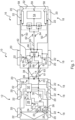
- Fig. 1 shows a combination 10 comprising a towing vehicle 12, which is for example a commercial vehicle and is connected to a trailer vehicle 16 via a drawbar 14.
- the trailer vehicle 16 can thus be towed by the towing vehicle 12.
- the towing vehicle 12 and the trailer vehicle 16 each comprise several axles 18, each of which has two wheels 20.
- Each of the wheels 20 is equipped with a friction brake 22 in order to brake the wheels 20 in the event of a braking request, namely a requested negative acceleration.
- At least one of the axles 18 of the towing vehicle 12 is driven by an internal combustion engine or an electric drive, whereby neither the internal combustion engine nor the electric drive are shown in the drawing for a better overview.
- Fig. 1 are shown.
- a desire to increase speed or to brake is signaled by an operator of the towing vehicle 12 by varying an accelerator pedal position 23 of an accelerator pedal 24 and by varying a brake pedal position 25 of a brake pedal 26.
- the accelerator pedal 24 is connected to a vehicle control unit 28 to transmit the accelerator pedal position 23.
- the brake pedal 26 is connected to a vehicle brake control unit 32 to transmit the brake pedal position 25.
- the vehicle control unit 28 transmits control signals for controlling the drive (not shown) to a bus (not shown) connected to the vehicle control unit 28.
- the vehicle control unit 28 transmits the accelerator pedal position 23 via a connection 34 to the vehicle brake control unit 32.
- the vehicle brake control unit 32 outputs the accelerator pedal position 23 in a message, in particular message EBS 11, on a bus 30 standardized according to ISO 11992.
- the friction brakes 22 of the towing vehicle 12 are connected to the vehicle brake control unit 32, so that in the event of a braking request triggered by the brake pedal 26, this can be converted into braking signals for the friction brakes 22 of the towing vehicle 12.
- the vehicle brake control unit 32 of the towing vehicle 12 generates, on the one hand, a negative acceleration request signal for the trailer vehicle 16, which is transmitted to the trailer brake control unit 42 via the bus 30, and, on the other hand, a brake control pressure 36, which is also transmitted to the trailer vehicle 16 as a negative acceleration request signal via a brake control line 38.
- the transmission of the negative acceleration request signal via the brake control line 38 can be seen as a redundant transmission path.
- a target value of the acceleration request signal is therefore used via the bus 30 to control the friction brakes 22 of the trailer vehicle 16 by the trailer brake control unit 42. If the bus signal fails, the acceleration request signal is received via the brake control line 38.
- the brake control line 38 is connected to a first input 40 of a trailer brake control unit 42 for this purpose.
- a sensor 44 of the trailer brake control unit 42 converts the brake control pressure 36, which is transmitted via the brake control line 38, into an electrical signal 47 and transmits this to a controller 48 of the trailer brake control unit 42.
- Friction brakes 22 of the two axles 18 of the trailer vehicle 16 shown here can be controlled as a function of this signal 47.
- signals, namely brake control signals 50 are output in order to control the friction brakes 22.
- the trailer vehicle 16 has an electric drive 52, which includes a rechargeable battery 54.
- the electric drive includes two converters 56, which use the energy from the battery 54 to supply electric motors 58 with energy in order to generate a positive torque.
- the battery 54, the converters 56 and the electric motors 58 correspond to components 59 of the electric drive 52.
- only one electric motor 58 is provided to drive both wheels 20 of the axle 18, which distributes its drive power to the wheels 20 via a differential gear.
- the electric drive 52 also only includes one converter 56.
- the electric motors 58 can also be operated in generator mode or regenerative mode, so that electrical energy is fed back into the accumulator 54 via the converter 56.
- This regenerative mode is preferably requested by the vehicle brake control unit 32 of the towing vehicle 12 via the trailer brake control unit 42 when the driver requests braking. Accordingly, it can be provided that the use of the friction brakes 22, as described above, only occurs when a requested braking by the electric drive 52 is not sufficient to implement the braking request.
- the electric drive 52 is connected to the trailer brake control unit 42 via another bus 60.
- Controlling the converter 56 specifies, on the one hand, whether the electric motors 58 are to be operated in generator mode or in motor mode and which torque is to be used in this case. In the case of operation of the electric motors 58 in motor mode, this is referred to as a positive torque, while the torque, i.e. a value of the torque, in generator mode of the electric motors 58 is referred to as a negative torque.
- a control signal 62 is sent from the trailer brake control unit 42 to the electric drive 52 via the bus 60.
- the electric drive 52 sends a charge state 64 to the trailer brake control unit 42 in order to be able to inform the trailer brake control unit 42, for example or among other things, which currently available charge quantity or quantity of electrical charge is available, for example as an absolute value, for example in ampere hours, or as a relative value, for example without a unit, to the capacity of the accumulator 54.
- the trailer brake control unit 42 is also configured to generate the control signal 62 depending on the charge state 64 and the received accelerator pedal position 23 and to output it via an interface 66 of the bus 30, with which the charge state 64 is also received.
- the trailer brake control unit 42 is accordingly connected to the bus 30 via a further input 68 in order to receive the accelerator pedal position 23.
- the bus 30 corresponds to a CAN bus and the input 68 to an interface for the CAN bus. Accordingly, in addition to receiving the accelerator pedal position 23 with the trailer brake control unit 42, it is also possible to transmit the control signal 62 to the vehicle brake control unit 32 of the towing vehicle 12. This is done, for example, as a relative value 61 or as an absolute value 63 of a control torque value of the control signal 62.
- the current speed 69 is also transmitted via the bus 30.
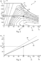
- Fig. 2 shows an efficiency map 70 of the electric motor(s) 58 of the electric drive 52.
- the efficiency map 70 shows the efficiency range by contour lines 72 at the vehicle speed 76 plotted on a horizontal axis 74 and torque values 80 plotted on a vertical axis 78.
- a torque characteristic curve 82 is predetermined, which was determined in such a way that it indicates maximum torque values 84 of the electric drive 52, namely its electric motors 58, depending on the speed 76, at which the electric drive 52 can be operated advantageously, for example with nominal power.
- the torque characteristic curve 82 assigns So, an example maximum torque value 84 at a current speed 86 of 80 kilometers per hour is assigned to the maximum torque 88 of about 570 Newton meters.
- the torque characteristic 82 can and will also be considered as the S1 characteristic in the following.
- a maximum torque value 84 therefore corresponds to the torque value 88 that lies on the torque characteristic 82, namely the S1 characteristic, at a speed 86.
- the maximum torque value 84 is accordingly determined according to M max ( S 1, v ).
- FIG. 3 an accelerator pedal position characteristic curve 90, which assigns a percentage value of an accelerator pedal position, shown on the vertical axis 94, to each speed value 76 shown on the horizontal axis 92.
- the accelerator pedal position characteristic curve 90 thus assigns an expected accelerator pedal position 96 to each speed 76 of the vehicle, which is expected when driving straight ahead at a constant speed on a level stretch of road.
- the accelerator pedal position characteristic curve 90 is also stored in the trailer brake control unit 42, for example, and is adjusted by the trailer brake control unit 42 depending on a mass that changes, for example, due to the loading of the trailer vehicle 16.
- a steeper curve is shown by the dashed line 98 for a comparatively higher mass.
- step 100 shows that a current speed 69 is first determined or recorded.
- step 104 a maximum torque value 84 is then determined based on the current speed 69 and a torque characteristic curve 82.
- step 106 an expected accelerator pedal position 96 is determined using an accelerator pedal position characteristic curve 90 based on the current speed 69.
- the accelerator pedal position characteristic curve 90 is previously determined in a step 105 depending on conditions 107 of the trailer vehicle 16, such as the current mass of the trailer vehicle 16, or a stored accelerator pedal position characteristic curve 90 is adjusted.
- the expected accelerator pedal position 96 is compared in a step 108 with an accelerator pedal position 23 received in a step 109.
- the comparison is carried out, for example, according to the following formula: 100 % 100 % ⁇ A * ⁇ A ⁇ A * .
- A is the received accelerator pedal position 23, whereas A * is the expected accelerator pedal position 96.
- the comparison result 110 is then fed to a step 112 as well as the maximum torque value 84 and these are related to one another, for example by multiplying them with one another, so that a control torque value 114 is output from step 112.
- the state of charge 64 of an accumulator 54 of the electric drive 52 is then used to adjust the control torque value 114.
- a threshold value 119 or threshold range 120 as well as a predefined value 121 and a predefined relative value 122 are supplied.
- the adjusted control torque value 115 is output in a step 118 as a control signal 62.
- the control signal 62 includes, for example, a torque value that is fed to the inverter 56 or the inverters 56 of the electric drive 52 and which are controlled in step 124.
- the control signal 62 is also output to a vehicle brake control unit 32 of the towing vehicle 12, which generates and outputs a request signal 126 for the vehicle control unit 28 in a step 125.
Landscapes
- Engineering & Computer Science (AREA)
- Transportation (AREA)
- Mechanical Engineering (AREA)
- Power Engineering (AREA)
- Chemical & Material Sciences (AREA)
- Combustion & Propulsion (AREA)
- Electric Propulsion And Braking For Vehicles (AREA)
- Regulating Braking Force (AREA)
Claims (13)
- Procédé pour un véhicule remorqué (16) pouvant être accouplé à un véhicule tracteur (12) comportant un entraînement (52) électrique destiné à commander (120) l'entraînement (52) électrique, comprenant les étapes de :- réception (109), en provenance d'un véhicule tracteur (12), d'une position actuelle de pédale d'accélérateur (23) au moyen d'un appareil de commande de frein de remorque (42) du véhicule remorqué (16),- génération (104, 106, 108, 112, 116), au moyen de l'appareil de commande de frein de remorque (42), d'un signal de commande (62) pour l'entraînement (52) électrique en fonction de la position actuelle de pédale d'accélérateur (23) reçue et- commande (120) de l'entraînement (52) électrique au moyen du signal de commande (62) généré,caractérisé en ce quela position de pédale d'accélérateur (23) est reçue par l'intermédiaire d'un bus CAN ISO 11992-2 (30), notamment dans le message EBS 11, etle signal de commande (62) est délivré à un appareil de commande de frein de véhicule (32) du véhicule tracteur (12) par l'intermédiaire du bus CAN ISO 11992-2 (30), notamment dans le message 21 et/ou 23 en tant que valeur absolue (63) dans le message 23 et en tant que valeur relative (61) dans le message 21, et un signal de demande (126) pour un appareil de commande de véhicule (28) est généré dans l'appareil de commande de frein de véhicule (32) en fonction du signal de commande (62).
- Procédé selon la revendication 1, dans lequel en outre un état de charge (64) d'au moins un accumulateur (54) de l'entraînement (52) électrique est détecté par l'appareil de commande de frein de remorque (42), et le signal de commande (62) est généré au moyen de l'appareil de commande de frein de remorque (42) en fonction de la position de pédale d'accélérateur (23) et de l'état de charge (64) détecté.
- Procédé selon la revendication 1 ou 2, dans lequel la génération du signal de commande (62) comprend :- la détection ou la fourniture (100) d'une vitesse (69) actuelle du véhicule remorqué (16) dans l'appareil de commande de frein de remorque (42),- la détermination (104) d'une valeur de couple (84) maximale de l'entraînement (52) électrique à l'aide d'une caractéristique de couple (82) comportant des valeurs de couple (84) maximales dépendant de la vitesse et la vitesse (69) actuelle détectée ou fournie et- la détermination (112) d'une valeur de couple de commande (114) en fonction de la position de pédale d'accélérateur (23) et de la valeur de couple (84) maximale déterminée,- la délivrance (118), à l'entraînement (52) électrique, de la valeur de couple de commande (114) déterminée ou d'une valeur de couple de commande (115) adaptée dépendant de la valeur de couple de commande (114) déterminée, en tant que signal de commande (62).
- Procédé selon la revendication 3, dans lequel un état de charge (64) d'un accumulateur (54) de l'entraînement (52) électrique est détecté par l'appareil de commande de frein de remorque (42), et la valeur de couple de commande (114) générée par l'appareil de commande de frein de remorque (42) est adaptée (116) en fonction de l'état de charge (64) détecté et la valeur de couple de commande (115) adaptée est délivrée à l'entraînement (52) électrique en tant que signal de commande (62).
- Procédé selon la revendication 4, dans lequel l'adaptation (116) de la valeur de couple de commande (114) est effectuée de telle sorte que,- dans le cas où l'état de charge (64) de l'au moins un accumulateur (54) est supérieur à une valeur seuil (119) prédéfinie ou une plage de valeurs seuils (120) prédéfinie, la valeur de couple de commande (114) est augmentée, en particulier par une valeur (121) prédéfinie ou une valeur relative (122) prédéfinie de la valeur de couple de commande (114), et- dans le cas où l'état de charge (64) de l'au moins un accumulateur (54) est inférieur à la ou à une autre valeur seuil (119) prédéfinie ou une plage de valeurs seuils (120) prédéfinie de l'état de charge (64), la valeur de couple de commande (114) est diminuée, en particulier par la ou une autre valeur (121) prédéfinie ou la ou une autre valeur relative (122) prédéfinie de la valeur de couple de commande (114).
- Procédé selon l'une des revendications précédentes, dans lequel la génération du signal de commande (62) comprend :- la détermination (106) d'une position de pédale d'accélérateur (96) actuellement attendue du véhicule tracteur (12) du véhicule remorqué (16),- la comparaison (108) de la position actuelle de pédale d'accélérateur (23) reçue à la position attendue de pédale d'accélérateur (96) pour déterminer un résultat de comparaison (110) et- la génération (112) de la valeur de couple de commande (114) pour la délivrer en tant que signal de commande (62) pour l'entraînement (52) électrique en fonction, en outre, du résultat de comparaison (110).
- Procédé selon la revendication 6, dans lequel la détermination (106) d'une position de pédale d'accélérateur (96) actuellement attendue du véhicule tracteur (12) est déterminée en fonction d'une caractéristique de position de pédale d'accélérateur (90) qui indique une position de pédale d'accélérateur (96) attendue en fonction d'une vitesse (69) actuelle du véhicule remorqué (16).
- Procédé selon la revendication 7, dans lequel la caractéristique de position de pédale d'accélérateur (90) est adaptée (105) en fonction d'autres états (107) du véhicule (12) ou du véhicule remorqué (16), en particulier de la masse actuelle du véhicule remorqué (16).
- Procédé selon l'une des revendications précédentes, dans lequel la valeur de couple de commande (114) est déterminée par :

M* est la valeur de couple de commande (114) déterminée, A* correspond à la position attendue de pédale d'accélérateur (96), A correspond à la position de pédale d'accélérateur (23) reçue et Mmax (S1, v) correspond à la valeur de couple (84) maximale en fonction de la vitesse (69) actuelle. - Appareil de commande de frein de véhicule (32) pour un véhicule tracteur (12), dans lequel l'appareil de commande de frein de véhicule (32) est configuré pour délivrer une position de pédale d'accélérateur (23) à l'aide d'un bus CAN ISO 11992-2 (30), notamment dans le message EBS 11, et pour recevoir, en provenance d'un appareil de commande de frein de remorque (42), un signal de commande (62) destiné à commander l'entraînement (52) électrique d'un véhicule remorqué (16) pouvant être accouplé au véhicule tracteur (12) par l'intermédiaire du bus CAN ISO 11992-2, notamment dans le message 21 et/ou 23, et dans lequel l'appareil de commande de frein de véhicule (32) est configuré pour délivrer, en fonction du signal de commande (62), un signal de demande (114) pour un appareil de commande de véhicule (28) du véhicule tracteur (12).
- Appareil de commande de frein de remorque (42) pour un véhicule remorqué (16), lequel appareil de commande de frein de remorque est configuré pour mettre en oeuvre un procédé selon l'une des revendications 1 à 9, notamment pour recevoir une position de pédale d'accélérateur (23) en provenance d'un véhicule tracteur (12), pour générer un signal de commande (62) en fonction de la position de pédale d'accélérateur (23) reçue et pour le délivrer à un entraînement (52) électrique du véhicule remorqué (16).
- Véhicule (12) comportant un appareil de commande de frein de véhicule (32) selon la revendication 10 ou un appareil de commande de frein de remorque (42) selon la revendication 11.
- Produit programme d'ordinateur qui, mis en oeuvre sur un appareil de commande de frein de remorque (42) selon la revendication 11, met en oeuvre le procédé selon l'une des revendications 1 à 9.
Applications Claiming Priority (2)
| Application Number | Priority Date | Filing Date | Title |
|---|---|---|---|
| DE102019100017.3A DE102019100017A1 (de) | 2019-01-02 | 2019-01-02 | Anhängerfahrzeug und Anhängerbremssteuergerät sowie Verfahren und Software dafür |
| PCT/EP2019/085469 WO2020141065A1 (fr) | 2019-01-02 | 2019-12-17 | Véhicule à remorque et unité de commande de frein de remorque ainsi que procédé et produit programme informatique associés |
Publications (2)
| Publication Number | Publication Date |
|---|---|
| EP3906177A1 EP3906177A1 (fr) | 2021-11-10 |
| EP3906177B1 true EP3906177B1 (fr) | 2024-10-09 |
Family
ID=69147604
Family Applications (1)
| Application Number | Title | Priority Date | Filing Date |
|---|---|---|---|
| EP19832872.6A Active EP3906177B1 (fr) | 2019-01-02 | 2019-12-17 | Remorque et dispositif de contrôle de freinage du remorque, procédé et produit de programme informatique |
Country Status (5)
| Country | Link |
|---|---|
| US (1) | US12116059B2 (fr) |
| EP (1) | EP3906177B1 (fr) |
| CN (1) | CN113226830B (fr) |
| DE (1) | DE102019100017A1 (fr) |
| WO (1) | WO2020141065A1 (fr) |
Families Citing this family (12)
| Publication number | Priority date | Publication date | Assignee | Title |
|---|---|---|---|---|
| DE102019217707B4 (de) * | 2019-11-18 | 2021-10-14 | Zf Friedrichshafen Ag | Verfahren und Steuereinrichtung zur Reichweitenoptimierung eines Gespanns bestehend aus einem antreibbaren Zugfahrzeug und einem antreibbaren Anhänger |
| PT3971045T (pt) * | 2020-09-17 | 2023-03-22 | Nuewiel Gmbh | Sistema de um reboque motorizado e uma barra de reboque |
| DE102021106670A1 (de) * | 2021-03-18 | 2022-09-22 | Zf Cv Systems Europe Bv | Verfahren und Umfeld-Erfassungssystem zum Erzeugen eines Umgebungsbildes eines mehrgliedrigen Gesamtfahrzeugs |
| CN113548025B (zh) * | 2021-08-10 | 2024-10-01 | 安徽理工大学 | 一种牵挂车气电耦合式协同制动系统 |
| DE102022100252A1 (de) | 2022-01-06 | 2023-07-06 | Zf Cv Systems Global Gmbh | Verfahren zum Steuern eines elektrischen Antriebs eines Fahrzeugs sowie System und Gespann zum Ausführen des Verfahrens |
| JP7726302B2 (ja) * | 2022-01-18 | 2025-08-20 | 日産自動車株式会社 | 電動車両の制御方法、及び、電動車両の制御装置 |
| WO2023237184A1 (fr) * | 2022-06-07 | 2023-12-14 | Volvo Truck Corporation | Procédé d'attribution de commande distribuée pour combinaisons de véhicules à unités multiples |
| DE102022124559A1 (de) * | 2022-09-23 | 2024-03-28 | Zf Cv Systems Global Gmbh | Anhängernetzwerksystem zur Datenkommunikation in einem Anhängerfahrzeug sowie Anhängerfahrzeug damit und Verfahren dafür |
| WO2024086611A1 (fr) * | 2022-10-18 | 2024-04-25 | Mobius Rv, Llc | Habitat tractable à alimentation electrique |
| CN115743131B (zh) * | 2022-12-27 | 2025-12-19 | 中国重汽集团济南动力有限公司 | 一种E-power架构车辆EBS模块交互控制方法及系统 |
| DE102023109504A1 (de) * | 2023-04-14 | 2024-10-17 | Zf Cv Systems Global Gmbh | Verfahren zum Betreiben eines Antriebs eines Anhängers sowie ein Anhänger für ein Fahrzeuggespann |
| US20250222917A1 (en) * | 2024-01-08 | 2025-07-10 | GM Global Technology Operations LLC | System and method of towing controls for creating a hybrid vehicle from an electric vehicle and a conventional vehicle |
Citations (5)
| Publication number | Priority date | Publication date | Assignee | Title |
|---|---|---|---|---|
| EP2394890A1 (fr) * | 2010-06-10 | 2011-12-14 | Iveco S.p.A. | Remorque de véhicule équipée d'un système de traction additionnel, véhicule doté de ladite remorque et procédé de gestion du système de traction additionnel |
| US20160318406A1 (en) * | 2015-05-01 | 2016-11-03 | Hyliion Inc. | Motor vehicle accessory to increase power supply and reduce fuel requirements |
| US20180086227A1 (en) * | 2015-05-01 | 2018-03-29 | Hyliion Inc. | Trailer-based energy capture and management |
| EP2842814B1 (fr) * | 2013-08-29 | 2018-06-06 | MAN Truck & Bus AG | Remorque pour véhicule |
| DE102016123350A1 (de) * | 2016-12-02 | 2018-06-07 | Saf-Holland Gmbh | Sattelauflieger, Sattelzug und Verfahren zum Bremsen eines Sattelaufliegers |
Family Cites Families (9)
| Publication number | Priority date | Publication date | Assignee | Title |
|---|---|---|---|---|
| US6516925B1 (en) * | 2000-09-28 | 2003-02-11 | Ford Global Technologies, Inc. | System and method for braking a towed conveyance |
| DE102010034745A1 (de) | 2009-12-18 | 2011-06-22 | WABCO GmbH, 30453 | Verfahren zum Signalisieren eines Bremsvorgangs an einem Anhängefahrzeug, Steuereinrichtung hierfür sowie Lichtanlage, Anhängefahrzeugbremsanlage und Anhängefahrzeug mit dieser Steuereinrichtung |
| US7332881B2 (en) | 2004-10-28 | 2008-02-19 | Textron Inc. | AC drive system for electrically operated vehicle |
| US8469125B2 (en) * | 2011-03-25 | 2013-06-25 | Honda Motor Co., Ltd. | System and method for controlling a trailer connected to a vehicle |
| DE102012223866A1 (de) | 2012-12-19 | 2014-07-17 | Bayerische Motoren Werke Aktiengesellschaft | Einrichtung zum Vermeiden des Rollens für ein ein elektrisches Antriebssystem umfassendes Kraftfahrzeug auf einer geneigten Fläche |
| EP3368386A1 (fr) * | 2015-10-30 | 2018-09-05 | Robert Bosch GmbH | Système de freinage antiblocage de remorque |
| DE102015222981A1 (de) * | 2015-11-20 | 2017-05-24 | Robert Bosch Gmbh | Hybridsystem für ein Kraftfahrzeug mit einem Anhänger |
| US10518831B2 (en) * | 2017-04-21 | 2019-12-31 | Wrightspeed, Inc. | Self-powered actively steerable converter dollies for long combination vehicles |
| DE102017010356A1 (de) * | 2017-09-20 | 2019-03-21 | Wabco Gmbh | Datensystem, Datenübertragungssystem sowie Verfahren zur Datenübertragung für ein Zug-Fahrzeug und/oder Anhänger-Fahrzeug |
-
2019
- 2019-01-02 DE DE102019100017.3A patent/DE102019100017A1/de not_active Withdrawn
- 2019-12-17 US US17/419,302 patent/US12116059B2/en active Active
- 2019-12-17 WO PCT/EP2019/085469 patent/WO2020141065A1/fr not_active Ceased
- 2019-12-17 EP EP19832872.6A patent/EP3906177B1/fr active Active
- 2019-12-17 CN CN201980086458.4A patent/CN113226830B/zh active Active
Patent Citations (5)
| Publication number | Priority date | Publication date | Assignee | Title |
|---|---|---|---|---|
| EP2394890A1 (fr) * | 2010-06-10 | 2011-12-14 | Iveco S.p.A. | Remorque de véhicule équipée d'un système de traction additionnel, véhicule doté de ladite remorque et procédé de gestion du système de traction additionnel |
| EP2842814B1 (fr) * | 2013-08-29 | 2018-06-06 | MAN Truck & Bus AG | Remorque pour véhicule |
| US20160318406A1 (en) * | 2015-05-01 | 2016-11-03 | Hyliion Inc. | Motor vehicle accessory to increase power supply and reduce fuel requirements |
| US20180086227A1 (en) * | 2015-05-01 | 2018-03-29 | Hyliion Inc. | Trailer-based energy capture and management |
| DE102016123350A1 (de) * | 2016-12-02 | 2018-06-07 | Saf-Holland Gmbh | Sattelauflieger, Sattelzug und Verfahren zum Bremsen eines Sattelaufliegers |
Also Published As
| Publication number | Publication date |
|---|---|
| DE102019100017A1 (de) | 2020-07-02 |
| US20220097786A1 (en) | 2022-03-31 |
| WO2020141065A1 (fr) | 2020-07-09 |
| EP3906177A1 (fr) | 2021-11-10 |
| CN113226830A (zh) | 2021-08-06 |
| US12116059B2 (en) | 2024-10-15 |
| CN113226830B (zh) | 2025-02-28 |
Similar Documents
| Publication | Publication Date | Title |
|---|---|---|
| EP3906177B1 (fr) | Remorque et dispositif de contrôle de freinage du remorque, procédé et produit de programme informatique | |
| EP4003771B1 (fr) | Méthode d'assistance de traction d'un tracteur tirant une remorque | |
| DE102021123565A1 (de) | Fahrzeugstart am berg im einpedalfahrmodus | |
| DE102018121439A1 (de) | Anhängerbremssteuergerät sowie Verfahren und Software dafür und Anhängerfahrzeug damit | |
| EP4126583B1 (fr) | Procédé et dispositif de contrôle d'entraînement électrique d'une remorque | |
| EP4054905B1 (fr) | Méthode et système pour freiner un véhicule utilitaire avec un propulsion électrique | |
| EP4003774B1 (fr) | Procédé et dispositif pour activer un entraînement électrique d'un véhicule tracté | |
| DE19810656A1 (de) | Verfahren und Vorrichtung zum statischen oder dynamischen Ermitteln von Sollwerten für Bremskräfte oder Bremsmomente | |
| DE102019127034A1 (de) | Schätzung der fahrzeuggeschwindigkeit bei fahrzeugen mit allradantrieb | |
| DE102014103785B4 (de) | Stromerzeugungssteuerungsvorrichtung eines Hybridfahrzeugs | |
| DE102013106319A1 (de) | Fahrzeug und Verfahren zur Leistungsverbesserung bei niedrigen Batteriegrenzen | |
| EP4385790A1 (fr) | Dispositif et procédé de régulation continue du couple de roue dans des véhicules électriques à batterie au moyen de machines-moyeus et système de freinage découplé | |
| DE102010054620A1 (de) | Verfahren zur Bestimmung von Bremsmomenten eines Fahrzeugs mit Traktionsbatterie | |
| EP4419373A1 (fr) | Dispositif destiné à exciter un entraînement électrique d'un véhicule tracté ainsi que système le comprenant et procédé associé | |
| DE102020106320A1 (de) | Verfahren zum Betreiben eines elektrischen Antriebssystems eines Anhängefahrzeugs einer Zugfahrzeug-Anhängefahrzeug-Kombination sowie elektrisches Antriebssystem | |
| WO2022128835A1 (fr) | Procédé de distribution d'un couple requis pour entraîner un véhicule à roues | |
| DE102006055799B4 (de) | Verfahren zum regenerativen Bremsen eines Fahrzeugs mit mehreren Bremssystemen | |
| DE102022116594A1 (de) | Verfahren zum Ansteuern eines elektrischen Antriebs eines Anhängerfahrzeugs sowie Anhängersteuergerät zum Ausführen des Verfahrens | |
| DE102022116593A1 (de) | Verfahren zum Laden eines Energiespeichers eines Anhängerfahrzeugs sowie Steuergerät und Anhängerfahrzeug | |
| DE102022116596A1 (de) | Anhängersteuergerät zum Ansteuern eines elektrischen Antriebs eines Anhängerfahrzeugs sowie Verfahren zum Ansteuern des elektrischen Antriebs mit dem Anhängersteuergerät | |
| DE102022100252A1 (de) | Verfahren zum Steuern eines elektrischen Antriebs eines Fahrzeugs sowie System und Gespann zum Ausführen des Verfahrens | |
| DE102012208462B4 (de) | Vorrichtung zum Betreiben eines Antriebsstrangs | |
| DE102019217707B4 (de) | Verfahren und Steuereinrichtung zur Reichweitenoptimierung eines Gespanns bestehend aus einem antreibbaren Zugfahrzeug und einem antreibbaren Anhänger | |
| DE102021133757A1 (de) | Verfahren zum Bremsen eines Anhängerfahrzeugs mit einem elektrischen Antrieb und Reibbremsen sowie Bremssystem zum Ausführen des Verfahrens | |
| DE102024105209B4 (de) | Verfahren zum Abschleppen eines zweiten Fahrzeugs durch ein erstes Fahrzeug und Elektrofahrzeug |
Legal Events
| Date | Code | Title | Description |
|---|---|---|---|
| STAA | Information on the status of an ep patent application or granted ep patent |
Free format text: STATUS: UNKNOWN |
|
| STAA | Information on the status of an ep patent application or granted ep patent |
Free format text: STATUS: THE INTERNATIONAL PUBLICATION HAS BEEN MADE |
|
| PUAI | Public reference made under article 153(3) epc to a published international application that has entered the european phase |
Free format text: ORIGINAL CODE: 0009012 |
|
| STAA | Information on the status of an ep patent application or granted ep patent |
Free format text: STATUS: REQUEST FOR EXAMINATION WAS MADE |
|
| 17P | Request for examination filed |
Effective date: 20210802 |
|
| AK | Designated contracting states |
Kind code of ref document: A1 Designated state(s): AL AT BE BG CH CY CZ DE DK EE ES FI FR GB GR HR HU IE IS IT LI LT LU LV MC MK MT NL NO PL PT RO RS SE SI SK SM TR |
|
| RAP1 | Party data changed (applicant data changed or rights of an application transferred) |
Owner name: ZF CV SYSTEMS EUROPE BV |
|
| DAV | Request for validation of the european patent (deleted) | ||
| DAX | Request for extension of the european patent (deleted) | ||
| STAA | Information on the status of an ep patent application or granted ep patent |
Free format text: STATUS: EXAMINATION IS IN PROGRESS |
|
| 17Q | First examination report despatched |
Effective date: 20221209 |
|
| REG | Reference to a national code |
Ref country code: DE Ipc: B60K0001040000 Ref country code: DE Ref legal event code: R079 Ref document number: 502019012287 Country of ref document: DE Free format text: PREVIOUS MAIN CLASS: B60L0007000000 Ipc: B60K0001040000 |
|
| GRAP | Despatch of communication of intention to grant a patent |
Free format text: ORIGINAL CODE: EPIDOSNIGR1 |
|
| STAA | Information on the status of an ep patent application or granted ep patent |
Free format text: STATUS: GRANT OF PATENT IS INTENDED |
|
| RIC1 | Information provided on ipc code assigned before grant |
Ipc: B60L 15/38 20060101ALI20240530BHEP Ipc: B60T 13/66 20060101ALI20240530BHEP Ipc: B62D 59/04 20060101ALI20240530BHEP Ipc: B60T 7/20 20060101ALI20240530BHEP Ipc: B60K 1/00 20060101ALI20240530BHEP Ipc: B60T 8/17 20060101ALI20240530BHEP Ipc: B60K 7/00 20060101ALI20240530BHEP Ipc: B60L 15/20 20060101ALI20240530BHEP Ipc: B60L 7/00 20060101ALI20240530BHEP Ipc: B60K 1/04 20190101AFI20240530BHEP |
|
| GRAJ | Information related to disapproval of communication of intention to grant by the applicant or resumption of examination proceedings by the epo deleted |
Free format text: ORIGINAL CODE: EPIDOSDIGR1 |
|
| STAA | Information on the status of an ep patent application or granted ep patent |
Free format text: STATUS: EXAMINATION IS IN PROGRESS |
|
| GRAP | Despatch of communication of intention to grant a patent |
Free format text: ORIGINAL CODE: EPIDOSNIGR1 |
|
| STAA | Information on the status of an ep patent application or granted ep patent |
Free format text: STATUS: GRANT OF PATENT IS INTENDED |
|
| INTG | Intention to grant announced |
Effective date: 20240617 |
|
| INTC | Intention to grant announced (deleted) | ||
| INTG | Intention to grant announced |
Effective date: 20240715 |
|
| GRAS | Grant fee paid |
Free format text: ORIGINAL CODE: EPIDOSNIGR3 |
|
| GRAA | (expected) grant |
Free format text: ORIGINAL CODE: 0009210 |
|
| STAA | Information on the status of an ep patent application or granted ep patent |
Free format text: STATUS: THE PATENT HAS BEEN GRANTED |
|
| AK | Designated contracting states |
Kind code of ref document: B1 Designated state(s): AL AT BE BG CH CY CZ DE DK EE ES FI FR GB GR HR HU IE IS IT LI LT LU LV MC MK MT NL NO PL PT RO RS SE SI SK SM TR |
|
| REG | Reference to a national code |
Ref country code: CH Ref legal event code: EP |
|
| REG | Reference to a national code |
Ref country code: DE Ref legal event code: R096 Ref document number: 502019012287 Country of ref document: DE |
|
| REG | Reference to a national code |
Ref country code: IE Ref legal event code: FG4D Free format text: LANGUAGE OF EP DOCUMENT: GERMAN |
|
| REG | Reference to a national code |
Ref country code: LT Ref legal event code: MG9D |
|
| REG | Reference to a national code |
Ref country code: NL Ref legal event code: MP Effective date: 20241009 |
|
| PG25 | Lapsed in a contracting state [announced via postgrant information from national office to epo] |
Ref country code: NL Free format text: LAPSE BECAUSE OF FAILURE TO SUBMIT A TRANSLATION OF THE DESCRIPTION OR TO PAY THE FEE WITHIN THE PRESCRIBED TIME-LIMIT Effective date: 20241009 |
|
| PG25 | Lapsed in a contracting state [announced via postgrant information from national office to epo] |
Ref country code: NL Free format text: LAPSE BECAUSE OF FAILURE TO SUBMIT A TRANSLATION OF THE DESCRIPTION OR TO PAY THE FEE WITHIN THE PRESCRIBED TIME-LIMIT Effective date: 20241009 |
|
| PG25 | Lapsed in a contracting state [announced via postgrant information from national office to epo] |
Ref country code: IS Free format text: LAPSE BECAUSE OF FAILURE TO SUBMIT A TRANSLATION OF THE DESCRIPTION OR TO PAY THE FEE WITHIN THE PRESCRIBED TIME-LIMIT Effective date: 20250209 Ref country code: PT Free format text: LAPSE BECAUSE OF FAILURE TO SUBMIT A TRANSLATION OF THE DESCRIPTION OR TO PAY THE FEE WITHIN THE PRESCRIBED TIME-LIMIT Effective date: 20250210 Ref country code: HR Free format text: LAPSE BECAUSE OF FAILURE TO SUBMIT A TRANSLATION OF THE DESCRIPTION OR TO PAY THE FEE WITHIN THE PRESCRIBED TIME-LIMIT Effective date: 20241009 |
|
| PG25 | Lapsed in a contracting state [announced via postgrant information from national office to epo] |
Ref country code: FI Free format text: LAPSE BECAUSE OF FAILURE TO SUBMIT A TRANSLATION OF THE DESCRIPTION OR TO PAY THE FEE WITHIN THE PRESCRIBED TIME-LIMIT Effective date: 20241009 |
|
| PG25 | Lapsed in a contracting state [announced via postgrant information from national office to epo] |
Ref country code: BG Free format text: LAPSE BECAUSE OF FAILURE TO SUBMIT A TRANSLATION OF THE DESCRIPTION OR TO PAY THE FEE WITHIN THE PRESCRIBED TIME-LIMIT Effective date: 20241009 |
|
| PG25 | Lapsed in a contracting state [announced via postgrant information from national office to epo] |
Ref country code: ES Free format text: LAPSE BECAUSE OF FAILURE TO SUBMIT A TRANSLATION OF THE DESCRIPTION OR TO PAY THE FEE WITHIN THE PRESCRIBED TIME-LIMIT Effective date: 20241009 |
|
| PG25 | Lapsed in a contracting state [announced via postgrant information from national office to epo] |
Ref country code: NO Free format text: LAPSE BECAUSE OF FAILURE TO SUBMIT A TRANSLATION OF THE DESCRIPTION OR TO PAY THE FEE WITHIN THE PRESCRIBED TIME-LIMIT Effective date: 20250109 |
|
| PG25 | Lapsed in a contracting state [announced via postgrant information from national office to epo] |
Ref country code: GR Free format text: LAPSE BECAUSE OF FAILURE TO SUBMIT A TRANSLATION OF THE DESCRIPTION OR TO PAY THE FEE WITHIN THE PRESCRIBED TIME-LIMIT Effective date: 20250110 Ref country code: LV Free format text: LAPSE BECAUSE OF FAILURE TO SUBMIT A TRANSLATION OF THE DESCRIPTION OR TO PAY THE FEE WITHIN THE PRESCRIBED TIME-LIMIT Effective date: 20241009 |
|
| PG25 | Lapsed in a contracting state [announced via postgrant information from national office to epo] |
Ref country code: PL Free format text: LAPSE BECAUSE OF FAILURE TO SUBMIT A TRANSLATION OF THE DESCRIPTION OR TO PAY THE FEE WITHIN THE PRESCRIBED TIME-LIMIT Effective date: 20241009 |
|
| PG25 | Lapsed in a contracting state [announced via postgrant information from national office to epo] |
Ref country code: RS Free format text: LAPSE BECAUSE OF FAILURE TO SUBMIT A TRANSLATION OF THE DESCRIPTION OR TO PAY THE FEE WITHIN THE PRESCRIBED TIME-LIMIT Effective date: 20250109 |
|
| PG25 | Lapsed in a contracting state [announced via postgrant information from national office to epo] |
Ref country code: SM Free format text: LAPSE BECAUSE OF FAILURE TO SUBMIT A TRANSLATION OF THE DESCRIPTION OR TO PAY THE FEE WITHIN THE PRESCRIBED TIME-LIMIT Effective date: 20241009 |
|
| PG25 | Lapsed in a contracting state [announced via postgrant information from national office to epo] |
Ref country code: MC Free format text: LAPSE BECAUSE OF FAILURE TO SUBMIT A TRANSLATION OF THE DESCRIPTION OR TO PAY THE FEE WITHIN THE PRESCRIBED TIME-LIMIT Effective date: 20241009 |
|
| PG25 | Lapsed in a contracting state [announced via postgrant information from national office to epo] |
Ref country code: DK Free format text: LAPSE BECAUSE OF FAILURE TO SUBMIT A TRANSLATION OF THE DESCRIPTION OR TO PAY THE FEE WITHIN THE PRESCRIBED TIME-LIMIT Effective date: 20241009 |
|
| REG | Reference to a national code |
Ref country code: DE Ref legal event code: R097 Ref document number: 502019012287 Country of ref document: DE |
|
| PG25 | Lapsed in a contracting state [announced via postgrant information from national office to epo] |
Ref country code: EE Free format text: LAPSE BECAUSE OF FAILURE TO SUBMIT A TRANSLATION OF THE DESCRIPTION OR TO PAY THE FEE WITHIN THE PRESCRIBED TIME-LIMIT Effective date: 20241009 |
|
| PG25 | Lapsed in a contracting state [announced via postgrant information from national office to epo] |
Ref country code: RO Free format text: LAPSE BECAUSE OF FAILURE TO SUBMIT A TRANSLATION OF THE DESCRIPTION OR TO PAY THE FEE WITHIN THE PRESCRIBED TIME-LIMIT Effective date: 20241009 |
|
| PG25 | Lapsed in a contracting state [announced via postgrant information from national office to epo] |
Ref country code: SK Free format text: LAPSE BECAUSE OF FAILURE TO SUBMIT A TRANSLATION OF THE DESCRIPTION OR TO PAY THE FEE WITHIN THE PRESCRIBED TIME-LIMIT Effective date: 20241009 |
|
| PG25 | Lapsed in a contracting state [announced via postgrant information from national office to epo] |
Ref country code: CZ Free format text: LAPSE BECAUSE OF FAILURE TO SUBMIT A TRANSLATION OF THE DESCRIPTION OR TO PAY THE FEE WITHIN THE PRESCRIBED TIME-LIMIT Effective date: 20241009 |
|
| PG25 | Lapsed in a contracting state [announced via postgrant information from national office to epo] |
Ref country code: IT Free format text: LAPSE BECAUSE OF FAILURE TO SUBMIT A TRANSLATION OF THE DESCRIPTION OR TO PAY THE FEE WITHIN THE PRESCRIBED TIME-LIMIT Effective date: 20241009 |
|
| REG | Reference to a national code |
Ref country code: CH Ref legal event code: PL |
|
| PLBE | No opposition filed within time limit |
Free format text: ORIGINAL CODE: 0009261 |
|
| STAA | Information on the status of an ep patent application or granted ep patent |
Free format text: STATUS: NO OPPOSITION FILED WITHIN TIME LIMIT |
|
| PG25 | Lapsed in a contracting state [announced via postgrant information from national office to epo] |
Ref country code: LU Free format text: LAPSE BECAUSE OF NON-PAYMENT OF DUE FEES Effective date: 20241217 |
|
| PG25 | Lapsed in a contracting state [announced via postgrant information from national office to epo] |
Ref country code: SE Free format text: LAPSE BECAUSE OF FAILURE TO SUBMIT A TRANSLATION OF THE DESCRIPTION OR TO PAY THE FEE WITHIN THE PRESCRIBED TIME-LIMIT Effective date: 20241009 |
|
| 26N | No opposition filed |
Effective date: 20250710 |
|
| REG | Reference to a national code |
Ref country code: BE Ref legal event code: MM Effective date: 20241231 |
|
| PG25 | Lapsed in a contracting state [announced via postgrant information from national office to epo] |
Ref country code: BE Free format text: LAPSE BECAUSE OF NON-PAYMENT OF DUE FEES Effective date: 20241231 |
|
| PG25 | Lapsed in a contracting state [announced via postgrant information from national office to epo] |
Ref country code: CH Free format text: LAPSE BECAUSE OF NON-PAYMENT OF DUE FEES Effective date: 20241231 |
|
| PG25 | Lapsed in a contracting state [announced via postgrant information from national office to epo] |
Ref country code: IE Free format text: LAPSE BECAUSE OF NON-PAYMENT OF DUE FEES Effective date: 20241217 |
|
| PGFP | Annual fee paid to national office [announced via postgrant information from national office to epo] |
Ref country code: DE Payment date: 20250930 Year of fee payment: 7 |
|
| PGFP | Annual fee paid to national office [announced via postgrant information from national office to epo] |
Ref country code: GB Payment date: 20251001 Year of fee payment: 7 |
|
| PGFP | Annual fee paid to national office [announced via postgrant information from national office to epo] |
Ref country code: FR Payment date: 20251008 Year of fee payment: 7 |
|
| REG | Reference to a national code |
Ref country code: AT Ref legal event code: MM01 Ref document number: 1730225 Country of ref document: AT Kind code of ref document: T Effective date: 20241217 |
|
| PG25 | Lapsed in a contracting state [announced via postgrant information from national office to epo] |
Ref country code: AT Free format text: LAPSE BECAUSE OF NON-PAYMENT OF DUE FEES Effective date: 20241217 |