EP3911273B1 - Dispositifs d'aide à la coaptation implantables avec capteurs et systèmes - Google Patents
Dispositifs d'aide à la coaptation implantables avec capteurs et systèmes Download PDFInfo
- Publication number
- EP3911273B1 EP3911273B1 EP20705565.8A EP20705565A EP3911273B1 EP 3911273 B1 EP3911273 B1 EP 3911273B1 EP 20705565 A EP20705565 A EP 20705565A EP 3911273 B1 EP3911273 B1 EP 3911273B1
- Authority
- EP
- European Patent Office
- Prior art keywords
- coaptation
- sensor
- pressure sensor
- fixation member
- assist device
- Prior art date
- Legal status (The legal status is an assumption and is not a legal conclusion. Google has not performed a legal analysis and makes no representation as to the accuracy of the status listed.)
- Active
Links
Images


Classifications
-
- A—HUMAN NECESSITIES
- A61—MEDICAL OR VETERINARY SCIENCE; HYGIENE
- A61F—FILTERS IMPLANTABLE INTO BLOOD VESSELS; PROSTHESES; DEVICES PROVIDING PATENCY TO, OR PREVENTING COLLAPSING OF, TUBULAR STRUCTURES OF THE BODY, e.g. STENTS; ORTHOPAEDIC, NURSING OR CONTRACEPTIVE DEVICES; FOMENTATION; TREATMENT OR PROTECTION OF EYES OR EARS; BANDAGES, DRESSINGS OR ABSORBENT PADS; FIRST-AID KITS
- A61F2/00—Filters implantable into blood vessels; Prostheses, i.e. artificial substitutes or replacements for parts of the body; Appliances for connecting them with the body; Devices providing patency to, or preventing collapsing of, tubular structures of the body, e.g. stents
- A61F2/02—Prostheses implantable into the body
- A61F2/24—Heart valves ; Vascular valves, e.g. venous valves; Heart implants, e.g. passive devices for improving the function of the native valve or the heart muscle; Transmyocardial revascularisation [TMR] devices; Valves implantable in the body
- A61F2/2442—Annuloplasty rings or inserts for correcting the valve shape; Implants for improving the function of a native heart valve
- A61F2/2463—Implants forming part of the valve leaflets
-
- A—HUMAN NECESSITIES
- A61—MEDICAL OR VETERINARY SCIENCE; HYGIENE
- A61B—DIAGNOSIS; SURGERY; IDENTIFICATION
- A61B5/00—Measuring for diagnostic purposes; Identification of persons
- A61B5/0002—Remote monitoring of patients using telemetry, e.g. transmission of vital signals via a communication network
- A61B5/0031—Implanted circuitry
-
- A—HUMAN NECESSITIES
- A61—MEDICAL OR VETERINARY SCIENCE; HYGIENE
- A61B—DIAGNOSIS; SURGERY; IDENTIFICATION
- A61B5/00—Measuring for diagnostic purposes; Identification of persons
- A61B5/02—Detecting, measuring or recording for evaluating the cardiovascular system, e.g. pulse, heart rate, blood pressure or blood flow
- A61B5/021—Measuring pressure in heart or blood vessels
- A61B5/0215—Measuring pressure in heart or blood vessels by means inserted into the body
-
- A—HUMAN NECESSITIES
- A61—MEDICAL OR VETERINARY SCIENCE; HYGIENE
- A61B—DIAGNOSIS; SURGERY; IDENTIFICATION
- A61B5/00—Measuring for diagnostic purposes; Identification of persons
- A61B5/02—Detecting, measuring or recording for evaluating the cardiovascular system, e.g. pulse, heart rate, blood pressure or blood flow
- A61B5/026—Measuring blood flow
- A61B5/029—Measuring blood output from the heart, e.g. minute volume
-
- A—HUMAN NECESSITIES
- A61—MEDICAL OR VETERINARY SCIENCE; HYGIENE
- A61B—DIAGNOSIS; SURGERY; IDENTIFICATION
- A61B5/00—Measuring for diagnostic purposes; Identification of persons
- A61B5/05—Detecting, measuring or recording for diagnosis by means of electric currents or magnetic fields; Measuring using microwaves or radio waves
- A61B5/053—Measuring electrical impedance or conductance of a portion of the body
- A61B5/0538—Measuring electrical impedance or conductance of a portion of the body invasively, e.g. using a catheter
-
- A—HUMAN NECESSITIES
- A61—MEDICAL OR VETERINARY SCIENCE; HYGIENE
- A61B—DIAGNOSIS; SURGERY; IDENTIFICATION
- A61B5/00—Measuring for diagnostic purposes; Identification of persons
- A61B5/07—Endoradiosondes
- A61B5/076—Permanent implantation
-
- A—HUMAN NECESSITIES
- A61—MEDICAL OR VETERINARY SCIENCE; HYGIENE
- A61B—DIAGNOSIS; SURGERY; IDENTIFICATION
- A61B5/00—Measuring for diagnostic purposes; Identification of persons
- A61B5/103—Measuring devices for testing the shape, pattern, colour, size or movement of the body or parts thereof, for diagnostic purposes
- A61B5/11—Measuring movement of the entire body or parts thereof, e.g. head or hand tremor or mobility of a limb
- A61B5/1121—Determining geometric values, e.g. centre of rotation or angular range of movement
-
- A—HUMAN NECESSITIES
- A61—MEDICAL OR VETERINARY SCIENCE; HYGIENE
- A61B—DIAGNOSIS; SURGERY; IDENTIFICATION
- A61B5/00—Measuring for diagnostic purposes; Identification of persons
- A61B5/48—Other medical applications
- A61B5/4851—Prosthesis assessment or monitoring
-
- A—HUMAN NECESSITIES
- A61—MEDICAL OR VETERINARY SCIENCE; HYGIENE
- A61B—DIAGNOSIS; SURGERY; IDENTIFICATION
- A61B5/00—Measuring for diagnostic purposes; Identification of persons
- A61B5/68—Arrangements of detecting, measuring or recording means, e.g. sensors, in relation to patient
- A61B5/6846—Arrangements of detecting, measuring or recording means, e.g. sensors, in relation to patient specially adapted to be brought in contact with an internal body part, i.e. invasive
- A61B5/6847—Arrangements of detecting, measuring or recording means, e.g. sensors, in relation to patient specially adapted to be brought in contact with an internal body part, i.e. invasive mounted on an invasive device
- A61B5/686—Permanently implanted devices, e.g. pacemakers, other stimulators, biochips
-
- A—HUMAN NECESSITIES
- A61—MEDICAL OR VETERINARY SCIENCE; HYGIENE
- A61F—FILTERS IMPLANTABLE INTO BLOOD VESSELS; PROSTHESES; DEVICES PROVIDING PATENCY TO, OR PREVENTING COLLAPSING OF, TUBULAR STRUCTURES OF THE BODY, e.g. STENTS; ORTHOPAEDIC, NURSING OR CONTRACEPTIVE DEVICES; FOMENTATION; TREATMENT OR PROTECTION OF EYES OR EARS; BANDAGES, DRESSINGS OR ABSORBENT PADS; FIRST-AID KITS
- A61F2/00—Filters implantable into blood vessels; Prostheses, i.e. artificial substitutes or replacements for parts of the body; Appliances for connecting them with the body; Devices providing patency to, or preventing collapsing of, tubular structures of the body, e.g. stents
- A61F2/02—Prostheses implantable into the body
- A61F2/24—Heart valves ; Vascular valves, e.g. venous valves; Heart implants, e.g. passive devices for improving the function of the native valve or the heart muscle; Transmyocardial revascularisation [TMR] devices; Valves implantable in the body
- A61F2/2442—Annuloplasty rings or inserts for correcting the valve shape; Implants for improving the function of a native heart valve
- A61F2/246—Devices for obstructing a leak through a native valve in a closed condition
-
- A—HUMAN NECESSITIES
- A61—MEDICAL OR VETERINARY SCIENCE; HYGIENE
- A61F—FILTERS IMPLANTABLE INTO BLOOD VESSELS; PROSTHESES; DEVICES PROVIDING PATENCY TO, OR PREVENTING COLLAPSING OF, TUBULAR STRUCTURES OF THE BODY, e.g. STENTS; ORTHOPAEDIC, NURSING OR CONTRACEPTIVE DEVICES; FOMENTATION; TREATMENT OR PROTECTION OF EYES OR EARS; BANDAGES, DRESSINGS OR ABSORBENT PADS; FIRST-AID KITS
- A61F2/00—Filters implantable into blood vessels; Prostheses, i.e. artificial substitutes or replacements for parts of the body; Appliances for connecting them with the body; Devices providing patency to, or preventing collapsing of, tubular structures of the body, e.g. stents
- A61F2/82—Devices providing patency to, or preventing collapsing of, tubular structures of the body, e.g. stents
- A61F2/86—Stents in a form characterised by the wire-like elements; Stents in the form characterised by a net-like or mesh-like structure
- A61F2/90—Stents in a form characterised by the wire-like elements; Stents in the form characterised by a net-like or mesh-like structure characterised by a net-like or mesh-like structure
-
- A—HUMAN NECESSITIES
- A61—MEDICAL OR VETERINARY SCIENCE; HYGIENE
- A61B—DIAGNOSIS; SURGERY; IDENTIFICATION
- A61B7/00—Instruments for auscultation
-
- A—HUMAN NECESSITIES
- A61—MEDICAL OR VETERINARY SCIENCE; HYGIENE
- A61F—FILTERS IMPLANTABLE INTO BLOOD VESSELS; PROSTHESES; DEVICES PROVIDING PATENCY TO, OR PREVENTING COLLAPSING OF, TUBULAR STRUCTURES OF THE BODY, e.g. STENTS; ORTHOPAEDIC, NURSING OR CONTRACEPTIVE DEVICES; FOMENTATION; TREATMENT OR PROTECTION OF EYES OR EARS; BANDAGES, DRESSINGS OR ABSORBENT PADS; FIRST-AID KITS
- A61F2/00—Filters implantable into blood vessels; Prostheses, i.e. artificial substitutes or replacements for parts of the body; Appliances for connecting them with the body; Devices providing patency to, or preventing collapsing of, tubular structures of the body, e.g. stents
- A61F2/02—Prostheses implantable into the body
- A61F2/24—Heart valves ; Vascular valves, e.g. venous valves; Heart implants, e.g. passive devices for improving the function of the native valve or the heart muscle; Transmyocardial revascularisation [TMR] devices; Valves implantable in the body
- A61F2/2409—Support rings therefor, e.g. for connecting valves to tissue
-
- A—HUMAN NECESSITIES
- A61—MEDICAL OR VETERINARY SCIENCE; HYGIENE
- A61F—FILTERS IMPLANTABLE INTO BLOOD VESSELS; PROSTHESES; DEVICES PROVIDING PATENCY TO, OR PREVENTING COLLAPSING OF, TUBULAR STRUCTURES OF THE BODY, e.g. STENTS; ORTHOPAEDIC, NURSING OR CONTRACEPTIVE DEVICES; FOMENTATION; TREATMENT OR PROTECTION OF EYES OR EARS; BANDAGES, DRESSINGS OR ABSORBENT PADS; FIRST-AID KITS
- A61F2210/00—Particular material properties of prostheses classified in groups A61F2/00 - A61F2/26 or A61F2/82 or A61F9/00 or A61F11/00 or subgroups thereof
- A61F2210/0014—Particular material properties of prostheses classified in groups A61F2/00 - A61F2/26 or A61F2/82 or A61F9/00 or A61F11/00 or subgroups thereof using shape memory or superelastic materials, e.g. nitinol
-
- A—HUMAN NECESSITIES
- A61—MEDICAL OR VETERINARY SCIENCE; HYGIENE
- A61F—FILTERS IMPLANTABLE INTO BLOOD VESSELS; PROSTHESES; DEVICES PROVIDING PATENCY TO, OR PREVENTING COLLAPSING OF, TUBULAR STRUCTURES OF THE BODY, e.g. STENTS; ORTHOPAEDIC, NURSING OR CONTRACEPTIVE DEVICES; FOMENTATION; TREATMENT OR PROTECTION OF EYES OR EARS; BANDAGES, DRESSINGS OR ABSORBENT PADS; FIRST-AID KITS
- A61F2220/00—Fixations or connections for prostheses classified in groups A61F2/00 - A61F2/26 or A61F2/82 or A61F9/00 or A61F11/00 or subgroups thereof
- A61F2220/0008—Fixation appliances for connecting prostheses to the body
-
- A—HUMAN NECESSITIES
- A61—MEDICAL OR VETERINARY SCIENCE; HYGIENE
- A61F—FILTERS IMPLANTABLE INTO BLOOD VESSELS; PROSTHESES; DEVICES PROVIDING PATENCY TO, OR PREVENTING COLLAPSING OF, TUBULAR STRUCTURES OF THE BODY, e.g. STENTS; ORTHOPAEDIC, NURSING OR CONTRACEPTIVE DEVICES; FOMENTATION; TREATMENT OR PROTECTION OF EYES OR EARS; BANDAGES, DRESSINGS OR ABSORBENT PADS; FIRST-AID KITS
- A61F2250/00—Special features of prostheses classified in groups A61F2/00 - A61F2/26 or A61F2/82 or A61F9/00 or A61F11/00 or subgroups thereof
- A61F2250/0058—Additional features; Implant or prostheses properties not otherwise provided for
- A61F2250/0096—Markers and sensors for detecting a position or changes of a position of an implant, e.g. RF sensors, ultrasound markers
Definitions
- the present technology relates generally to valve repair devices.
- several embodiments are directed to implantable coaptation assist devices with sensors and associated systems.
- US2016030176 A1 desribes an implant and a method for improving coaptation of an atrioventricular valve, the atrioventricular valve having a native first leaflet, a native second leaflet and an annulus.
- the implant comprises a support structure and a flexible artificial leaflet structure mounted to the support structure and shaped to coapt with the native second leaflet.
- Mitral valve regurgitation is a disorder of the heart in which the leaflets of the mitral valve fail to coapt into apposition at peak contraction pressures, resulting in abnormal leaking of blood from the left ventricle into the left atrium.
- mitral valve leaflets There are several structural factors that may affect the proper closure of the mitral valve leaflets. For example, many patients suffering from heart disease have an enlarged mitral annulus caused by dilation of heart muscle. Enlargement of the mitral annulus makes it difficult for the leaflets to coapt during systole.
- a stretch or tear in the chordae tendineae, the tendons connecting the papillary muscles to the inferior side of the mitral valve leaflets, may also affect proper closure of the mitral annulus.
- a ruptured chordae tendineae may cause a valve leaflet to prolapse into the left atrium due to inadequate tension on the leaflet.
- Abnormal backflow can also occur when the functioning of the papillary muscles is compromised, for example, due to ischemia. As the left ventricle contracts during systole, the affected papillary muscles do not contract sufficiently to effect proper closure.
- Mitral valve prolapse or when the mitral leaflets bulge abnormally up in to the left atrium, causes irregular behavior of the mitral valve and may also lead to mitral valve regurgitation. Normal functioning of the mitral valve may also be affected by mitral valve stenosis, or a narrowing of the mitral valve orifice, which causes impedance of filling of the left ventricle in diastole.
- Mitral valve regurgitation is often treated using diuretics and/or vasodilators to reduce the amount of blood flowing back into the left atrium.
- Other treatment methods such as surgical approaches (open and intravascular), have also been used for either the repair or replacement of the valve.
- typical repair approaches have involved cinching or resecting portions of the dilated annulus.
- Cinching of the annulus has been accomplished by the implantation of annular or peri-annular rings which are generally secured to the annulus or surrounding tissue. Other repair procedures have also involved suturing or clipping of the valve leaflets into partial apposition with one another.
- portions of the mitral valve annulus have limited radial support from surrounding tissue and the mitral valve has an irregular, unpredictable shape.
- the inner wall of the mitral valve is bound by only a thin vessel wall separating the mitral valve annulus from the inferior portion of the aortic outflow tract.
- significant radial forces on the mitral annulus could lead to collapse of the inferior portion of the aortic tract with potentially fatal consequences.
- the chordae tendineae of the left ventricle are often an obstacle in deploying a mitral valve repair device. The maze of chordae in the left ventricle makes navigating and positioning a deployment catheter that much more difficult in mitral valve repair. Given the difficulties associated with current procedures, there remains the need for simple, effective, and less invasive devices and methods for treating dysfunctional heart valves.
- a coaptation assist device (also referred to as a "mitral valve repair device”) includes (a) a coaptation structure that takes the place of a native leaflet and coapts with one or more opposing native leaflets during systole, and (b) one or more sensors that monitor various physiological and/or device parameters that can be used to dictate or guide patient care.
- the present technology may be referred to as a "smart" heart valve repair device. Specific details of several embodiments of the technology are described below with reference to Figures 1A-5B .
- distal and proximal within this description, unless otherwise specified, the terms can reference a relative position of the portions of a valve repair device and/or an associated delivery device with reference to an operator and/or a location in the vasculature or heart.
- proximal can refer to a position closer to the operator of the device or an incision into the vasculature
- distal can refer to a position that is more distant from the operator of the device or further from the incision along the vasculature (e.g., the end of the catheter).
- the coaptation structure is retained in place by a fixation member (also referred to as an “anchoring member” or “brim”) configured to anchor to cardiac tissue of the left atrium which surrounds the mitral annulus.
- the fixation member can be an expandable nitinol mesh tube (e.g., a stent) that shaped to conform to the walls of the left atrium just above the mitral annulus.
- the fixation member may also or alternatively include portions that press against and anchor to sub-annular tissue.
- the fixation member has cleats or other frictional elements to hold it in place against the atrial wall.
- the mitral repair device includes at least one sensor (also referred to as a "sensing component") for detecting parameters associated with cardiac function, other physiological parameters, and/or device functionality to provide real-time monitoring of the detected parameters.
- the sensor can include a pressure sensor, an accelerometer, a strain gauge, an acoustic sensor (e.g., a microphone), a flow sensor, a temperature sensor, and/or other type of sensing mechanism.
- the sensor can be communicatively coupled to a communication component or transmitter, such as an antenna, that wirelessly transmits the detected measurements to an external computing device outside the body.
- the mitral valve repair device When the mitral valve repair device includes pressure sensors in both the atrial and ventricular regions, the device can be configured to monitor the differential pressure between the LV and the left atrium ("LA"). During diastole the differential pressure may provide an early indication of mitral stenosis, whereas during systole the differential pressure may provide an indication of mitral regurgitation. Careful analysis of these two measurements (i.e., LVP and LAP) over the cardiac cycle may also yield estimates of cardiac output.
- LA left atrium
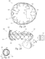
- Figure 1A is a top view of a coaptation assist device 100 (also referred to as a "mitral valve repair device 100" or “device 100") configured in accordance with some embodiments of the present technology
- Figure 1B illustrates a mitral valve repair and monitoring system 101 ("system 101 ") including the device 100 of Figure 1A implanted in a heart in accordance with some embodiments of the present technology.
- the fixation member 102 can include an expandable mesh structure 108 (e.g., a stent) having an oval or circular shape in the deployed state and defining an open central lumen 110 that allows blood to pass therethrough.
- the mesh structure 108 can be a stent made of nitinol or other suitable stent material.
- the fixation member 102 can shaped to conform to the walls of the left atrium ("LA") just above the mitral annulus to secure the device 100 to the supra-annular tissue. After implantation (e.g., 3 days, 2 weeks, 1 month, 2 months), the fixation member 102 or portions thereof become covered by a layer of tissue, and this tissue ingrowth adheres the device 100 permanently to the atrial wall.
- LA left atrium
- the fixation member 102 may also include cleats or other frictional elements to enhance fixation and facilitate tissue ingrowth.
- the fixation member 102 has a semi-circular or other shape that does not extend fully around the circumference of the native valve.
- the fixation member 102 may also or alternatively include one or more portions that press against sub-annular tissue to provide sub-annular device fixation.
- the inductive element may be enhanced or optimized by using a coil with a number of low-resistance wires (e.g., gold wires).
- the coil can be isolated from the external electromagnetic stimulating fields to prevent the stents and struts of the fixation member 102 and/or the coaptation structure 104 from acting as a Faraday cage.
- the desired isolation can be attained by spacing the inductive element (e.g., the coil(s)) apart from a middle or central portion of the fixation member 102, such as at the top (atrial) edge of the fixation member 102 (e.g., along the atrial crown region 120).
- the inductive element can be exposed to and stimulated by the external energy (e.g., an external magnetic field) without interference from the fixation member frame.
- the external device 122 (also referred to as “an external wireless reader device 122" and an “external stimulation-detection device 122”) can communicate with the sensors 106 via an external antenna to interrogate the sensors 106. If the sensors 106 are capacitive sensors that detect pressure using the tank circuit (also referred to as an "LC circuit” or a “resonant circuit”) described above, then the external device 122 can stimulate the circuit via an oscillating external magnetic field at a frequency close to the resonant frequency of the circuit, and the resulting tank circuit resonant frequency can then be detected via the external device 122.
- the tank circuit also referred to as an "LC circuit” or a "resonant circuit”
- the tank circuits could be designed to resonate at significantly different frequencies, which would allow both circuits (and therefore both sensors 106) to be interrogated by the external device 122 simultaneously without interfering with each other.
- the two or more circuits could be interrogated sequentially, alternating between them at predefined intervals (e.g., every 1-50 milliseconds).
- the external stimulation-detection device 122 may be carried by or integrated into a belt worn around the patient's chest, a vest, a removable pad adhered to the patient's skin or clothing, and/or another device that can be positioned close enough to the mitral repair device 100 and transmit energy (e.g., RF waves, ultrasound) to stimulate, interrogate, detect, and/or wirelessly power the sensors 106 of the implanted device 100.
- the external stimulation-detection device 122 may be a separate handheld device that can be used by the patient, a physician, and/or another party involved in the patient's care.
- the external device 122 can also include a wireless communications detector (e.g., an antenna) that communicates with the sensor 106 of the implanted mitral repair device to receive sensor data.
- This sensor data can be stored locally on the external device 122 and/or communicated to a separate device (e.g., a smart phone, a cloud service, another remote system).
- the detector can be part of a device separate from the device that transmits energy to the implanted sensor.
- the information can also or alternatively be communicated to physicians and/or others to remotely track the patient.
- the system 101 can use the tracked data to initiate alarms for the patient (e.g., via a smart phone) and/or others involved in the patient's care based on predetermined threshold parameters associated with cardiac function, overall patient health, and/or device functionality.
- the device 100 can include other types of sensors in addition to or in place of the capacitive sensors 106 described above.
- the device may include a temperature sensor 126 for detecting temperature.
- the temperature sensor 126 can be attached to the exterior or interior of the baffle structure 104, a portion of the fixation member 102, and/or another portion of the mitral repair device 100.
- the temperature sensor 126 can detect temperature and/or data that can be used to determine temperature, and this information can be communicated to the external device 122 (e.g., via an antenna) for real-time monitoring of temperature surrounding the implanted mitral valve repair device 100.
- the device 100 can also or alternatively include other sensors positioned on or integrated therein that detect other parameters associated with cardiac function, other physiological parameters, and/or device functionality.
- the device 200 includes the fixation member 102, the coaptation structure 104, and at least one sensor 206 configured to detect one or more parameters associated with cardiac function and/or device functionality.
- the sensor 206 is a self-contained sensor with more sophisticated electronic circuitry.
- the sensor 206 may be a self-contained pressure sensor integrating both capacitive and inductive elements.
- the self-contained sensor 206 can be attached to an anterior surface of the fixation member 102 via sutures, adhesive, welding, and/or other coupling mechanism to monitor pressure (e.g., LAP).
- the sensor 206 can be affixed to other portions of the fixation member 102 and/or other portions of the device 200 (e.g., the coaptation structure 104).
- the sensor microchip and antenna can be made from biocompatible materials, allowing for long-term implantability. As would be understood to those having skill in the art, such self-contained sensors can have dimensions of approximately 15mm x 2mm x 3.5mm.
- the fixation member 102 can be an expanded stent cut from a 6mm tube with a wall thickness of 0.25mm-0.5mm. As shown in Figure 2C , such dimensions allow sufficient inner cross-sectional area (e.g., 5mm inner diameter) for the sensor 206 to fit inside of the fixation member 102 when compressed to the deployment state (e.g., 18 Fr outer diameter (6mm)).
- the device 200 can include a plurality of self-contained sensors 206 coupled to various portions of the device 200 and/or one or more types of sensors (e.g., an LC circuit pressure sensor, strain gauges, microphones, flow sensors, temperature sensors).
- the system 201 can further includes an element to power the device 200 and a transmitter to send detected data to the external reader device 122.
- the power for this system 201 can come from an inductive coil stimulated by an oscillating external magnetic field. It might alternatively come from an external ultrasonic pressure wave, or from other sources. This external power source may be integrated into the external reader device 122 or a separate external device.
- the device 200 may include a power storage element, such as a capacitor or battery, in addition to or instead of the external power source.
- the device 200 may store power until it has enough energy to measure via the sensor 206 and transmit via the associated antenna for a certain period of time, such as one or more heartbeats.
- the antenna is integrated into the sensor 206.
- the fixation member 102 or the coaptation structure 104 itself may serve as an antenna to improve transmission of the signal to the external reader device 122.
- the senor 206 can include one or more surface acoustic wave (“SAW”) sensors for monitoring pressure monitoring.
- SAW sensors have been shown to be reliable for detecting in vivo pressure measurements.
- the SAW sensors do not require a power source, have long term stability, are small in size, and can communicate wirelessly with external devices positioned near the sensors.
- the SAW sensor can be configured to be independently sensitive to pressure and temperature.
- Figure 3A is a top view a coaptation assist device 300 (“device 300") configured in accordance with some embodiments of the present technology
- Figure 3B illustrates a mitral valve repair and monitoring system 301 (“system 301") including the device 300 of Figure 3A in accordance with some embodiments of the present technology
- the system 301 and the device 300 of Figures 3A and 3B can include various features similar to the features of the systems 101, 201 and the devices 100, 200 described above with respect to Figures 1A-2C .
- the device 300 includes the fixation member 102, the coaptation structure 104, and at least one sensor 306.
- the sensor 306 incudes an accelerometer for measuring device and/or cardiac motion.
- the natural clotting that occurs within the compartment after device implantation eventually causes the free-floating accelerometer 306 to immobilize and maintain a fixed position within the coaptation structure 104.
- the accelerometer 306 can detect such movement to provide an early signal of potential device abnormalities to allow for early intervention before device failure.
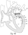
- Figures 4A and 4B illustrate a mitral valve repair and monitoring system 401 (“system 401 ”) including a coaptation assist device 400 (“device 400") shown implanted in a heart during systole and diastole, respectively, in accordance with some embodiments of the present technology.
- the system 401 and the device 400 of Figures 4A and 4B includes various features similar to the features of the systems 101, 201, 301 and the devices 100, 200, 300 described above with respect to Figures 1A-3B .
- the device 400 includes the fixation member 102, the coaptation structure 104, and at least one sensor 406.
- the device 400 further includes an appendage 428 extending from the posterior side of the coaptation structure 104 or the posterior clip 109 and the sensor 406 is carried by the appendage 428.
- the sensor 406 may be an accelerometer that can be used to detect LV wall motion.
- the appendage 428 can include a flexible loop or frame structure 430 (e.g., a nitinol loop or stent structure) that is shaped to be biased outwardly away from the coaptation structure 104 such that the appendage 428 contacts or presses against the LV wall and move with the LV wall throughout the cardiac cycle.
- the loop/frame structure 430 can include a fabric covering 432, such as PET, to promote rapid tissue ingrowth.
- the accelerometer 406 can be attached to the frame structure 430, the covering 432, and/or positioned within the body of the appendage 428 such that it moves with and detects appendage movement imparted by the adjacent ventricular wall. Ventricular wall motion can be used to assess changes in ventricular function.
- the sensor 406 is a strain gauge rather than an accelerometer, or the device 400 includes both an accelerometer and a strain gauge.
- the strain gauge can be affixed to the frame structure 430 and/or other portion of the appendage to detect when the cardiac wall applies force against the appendage 428.
- the sensor 406 can be powered wirelessly by radiofrequency waves and/or other external power source provided (e.g., the external device 122 of Figure 1B ). In other embodiments, sensor 406 can include or be coupled to a power source on the device 400 itself. In some embodiments, the device 400 can include accelerometers, strain gauges on other or additional portions of the device 400 to determine cardiac tissue movement and/or device functionality.
- Figures 5A and 5B are side views of illustrating stages of a procedure for delivering a sensor 506 to an implanted coaptation assist device 500 ("device 500") in accordance with some embodiments of the present technology.
- the device 500 of Figures 5A and 5B includes various features similar to the features of the devices 100, 200, 300, 400 described above with respect to Figures 1A-4B .
- the device 500 includes the fixation member 102, the coaptation structure 104, and at least one sensor 506.
- the sensors may be attached to or integrated with the devices before delivery such that the device and the sensor are delivered as a unit together to the target site proximate to the mitral valve.
- the main body of the device 500 e.g., the fixation member 102 and the coaptation structure 1034 and the sensor 506 can be delivered sequentially.
- the sensor 506 can be delivered sequentially.
- any of the sensor components described above can be deployed after the fixation member 102 and the coaptation structure 104 are already in place in the anatomy.
- lines 538 e.g., sutures
- lines 538 extending from the fixation member 102 back into the delivery system 536 can provide "rails" upon which the sensor 506 be slid and, once properly position with respect to the device 500, locked into place.
- the implant devices described above can be delivered via a trans-femoral approach and/or other approach that passes the devices through the septal wall between chambers of the heart. It can also be delivered via minimally-invasive-surgical trans-apical or trans-atrial approaches, or via open surgical placement.
- a catheter-based delivery could take advantage of various delivery system concepts for implanting heart valve prosthesis and/or cardiac repair devices to target sites proximate to the mitral valve, the aortic valve, the tricuspid valve, and/or other portions of the heart.
Landscapes
- Health & Medical Sciences (AREA)
- Life Sciences & Earth Sciences (AREA)
- Cardiology (AREA)
- Engineering & Computer Science (AREA)
- Biomedical Technology (AREA)
- Veterinary Medicine (AREA)
- Public Health (AREA)
- Heart & Thoracic Surgery (AREA)
- Animal Behavior & Ethology (AREA)
- General Health & Medical Sciences (AREA)
- Physics & Mathematics (AREA)
- Medical Informatics (AREA)
- Surgery (AREA)
- Molecular Biology (AREA)
- Biophysics (AREA)
- Pathology (AREA)
- Vascular Medicine (AREA)
- Transplantation (AREA)
- Oral & Maxillofacial Surgery (AREA)
- Physiology (AREA)
- Hematology (AREA)
- Geometry (AREA)
- Dentistry (AREA)
- Nuclear Medicine, Radiotherapy & Molecular Imaging (AREA)
- Radiology & Medical Imaging (AREA)
- Computer Networks & Wireless Communication (AREA)
- Prostheses (AREA)
Claims (23)
- Un dispositif d'aide à la coaptation (100 ; 200 ; 300 ; 400 ; 500) pour réparer une valve mitrale, le dispositif d'aide à la coaptation (100 ; 200 ; 300 ; 400 ; 500) comprenant :un élément de fixation auriculaire (102) configuré pour appuyer contre le tissu cardiaque à proximité d'un anneau mitral natif ;une structure de coaptation (104) s'étendant à l'opposé de l'élément de fixation auriculaire (102) et radialement vers l'intérieur de l'élément de fixation auriculaire (102) , la structure de coaptation (104) comprenant une surface antérieure (112) configurée pour se coapter avec un premier feuillet natif pendant la systole et une surface postérieure (114) configurée pour déplacer au moins une partie d'un deuxième feuillet natif, la structure de coaptation (104) étant sensiblement stationnaire pendant les cycles cardiaques ; etun capteur (106 ; 206 ; 306 ; 406 ; 506) fixé à une partie du dispositif d'aide à la coaptation (100 ; 200 ; 300 ; 400 ; 500) et configuré pour détecter un ou plusieurs paramètres associés avec au moins une de la fonction cardiaque et la fonctionnalité du dispositif.
- Le dispositif d'aide à la coaptation (100) de la revendication 1, dans lequel :le capteur (106) est un premier capteur de pression (106a) couplé à l'élément de fixation auriculaire (102) et configuré pour détecter la pression auriculaire gauche pendant les cycles cardiaques ; etle dispositif d'aide à la coaptation (100) comprenant en sus un deuxième capteur de pression (106b) couplé à la structure de coaptation (104) et configuré pour détecter la pression ventriculaire gauche pendant les cycles cardiaques.
- Le dispositif d'aide à la coaptation (100) de la revendication 1, dans lequel :le capteur (106) est un premier capteur de pression capacitif (106a) couplé à l'élément de fixation auriculaire (102) et configuré pour détecter la pression auriculaire gauche pendant les cycles cardiaques, le premier capteur de pression capacitif ayant un premier circuit LC avec une première fréquence de résonance ; etle dispositif d'aide à la coaptation (100) comprenant en sus un deuxième capteur de pression capacitif (106b) couplé à la structure de coaptation (104) et configuré pour détecter la pression ventriculaire gauche pendant les cycles cardiaques, le deuxième capteur de pression capacitif (106b) ayant un deuxième circuit LC avec une deuxième fréquence de résonance sensiblement différente de la première fréquence de résonance,les premier et deuxième circuits LC étant configurés pour être interrogés simultanément par un dispositif extérieur (122) sans interférer l'un avec l'autre.
- Le dispositif d'aide à la coaptation (100) d'une quelconque des revendications 1 à 3, dans lequel :l'élément de fixation (102) comprend une structure en treillis métallique (108), au moins une partie de la structure en treillis métallique (108) étant électrolytique ; etle capteur (106) comprend un capteur de pression capacitif attaché à la structure en treillis métallique (108) de l'élément de fixation, la structure en treillis métallique (108) définissant une antenne du capteur de pression capacitif pour transmettre et recevoir des signaux vers et depuis un dispositif extérieur (122).
- Le dispositif d'aide à la coaptation d'une quelconque des revendications 1 à 4, dans lequel :la structure de coaptation (104) comprend une pluralité de montants (116), au moins une partie des montants (116) étant électrolytiques ; etle capteur (106) comprend un capteur de pression capacitif attaché aux montants (116) de la structure de coaptation (104), les montants (116) définissant une antenne du capteur de pression capacitif pour émettre et recevoir des signaux vers et depuis un dispositif extérieur (122).
- Le dispositif d'aide à la coaptation (100) d'une quelconque des revendications 1 à 5, dans lequel :l'élément de fixation (102) comprend une région de bord auriculaire ; etle capteur est un capteur de pression capacitif fixé à la région de bord auriculaire (120), le capteur de pression capacitif (106) comprenant un élément capacitif et un élément inductif, l'élément inductif étant une bobine s'étendant le long de la région de bord auriculaire (120) et configurée pour être stimulée par une source d'énergie extérieure.
- Le dispositif d'aide à la coaptation (100) d'une quelconque des revendications 1 à 6, dans lequel :l'élément de fixation (102) comprend une structure en treillis électrolytique (108) ; etle capteur (106) est un capteur de pression capacitif attaché à l'élément de fixation (102), le capteur de pression capacitif (106) comprenant un élément capacitif et un élément inductif, la structure électrolytique en treillis métallique (108) définissant l'élément inductif.
- Le dispositif d'aide à la coaptation (200) d'une quelconque des revendications 1 à 7, dans lequel le capteur (206) comprend un capteur de pression autonome attaché à une surface antérieure de l'élément de fixation (102).
- Le dispositif d'aide à la coaptation (200) d'une quelconque des revendications 1 à 8, comprenant en sus un élément de stockage d'énergie couplé fonctionnellement au capteur (206) et configuré pour stocker de l'énergie jusqu'à ce que l'élément de stockage d'énergie ait suffisamment d'énergie pour détecter des mesures et transmettre les mesures détectées à un dispositif intérieur (122).
- Le dispositif d'aide à la coaptation (300) d'une quelconque des revendications 1 à 9, dans lequel le capteur (306) comprend un accéléromètre couplé à la structure de coaptation (104) et configuré pour détecter le mouvement de la structure de coaptation (104) pendant les cycles cardiaques.
- Le dispositif d'aide à la coaptation d'une quelconque des revendications 1 à 10, dans lequel la structure de coaptation (104) comprend une pluralité de montants qui définissent une chambre, et dans lequel, avant la distribution du dispositif, le capteur est positionné librement à l'intérieur de la chambre.
- Le dispositif d'aide à la coaptation (400) d'une quelconque des revendications 1 à 11, comprenant en sus :un appendice (428) s'étendant depuis une partie postérieure de la structure de coaptation (104), l'appendice (428) comprenant un cadre flexible (430) sollicité vers l'extérieur de la structure de coaptation (104) et configuré pour entrer en contact avec une paroi ventriculaire gauche ; etdans lequel le capteur (406) comprenant un accéléromètre attaché à l'appendice (428) pour détecter le mouvement de la paroi ventriculaire gauche.
- Le dispositif d'aide à la coaptation (400) d'une quelconque des revendications 1 à 12, dans lequel le capteur (406) comprend au moins un d'un accéléromètre et d'une jauge de contrainte configurés pour détecter le mouvement de la paroi cardiaque.
- Le dispositif d'aide à la coaptation (100) d'une quelconque des revendications 1 à 13, dans lequel le capteur (106) comprend un microphone configuré pour détecter des signaux acoustiques pendant les cycles cardiaques.
- Le dispositif d'aide à la coaptation (100) d'une quelconque des revendications 1 à 14, dans lequel le capteur (106) comprend au moins un capteur de flux couplé à une surface faisant face à l'oreillette de la structure de coaptation (104) et configuré pour mesurer les schémas de flux tout au long des cycles cardiaques.
- Un système de réparation et de surveillance de valve cardiaque (101 ; 201 ; 301 ; 401), comprenant :un dispositif de réparation de valve (100 ; 200 ; 300 ; 400 ; 500) comprenantune structure de coaptation (104) comprenant une surface antérieure configurée pour se coapter avec un premier feuillet natif pendant la systole et une surface postérieure configurée pour déplacer au moins une partie d'un deuxième feuillet natif ; etun élément de fixation (102) couplé à la structure de coaptation (104) et configuré pour ancrer la structure de coaptation(104) à proximité d'un anneau de valve cardiaque natif, la structure de coaptation (104) restant sensiblement stationnaire relativement à l'élément de fixation pendant les cycles cardiaques ; etun capteur de pression (106) configuré pour détecter la pression pendant les cycles cardiaques ; etun dispositif extérieur de stimulation-détection (122) configuré pour interroger le capteur de pression pour recevoir sans fil les données détectées.
- Le système de réparation et de surveillance de valve cardiaque (101 ; 201 ; 301 ; 401) de la revendication 16, dans lequel le dispositif extérieur de stimulation-détection (122) est configuré pour alimenter en puissance le capteur de pression (106).
- Le système de réparation et de surveillance de valve cardiaque des revendications 16 ou 17 (101), dans lequel :le capteur de pression (106) est un premier capteur de pression capacitif (106a) couplé à l'élément de fixation (102) et configuré pour détecter la pression auriculaire gauche pendant les cycles cardiaques, le premier capteur de pression capacitif (106a) ayant un premier circuit LC avec une première fréquence de résonance ; etle dispositif de réparation de valve (100) comprend en sus un deuxième capteur de pression capacitif (106b) couplé à la structure de coaptation (104) et configuré pour détecter la pression ventriculaire gauche pendant les cycles cardiaques, le deuxième capteur de pression capacitif (106b) ayant un deuxième circuit LC avec une deuxième fréquence de résonance sensiblement différente de la première fréquence de résonance,les premier et deuxième circuits LC étant configurés pour être interrogés simultanément par un dispositif extérieur (122) sans interférer l'un avec l'autre.
- Le système de réparation et de surveillance de valve cardiaque (101) de la revendication 18, dans lequel :le premier capteur de pression capacitif (106a) comprend un premier circuit LC avec une première fréquence de résonance ;le deuxième capteur de pression capacitif (106b) comprend un deuxième circuit LC avec une deuxième fréquence de résonance sensiblement différente de la première fréquence de résonance,le dispositif extérieur de stimulation-détection étant configuré pour interroger simultanément les premier et deuxième circuits LC.
- Le système de réparation et de surveillance de valve cardiaque d'une quelconque des revendications 16 à 19, comprenant en sus :
un système de distribution (536) configuré pour délivrer le capteur (106) à l'élément de fixation (102) après le déploiement de l'élément de fixation (102). - Le système de réparation et de surveillance de valve cardiaque (101) d'une quelconque des revendications 16 à 20, dans lequel :l'élément de fixation (102) comprend une structure en treillis métallique ;la structure de coaptation (104) comprend une pluralité de montants (116) ; etau moins une de la structure en treillis métallique et la pluralité de montants définit une antenne pour le capteur de pression (106) pour communiquer avec le dispositif extérieur de stimulation-détection (122).
- Le système de réparation et de surveillance de valve cardiaque (301) d'une quelconque des revendications 16 à 21, comprenant en sus un accéléromètre (306) couplé à la structure de coaptation (104) et configuré pour détecter le mouvement de la structure de coaptation (104) pendant les cycles cardiaques.
- Le système de réparation et de surveillance de valve cardiaque d'une quelconque des revendications 16 à 22, dans lequel le dispositif de réparation de valve (400) comprend :un appendice (428) s'étendant depuis une partie postérieure de la structure de coaptation (104), l'appendice (428) étant sollicité vers l'extérieur pour s'éloigner de la structure de coaptation (104) et configuré pour entrer en contact avec une paroi ventriculaire ; etun accéléromètre (406) attaché à l'appendice (428) pour détecter le mouvement de la paroi ventriculaire pendant les cycles cardiaques.
Applications Claiming Priority (2)
| Application Number | Priority Date | Filing Date | Title |
|---|---|---|---|
| US201962793273P | 2019-01-16 | 2019-01-16 | |
| PCT/US2020/013953 WO2020150526A1 (fr) | 2019-01-16 | 2020-01-16 | Dispositifs d'aide à la coaptation implantables avec capteurs et systèmes et procédés associés |
Publications (2)
| Publication Number | Publication Date |
|---|---|
| EP3911273A1 EP3911273A1 (fr) | 2021-11-24 |
| EP3911273B1 true EP3911273B1 (fr) | 2025-01-15 |
Family
ID=69591741
Family Applications (1)
| Application Number | Title | Priority Date | Filing Date |
|---|---|---|---|
| EP20705565.8A Active EP3911273B1 (fr) | 2019-01-16 | 2020-01-16 | Dispositifs d'aide à la coaptation implantables avec capteurs et systèmes |
Country Status (5)
| Country | Link |
|---|---|
| US (2) | US11633281B2 (fr) |
| EP (1) | EP3911273B1 (fr) |
| JP (2) | JP2022518028A (fr) |
| CN (1) | CN114502101A (fr) |
| WO (1) | WO2020150526A1 (fr) |
Families Citing this family (36)
| Publication number | Priority date | Publication date | Assignee | Title |
|---|---|---|---|---|
| US8845717B2 (en) | 2011-01-28 | 2014-09-30 | Middle Park Medical, Inc. | Coaptation enhancement implant, system, and method |
| US8888843B2 (en) | 2011-01-28 | 2014-11-18 | Middle Peak Medical, Inc. | Device, system, and method for transcatheter treatment of valve regurgitation |
| US10166098B2 (en) | 2013-10-25 | 2019-01-01 | Middle Peak Medical, Inc. | Systems and methods for transcatheter treatment of valve regurgitation |
| EP3157469B2 (fr) | 2014-06-18 | 2024-10-02 | Polares Medical Inc. | Implants de valvule mitrale pour le traitement de la régurgitation valvulaire |
| ES2914153T3 (es) | 2014-06-24 | 2022-06-07 | Polares Medical Inc | Sistemas para anclar un implante |
| US9592121B1 (en) | 2015-11-06 | 2017-03-14 | Middle Peak Medical, Inc. | Device, system, and method for transcatheter treatment of valvular regurgitation |
| CN114587711A (zh) | 2017-03-13 | 2022-06-07 | 宝来瑞斯医疗有限公司 | 用于经导管治疗瓣膜返流的装置、系统和方法 |
| US10478303B2 (en) | 2017-03-13 | 2019-11-19 | Polares Medical Inc. | Device, system, and method for transcatheter treatment of valvular regurgitation |
| US10653524B2 (en) | 2017-03-13 | 2020-05-19 | Polares Medical Inc. | Device, system, and method for transcatheter treatment of valvular regurgitation |
| JP7134229B2 (ja) | 2017-07-06 | 2022-09-09 | ラグビア バスデ, | 組織把持デバイスおよび関連方法 |
| EP4413955A3 (fr) | 2017-07-24 | 2024-11-13 | Emory University | Dispositifs d'amélioration de feuillet de valvule cardiaque |
| US11083572B2 (en) | 2017-08-31 | 2021-08-10 | Half Moon Medical, Inc. | Prosthetic leaflet device |
| WO2020150526A1 (fr) | 2019-01-16 | 2020-07-23 | Kappetein Arie Pieter | Dispositifs d'aide à la coaptation implantables avec capteurs et systèmes et procédés associés |
| US11504237B2 (en) | 2019-03-12 | 2022-11-22 | Half Moon Medical, Inc. | Cardiac valve repair devices with annuloplasty features and associated systems and methods |
| EP3972534A4 (fr) | 2019-05-22 | 2023-08-02 | Triflo Cardiovascular Inc. | Dispositif de support de valvule cardiaque |
| EP4007546B1 (fr) | 2019-09-19 | 2026-04-22 | Medtronic, Inc. | Dispositifs de réparation de valvule comprenant des structures de coaptation et de multiples pinces de capture de feuillet |
| EP4210560A4 (fr) * | 2020-09-04 | 2024-10-23 | Northwestern University | Systèmes de capteurs passifs sans fil basés sur lcr pour déploiement implantable utilisant une électromécanique pliable et applications de ceux-ci |
| CN116710029A (zh) | 2020-11-20 | 2023-09-05 | 半月医疗有限公司 | 三尖瓣修复装置及相关系统和方法 |
| US11464634B2 (en) | 2020-12-16 | 2022-10-11 | Polares Medical Inc. | Device, system, and method for transcatheter treatment of valvular regurgitation with secondary anchors |
| WO2022177853A1 (fr) * | 2021-02-18 | 2022-08-25 | Shlomo Gabbay | Dispositif de réparation automatique injectable ou percutané et son procédé d'insertion |
| US11759321B2 (en) | 2021-06-25 | 2023-09-19 | Polares Medical Inc. | Device, system, and method for transcatheter treatment of valvular regurgitation |
| CN115804672B (zh) * | 2021-09-14 | 2026-03-13 | 浙江宏海医疗器械有限公司 | 一种人工心脏瓣膜支架 |
| CN115804669B (zh) * | 2021-09-14 | 2025-08-22 | 浙江宏海医疗器械有限公司 | 一种编织支架的制作方法和编织支架 |
| WO2023097337A2 (fr) * | 2021-11-29 | 2023-06-01 | Alan Ostroff | Capteur implantable actif |
| EP4193962A1 (fr) * | 2021-12-07 | 2023-06-14 | AVVie GmbH | Implant pour améliorer la coaptation d'une valve atrioventriculaire |
| CN116763502A (zh) * | 2022-03-11 | 2023-09-19 | 上海臻亿医疗科技有限公司 | 一种人工心脏瓣膜 |
| CN115581542A (zh) * | 2022-09-23 | 2023-01-10 | 浙江智柔科技有限公司 | 用于瓣膜压差测量的压力传感器及可植入心脏瓣膜 |
| CN117982262B (zh) * | 2022-10-27 | 2025-07-25 | 合源医疗器械(上海)有限公司 | 心脏植入物 |
| CN115886758A (zh) * | 2022-11-24 | 2023-04-04 | 深圳北芯生命科技股份有限公司 | 瓣膜闭合辨别装置、系统及存储介质 |
| CN116269276A (zh) * | 2023-04-06 | 2023-06-23 | 微创投资控股有限公司 | 植入式传感器及传感器系统 |
| US12478474B2 (en) | 2023-05-04 | 2025-11-25 | Polares Medical Inc. | Device, system, and method with an adaptive leaflet |
| CN119326565A (zh) * | 2023-07-21 | 2025-01-21 | 合源医疗器械(上海)有限公司 | 植入物及植入物系统 |
| US12433749B2 (en) | 2023-08-25 | 2025-10-07 | Emory University | Systems, devices, and methods for reducing heart valve regurgitation |
| US12514705B2 (en) * | 2024-05-29 | 2026-01-06 | Vesalius Cardiovascular Inc. | Heart valve repair apparatus |
| US12396855B1 (en) | 2024-07-25 | 2025-08-26 | Nyra Medical, Inc. | Systems, devices, and methods for reducing heart valve regurgitation |
| US12605553B1 (en) | 2025-02-19 | 2026-04-21 | Smartvalves Ltd | In situ assembly of prosthetic pacing valves |
Citations (2)
| Publication number | Priority date | Publication date | Assignee | Title |
|---|---|---|---|---|
| US20160045316A1 (en) * | 2014-08-18 | 2016-02-18 | St. Jude Medical, Cardiology Division, Inc. | Prosthetic heart devices having diagnostic capabilities |
| WO2018204335A1 (fr) * | 2017-05-01 | 2018-11-08 | The Cleveland Clinic Foundation | Systèmes et procédés de traitement d'une valve cardiaque régurgitante |
Family Cites Families (69)
| Publication number | Priority date | Publication date | Assignee | Title |
|---|---|---|---|---|
| DE19746735C2 (de) * | 1997-10-13 | 2003-11-06 | Simag Gmbh Systeme Und Instr F | NMR-Bildgebungsverfahren zur Darstellung, Positionsbestimmung oder funktionellen Kontrolle einer in ein Untersuchungsobjekt eingeführten Vorrichtung und Vorrichtung zur Verwendung in einem derartigen Verfahren |
| US7018406B2 (en) | 1999-11-17 | 2006-03-28 | Corevalve Sa | Prosthetic valve for transluminal delivery |
| US6869444B2 (en) * | 2000-05-22 | 2005-03-22 | Shlomo Gabbay | Low invasive implantable cardiac prosthesis and method for helping improve operation of a heart valve |
| US6855115B2 (en) * | 2002-01-22 | 2005-02-15 | Cardiomems, Inc. | Implantable wireless sensor for pressure measurement within the heart |
| US8052751B2 (en) | 2003-07-02 | 2011-11-08 | Flexcor, Inc. | Annuloplasty rings for repairing cardiac valves |
| US7160322B2 (en) | 2003-08-13 | 2007-01-09 | Shlomo Gabbay | Implantable cardiac prosthesis for mitigating prolapse of a heart valve |
| CA2536192A1 (fr) * | 2003-11-20 | 2005-06-09 | Angiotech International Ag | Implants pour tissus mous et agents anti-cicatrices |
| US8012202B2 (en) | 2004-07-27 | 2011-09-06 | Alameddine Abdallah K | Mitral valve ring for treatment of mitral valve regurgitation |
| US10390714B2 (en) * | 2005-01-12 | 2019-08-27 | Remon Medical Technologies, Ltd. | Devices for fixing a sensor in a lumen |
| EP1919400A1 (fr) | 2005-08-12 | 2008-05-14 | Edwards Lifesciences Corporation | Implant médical comportant un mécanisme de renfort |
| US8430926B2 (en) | 2006-08-11 | 2013-04-30 | Japd Consulting Inc. | Annuloplasty with enhanced anchoring to the annulus based on tissue healing |
| US8545553B2 (en) | 2009-05-04 | 2013-10-01 | Valtech Cardio, Ltd. | Over-wire rotation tool |
| US20100217382A1 (en) | 2009-02-25 | 2010-08-26 | Edwards Lifesciences | Mitral valve replacement with atrial anchoring |
| US20100262233A1 (en) | 2009-04-12 | 2010-10-14 | Texas Tech University System | Mitral Valve Coaptation Plate For Mitral Valve Regurgitation |
| US8821570B2 (en) | 2009-07-20 | 2014-09-02 | Micardia Corporation | Adjustable annuloplasty ring with subcutaneous activation port |
| US8845722B2 (en) | 2009-08-03 | 2014-09-30 | Shlomo Gabbay | Heart valve prosthesis and method of implantation thereof |
| US8845717B2 (en) | 2011-01-28 | 2014-09-30 | Middle Park Medical, Inc. | Coaptation enhancement implant, system, and method |
| US8888843B2 (en) | 2011-01-28 | 2014-11-18 | Middle Peak Medical, Inc. | Device, system, and method for transcatheter treatment of valve regurgitation |
| WO2012175483A1 (fr) | 2011-06-20 | 2012-12-27 | Jacques Seguin | Ensemble de prothèses valvaires pour réparer une valvule cardiaque défectueuse et ses procédés d'utilisation |
| CA2840084C (fr) | 2011-06-21 | 2019-11-05 | Foundry Newco Xii, Inc. | Dispositifs de valvule cardiaque prosthetiques et systemes et procedes associes |
| US9364326B2 (en) | 2011-06-29 | 2016-06-14 | Mitralix Ltd. | Heart valve repair devices and methods |
| US10799360B2 (en) * | 2011-07-27 | 2020-10-13 | The Cleveland Clinic Foundation | Systems and methods for treating a regurgitant heart valve |
| WO2013021374A2 (fr) * | 2011-08-05 | 2013-02-14 | Mitraltech Ltd. | Techniques pour le remplacement et la fixation percutanés d'une valvule mitrale |
| US9549817B2 (en) | 2011-09-22 | 2017-01-24 | Transmural Systems Llc | Devices, systems and methods for repairing lumenal systems |
| WO2015020971A1 (fr) * | 2013-08-04 | 2015-02-12 | Mehr Medical Llc | Dispositifs, systèmes et procédés de réparation de systèmes de lumen |
| WO2013131069A1 (fr) | 2012-03-02 | 2013-09-06 | Mehr Medical Llc | Prothèses |
| EP2819618B1 (fr) | 2012-02-28 | 2018-05-02 | Mvalve Technologies Ltd. | Support de valvule cardiaque à anneau unique |
| CN104684505B (zh) * | 2012-05-20 | 2017-07-07 | 戴尔马修墨医学研究内结构和服务有限公司 | 人造二尖瓣 |
| US9510946B2 (en) | 2012-09-06 | 2016-12-06 | Edwards Lifesciences Corporation | Heart valve sealing devices |
| CN105377192A (zh) | 2013-05-09 | 2016-03-02 | 米塔埃瑟斯医疗有限公司 | 心脏瓣膜辅助修复体 |
| EP3326583B1 (fr) | 2013-05-20 | 2018-12-12 | Edwards Lifesciences Corporation | Appareil de pose de valvule cardiaque prothétique |
| FR3006582B1 (fr) | 2013-06-05 | 2015-07-17 | Mustapha Ladjali | Dispositif de traitement d'un tissu corporel et necessaire de traitement associe |
| CN105451688A (zh) | 2013-06-14 | 2016-03-30 | 哈祖有限公司 | 用于治疗瓣膜反流的方法和装置 |
| US20160030176A1 (en) * | 2014-08-04 | 2016-02-04 | Medizinische Universität Wien | Implant and method for improving coaptation of an atrioventricular valve |
| WO2015052570A1 (fr) | 2013-10-07 | 2015-04-16 | Medizinische Universität Wien | Implant et procédé pour améliorer la coaptation d'une valve atrioventriculaire |
| US10166098B2 (en) * | 2013-10-25 | 2019-01-01 | Middle Peak Medical, Inc. | Systems and methods for transcatheter treatment of valve regurgitation |
| US9889004B2 (en) | 2013-11-19 | 2018-02-13 | St. Jude Medical, Cardiology Division, Inc. | Sealing structures for paravalvular leak protection |
| EP3073964B1 (fr) | 2013-11-27 | 2024-12-18 | St. Jude Medical, Cardiology Division, Inc. | Piqûres de renfort de ballonnet |
| US9913717B2 (en) | 2014-02-14 | 2018-03-13 | Edwards Lifesciences Corporation | Percutaneous leaflet augmentation |
| EP4706597A2 (fr) | 2014-05-16 | 2026-03-11 | St. Jude Medical, Cardiology Division, Inc. | Ensemble stent destiné à être utilisé dans des valvules cardiaques prothétiques |
| EP3157469B2 (fr) | 2014-06-18 | 2024-10-02 | Polares Medical Inc. | Implants de valvule mitrale pour le traitement de la régurgitation valvulaire |
| CN104055605B (zh) | 2014-07-07 | 2016-06-01 | 宁波健世生物科技有限公司 | 一种用于阻止瓣膜反流的假体 |
| EP3182930B1 (fr) * | 2014-08-18 | 2020-09-23 | St. Jude Medical, Cardiology Division, Inc. | Capteurs pour dispositifs prosthétiques cardiaques |
| JP6451484B2 (ja) | 2015-05-11 | 2019-01-16 | 株式会社デンソー | 熱流束センサの製造方法およびそれに用いる熱流発生装置 |
| US10531956B2 (en) | 2015-09-03 | 2020-01-14 | Vesalous Cardiovascular Inc. | Apparatus for repairing heart valves and method of use thereof |
| US10022223B2 (en) | 2015-10-06 | 2018-07-17 | W. L. Gore & Associates, Inc. | Leaflet support devices and methods of making and using the same |
| US9592121B1 (en) | 2015-11-06 | 2017-03-14 | Middle Peak Medical, Inc. | Device, system, and method for transcatheter treatment of valvular regurgitation |
| EP3632380B1 (fr) | 2015-12-03 | 2024-01-24 | Tendyne Holdings, Inc. | Attributs de cadre pour valvules mitrales prothétiques |
| EP3389566B1 (fr) | 2015-12-14 | 2024-05-08 | Medtronic Vascular, Inc. | Dispositifs pour pose et chargement de valvule cardiaque transcathéter |
| US10667904B2 (en) * | 2016-03-08 | 2020-06-02 | Edwards Lifesciences Corporation | Valve implant with integrated sensor and transmitter |
| EP3426195A4 (fr) | 2016-03-08 | 2019-11-20 | Dura LLC | Système de remplacement de lame valvulaire et méthode associée |
| EP3435929B1 (fr) | 2016-03-29 | 2020-05-20 | Cardinal Health Switzerland 515 GmbH | Endoprothèse à entretoises biorésorbables capable de se contracter |
| WO2017180134A1 (fr) | 2016-04-14 | 2017-10-19 | Lockheed Martin Corporation | Procédés pour l'utilisation in vivo et in vitro de graphène et d'autres matériaux bidimensionnels |
| US20170360558A1 (en) | 2016-06-16 | 2017-12-21 | Jianlu Ma | Method and design for a mitral regurgitation treatment device |
| US10215632B2 (en) | 2016-09-19 | 2019-02-26 | Zycor Labs Inc. | Method and apparatus for spectral reflectance imaging using digital cameras |
| WO2018142186A1 (fr) * | 2017-02-01 | 2018-08-09 | Tre Esse Progettazione Biomedica S.R.L. | Capteur de fonction cardiaque et dispositif d'implant correspondant |
| EP3372198B1 (fr) | 2017-03-06 | 2019-06-19 | AVVie GmbH | Implant pour améliorer la coaptation d'une valve atrioventriculaire |
| US10478303B2 (en) | 2017-03-13 | 2019-11-19 | Polares Medical Inc. | Device, system, and method for transcatheter treatment of valvular regurgitation |
| CN114587711A (zh) | 2017-03-13 | 2022-06-07 | 宝来瑞斯医疗有限公司 | 用于经导管治疗瓣膜返流的装置、系统和方法 |
| EP4413955A3 (fr) | 2017-07-24 | 2024-11-13 | Emory University | Dispositifs d'amélioration de feuillet de valvule cardiaque |
| US11083572B2 (en) * | 2017-08-31 | 2021-08-10 | Half Moon Medical, Inc. | Prosthetic leaflet device |
| JP7438212B2 (ja) | 2018-11-14 | 2024-02-26 | ハーフ ムーン メディカル インコーポレイテッド | 心臓弁尖用の尖延長器具 |
| US11452601B2 (en) | 2018-12-13 | 2022-09-27 | Medtronic Vascular, Inc. | Wire annuloplasty ring |
| WO2020150526A1 (fr) | 2019-01-16 | 2020-07-23 | Kappetein Arie Pieter | Dispositifs d'aide à la coaptation implantables avec capteurs et systèmes et procédés associés |
| US11504237B2 (en) * | 2019-03-12 | 2022-11-22 | Half Moon Medical, Inc. | Cardiac valve repair devices with annuloplasty features and associated systems and methods |
| EP4014894A4 (fr) | 2019-08-13 | 2022-08-31 | Hangzhou Valgen Medtech Co., Ltd. | Dispositif de serrage de valve réglable et système de serrage de valve |
| EP4007546B1 (fr) * | 2019-09-19 | 2026-04-22 | Medtronic, Inc. | Dispositifs de réparation de valvule comprenant des structures de coaptation et de multiples pinces de capture de feuillet |
| CA3143389A1 (fr) * | 2019-12-06 | 2021-06-10 | Edwards Lifesciences Corporation | Ensemble et systeme de surveillance de valve cardiaque prothetique |
| US12588996B2 (en) * | 2020-11-20 | 2026-03-31 | Medtronic, Inc. | Cardiac valve repair devices and associated systems and methods |
-
2020
- 2020-01-16 WO PCT/US2020/013953 patent/WO2020150526A1/fr not_active Ceased
- 2020-01-16 EP EP20705565.8A patent/EP3911273B1/fr active Active
- 2020-01-16 US US16/745,246 patent/US11633281B2/en active Active
- 2020-01-16 JP JP2021541298A patent/JP2022518028A/ja active Pending
- 2020-01-16 CN CN202080021943.6A patent/CN114502101A/zh active Pending
-
2023
- 2023-03-21 US US18/187,603 patent/US12390331B2/en active Active
-
2024
- 2024-09-30 JP JP2024170520A patent/JP2025013794A/ja active Pending
Patent Citations (2)
| Publication number | Priority date | Publication date | Assignee | Title |
|---|---|---|---|---|
| US20160045316A1 (en) * | 2014-08-18 | 2016-02-18 | St. Jude Medical, Cardiology Division, Inc. | Prosthetic heart devices having diagnostic capabilities |
| WO2018204335A1 (fr) * | 2017-05-01 | 2018-11-08 | The Cleveland Clinic Foundation | Systèmes et procédés de traitement d'une valve cardiaque régurgitante |
Also Published As
| Publication number | Publication date |
|---|---|
| JP2022518028A (ja) | 2022-03-11 |
| JP2025013794A (ja) | 2025-01-28 |
| WO2020150526A1 (fr) | 2020-07-23 |
| US12390331B2 (en) | 2025-08-19 |
| EP3911273A1 (fr) | 2021-11-24 |
| US11633281B2 (en) | 2023-04-25 |
| US20200222185A1 (en) | 2020-07-16 |
| US20230329865A1 (en) | 2023-10-19 |
| CN114502101A (zh) | 2022-05-13 |
Similar Documents
| Publication | Publication Date | Title |
|---|---|---|
| US12390331B2 (en) | Implantable coaptation assist devices with sensors and associated systems and methods | |
| US20260033946A1 (en) | Valve implant with integrated sensor and transmitter | |
| JP7719234B2 (ja) | 直接的心臓圧力監視 | |
| US20210401418A1 (en) | Occluder with self-powered sensors | |
| EP3182927B1 (fr) | Dispositifs cardiaques prothétiques ayant des capacités de diagnostic | |
| US20230218180A1 (en) | Monitoring systems and devices for heart implants | |
| CN113395931A (zh) | 集成压力感测的心脏植入装置 | |
| US20100217136A1 (en) | Medical devices | |
| US20050165317A1 (en) | Medical devices | |
| US20250281123A1 (en) | Transcatheter heart valve with deformable inductor for dual wireless pressure monitoring | |
| US20250352335A1 (en) | Antennae for stent and heart valves |
Legal Events
| Date | Code | Title | Description |
|---|---|---|---|
| STAA | Information on the status of an ep patent application or granted ep patent |
Free format text: STATUS: UNKNOWN |
|
| STAA | Information on the status of an ep patent application or granted ep patent |
Free format text: STATUS: THE INTERNATIONAL PUBLICATION HAS BEEN MADE |
|
| PUAI | Public reference made under article 153(3) epc to a published international application that has entered the european phase |
Free format text: ORIGINAL CODE: 0009012 |
|
| STAA | Information on the status of an ep patent application or granted ep patent |
Free format text: STATUS: REQUEST FOR EXAMINATION WAS MADE |
|
| 17P | Request for examination filed |
Effective date: 20210715 |
|
| AK | Designated contracting states |
Kind code of ref document: A1 Designated state(s): AL AT BE BG CH CY CZ DE DK EE ES FI FR GB GR HR HU IE IS IT LI LT LU LV MC MK MT NL NO PL PT RO RS SE SI SK SM TR |
|
| DAV | Request for validation of the european patent (deleted) | ||
| DAX | Request for extension of the european patent (deleted) | ||
| GRAP | Despatch of communication of intention to grant a patent |
Free format text: ORIGINAL CODE: EPIDOSNIGR1 |
|
| STAA | Information on the status of an ep patent application or granted ep patent |
Free format text: STATUS: GRANT OF PATENT IS INTENDED |
|
| INTG | Intention to grant announced |
Effective date: 20240805 |
|
| GRAS | Grant fee paid |
Free format text: ORIGINAL CODE: EPIDOSNIGR3 |
|
| GRAA | (expected) grant |
Free format text: ORIGINAL CODE: 0009210 |
|
| STAA | Information on the status of an ep patent application or granted ep patent |
Free format text: STATUS: THE PATENT HAS BEEN GRANTED |
|
| P01 | Opt-out of the competence of the unified patent court (upc) registered |
Free format text: CASE NUMBER: APP_61567/2024 Effective date: 20241118 |
|
| AK | Designated contracting states |
Kind code of ref document: B1 Designated state(s): AL AT BE BG CH CY CZ DE DK EE ES FI FR GB GR HR HU IE IS IT LI LT LU LV MC MK MT NL NO PL PT RO RS SE SI SK SM TR |
|
| REG | Reference to a national code |
Ref country code: CH Ref legal event code: EP Ref country code: GB Ref legal event code: FG4D |
|
| REG | Reference to a national code |
Ref country code: DE Ref legal event code: R096 Ref document number: 602020044760 Country of ref document: DE |
|
| REG | Reference to a national code |
Ref country code: IE Ref legal event code: FG4D |
|
| REG | Reference to a national code |
Ref country code: NL Ref legal event code: MP Effective date: 20250115 |
|
| PG25 | Lapsed in a contracting state [announced via postgrant information from national office to epo] |
Ref country code: NL Free format text: LAPSE BECAUSE OF FAILURE TO SUBMIT A TRANSLATION OF THE DESCRIPTION OR TO PAY THE FEE WITHIN THE PRESCRIBED TIME-LIMIT Effective date: 20250115 |
|
| PG25 | Lapsed in a contracting state [announced via postgrant information from national office to epo] |
Ref country code: RS Free format text: LAPSE BECAUSE OF FAILURE TO SUBMIT A TRANSLATION OF THE DESCRIPTION OR TO PAY THE FEE WITHIN THE PRESCRIBED TIME-LIMIT Effective date: 20250415 |
|
| PG25 | Lapsed in a contracting state [announced via postgrant information from national office to epo] |
Ref country code: FI Free format text: LAPSE BECAUSE OF FAILURE TO SUBMIT A TRANSLATION OF THE DESCRIPTION OR TO PAY THE FEE WITHIN THE PRESCRIBED TIME-LIMIT Effective date: 20250115 |
|
| PG25 | Lapsed in a contracting state [announced via postgrant information from national office to epo] |
Ref country code: PL Free format text: LAPSE BECAUSE OF FAILURE TO SUBMIT A TRANSLATION OF THE DESCRIPTION OR TO PAY THE FEE WITHIN THE PRESCRIBED TIME-LIMIT Effective date: 20250115 |
|
| PG25 | Lapsed in a contracting state [announced via postgrant information from national office to epo] |
Ref country code: ES Free format text: LAPSE BECAUSE OF FAILURE TO SUBMIT A TRANSLATION OF THE DESCRIPTION OR TO PAY THE FEE WITHIN THE PRESCRIBED TIME-LIMIT Effective date: 20250115 |
|
| REG | Reference to a national code |
Ref country code: LT Ref legal event code: MG9D |
|
| PG25 | Lapsed in a contracting state [announced via postgrant information from national office to epo] |
Ref country code: IS Free format text: LAPSE BECAUSE OF FAILURE TO SUBMIT A TRANSLATION OF THE DESCRIPTION OR TO PAY THE FEE WITHIN THE PRESCRIBED TIME-LIMIT Effective date: 20250515 Ref country code: NO Free format text: LAPSE BECAUSE OF FAILURE TO SUBMIT A TRANSLATION OF THE DESCRIPTION OR TO PAY THE FEE WITHIN THE PRESCRIBED TIME-LIMIT Effective date: 20250415 |
|
| REG | Reference to a national code |
Ref country code: AT Ref legal event code: MK05 Ref document number: 1759366 Country of ref document: AT Kind code of ref document: T Effective date: 20250115 |
|
| PG25 | Lapsed in a contracting state [announced via postgrant information from national office to epo] |
Ref country code: HR Free format text: LAPSE BECAUSE OF FAILURE TO SUBMIT A TRANSLATION OF THE DESCRIPTION OR TO PAY THE FEE WITHIN THE PRESCRIBED TIME-LIMIT Effective date: 20250115 |
|
| PG25 | Lapsed in a contracting state [announced via postgrant information from national office to epo] |
Ref country code: LV Free format text: LAPSE BECAUSE OF FAILURE TO SUBMIT A TRANSLATION OF THE DESCRIPTION OR TO PAY THE FEE WITHIN THE PRESCRIBED TIME-LIMIT Effective date: 20250115 Ref country code: PT Free format text: LAPSE BECAUSE OF FAILURE TO SUBMIT A TRANSLATION OF THE DESCRIPTION OR TO PAY THE FEE WITHIN THE PRESCRIBED TIME-LIMIT Effective date: 20250515 |
|
| PG25 | Lapsed in a contracting state [announced via postgrant information from national office to epo] |
Ref country code: GR Free format text: LAPSE BECAUSE OF FAILURE TO SUBMIT A TRANSLATION OF THE DESCRIPTION OR TO PAY THE FEE WITHIN THE PRESCRIBED TIME-LIMIT Effective date: 20250416 Ref country code: BG Free format text: LAPSE BECAUSE OF FAILURE TO SUBMIT A TRANSLATION OF THE DESCRIPTION OR TO PAY THE FEE WITHIN THE PRESCRIBED TIME-LIMIT Effective date: 20250115 |
|
| PG25 | Lapsed in a contracting state [announced via postgrant information from national office to epo] |
Ref country code: AT Free format text: LAPSE BECAUSE OF FAILURE TO SUBMIT A TRANSLATION OF THE DESCRIPTION OR TO PAY THE FEE WITHIN THE PRESCRIBED TIME-LIMIT Effective date: 20250115 |
|
| REG | Reference to a national code |
Ref country code: CH Ref legal event code: PL |
|
| PG25 | Lapsed in a contracting state [announced via postgrant information from national office to epo] |
Ref country code: SE Free format text: LAPSE BECAUSE OF FAILURE TO SUBMIT A TRANSLATION OF THE DESCRIPTION OR TO PAY THE FEE WITHIN THE PRESCRIBED TIME-LIMIT Effective date: 20250115 |
|
| PG25 | Lapsed in a contracting state [announced via postgrant information from national office to epo] |
Ref country code: LU Free format text: LAPSE BECAUSE OF NON-PAYMENT OF DUE FEES Effective date: 20250116 |
|
| PG25 | Lapsed in a contracting state [announced via postgrant information from national office to epo] |
Ref country code: SM Free format text: LAPSE BECAUSE OF FAILURE TO SUBMIT A TRANSLATION OF THE DESCRIPTION OR TO PAY THE FEE WITHIN THE PRESCRIBED TIME-LIMIT Effective date: 20250115 |
|
| PG25 | Lapsed in a contracting state [announced via postgrant information from national office to epo] |
Ref country code: DK Free format text: LAPSE BECAUSE OF FAILURE TO SUBMIT A TRANSLATION OF THE DESCRIPTION OR TO PAY THE FEE WITHIN THE PRESCRIBED TIME-LIMIT Effective date: 20250115 |
|
| PG25 | Lapsed in a contracting state [announced via postgrant information from national office to epo] |
Ref country code: MC Free format text: LAPSE BECAUSE OF FAILURE TO SUBMIT A TRANSLATION OF THE DESCRIPTION OR TO PAY THE FEE WITHIN THE PRESCRIBED TIME-LIMIT Effective date: 20250115 |
|
| PG25 | Lapsed in a contracting state [announced via postgrant information from national office to epo] |
Ref country code: IT Free format text: LAPSE BECAUSE OF FAILURE TO SUBMIT A TRANSLATION OF THE DESCRIPTION OR TO PAY THE FEE WITHIN THE PRESCRIBED TIME-LIMIT Effective date: 20250115 |
|
| PG25 | Lapsed in a contracting state [announced via postgrant information from national office to epo] |
Ref country code: BE Free format text: LAPSE BECAUSE OF NON-PAYMENT OF DUE FEES Effective date: 20250131 |
|
| REG | Reference to a national code |
Ref country code: DE Ref legal event code: R097 Ref document number: 602020044760 Country of ref document: DE |
|
| PG25 | Lapsed in a contracting state [announced via postgrant information from national office to epo] |
Ref country code: CH Free format text: LAPSE BECAUSE OF NON-PAYMENT OF DUE FEES Effective date: 20250131 |
|
| PG25 | Lapsed in a contracting state [announced via postgrant information from national office to epo] |
Ref country code: CZ Free format text: LAPSE BECAUSE OF FAILURE TO SUBMIT A TRANSLATION OF THE DESCRIPTION OR TO PAY THE FEE WITHIN THE PRESCRIBED TIME-LIMIT Effective date: 20250115 Ref country code: EE Free format text: LAPSE BECAUSE OF FAILURE TO SUBMIT A TRANSLATION OF THE DESCRIPTION OR TO PAY THE FEE WITHIN THE PRESCRIBED TIME-LIMIT Effective date: 20250115 |
|
| REG | Reference to a national code |
Ref country code: BE Ref legal event code: MM Effective date: 20250131 |
|
| PG25 | Lapsed in a contracting state [announced via postgrant information from national office to epo] |
Ref country code: RO Free format text: LAPSE BECAUSE OF FAILURE TO SUBMIT A TRANSLATION OF THE DESCRIPTION OR TO PAY THE FEE WITHIN THE PRESCRIBED TIME-LIMIT Effective date: 20250115 |
|
| PG25 | Lapsed in a contracting state [announced via postgrant information from national office to epo] |
Ref country code: SK Free format text: LAPSE BECAUSE OF FAILURE TO SUBMIT A TRANSLATION OF THE DESCRIPTION OR TO PAY THE FEE WITHIN THE PRESCRIBED TIME-LIMIT Effective date: 20250115 |
|
| PLBE | No opposition filed within time limit |
Free format text: ORIGINAL CODE: 0009261 |
|
| STAA | Information on the status of an ep patent application or granted ep patent |
Free format text: STATUS: NO OPPOSITION FILED WITHIN TIME LIMIT |
|
| 26N | No opposition filed |
Effective date: 20251016 |
|
| PGFP | Annual fee paid to national office [announced via postgrant information from national office to epo] |
Ref country code: GB Payment date: 20251220 Year of fee payment: 7 |
|
| PGFP | Annual fee paid to national office [announced via postgrant information from national office to epo] |
Ref country code: FR Payment date: 20251217 Year of fee payment: 7 |
|
| PG25 | Lapsed in a contracting state [announced via postgrant information from national office to epo] |
Ref country code: IE Free format text: LAPSE BECAUSE OF NON-PAYMENT OF DUE FEES Effective date: 20250116 |
|
| PGFP | Annual fee paid to national office [announced via postgrant information from national office to epo] |
Ref country code: DE Payment date: 20251217 Year of fee payment: 7 |