EP3916995A1 - Système d'entraînement planaire et procédé de fonctionnement d'un système d'entraînement planaire - Google Patents
Système d'entraînement planaire et procédé de fonctionnement d'un système d'entraînement planaire Download PDFInfo
- Publication number
- EP3916995A1 EP3916995A1 EP20176561.7A EP20176561A EP3916995A1 EP 3916995 A1 EP3916995 A1 EP 3916995A1 EP 20176561 A EP20176561 A EP 20176561A EP 3916995 A1 EP3916995 A1 EP 3916995A1
- Authority
- EP
- European Patent Office
- Prior art keywords
- stator
- rotor
- current
- conductors
- voltage
- Prior art date
- Legal status (The legal status is an assumption and is not a legal conclusion. Google has not performed a legal analysis and makes no representation as to the accuracy of the status listed.)
- Withdrawn
Links
- 238000000034 method Methods 0.000 title claims abstract description 32
- 239000004020 conductor Substances 0.000 claims abstract description 279
- 230000005540 biological transmission Effects 0.000 claims abstract description 102
- 230000008859 change Effects 0.000 claims abstract description 36
- 230000003993 interaction Effects 0.000 claims abstract description 7
- 230000033228 biological regulation Effects 0.000 claims description 66
- 238000005259 measurement Methods 0.000 claims description 18
- 238000012545 processing Methods 0.000 claims description 10
- 238000011156 evaluation Methods 0.000 description 70
- 230000006698 induction Effects 0.000 description 42
- 238000010586 diagram Methods 0.000 description 32
- 230000001105 regulatory effect Effects 0.000 description 25
- 238000004891 communication Methods 0.000 description 17
- 230000001939 inductive effect Effects 0.000 description 12
- 230000000737 periodic effect Effects 0.000 description 12
- 238000009499 grossing Methods 0.000 description 9
- 230000003247 decreasing effect Effects 0.000 description 8
- 125000006850 spacer group Chemical group 0.000 description 8
- 230000001629 suppression Effects 0.000 description 8
- 230000000694 effects Effects 0.000 description 7
- 238000005070 sampling Methods 0.000 description 7
- 239000003990 capacitor Substances 0.000 description 6
- 230000001276 controlling effect Effects 0.000 description 6
- 230000008878 coupling Effects 0.000 description 6
- 238000010168 coupling process Methods 0.000 description 6
- 238000005859 coupling reaction Methods 0.000 description 6
- 238000005516 engineering process Methods 0.000 description 6
- 238000013461 design Methods 0.000 description 5
- 230000006870 function Effects 0.000 description 5
- 230000008569 process Effects 0.000 description 5
- 230000008901 benefit Effects 0.000 description 4
- 238000012546 transfer Methods 0.000 description 4
- 238000007667 floating Methods 0.000 description 3
- 230000036039 immunity Effects 0.000 description 3
- 230000001360 synchronised effect Effects 0.000 description 3
- 230000002123 temporal effect Effects 0.000 description 3
- 230000003213 activating effect Effects 0.000 description 2
- 230000004913 activation Effects 0.000 description 2
- 238000013459 approach Methods 0.000 description 2
- 238000006243 chemical reaction Methods 0.000 description 2
- 230000001427 coherent effect Effects 0.000 description 2
- 230000001419 dependent effect Effects 0.000 description 2
- 238000000605 extraction Methods 0.000 description 2
- 238000001914 filtration Methods 0.000 description 2
- 230000006872 improvement Effects 0.000 description 2
- 239000000463 material Substances 0.000 description 2
- 230000003287 optical effect Effects 0.000 description 2
- 230000010355 oscillation Effects 0.000 description 2
- 230000003071 parasitic effect Effects 0.000 description 2
- 230000009467 reduction Effects 0.000 description 2
- 238000004804 winding Methods 0.000 description 2
- 238000011161 development Methods 0.000 description 1
- 230000018109 developmental process Effects 0.000 description 1
- 230000004907 flux Effects 0.000 description 1
- 238000009434 installation Methods 0.000 description 1
- 230000007774 longterm Effects 0.000 description 1
- 238000004519 manufacturing process Methods 0.000 description 1
- 238000010295 mobile communication Methods 0.000 description 1
- 230000004048 modification Effects 0.000 description 1
- 238000012986 modification Methods 0.000 description 1
- 230000010363 phase shift Effects 0.000 description 1
- 230000003252 repetitive effect Effects 0.000 description 1
Images


Classifications
-
- H—ELECTRICITY
- H02—GENERATION; CONVERSION OR DISTRIBUTION OF ELECTRIC POWER
- H02P—CONTROL OR REGULATION OF ELECTRIC MOTORS, ELECTRIC GENERATORS OR DYNAMO-ELECTRIC CONVERTERS; CONTROLLING TRANSFORMERS, REACTORS OR CHOKE COILS
- H02P6/00—Arrangements for controlling synchronous motors or other dynamo-electric motors using electronic commutation dependent on the rotor position; Electronic commutators therefor
- H02P6/10—Arrangements for controlling torque ripple, e.g. providing reduced torque ripple
-
- H—ELECTRICITY
- H02—GENERATION; CONVERSION OR DISTRIBUTION OF ELECTRIC POWER
- H02K—DYNAMO-ELECTRIC MACHINES
- H02K11/00—Structural association of dynamo-electric machines with electric components or with devices for shielding, monitoring or protection
- H02K11/30—Structural association with control circuits or drive circuits
- H02K11/35—Devices for recording or transmitting machine parameters, e.g. memory chips or radio transmitters for diagnosis
-
- H—ELECTRICITY
- H02—GENERATION; CONVERSION OR DISTRIBUTION OF ELECTRIC POWER
- H02K—DYNAMO-ELECTRIC MACHINES
- H02K41/00—Propulsion systems in which a rigid body is moved along a path due to dynamo-electric interaction between the body and a magnetic field travelling along the path
- H02K41/02—Linear motors; Sectional motors
- H02K41/03—Synchronous motors; Motors moving step by step; Reluctance motors
- H02K41/031—Synchronous motors; Motors moving step by step; Reluctance motors of the permanent magnet type
-
- H—ELECTRICITY
- H02—GENERATION; CONVERSION OR DISTRIBUTION OF ELECTRIC POWER
- H02P—CONTROL OR REGULATION OF ELECTRIC MOTORS, ELECTRIC GENERATORS OR DYNAMO-ELECTRIC CONVERTERS; CONTROLLING TRANSFORMERS, REACTORS OR CHOKE COILS
- H02P25/00—Arrangements or methods for the control of AC motors characterised by the kind of AC motor or by structural details
- H02P25/02—Arrangements or methods for the control of AC motors characterised by the kind of AC motor or by structural details characterised by the kind of motor
- H02P25/06—Linear motors
- H02P25/064—Linear motors of the synchronous type
-
- H—ELECTRICITY
- H02—GENERATION; CONVERSION OR DISTRIBUTION OF ELECTRIC POWER
- H02P—CONTROL OR REGULATION OF ELECTRIC MOTORS, ELECTRIC GENERATORS OR DYNAMO-ELECTRIC CONVERTERS; CONTROLLING TRANSFORMERS, REACTORS OR CHOKE COILS
- H02P29/00—Arrangements for regulating or controlling electric motors, appropriate for both AC and DC motors
- H02P29/40—Regulating or controlling the amount of current drawn or delivered by the motor for controlling the mechanical load
-
- H—ELECTRICITY
- H02—GENERATION; CONVERSION OR DISTRIBUTION OF ELECTRIC POWER
- H02P—CONTROL OR REGULATION OF ELECTRIC MOTORS, ELECTRIC GENERATORS OR DYNAMO-ELECTRIC CONVERTERS; CONTROLLING TRANSFORMERS, REACTORS OR CHOKE COILS
- H02P29/00—Arrangements for regulating or controlling electric motors, appropriate for both AC and DC motors
- H02P29/50—Reduction of harmonics
-
- H—ELECTRICITY
- H02—GENERATION; CONVERSION OR DISTRIBUTION OF ELECTRIC POWER
- H02P—CONTROL OR REGULATION OF ELECTRIC MOTORS, ELECTRIC GENERATORS OR DYNAMO-ELECTRIC CONVERTERS; CONTROLLING TRANSFORMERS, REACTORS OR CHOKE COILS
- H02P6/00—Arrangements for controlling synchronous motors or other dynamo-electric motors using electronic commutation dependent on the rotor position; Electronic commutators therefor
- H02P6/006—Controlling linear motors
-
- H—ELECTRICITY
- H02—GENERATION; CONVERSION OR DISTRIBUTION OF ELECTRIC POWER
- H02K—DYNAMO-ELECTRIC MACHINES
- H02K2201/00—Specific aspects not provided for in the other groups of this subclass relating to the magnetic circuits
- H02K2201/18—Machines moving with multiple degrees of freedom
Definitions
- the present invention relates to a planar drive system.
- the invention also relates to a method for operating a planar drive system.
- Planar drive systems can be used in different areas. Possible examples are automation technology, in particular production technology, handling technology and process technology. With the aid of a planar drive system, a movable element, which can be part of a system or machine, for example, can be moved or positioned in at least two linearly independent directions.
- a planar drive system can comprise a permanently excited electromagnetic planar motor with a planar stator and at least one rotor movable in at least two directions above the stator.
- the stator of a planar drive system can have a plurality of stator conductors that can be energized.
- the rotor can have a magnetic device with a plurality of permanent magnets.
- the rotor can be driven by energizing the stator conductors of the stator. In this way, a magnetic interaction between energized stator conductors and the magnet device of the rotor can be brought about, whereby the rotor can be held floating above the stator and moved over it.
- a planar drive system has a stator and a rotor.
- the stator has several stator conductors that can be energized.
- the rotor has a magnet device with at least one rotor magnet. Between energized stator conductors of the stator and the magnet device of the rotor, a magnetic interaction can be created in order to drive the rotor.
- the stator is designed to carry out the energization of stator conductors in such a way that an alternating magnetic field can be generated with the aid of energized stator conductors.
- the rotor has at least one rotor coil in which an alternating voltage can be induced on the basis of the alternating magnetic field.
- the planar drive system is designed for data transmission from the stator to the rotor.
- the stator is designed to temporarily influence the energization of stator conductors in order to thereby temporarily cause a change in relation to the alternating voltage that can be induced in the at least one armature coil of the armature.
- the proposed planar drive system is suitable for reliable data transmission from the stator to the rotor.
- energized stator conductors of the stator function as primary windings or primary coils, with the aid of which a magnetic field that changes over time is generated.
- an electrical current or alternating current that changes over time can be produced in the relevant stator conductors.
- the at least one armature coil of the armature serves as a secondary winding or secondary coil, in which an electrical alternating voltage is induced due to the alternating magnetic field.
- the stator is designed to temporarily influence the energization of stator conductors.
- planar drive system Further possible details and embodiments which can be considered for the planar drive system are described in more detail below.
- the influencing of the energization of the stator conductors of the stator can be done, for example, in such a way that a weaker or stronger alternating magnetic field is generated compared to an uninfluenced energization of the stator conductors, and thus induces a correspondingly smaller or greater electrical alternating voltage in the at least one armature coil of the rotor will. Furthermore, there is the possibility that, as a result of influencing the current flow to stator conductors, the generation of the alternating magnetic field is suppressed or essentially suppressed, and thus none AC voltage or only a small or negligibly small AC voltage is induced in the armature coil.
- the flow of current to the stator conductors can be influenced intermittently or in a pulse-like manner, thereby causing an intermittent or pulse-like change in relation to the alternating magnetic field generated by the stator and thus in relation to to cause the alternating voltage induced in the at least one armature coil.
- the rotor in order to detect the change in the voltage induction and thus the transmission of the data signals, can have a voltage measuring device for measuring the alternating voltage induced in the rotor coil. By evaluating the measured induction voltage, conclusions can be drawn about the data signals generated by the stator or these can be determined.
- the generation of the magnetic alternating field by the stator and the induction of the electrical alternating voltage in the at least one armature coil of the armature can be used not only in the context of data communication, but also for wireless or inductive energy transmission from the stator to the armature.
- the rotor has a rectifier for converting the induced alternating voltage into a direct voltage.
- At least one further device which can be part of the rotor and / or can be arranged on the rotor, can be electrically supplied with the DC voltage.
- the rectifier can be a bridge rectifier or a synchronous rectifier.
- the rectifier can be designed as a voltage amplifier or voltage doubler.
- the planar drive system has a main control device.
- the operation of the planar drive system can be controlled with the aid of the main control device.
- the data transmission from the stator to the rotor can also be controlled or initiated by the main control device.
- the stator has an influencing device for temporarily influencing the energization of stator conductors.
- the influencing device of the stator can be controlled by the main control device of the planar drive system can be controlled.
- the main control device can transmit corresponding control signals or data signals to the influencing device, with the aid of which the influencing device can temporarily influence the energization of stator conductors.
- the stator is designed to carry out the energization of stator conductors by means of current regulation based on pulse width modulation (PWM).
- PWM pulse width modulation
- the influencing device is designed to temporarily influence the current regulation. By influencing the current regulation by means of the influencing device, the energization of stator conductors can be acted on in a reliable manner in order to cause a corresponding change in relation to the alternating magnetic field and thereby in relation to the alternating voltage that can be induced in the at least one armature coil of the armature.
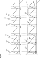
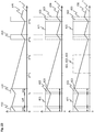
- the stator conductors to be energized can be supplied with an electrical voltage clocked by means of pulse width modulation and, as a result, with periodic voltage pulses predetermined by a PWM clock frequency or by a time pattern of the pulse width modulation.
- the electrical current generated in energized stator conductors can be superimposed with an alternating current component, the so-called ripple current.
- ripple current This is due to a smoothing effect of the stator conductors serving as primary coils, as a result of which the current flowing in the energized stator conductors follows the pulse-width-modulated voltage in such a way that a sawtooth-like or triangular current curve is present.
- the current can swing back and forth around an average value.
- the occurrence of the ripple current is associated with a magnetic field that changes over time, so that, as stated above, an electrical alternating voltage can be induced in the at least one armature coil of the armature.
- the influencing device used for data transmission from the stator to the rotor is designed which To influence current regulation in such a way that a change in relation to the ripple current is caused in energized stator conductors.
- ripple current can have an increased or decreased oscillation width (peak-valley value, English peak-to-peak amplitude) compared to the unaffected state.
- the drive of the rotor is based on a magnetic interaction between the energized stator conductors of the stator and the magnet device of the rotor.
- the rotor can be held floating above the stator and also moved.
- the stator conductors of the stator can be interconnected to form multiphase systems that can be energized independently of one another.
- the drive of the rotor can be based on the mean value of the current flowing in the energized stator conductors.
- the ripple current caused by the pulse-width-modulated current supply can have no or only a small and therefore negligible influence on the driving of the rotor.
- the current control can be referred to as direct current control or DC current control.
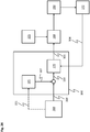
- the stator has a plurality of current regulating devices, output stage devices connected to the stator conductors or multi-phase systems, and current measuring devices for carrying out the current regulation.
- the output stage devices can comprise a plurality of output stages.
- the current measuring devices can be designed to detect actual current values of stator conductors or multi-phase systems. This can be done by scanning. The actual current values can be transmitted to the current regulating devices together with setpoint current values.
- the current regulating devices can be designed to generate control signals based on the actual current values and setpoint current values.
- the control signals which are pulse-width modulated Control signals can act can be applied to the output stage devices.
- pulse-width-modulated or clocked voltage pulses can be applied to the stator conductors or multi-phase systems of the stator, whereby these are periodically energized.
- the output stage devices can be supplied with an intermediate circuit voltage.
- the intermediate circuit voltage can be provided by an intermediate circuit of the stator.
- the planar drive system may have a main control device.
- the main control device can be designed to generate setpoint current values for energizing stator conductors or multi-phase systems of the stator.
- the target current values can be transmitted to the aforementioned current regulating devices.
- the main control device can furthermore be designed to establish a system clock of the planar drive system, according to which the timing of the operation of the planar drive system can be based.
- time parameters of the current control such as the PWM clock frequency, can be specified based on the system clock.
- the PWM clock frequency can be in the kHz range, for example in the two-digit kHz range, and for example 64 kHz. This applies correspondingly to the frequency of the alternating magnetic field and thus to the frequency of the alternating voltage induced in the armature coil.
- the stator conductors of the stator are interconnected to form multiphase systems that can be energized independently of one another.
- Each multi-phase system can have a plurality of coils formed from stator conductors.
- the multi-phase systems can also be referred to as coil systems or multi-coil systems.
- some of the multiphase systems can be energized at the same time or be energized in a pulse-width-modulated manner. The energization of several multiphase systems can take place synchronously or essentially synchronously in time.
- the stator can also be designed to apply a multiphase current to its multiphase systems.
- Each coil of an energized multi-phase system can be fed with a corresponding phase of the current.
- the current control carried out for this purpose with the help of the stator can be based on a center-centered Pulse width modulation (Center Aligned PWM) takes place, in which the coils of a multiphase system are acted upon with voltage pulses centered on one another with respect to the PWM clock frequency or a time pattern of the pulse width modulation.
- Center Aligned PWM Center Aligned PWM
- the multiphase systems of the stator can be three-phase systems or three-coil systems, which each comprise three coils formed from stator conductors and each connected to a common star point.
- a three-phase current can be applied to such coil systems.
- the output stage devices can be implemented in the form of circuits with triple half bridges.
- the stator can furthermore be designed to carry out its own current regulation for each multi-phase system.
- the stator can have a current control device and an output stage device for each multi-phase system.
- the stator can also have a current measuring device for each multi-phase system.
- the stator can have a current measuring device for a group of several multiphase systems, which enables a cost-effective design of the stator.
- the stator of the planar drive system has one or more stator modules. In an embodiment with a plurality of stator modules, these can be arranged laterally next to one another.
- a stator module can have several of the above-mentioned components, that is to say several stator conductors or multi-phase systems, current regulating devices, output stage devices and current measuring devices.
- the or each stator module can have an intermediate circuit and a module control device.
- the module control device can be implemented, for example, in the form of an FPGA (Field Programmable Gate Array).
- the module control device can have the current regulating devices of the relevant stator module and, depending on the embodiment, possibly at least one further device.
- the above-mentioned further device of the module control device of a stator module can be the influencing device described above and used for data transmission from the stator to the rotor, which is used to influence the energization of stator conductors or of at least one polyphase system can be used.
- the following configurations can also be used for the influencing device.
- the influencing device is designed to suppress voltage pulses from being applied to stator conductors or to at least one multiphase system of the stator during current regulation.
- individual or multiple voltage pulses can be switched off at times in a targeted manner. Switching off voltage pulses is associated with suppressing the ripple current flowing in the relevant stator conductors or multi-phase systems, whereby the generation of the alternating magnetic field and thus the occurrence of the induction voltage in the at least one armature coil of the armature can be suppressed or essentially suppressed.
- parasitic capacitive couplings between the stator and the rotor which may impair a voltage measurement carried out on the rotor as part of the data transmission to detect changes in the induction voltage, can also be reduced or be suppressed.
- the influencing device is designed to influence the current regulation of at least one multiphase system in such a way that voltage pulses with matching pulse widths are applied to the multiphase system.
- This embodiment is based on the fact that a multi-phase system is electrically controlled in the current regulation or in the uninfluenced state with centrally centered voltage pulses with different pulse widths, whereby a ripple current also flows in the multi-phase system. If the voltage pulses have the same pulse width, the ripple current does not exist.
- the ripple current flowing in the multi-phase system can consequently be suppressed, and thus the occurrence of the induction voltage in the at least one rotor coil of the rotor can be suppressed or substantially suppressed.
- the following embodiment can be used for the influencing device provided for data transmission from the stator to the rotor be considered.
- the influencing device is designed to interrupt the control signals generated by at least one current regulating device of the stator used for current regulation or the transmission of the control signals generated by at least one current regulating device, so that the control signals are not applied to at least one output stage device.
- the at least one output stage device can be operated or controlled in such a way that the ripple current is suppressed in at least one multiphase system, and thus the occurrence of the induction voltage in the at least one armature coil of the armature can be suppressed or substantially suppressed. This can be done, for example, by applying changed control signals to the at least one output stage device with the aid of the influencing device.
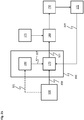
- the influencing device can have, for example, a data control device and an interrupt device.
- the interruption device can be used to interrupt the control signals generated by at least one current regulating device.
- the application of changed control signals to at least one output stage device can also be carried out with the aid of the interruption device.
- the data control device can be used to control or temporarily control the interruption device in order to temporarily interrupt and thus suppress the ripple current in at least one multiphase system.
- the data control device can be controlled by the main control device of the planar drive system, which can transmit data signals to the data control device. Based on this, the data control device can control the interruption device.
- the influencing device is designed to influence or change setpoint current values used in the current regulation.
- influenced or changed setpoint current values can be transmitted to at least one current control device.
- the current regulation of at least one multi-phase system can be influenced, and a change in relation to the magnetic alternating field and the alternating voltage which can be induced in the at least one armature coil of the armature can thereby be brought about.
- the influencing device is designed to influence at least one current control device and thus to influence the control signals generated by the at least one current control device. In this way, influenced or changed control signals can be applied to at least one output stage device will. In this way, too, the current regulation of at least one multi-phase system can be influenced, and a change in relation to the magnetic alternating field and the alternating voltage which can be induced in the at least one armature coil of the armature can be brought about.
- the stator can have an influencing device or, in an embodiment of the stator with a plurality of stator modules, one influencing device per stator module.
- the current regulation can be temporarily influenced by one or more multiphase systems.
- the stator it is also possible for the stator to have its own influencing device for each multi-phase system and thus for each current control device.
- One or more influencing devices can each be integrated in a module control device of a stator module.
- one or more influencing devices can be controlled by the main control device of the planar drive system.
- the main control device can transmit corresponding control or data signals to one or more influencing devices. In this way, the current regulation can be influenced by at least one multi-phase system.
- a plurality of multiphase systems that are energized at the same time can also be components of a plurality of adjacent stator modules.
- the runner and thus the at least one runner coil of the runner can be located in the area of influence of the several multi-phase systems and be exposed to the influence of a resulting alternating magnetic field, which is caused by the superposition of several alternating magnetic fields, each caused by those in the multi-phase systems flowing ripple currents.
- the alternating voltage induced in the armature coil can be dependent on the resulting alternating magnetic field.
- the energization of at least one multi-phase system there is the possibility of influencing the energization of at least one multi-phase system. If the energization of several multiphase systems is influenced, this can be carried out with the aid of one or more influencing devices of the stator. Furthermore, the influencing of the plurality of multiphase systems can take place synchronously with one another in terms of time.
- the stator is designed to temporarily influence the energization of stator conductors or of at least one multiphase system in a modulated form.
- the data is transmitted from the stator to the rotor using modulation.
- modulation can be, for example, phase modulation, amplitude modulation or frequency modulation.
- Such a data transmission from the stator to the rotor using modulation can be implemented with the aid of one or more influencing devices of the stator.
- the influencing device (s) can be activated by the main control device of the planar drive system in order to influence the current supply to stator conductors or the current regulation of at least one multiphase system in a correspondingly modulated manner.
- a useful signal to be transmitted can be modulated onto a carrier signal or a carrier frequency of a carrier signal as part of the data transmission from the stator to the rotor by temporarily or modulated influencing the current supply to stator conductors.
- the useful signal can include the data signals or symbols provided for the transmission.
- the carrier signal modulated in this way with the useful signal can be contained in the induction voltage measured in the rotor, so that the useful signal can be inferred by evaluating the same.
- the carrier frequency used in the data transmission from the stator to the rotor can be lower than the PWM clock frequency of the current regulation.
- the PWM clock frequency can be a multiple of the carrier frequency.
- the carrier frequency can be in the kHz range, for example in the single-digit kHz range. For example, the frequency range from 1 kHz to 2 kHz is possible.
- the stator can also be designed to carry out the transmission of data signals or symbols in each case extended to a predetermined length by sending the relevant symbols with a predetermined repetition.
- the information content of a symbol for example a bit or dibit, is transmitted by sending the relevant symbol several times in succession will.
- modulation to a pseudo-random sequence or the use of a pseudo-random sequence as the carrier signal, or also, for example, the use of several carrier frequencies, is possible.
- the rotor has a voltage measuring device for measuring the alternating voltage induced in the at least one rotor coil. On the basis of the measured induction voltage, the change in the induction voltage caused as a result of influencing the energization of stator conductors or of at least one multiphase system can be detected, and data signals or symbols generated by the stator can be determined as a result.
- the voltage measuring device can be connected to the at least one armature coil of the armature.
- the rotor has a processing device for evaluating the measured induced alternating voltage.
- the processing device can be supplied with the aid of the direct voltage provided by the rectifier described above.
- the processing device can be connected to the voltage measuring device described above.
- the data signals or symbols generated by the stator can be determined through the evaluation. If the data is transmitted from the stator to the rotor, as stated above, using modulation, the processing device can be designed to evaluate the measured induction voltage by means of a correlation using at least one reference signal.
- measured voltage values of the induction voltage for the length of a symbol can be multiplied by the at least one reference signal, and the products can be added up. If a symbol as stated above is sent several times in succession, the length is the extended length of the symbol sent several times. Carrying out the data communication from the stator to the rotor using modulation results in that all Components of a voltage signal of the induction voltage on which the evaluation is based can be uncorrelated to the reference signal except for the useful signal. With the help of the correlation, a suppression of disturbance variables that can be adjusted via the symbol length and thus an improvement in the signal-to-noise ratio can be achieved.
- the at least one reference signal can have a frequency matched to the carrier signal or its carrier frequency or a frequency corresponding to the carrier frequency.
- the at least one armature coil of the armature different configurations are conceivable. It is possible, for example, for the at least one armature coil of the armature to be implemented in the form of a wound or circumferential metallic wire.
- the rotor has at least one printed circuit board (PCB).
- the at least one printed circuit board can have multiple layers.
- the at least one armature coil of the armature can be implemented in the form of one or more spiral-shaped metallic conductor tracks of the at least one circuit board.
- the rotor can, for example, have a single printed circuit board with one or more spiral conductor tracks, which can form one or more rotor coils. Furthermore, the rotor can have a plurality of separate circuit boards each with one or more spiral-shaped conductor tracks, which can each form one or more rotor coils. Several spiral-shaped conductor tracks or armature coils can be connected to one another electrically or electrically in series.
- the at least one rotor magnet of the magnet device of the rotor can be a permanent magnet.
- the magnet device of the rotor can have several rotor magnets.
- the rotor magnets can be arranged in such a way that the rotor magnets surround an area.
- the magnetic device can have a rectangular or square contour.
- the at least one armature coil of the armature is arranged in the area surrounded by the armature magnets of the magnetic device.
- a multi-layer printed circuit board with several layers arranged one above the other and several spiral conductor tracks arranged one above the other can be used.
- the circuit board can be relatively easily converted into be integrated with the runner.
- the runner can have an exposed recess in its center, within which the printed circuit board can be arranged.
- the number of layers of the circuit board and the spiral-shaped conductor tracks can be six or eight, for example.
- the printed circuit board used can, for example, have a thickness of 1 mm.
- the rotor has a plurality of rotor coils which are arranged in an area below the magnet device of the rotor.
- a multi-layer printed circuit board with several layers and several spiral-shaped conductor tracks arranged one above the other can be used. In the area of each layer, there can also be a plurality of spiral-shaped conductor tracks arranged next to one another.
- the circuit board can be arranged on the underside of the runner and extend over the entire or substantially the entire surface of the runner. Since in this embodiment the flying height of the rotor can be reduced by the thickness of the circuit board, it can be considered to use a relatively flat circuit board.
- the printed circuit board used can, for example, have two layers and a thickness of, for example, 0.3 mm.
- the rotor has a plurality of rotor coils which are arranged in the area of lateral outer sides of the rotor.
- several multi-layer printed circuit boards with several layers and several spiral conductor tracks arranged one above the other can be used.
- the printed circuit boards used can have, for example, six or eight layers and a thickness of, for example, 1 mm.
- the circuit boards can be integrated in spacers of the runner, which can be present in the area of the lateral outer sides of the runner.
- the rotor can also be arranged on or on at least one printed circuit board of the rotor.
- the rotor has a rotor coil in an area laterally surrounding the magnet device.
- the armature coil can be implemented in the form of a wound wire. It is also possible to use a circuit board running around the magnet device with spiral-shaped conductor tracks through which the armature coil can be formed.
- the planar drive system is designed for data transmission from the rotor to the stator.
- the rotor is designed to temporarily load the at least one rotor coil in order to temporarily cause an increased current consumption of energized stator conductors of the stator.
- the load modulation method is used.
- the electrical loading of the armature coil has the consequence that energy is withdrawn from the alternating magnetic field generated with the aid of the stator or withdrawn in an increased form.
- the energy extraction due to the loading of the armature coil consequently leads to an increased power consumption of energized stator conductors of the stator.
- By temporarily loading the armature coil a correspondingly increased current consumption of energized stator conductors of the stator can temporarily be brought about, and information can be transmitted from the rotor to the stator on the basis of this.
- the armature can be designed to short-circuit the armature coil.
- the rotor is designed to short-circuit a coil part of the at least one rotor coil for the temporary electrical loading of the at least one rotor coil. In this way it can be ensured that the induction voltage does not collapse or only partially collapses during the loading of the armature coil, as a result of which the inductive energy transfer from the stator to the armature can be maintained.
- the rotor has a switching device for short-circuiting.
- the switching device can be connected to the at least one armature coil.
- the switching device can be designed in the form of a transistor.
- the rotor has a load resistor, via which the coil part of the at least one rotor coil is short-circuited.
- the load resistor can be connected to the at least one armature coil. With the help of the load resistance, the amount of energy drawn from the alternating magnetic field can be determined when the armature coil is loaded.
- the coil part used for short-circuiting is a lowermost coil part of the at least one armature coil.
- This coil part which can include a spiral-shaped conductor track of the at least one armature coil, can face the stator when the planar drive system is in operation.
- the coil part in question can also have the smallest distance from the stator conductors of the stator compared to another coil part of the at least one armature coil. In this way, a high inductive coupling can be achieved between the coil part of the rotor used for short-circuiting and the stator conductors of the stator that are energized. The effect brought about by the short-circuit of causing an increased current consumption in the stator can thereby be as great as possible.
- the coil part used for short-circuiting has a larger conductor cross-section than in at least one other coil part of the at least one armature coil.
- the coil part used for short-circuiting can have a high or, compared to another coil part, a higher coil quality. This also favors the existence of a high inductive coupling between the coil part used for short-circuiting and the stator conductors of the stator that are energized.
- the rotor has a control device for controlling the temporary loading of the at least one rotor coil.
- the control device can be connected to the above-described switching device of the rotor and can be designed to control the switching device.
- the control device can also be supplied with the aid of the direct voltage provided by the rectifier described above.
- the control device can be the processing device described above and used in the context of data transmission from the stator to the rotor for evaluating the measured induction voltage.
- the above-described short-circuiting of a coil part can relate to only one rotor coil, or to several or all of the rotor coils of the rotor.
- the coil part used for short-circuiting can be formed, for example, from interconnected subsections or conductor tracks of a plurality of rotor coils.
- the relevant subsections can be connected to one another in series and be the lowest subsections of the armature coils, that is to say, when the planar drive system is in operation, facing the stator.
- the loading of the rotor coil can take place intermittently or in a pulsed manner in order to thereby cause an intermittent or pulsed current consumption in the stator.
- the stator can, as will be explained in more detail below, have a total current measuring device for measuring a total current of energized stator conductors. By evaluating the total current measured, conclusions can be drawn about the data signals generated by the rotor or these can be determined.
- the rotor is designed to temporarily load the at least one rotor coil in a modulated form.
- the modulation used can be, for example, phase modulation, amplitude modulation or frequency modulation.
- Such data transmission using modulation can be implemented with the aid of the control device and the switching device of the rotor.
- a useful signal to be transmitted can be modulated onto a carrier signal or a carrier frequency of a carrier signal.
- the useful signal can include the data signals or symbols provided for the transmission.
- the carrier signal modulated with the useful signal in this way can be contained in the total current measured at the stator, so that the useful signal can be inferred by evaluating it.
- the carrier frequency can be lower than the PWM clock frequency of the current control.
- the carrier frequency can be in the kHz range, for example in the single-digit kHz range. For example, the frequency range from 1 kHz to 2 kHz is possible.
- the runner can also be designed to carry out the transmission of data signals or symbols in each case extended to a predetermined length by sending the relevant symbols with a predetermined repetition. Further refinements are also conceivable for carrying out the data transmission in modulated form. For example, modulation to a pseudo-random sequence or the use of a pseudo-random sequence as the carrier signal, or also, for example, the use of several carrier frequencies, is possible.
- the stator has a total current measuring device for measuring a total current of energized stator conductors or multi-phase systems. On the basis of the measured total current, the increased current consumption of the stator caused as a result of the loading of the at least one armature coil of the armature can be detected, and data signals generated by the armature can be determined as a result.
- the total current measuring device can arranged between an intermediate circuit and a plurality of output stage devices of the stator used to energize stator conductors or multi-phase systems, and be connected to the intermediate circuit and the output stage devices. In this way, the total current measuring device can detect the current consumption of the relevant multi-phase systems.
- each stator module can have a total current measuring device. This can be arranged between the intermediate circuit and the output stage devices of the respective stator module. The total current measured with the help of a total current measuring device can refer to the associated intermediate circuit.
- the stator has a bandpass filter for filtering the measured total current.
- the bandpass filter can be connected to the above-described total current measuring device and arranged downstream of it. This refinement can be used when the data is transmitted from the rotor to the stator, as indicated above, using modulation.
- the bandpass filter can have a pass band in the range of the carrier frequency used.
- each stator module can have a bandpass filter. This can be arranged downstream of the total current measuring device of the respective stator module.
- the stator has an evaluation device for evaluating the total current.
- the evaluation device can be connected to the bandpass filter described above and arranged downstream of it, and can thereby be provided for evaluating the measured and filtered total current.
- the data signals or symbols generated by the runner can be determined through the evaluation.
- the evaluation can include generation of evaluation signals or evaluation data by the evaluation device, which reproduce the data signals or symbols transmitted by the runner. If the data is transmitted from the rotor to the stator using modulation as specified above, the evaluation device can be designed to evaluate the measured and filtered total current by means of a correlation using at least one reference signal.
- the main control device of the planar drive system can also be included in the evaluation.
- the main control device can receive the evaluation signals generated by the evaluation device and, in the case of an embodiment of the stator with a plurality of stator modules, the evaluation signals from one or more evaluation devices of the respective stator modules generated evaluation signals are transmitted.
- the main control device can be designed to further process the evaluation signals coming from the stator in order to determine the data signals or symbols generated by the rotor on the basis thereof.
- a reference clock With regard to the data transmission from the rotor to the stator, the use of a reference clock can be considered.
- the alternating magnetic field generated by the stator or its frequency can be used as the reference clock.
- the rotor is designed to carry out the temporary loading of the at least one rotor coil in a time-coordinated manner with the alternating magnetic field generated with the aid of the stator.
- the rotor voltage measuring device mentioned above and used to measure the alternating voltage induced in the rotor coil can be used. Based on the measured alternating voltage, its frequency and thus the frequency of the alternating magnetic field can be determined, and the loading of the armature coil can be carried out in a coordinated manner.
- the rotor can have a control device for controlling the temporary loading of the at least one rotor coil.
- the control device can be connected to the voltage measuring device described above and designed to evaluate the measured alternating voltage. On the basis of the measured alternating voltage, the control device can determine the frequency of the alternating voltage and thus the frequency of the magnetic alternating field. In accordance with this, the control device can load the at least one armature coil, which can be done in modulated form as indicated above.
- the stator or the or each evaluation device of the stator is designed according to a further embodiment to carry out the evaluation of the total current in a time-coordinated manner with the alternating magnetic field generated with the aid of the stator.
- a reference signal used in the evaluation can be synchronized as well as possible to the carrier signal.
- the planar drive system can be designed as described above or in accordance with one or more of the embodiments described above.
- the planar drive system has a stator and a rotor.
- the stator has several stator conductors that can be energized.
- the rotor has a magnet device with at least one rotor magnet.
- the energization of stator conductors is carried out in such a way that an alternating magnetic field is generated with the aid of energized stator conductors.
- the rotor has at least one rotor coil in which an alternating voltage is induced on the basis of the alternating magnetic field.
- data is also transmitted from the stator to the rotor.
- the energization of the stator conductors of the stator is temporarily influenced, which temporarily causes a change in relation to the alternating voltage induced in the at least one armature coil of the armature.
- Reliable data transmission from the stator to the rotor can be achieved with the aid of the proposed method.
- the data is transmitted by temporarily influencing the energization of the stator conductors of the stator, which temporarily causes a change in relation to the alternating magnetic field generated by the stator, and thus temporarily a change in relation to the alternating voltage induced in the at least one armature coil of the armature.
- By influencing the energization of stator conductors in an intermittent or pulsed manner data signals or symbols can consequently be transmitted from the stator to the rotor.
- stator conductors by influencing the energization of stator conductors, a weaker or stronger alternating magnetic field is generated compared to an uninfluenced energization, and thus a smaller or greater electrical alternating voltage is induced in the at least one armature coil. It is also possible that, by influencing the current supply, the generation of the magnetic alternating field, and thus the induction of the alternating voltage, is suppressed or essentially suppressed.
- the induction voltage can be used not only in the context of data transmission, but also for inductive energy transmission from the stator to the rotor. In this sense, rectification and thereby conversion of the induced alternating voltage can also be carried out take place in a DC voltage. This can be done with the help of a rectifier of the rotor.
- the temporary influencing of the energization of stator conductors can be carried out with the aid of at least one influencing device of the stator.
- the at least one influencing device can be controlled by a main control device of the planar drive system.
- stator conductors are energized by a current control based on pulse width modulation.
- the temporary influencing of the energization of stator conductors which, as stated above, can be carried out by means of at least one influencing device of the stator, takes place by influencing the current regulation.
- the stator conductors to be energized can be controlled electrically with an electrical voltage clocked by means of pulse width modulation, and consequently with periodic voltage pulses.
- a ripple current can be generated in energized stator conductors, and thereby the alternating magnetic field.
- the current regulation is influenced in such a way that a change in relation to the ripple current in energized stator conductors is caused.
- it is possible to temporarily suppress the ripple current as a result of which the generation of the alternating magnetic field and thus the occurrence of the induction voltage in the at least one armature coil of the armature can be temporarily suppressed or substantially suppressed.
- the stator conductors of the stator can be interconnected to form multiphase systems that can be energized independently of one another.
- the multiphase systems can be acted upon with centrally centered voltage pulses.
- a separate current control can be carried out for each energized multi-phase system.
- the current regulation can be carried out with the help of components of the Stators such as current regulating devices, output stage devices and current measuring devices connected to the stator conductors or multi-phase systems are carried out.
- the current regulation is influenced by suppressing the application of voltage pulses to stator conductors or to at least one multiphase system of the stator during the current regulation. Individual or multiple voltage pulses can be omitted from time to time. This procedure leads to a suppression of the ripple current flowing in the relevant stator conductors or multi-phase systems, whereby the generation of the magnetic alternating field and thus the induction of the alternating voltage in the at least one armature coil of the armature can be suppressed or substantially suppressed.
- the current regulation of at least one multiphase system is influenced in such a way that the multiphase system with voltage pulses with matching pulse widths is applied.
- the ripple current flowing in the polyphase system can also be suppressed, and the occurrence of the induction voltage in the at least one armature coil of the armature can thereby be suppressed or substantially suppressed.
- the stator can have a plurality of stator modules.
- Each stator module can have several stator conductors or multi-phase systems, current regulating devices, output stage devices and current measuring devices.
- each stator module can have one or more influencing devices used for influencing the current flow to stator conductors or by at least one multi-phase system.
- the temporary influencing of the energization of stator conductors or of at least one multiphase system is carried out in a modulated form, that is to say using a modulation.
- the modulation used can be, for example, phase modulation, amplitude modulation or frequency modulation.
- the induced alternating voltage is measured in order to detect the change in relation to the induced alternating voltage.
- the change in the induction voltage caused as a result of influencing the energization of stator conductors or of at least one multiphase system can be determined, and conclusions can be drawn about the data signals or symbols generated by the stator.
- the measurement of the induced alternating voltage can be carried out with the help of a voltage measuring device of the rotor.
- the measured induced alternating voltage is evaluated.
- the data signals or symbols generated by the stator can be determined through the evaluation.
- the evaluation can include correlating the measured induction voltage with at least one reference signal.
- the evaluation can be carried out with the aid of a processing device of the runner.
- data is transmitted from the rotor to the stator.
- the at least one armature coil of the armature is temporarily loaded and this temporarily causes an increased current consumption by energized stator conductors of the stator.
- data signals or symbols can be transmitted from the armature to the stator.
- the at least one armature coil can be temporarily loaded by short-circuiting the armature coil.
- a coil part of the at least one armature coil is short-circuited for the temporary loading of the at least one armature coil.
- the coil part can be short-circuited via a load resistor.
- the short-circuiting can be carried out with the aid of a switching device on the rotor.
- the temporary loading of the at least one armature coil can be controlled with the aid of a control device of the armature.
- the aforementioned switching device can be activated by the control device.
- the at least one armature coil is temporarily loaded in a modulated form, that is to say using a modulation.
- the used Modulation can be phase modulation, amplitude modulation or frequency modulation, for example.
- the temporary loading of the at least one armature coil is carried out in a time-coordinated manner with the alternating magnetic field generated with the aid of the stator.
- the induced alternating voltage can be measured and its frequency determined.
- the induction voltage can be measured using a voltage measuring device on the rotor.
- the frequency of the alternating voltage can be determined with the aid of the aforementioned control device of the rotor.
- a total current of energized stator conductors or multiphase systems of the stator is measured in order to detect the increased current consumption.
- the increased current consumption of the stator caused as a result of the loading of the at least one armature coil of the armature can be determined, and conclusions can be drawn about data signals or symbols generated by the armature.
- the total current can be measured using a total current measuring device on the stator.
- the measured total current is filtered.
- the measured total current can be filtered using a bandpass filter on the stator.
- the measured total current is evaluated.
- Evaluation signals or evaluation data can be provided, which can reproduce data signals or symbols transmitted by the runner.
- the total current can be evaluated after filtering.
- the evaluation of the total current can be carried out in a time-coordinated manner with the alternating magnetic field generated with the aid of the stator.
- the evaluation can include correlating the total current with at least one reference signal.
- the evaluation can be carried out with the aid of an evaluation device of the stator.
- Embodiments of a planar drive system and a method for operating a planar drive system are described on the basis of the following schematic figures.
- the planar drive system which comprises a planar stator and a movable rotor, is suitable both for reliable inductive energy transmission from the stator to the rotor and for reliable data transmission between the stator and the rotor.
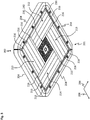
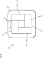
- FIG. 1 shows a perspective illustration of an embodiment of a planar drive system 1, which has a stator 5 with at least one stator module 10 and a rotor 200.
- the rotor 200 is movably arranged above the stator 5 and the stator module 10 during the operation of the planar drive system 1.
- the stator module 10 comprises a module housing 18 and a stator unit 100, which is arranged on an upper side of the module housing 18.
- the stator unit 100 is designed as a planar stator and has a flat or planar stator surface 11.
- the stator surface 11 extends over the entire top of the stator unit 100 and of the stator module 10.
- the stator unit 100 has a plurality of metallic stator conductors 125 that can be acted upon by electrical drive currents.
- the stator conductors 125 can also be referred to as coil conductors or conductor strips.
- a magnetic field can be generated, which the rotor 200 interacts with a magnetic device 201 of the rotor 200 (cf. Figure 3 ) can drive.
- the rotor 200 can be held in a floating manner above the stator surface 11 and can also be moved.
- the rotor 200 can be moved both in a first direction 12 and in a second direction 14.
- the first and second directions 12, 14 are perpendicular to one another and are each oriented parallel to the stator surface 11.
- the rotor 200 is moved simultaneously in the first direction 12 and in the second direction 14, the rotor 200 can be moved in any direction over the stator surface 11.
- Movement of the rotor 200 is also possible in a third direction 15 oriented perpendicular to the first direction 12, the second direction 14 and the stator surface 11. In this way, the distance between the rotor 200 and the stator surface 11 can be varied, that is to say the rotor 200 can be raised or lowered above the stator surface 11.
- stator module 10 In the module housing 18 are in Figure 1 Further electrical and electronic components and devices (not shown) of the stator module 10 are arranged. These components are used, among other things, to generate electrical drive currents and thereby to supply current to stator conductors 125 of stator module 10. As will be explained in more detail below, current is supplied by current regulation based on pulse width modulation. Components of the stator module 10 used for data transmission with the rotor 200, which will also be discussed in greater detail below, can also be contained in the module housing 18.
- connection lines 16 can comprise an energy supply line for supplying the stator module 10 with electrical energy, an input data line and an output data line.
- the stator module 10 can be supplied with electrical energy via the energy supply line, for example for generating drive currents.
- Data can be sent to the stator module 10 and from the stator module 10 via the input and output data line.
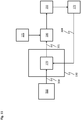
- a main control device 500 cf. Figure 11
- This includes, for example, the transmission of control signals or control data such as electrical target current values or other data signals from the main control device 500 to the stator module 10.
- the module housing 18, the stator unit 100 and the stator surface 11 are rectangular or square in the plan view of the stator surface 11.
- the stator surface 11 is delimited by four straight outer edges 21 in each case. In each case two opposing outer edges 21 are oriented parallel to the first direction 12 and two opposing further outer edges 21 are oriented parallel to the second direction 14.
- the stator module 10 and the module housing 18 furthermore have four flat side surfaces 33 between the stator surface 11 and the opposite underside 32, which end flush with the outer edges 21 on the stator surface 11.
- the stator 5 of the planar drive system 1 can be used not only with one stator module 10, but also with several structurally identical copies of the in Figure 1 be realized stator module 10 shown.
- the plurality of stator modules 10 can be arranged next to one another in such a way that the outer edges 21 and side surfaces 33 of adjacent stator modules 10 lie against one another. In this way, the stator surfaces 11 of the stator modules 10 can form a coherent work surface over which the rotor 200 can be moved without interruption. This takes place by a corresponding energization of the stator conductors 125 of the stator modules 10 and thereby generating a magnetic field driving the rotor 200.
- FIG 2 Illustrative shows Figure 2 a perspective view of an embodiment of the stator 5 with six stator modules 10 arranged next to one another 14 extended second rows or columns arranged side by side.
- the stator surfaces 11 of the stator modules 10 form a coherent and planar working surface for the rotor 200.
- the rotor 200 can be moved seamlessly from the stator surface 11 of one stator module 10 to or over the stator surface 11 of an adjacent stator module 10.
- stator 5 of the planar drive system 1 other configurations with other arrangements and / or other numbers of stator modules 10 arranged next to one another can also be considered for the stator 5 of the planar drive system 1.
- the stator modules 10 can in principle be joined together in the first and / or second direction 12, 14 to form a stator 5 of any size.
- the above-mentioned energy supply and data communication with the main control device 500 can be implemented in each of the stator modules 10 of the stator 5 via their own connection lines 16 of the stator modules 10.
- Alternative configurations of the stator modules 10, not shown here, can also have electrical connection elements, by means of which electrical energy and / or data can be transmitted from one stator module 10 to an adjacent stator module 10.
- Such fasteners can for example be arranged on the side surfaces 33 of the stator modules 10.
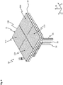
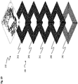
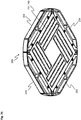
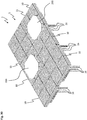
- Figure 3 shows an embodiment of the rotor 200 of the planar drive system 1 in a perspective view from below of an underside of the rotor 200.
- the underside of the rotor 200 faces the stator surface 11 of the stator module 10 or of several stator modules 10 of the stator 5 .
- the rotor 200 or its underside are also oriented parallel or essentially parallel to the stator surface 11.
- the rotor 200 has a magnet device 201 on the underside.
- the magnet device 201 has a rectangular or square outer contour and comprises a first magnet unit 210, a second magnet unit 212, a third magnet unit 213 and a fourth magnet unit 214.
- the first magnet unit 210 and the third magnet unit 213 each face one another in a first rotor direction 206 elongated rotor magnets 216 arranged and extended along a second rotor direction 208 oriented perpendicular to the first rotor direction 206.
- the second magnet unit 212 and the fourth magnet unit 214 each have elongate rotor magnets 216 which are arranged next to one another in the second rotor direction 208 and extend along the first rotor direction 206.
- the rotor magnets 216 are permanent magnets.
- the first and third magnet units 210, 213 are used to drive the rotor 200 in the first rotor direction 206 when the planar drive system 1 is in operation.
- the second and fourth magnet units 212, 214 are used to drive the rotor 200 in the second rotor direction 208 during operation.
- the magnet units 210, 212, 213, 214 of the magnet device 201 and their rotor magnets 216 are arranged in such a way that they surround an area.
- the rotor 200 has according to the FIG Figure 3
- the embodiment shown has a first printed circuit board 230 with an armature coil 240.
- the armature coil 240 is used, together with the stator conductors 125 of the stator 5, for inductive energy transmission from the stator 5 to the armature 200, and for data transmission between the stator 5 and the armature 200.
- stator conductors 125 generates a ripple current and thus an alternating magnetic field, so that an alternating electrical voltage can be induced in the armature coil 240.
- the induced alternating voltage can be essentially proportional to the change over time of the magnetic flux passing through the armature coil 240.
- the induced alternating voltage can be used for the energy supply, and for this purpose with the aid of a rectifier 260 of the rotor 200 (cf. Figure 13 ) rectified
- configurations with several rotor coils 240 are also conceivable for the rotor 200 (cf. Figure 27 ).
- the rotor 200 further has four spacers 204 which surround the magnet device 201 and form lateral outer sides of the rotor 200.
- the spacers 204 can ensure that when the spacers 204 of two runners 200 arranged next to one another are in contact, a minimum distance is maintained between the magnetic devices 201 of the runners 200. In this way it can be avoided that the undersides of the rotors 200 are erected by an attractive force between their magnetic devices 201 from the position parallel to the stator surface 11 and the two rotors 200 remain magnetically adhered to one another with the undersides facing each other.
- the spacers 204 can comprise an elastically deformable material or can be formed from such a material.
- FIG. 11 shows a perspective view of the stator module 10 without the rotor 200.
- stator 5 with several stator modules 10, as shown by way of example in FIG Figure 2
- all stator modules 10 can be constructed identically or essentially identically. For this reason, the details described above and below with regard to all stator modules 10 of the stator 5 can be used.
- the stator unit 100 of in Figure 4 The illustrated embodiment of the stator module 10 comprises a first stator sector 110, a second stator sector 112, a third stator sector 113 and a fourth stator sector 114.
- the stator sectors 110, 112, 113, 114 in turn each comprise a part of the stator conductors 125, each electrically insulated from one another Stator conductor 125 is arranged completely in one of the stator sectors 110, 112, 113, 114.
- the stator sectors 110, 112, 113, 114 are rectangular.
- the stator sectors 110, 112, 113, 114 can be square, so that an extension of the stator sectors 110, 112, 113, 114 in the first direction 12 corresponds to an extension of the stator sectors 110, 112, 113, 114 in the second direction 14.
- the stator sectors 110, 112, 113, 114 each comprise a quarter of the area, ie one quadrant, of the stator unit 100.
- stator conductors 125 can be arranged in several superimposed stator layers or stator planes, each of the Stator layers only has stator conductors 125, which are extended either along the first direction 12 or along the second direction 14.
- stator sectors 110, 112, 113, 114 can be constructed identically or essentially identically.
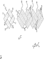
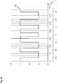
- FIG. 5 An exploded view of the magnet device 201 of the rotor 200 and the first stator sector 110 with four stator layers lying one above the other. Unless differences are described, the second, third and fourth stator sectors 112, 113, 114 are constructed identically to the first stator sector 110.
- the first stator sector 110 has a first stator layer 104, a second stator layer 106 arranged below the first stator layer 104, and two further stator layers 108 arranged below the second stator layer 106.
- the first stator layer 104 only comprises stator conductors 125 which are arranged next to one another along the first direction 12 and are elongated along the second direction 14.
- the second stator layer 106 only comprises stator conductors 125 which are arranged next to one another along the second direction 14 and are elongated along the first direction 12.
- a first of the further stator layers 108 arranged under the second stator layer 106 comprises only stator conductors 125 which are elongated along the second direction 14, and a second of the further stator layers 108 arranged under the first of the further stator layers 108 only comprises stator conductors 125, which are elongated along the first direction 12.
- the first stator sector 110 can furthermore be selected from the in Figure 5 stator layers 104, 106, 108 shown have further stator layers 108 not shown. Overall, the first stator sector 110 thus alternately comprises first or further stator layers 104, 108 with stator conductors 125, which are only extended along the second direction 14, and second or further stator layers 106, 108 with stator conductors 125, which are only extended along the first direction 12 .
- stator module 10 apart from the based on Figure 5 described embodiment, another embodiment, not shown, with a different arrangement of stator layers 104, 106, 108 with stator conductors 125 elongated along the first direction 12 and along the second direction 14 can be considered.
- a possible example is an embodiment in which initially as in Figure 5 the first stator layer 104 with stator conductors 125 that are only extended along the second direction 14 and, below this, the second stator layer 106 with only the first direction 12 Stator conductors 125 is present.
- the first of the further stator layers 108 arranged under the second stator layer 106 can comprise stator conductors 125 only extended along the first direction 12, and the second of the further stator layers 108 arranged under the first of the further stator layers 108 only include stator conductors 125 extended only along the second direction 14 .
- Further stator layers 108 with a repetitive orientation of the stator conductors 125 corresponding to the previously described orientation of the four stator layers 104, 106, 108 can be present thereunder.
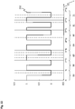
- stator conductors 125 of the first stator sector 110 are combined within the stator layers 104, 106, 108 to form stator segments 120, 121.
- the first stator sector 110 comprises in each stator layer 104, 106, 108 three stator segments 120, 121 arranged next to one another and adjoining one another.
- Each of the stator segments 120, 121 comprises six stator conductors 125 arranged next to one another.
- the first stator sector 110 comprises three in the first stator layer 104 first stator segments 120 and in the second stator layer 106 three second stator segments 121.
- the first stator segments 120 each include six adjacent stator conductors 125 extending along the second direction 14.
- the second stator segments 121 each include six adjacent stator conductors 125 extending along the first direction 12.
- the first stator sector 110 comprises, alternately or in a different order, three first stator segments 120 or three second stator segments 121 each.
- the first and second stator segments 120, 121 apart from their orientation, id entic dimensions.
- the rotor 200 can be oriented above the stator unit 100 in such a way that the first rotor direction 206 is oriented along the first direction 12 and the second rotor direction 208 is oriented along the second direction 14.
- Such an alignment is in Figure 5 illustrated.
- the first and third magnet units 210, 213 of the magnet device 201 of the rotor 200 can interact with the magnetic field generated by the stator conductors 125 of the first stator segments 120 in order to cause the rotor 200 to move along the first direction 12.
- the second and fourth magnet units 212, 214 of the magnet device 201 of the rotor 200 can interact with the magnetic field generated by the stator conductors 125 of the second stator segments 121 in order to cause the rotor 200 to move along the second direction 14.
- the first and third magnet units 210, 213 can use the magnetic field of the second stator segments 121 to drive the rotor 200 in the second direction 14, and the second and fourth magnet units 212, 214 can use the magnetic field of the first stator segments 120 to drive the Runner 200 cooperate in the first direction 12.
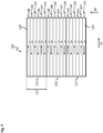
- FIG. 13 shows a top view of the first stator segments 120 of the first stator sector 110.
- a corresponding top view of the second stator segments 121 of the first stator sector 110 is shown in FIG Figure 7 illustrated.
- the second, third and fourth stator sectors 112, 113, 114 are constructed identically to the first stator sector 110.
- the stator segments 120, 121 have a segment width 127, which can be 40 mm, for example.
- stator conductors 125 of each of the individual stator segments 120, 121 of a corresponding stator layer 104, 106, 108 can each be energized with drive currents independently of the stator conductors 125 of the other stator segments 120, 121 of the relevant stator layer 104, 106, 108.
- the drive currents in one of the stator segments 120, 121 therefore do not necessarily depend on the drive currents in another of the stator segments 120, 121.
- the stator conductors 125 of one of the stator segments 120, 121 can have drive currents applied to them, while the stator conductors 125 of another, for example an adjacent stator segment 120, 121, are de-energized.
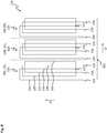
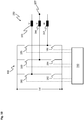
- the stator conductors 125 of the individual stator segments 120, 121 are each connected to a common star point 157 to form three-phase coil systems that can be energized independently of one another, hereinafter also referred to as three-phase systems 150 (cf. Figures 8 and 9 ).
- the three-phase systems 150 can have a three-phase electrical drive current applied to them when the planar drive system 1 is in operation.
- a first phase U, a second phase V and a third phase W of the drive currents can each have a phase offset of 120 ° with respect to one another.
- stator segments 120, 121 each have a first forward conductor 131 and a first return conductor 132 for the first phases U of the drive currents, a second forward conductor 141 and a second return conductor 142 for the second phases V of the drive currents and a third forward conductor 146 and a third return conductor 147 for the third phases W of the drive currents. Since the individual stator segments 120, 121 can each be energized independently of one another, the drive currents with which the individual stator segments 120, 121 are acted upon can be different.
- the individual first phases U with which the various stator segments 120, 121 can be acted upon
- the individual second phases V with which the various stator segments 120, 121 can be acted upon
- the individual third phases W with which the various stator segments 120, 121 can be acted upon
- the phases U, V and W can each be fed on a first side of the stator segments 120, 121 to the outgoing conductors 131, 141, 146 and on an opposite second side of the stator segments 120, 121 to the return conductors 132, 142, 147.
- the phases U, V and W can each be decoupled from the outgoing conductors 131, 141, 146 on the second side of the stator segments 120, 121 and on the first side of the stator segments 120, 121 from the return conductors 132, 142, 147.
- first forward and return conductors 131, 132 of first stator segments 120 lying one above the other on a plurality of first and further stator layers 104, 108 can each be connected in series.
- second forward and return conductors 141, 142 and the third forward and return conductors 146, 147 of first stator segments 120 lying one above the other on a plurality of first and further stator layers 104, 108 can each be connected in series.
- the phases U, V, W can each be coupled on one of the first and further stator layers 104, 108 into the forward conductors 131, 141, 146 of one of the first stator segments 120, then all of the forward associated with the relevant phase U, V, W and return conductors 131, 141, 146, 132, 142, 147 on all first and further stator layers 104, 108 of the relevant first stator segment 120 and finally brought together in a star point 157 (cf. Figure 8 ).
- the first forward and return conductors 131, 132, the second forward and return conductors 141, 142 and the third forward and return conductors 146, 147 can also be connected to a number of second and further stator layers 106, 108 one above the other Stator segments 121 connected in series and brought together in a star point 157 (cf. Figure 9 ).
- Figure 8 shows an equivalent circuit diagram of the first stator segments 120 of the first stator sector 110, which can be considered for the embodiment described above.
- the in Figure 8 The equivalent circuit diagram shown are all superimposed and in Series-connected stator conductors 125 of the first stator segments 120 shown as a single conductor.
- the first outgoing conductor 131 shown includes all outgoing conductors 131 of the first stator segments 120 that are superposed in different first and further stator layers 104, 108 and connected in series
- the first return conductor 132 shown includes all of the superimposed and series-connected first and further stator layers 104, 108 first return conductor 132 of the first stator segments 120.
- the illustrated second outward conductor 141, second return conductor 142, third outward conductor 146 and third return conductor 147 each include all second outward conductors 141, second return conductors 142, which are located one above the other in different first and further stator layers 104, 108 and are connected in series , third forward conductor 146 and third return conductor 147 of the first stator segments 120.
- stator conductors 125 or the forward and return conductors 131, 132, 141, 142, 146, 147 of the individual first stator segments 120 are each connected to form three-phase systems 150. With reference to the first stator segments 120, these are also referred to as first three-phase systems 151.
- a first connection point 154 for feeding in the first phases U, a second connection point 155 for feeding in the second phases V and a third connection point 156 for feeding in are each located on a first side 601 of the individual first stator segments 120, which is oriented along the first direction 12 third phases W arranged.
- the first connection point 154 can be connected to a first forward conductor 131 arranged in one of the first or further stator layers 104, 108.
- the second connection point 155 can be connected to a second forward conductor 141 arranged in one of the first or further stator layers 104, 108.
- the third connection point 156 can be connected to a third forward conductor 146 arranged in one of the first or further stator layers 104, 108.
- a star point 157 is arranged in each case on the first side 601 of the individual first stator segments 120.
- a first return conductor 132 of one of the first or further stator layers 104, 108, a second return conductor 142 of one of the first or further stator layers 104, 108 and a third return conductor 147 of one of the first or further stator layers 104, 108 can be connected to one another .
- Figure 9 shows an equivalent circuit diagram of the second stator segments 121 of the first stator sector 110, which can be considered for the embodiment described above.
- the in Figure 9 are the equivalent circuit diagram shown in the in Figure 8
- the stator conductor 125 or the forward and return conductors 131, 132, 141, 142, 146, 147 of the second stator segments 121 are each interconnected to form three-phase systems 150. With reference to the second stator segments 121, these are also referred to as second three-phase systems 152.
- a first connection point 154 for feeding in the first phases U, a second connection point 155 for feeding in the second phases V and a third connection point 156 for feeding in the third are located on a second side 602 of the second stator segments 121 oriented along the second direction 14 Phases W arranged.
- the first connection point 154 can be connected to a first forward conductor 131 arranged in one of the second or further stator layers 106, 108.
- the second connection point 155 can be connected to a second forward conductor 141 arranged in one of the second or further stator layers 106, 108.
- the third connection point 156 can be connected to a third forward conductor 146 arranged in one of the second or further stator layers 106, 108.
- a star point 157 is arranged on the second side 602 of the individual second stator segments 121.
- a first return conductor 132 of one of the second or further stator layers 106, 108, a second return conductor 142 of one of the second or further stator layers 106, 108 and a third return conductor 147 of one of the second or further stator layers 106, 108 can be connected to one another .
- the embodiment shown in the first stator sector 110 shows that the first three-phase systems 151 representing the first stator segments 120 and the second three-phase systems 152 representing the second stator segments 121 of the first stator sector 110 are arranged rotated by 90 ° with respect to one another.
- the first stator sector 110 comprises three first three-phase systems 151 and three second three-phase systems 152.
- the magnetic field generated by the first three-phase systems 151 can ensure a movement of the rotor 200 along the first direction 12.
- the magnetic field generated by the second three-phase systems 152 can cause the rotor 200 to move along the second direction 14. This configuration applies in a corresponding manner to the second, third and fourth stator sectors 112, 113, 114.
- the stator unit 100 of the in Figure 4 As a result, the stator module 10 illustrated comprises twelve first three-phase systems 151 and twelve second three-phase systems 152, and thus a total of twenty-four three-phase systems 150.
- the stator unit 100 can be implemented in the form of a multi-layer circuit board (not shown), with the stator layers 104, 106, 108 each in different layers of the circuit board are arranged.
- the stator unit can achieve the equivalent circuit diagrams shown 100 have electrical connection structures, not shown, such as horizontal connection structures and vertical connection structures.
- rotor 200 can be driven as indicated above. In this case, some of the three-phase systems 150 can be energized at the same time. This applies to three-phase systems 150, which are located in the area of the rotor 200.
- the or each stator module 10 of the stator 5 can have position sensors (not shown) such as Hall sensors, by means of which the current position of the rotor 200 can be detected.
- a part of the three-phase systems 150 of one or more adjacent stator modules 10 can be controlled electrically at the same time in order to drive the rotor 200.
- the energization of three-phase systems 150 of the or each stator module 10 of the stator 5 takes place, as indicated above, by a current control based on the pulse width modulation.
- a current control based on the pulse width modulation.
- an output stage device 180 of the stator module 10 assigned to the three-phase system 150 and connected to it can be used for this purpose.
- the three-phase system 150 comprises a first coil 165, a second coil 166 and a third coil 167, which are connected together at a common star point 157.
- the equivalent circuit diagrams shown can include the first coil 165 first forward and return conductors 131, 132, the second coil 166 second forward and return conductors 141, 142, and the third coil 167 third forward and return conductors 146, 147.
- the first coil 165 can be used to apply the first phase U of a three-phase drive current
- the second coil 166 can be used to apply the second phase V
- the third coil 167 can be used to apply the third phase W of the drive current.
- the embodiment shown is the output stage device 180 to an electrical intermediate circuit voltage Ud of an intermediate circuit 171 (cf. Figure 11 ) of the relevant stator module 10 is connected.
- the output stage device 180 in the present case comprises a first switch 181, a second switch 182, a third switch 183, a fourth switch 184, a fifth switch 185 and a sixth switch 186.
- the first and second switches 181, 182 are connected to the first coil 165 and can form a first output stage assigned to the first coil 165.
- the third and fourth Switches 183, 184 are connected to the second coil 166 and can form a second output stage assigned to the second coil 166.
- the fifth and sixth switches 185, 186 are connected to the third coil 167 and can form a third output stage assigned to the third coil 167.
- the output stage device 180 shown with the switches 181, 182, 183, 184, 185, 186 can be designed in the form of a driver circuit with three half bridges.
- the switches 181, 182, 183, 184, 185, 186 can be implemented in the form of transistors.
- one of the two first and second switches 181, 182 is closed and the other of the two first and second switches 181, 182 is open.
- one of the two third and fourth switches 183, 184 and one of the two fifth and sixth switches 185, 186 are open, and the other of the two third and fourth switches 183, 184 and the other of the two fifth and sixth switches 185, 186 each closed.
- the output stage device 180 is connected to a module control device 190 of the associated stator module 10.
- pulse-width-modulated periodic control of the output stage device 180 or its switches 181, 182, 183, 184, 185, 186 can take place via the module control device 190.
- the coils 165, 166, 167 of the three-phase system 150 can be acted upon by pulse-width-modulated periodic voltage pulses in the amount of the intermediate circuit voltage Ud and thus supplied with current accordingly.
- FIG 11 a block diagram of a control circuit for current control of a three-phase system 150 of a stator module 10 on the basis of pulse width modulation, as can be used in the planar drive system 1.
- the in Figure 11 The control loop shown comprises an external main control device 500 of the planar drive system 1, a module control device 190, an output stage device 180, a three-phase system 150 and a current measuring device 172.
- the module control device 190 which includes a current control device 170, can be in the form of a FPGAs to be realized.
- the output stage device 180 is connected to an intermediate circuit 171, so that the output stage device 180, as above with reference to FIG Figure 10 can be supplied with an intermediate circuit voltage.
- the intermediate circuit 171 can also be referred to as a DC voltage intermediate circuit or intermediate circuit memory.
- the module control device 190, the output stage device 180, the intermediate circuit 171, the three-phase system 150 and the current measuring device 172 are components of the or a stator module 10 of the stator 5 of the planar drive system 1. With reference to FIG Figure 4 The stator module 10 shown, the module control device 190, the output stage device 180, the intermediate circuit 171 and the current measuring device 172 can be integrated in the module housing 18.
- the electrical current measuring device 172 which can include an analog-to-digital converter (ADC) and which is connected in a suitable manner to the three-phase system 150, is designed to detect actual current values of the three-phase system 150. This can be done by periodic sampling at predetermined times. During the current measurement, only the currents from two of the three coils of the three-phase system 150 can be sampled. This is because the currents flowing in the two scanned coils can be used to deduce the current flowing in the non-scanned coil. This is due to the star connection of the coils of the three-phase system 150.
- ADC analog-to-digital converter
- setpoint current values 300 are generated with the aid of the main control device 500 and transmitted to the current regulating device 170. Furthermore, actual current values 304 obtained by the current measuring device 172 through the sampling on the three-phase system 150 are forwarded to the current regulating device 170.
- the current regulating device 170 On the basis of the setpoint current values 300 and actual current values 304, the current regulating device 170 generates pulse-width-modulated control signals 301 which are applied to the output stages or switches of the output stage device 180. Based on the control signals 301, with the aid of the output stage device 180, pulse-width-modulated voltage pulses can be applied to the three-phase system 150 or its coils, as a result of which corresponding drive currents can flow into them.
- the or each stator module 10 of the stator 5 comprises twenty-four three-phase systems 150.
- the or each stator module 10 is designed in this context, for each of the associated three-phase systems 150 its own current control, and accordingly independent of other three-phase systems 150 of the in Figure 11 shown control loop.
- the or each stator module 10 therefore has a current control device 170 and an output stage device 180 for each associated three-phase system 150.
- the output stage devices 180 are each supplied with electrical energy from the intermediate circuit 171 of the relevant stator module 10.
- the or each stator module 10 of the stator 5 has several current measuring devices 172, which are each connected to a group of three three-phase systems 150 and are therefore assigned to such a group of three three-phase systems 150 for current sampling (not shown).
- the or each stator module 10 has eight current measuring devices 172 in a corresponding manner.
- the twenty-four three-phase systems 150 of a stator module 10 include twelve first three-phase systems 151 and twelve second three-phase systems 152, which can cause the rotor 200 to move along the first or second direction 12, 14.
- the or each stator module 10 can be designed in such a way that three first or three second three-phase systems 151, 152 for current measurement are assigned to a current measuring device 172.
- the main control device 500 shown of the planar drive system 1 is in a suitable manner with a stator module 10 of the stator 5, and in an embodiment of the stator 5 with a plurality of stator modules 10, as shown for example in FIG Figure 2 is connected to the plurality of stator modules 10 to enable data communication between the main control device 500 and the stator module (s) 10.
- the main control device 500 can transmit setpoint current values 300 to one or more current regulating devices 170 of one or more stator modules 10, as a result of which the associated three-phase systems 150 can be supplied with current in a pulse-width-modulated manner.
- the main control device 500 can take into account a current position of the rotor 200.
- Corresponding position data can be transmitted to the main control device 500 by one or more stator modules 10.
- Such position data can, as indicated above, be obtained with the aid of position sensors of the stator module or modules 10.
- the main control device 500 can furthermore be designed to establish a system clock rate of the planar drive system 1, according to which the timing of the operation of the planar drive system 1 can be based.
- the system clock can also be transmitted.
- temporal parameters of the current regulation such as a clock frequency of the pulse width modulation can be specified.
- the PWM clock frequency can be in the kHz range and, for example, be 64 kHz.
- Figure 12 shows possible electrical voltage and current curves as a function of time t, as they can occur with a pulse-width-modulated electrical control of coil systems.
- the top diagram of Figure 12 shows, for the sake of simplicity, conditions when a single-phase coil system (not shown) is controlled with only one coil.
- the coil system is subjected to an electrical control voltage predetermined by the PWM clock frequency, and thus to periodic first voltage pulses 410.
- the voltage has an almost rectangular shape with two voltage levels.
- a period Ts of the pulse width modulation, as well as a pulse duration Ton and a time-out duration Toff are shown.
- a first voltage pulse 410 is present in each case during the pulse duration Ton, in which the voltage is applied to the coil system.
- the electrical current flowing in the coil system follows the first voltage pulses 410 in such a way that a triangular first current profile 430 is present. If the first voltage pulses 410 are applied to the coil system, the current or amount of current is increased and otherwise decreased. In this way, the current oscillates around an average value with the clock frequency of the pulse width modulation and thus the period duration Ts.
- the mean value of the current depends on the duty cycle, i.e. the ratio of the pulse duration Ton to the period duration Ts.
- the current flowing in the coil system thus has an alternating current component, the so-called ripple current, which is associated with the occurrence of a magnetic field that changes over time .
- the lower diagram of Figure 12 shows the corresponding conditions for an electrical control of a three-phase coil system with three coils.
- This type of control which is based on a center-centered pulse width modulation (Center Aligned PWM), can be used in the three-phase systems 150 of the planar drive system 1 and with the aid of the above with reference to FIG Figure 11 described control loop can be realized.
- the three-phase coil system is acted upon with three control voltages predetermined by the PWM clock frequency, and thus with three periodic voltage pulses 421, 422, 423 with different pulse widths or pulse durations. These are referred to below as second, third and fourth voltage pulses 421, 422, 423.
- the three voltages have an almost rectangular shape with two voltage levels.
- the second voltage pulses 421 can relate to the first phase U, the third voltage pulses 422 to the second phase V and the fourth voltage pulses 423 to the third phase W of a three-phase drive current.
- the three-phase system 150 shown enables the second voltage pulses 421 to be applied to the first coil 165, the third voltage pulses 422 to the second coil 166 and the fourth voltage pulses 423 to the third coil 167.
- the electrical control takes place in such a way that a second, third and fourth voltage pulse 421, 422, 423 are centered in relation to one another, and thus the centers of the respective voltage pulses 421, 422, 423 are superimposed.
- a second, third and fourth voltage pulse 421, 422, 423 shown with different pulse heights. The illustration with the different pulse heights only serves to emphasize the center-centered arrangement of the second, third and fourth voltage pulses 421, 422, 423.
- second, third and fourth voltage pulses 421, 422, 423 with the same voltage level are applied to the coils of the three-phase coil system during activation, as is also the case with the others in FIG Figure 12 second, third and fourth voltage pulses 421, 422, 423 shown is illustrated.
- an electrical second current profile 431 is shown, as it can occur in one of the three coils of the three-phase coil system to which the second, third and fourth voltage pulses 421, 422, 423 are applied.
- This can be, for example, the first phase U of the three-phase drive current and, with reference to the in Figure 10 three-phase system 150 shown to act around the first coil 165.
- the second current profile 431 Due to a smoothing effect of the coil system, the second current profile 431 also has a triangular shape and oscillates with the PWM clock frequency around a mean value back and forth. The amount of current is increased if all three control voltages are not at the same (upper or lower) voltage level. If, on the other hand, the three voltages have the same voltage level, the amount of current is reduced.
- the ripple current that is present here also leads to the occurrence of an alternating magnetic field.
- the drive currents flowing in the associated coils are superimposed in the same way with a ripple current.
- the occurrence of the ripple current is associated with a magnetic field that changes over time. This effect is used in the planar drive system 1 to induce an electrical alternating voltage in the at least one armature coil 240 of the armature 200 and thereby, among other things, to transfer electrical energy from the stator 5 to the armature 200.
- the first current profile 430 in the single-phase coil system can match the second current profile 431 in the three-phase coil system. Therefore, the upper diagram of Figure 12 serve as an equivalent representation for the three-phase coil system, and the first current profile 430 can also relate to one of the three coils of the three-phase coil system.
- the first voltage pulses 410 can be viewed as effective substitute pulses that cause an increase in the amount of current for the second, third and fourth voltage pulses 421, 422, 423 actually applied to the three-phase coil system. This connection is in Figure 12 indicated by the dashed lines between the upper and lower diagram.
- current measurement times 470 are shown at which the coil systems can be scanned in order to obtain actual electrical current values.
- the periodic sampling is timed to match the pulse-width-modulated periodic current supply, specifically in such a way that the current measurement times 470 are located centrally between successive first voltage pulses 410 or second, third and fourth voltage pulses 421, 422, 423. In this way it can be achieved that the actual current values obtained by sampling correspond to the mean value of the respective current (so-called regular sampling method). This procedure enables precise current regulation.
- the current measurement times 470 are each arranged between the second, third and fourth voltage pulses 421, 422, 423.
- the current measurement times 470 are shown corresponding to the lower diagram. In this way, the current measurement times 470 are not present between all of the first voltage pulses 410. However, it is also possible to provide the current measurement times 470 between all of the first voltage pulses 410 and thus to carry out one measurement per PWM clock period.
- the planar drive system 1 according to the in Figure 11
- the control loop shown can be carried out in such a way that three-phase systems 150 to be energized accordingly Figure 12 controlled in a pulse-width-modulated manner and thus energized.
- pulse-width-modulated control signals 301 are generated by appropriate current regulating devices 170 using the setpoint current values 300 specified by the main control device 500 and the actual current values 304 provided by sampling by one or more current measuring devices 172, which are transmitted to the respective output stage devices 180 (cf. Figure 11 ).
- the three-phase systems 150 to be energized are acted upon by voltage pulses with predetermined pulse duty factors and pulse durations, so that these are energized.
- the mean values of the electrical currents flowing in the three-phase systems 150 are based on the setpoint current values 300 specified by the main control device 500.
- the setpoint current values 300 By changing the setpoint current values 300, a change in the control signals 301 and thus the duty cycles and pulse durations of the voltage pulses can be brought about, which also changes the mean values of currents change. Compared to the superimposed ripple current, such current changes can relate to significantly longer periods of time. As a result, the current regulation can also be referred to as direct current regulation.
- several three-phase systems 150 can be energized at the same time in order to drive the rotor 200.
- This can be controlled by the main control device 500 in that the main control device 500 outputs corresponding setpoint current values 300 for associated current regulating devices 170 (cf. Figure 11 ).
- several three-phase systems 150 which are energized at the same time, can also be components of several adjacent stator modules 10, depending on the position of the rotor 200.
- the rotor 200 and thus the at least one rotor coil 240 of the rotor 200 can be in the area of influence of the several three-phase systems 150 and be exposed to the influence of a resulting alternating magnetic field, which is caused by a superposition of several alternating magnetic fields is formed by the ripple currents flowing in the three-phase systems 150.
- the alternating voltage induced in the armature coil 240 can depend on the resulting alternating magnetic field generated by the multiple three-phase systems 150.
- the pulse-width-modulated energization of a plurality of three-phase systems 150 can take place synchronously or essentially synchronously in time.
- several three-phase systems 150 can be supplied with current offset in time and thus in offset time grids, so that there can be a time offset between the voltage pulses applied to the respective three-phase systems 150 (not shown).
- the time offset can be relatively small and, for example, in the single-digit microsecond range. This fact can therefore be neglected with reference to the data transmission described below between the stator 5 and the rotor 200, which is why it will not be discussed in more detail here.
- the planar drive system 1 can be designed in such a way that data transmission from the rotor 200 to the stator 5 is possible.
- the configurations described below can be used.
- the load modulation method can be used for data communication from the rotor 200 to the stator 5.
- the rotor 200 can be designed to temporarily load the at least one rotor coil 240 electrically.
- the loading of the armature coil 240 has the consequence that energy is withdrawn or withdrawn in an amplified form from the magnetic alternating field generated by the pulse-width-modulated energization of three-phase systems 150 of the stator 5. This leads to a Increase in the current consumption of energized three-phase systems 150 of the stator 5.
- an increased current consumption in the stator 5 which occurs intermittently or in a pulsed manner, can be caused, and data signals or symbols from the armature 200 can be generated based on this to be transmitted to the stator 5.
- detecting the increased current consumption which, as described further below, can take place within the scope of measuring a total current of energized three-phase systems 150, and by carrying out a corresponding evaluation, conclusions can be drawn about the data signals generated by the rotor 200.
- FIG. 13 a possible configuration of a circuit arrangement as it can be provided in the rotor 200 for carrying out the load modulation.
- the rotor 200 has a rotor coil 240, in which an electrical alternating voltage can be induced on the basis of the pulse-width-modulated energization of three-phase systems 150 of the stator 5 and the associated generation of an alternating magnetic field.
- Further components of the rotor 200 are a rectifier 260 connected to the rotor coil 240 and a smoothing capacitor 266 connected to the rectifier 260.
- the rectifier 260 which is implemented in the form of a bridge rectifier, comprises a first diode 261, a second diode 262, and a third Diode 263 and a fourth diode 264. With the aid of the rectifier 260, the alternating voltage induced in the armature coil 240 can be converted into a direct voltage.
- the smoothing capacitor 266 serves to smooth the DC voltage provided by the rectifier 260 in an otherwise pulsating form.
- the smoothed DC voltage generated with the aid of the rectifier 260 and the smoothing capacitor 266 can be calculated according to the method shown in FIG Figure 13
- the circuit arrangement shown is present between a first connection 286 and a second connection 287, which are connected to the rectifier 260 and the smoothing capacitor 266.
- the first port 286 can, as in FIG Figure 13 is indicated to be a ground connection.
- the direct voltage can be used to supply electrical energy to at least one further device.
- the further device can be part of the rotor 200 and / or be arranged on the rotor 200. This includes, for example, a control device 280 of the rotor 200, which is described further below.
- the rotor 200 is designed to carry out the load modulation by temporarily placing electrical loads on the rotor coil 240 to short-circuit a coil part of the armature coil 240. In this way it can be achieved that the alternating voltage induced in the armature coil 240 only partially collapses during the loading, and the inductive energy transmission from the stator 5 to the armature 200 is thereby maintained.
- the armature coil 240 comprises a first coil part 248 and a second coil part 249, the second coil part 249 being used for the temporary electrical short-circuiting.
- the rotor 200 also has a load resistor 272 connected to the rotor coil 240, and a switching device 271 connected to the load resistor 272 and to the first connection 286.
- the switching device 271 can be implemented in the form of a transistor. By closing the switching device 271, the second coil part 249 of the armature coil 240 can be short-circuited via the load resistor 272.
- the circuit arrangement shown is the second coil part 249 or its ends are connected to the first connection 286 serving as a ground connection.
- the short-circuiting of the second coil part 249 is associated with effects such as a change in impedance and the occurrence of an eddy current, so that, as described above, an increased energy extraction from the alternating magnetic field of the stator 5 and thus an increased current consumption of energized three-phase systems 150 of the stator 5 can be brought about.
- the switching device 271 By opening the switching device 271, the short circuit of the second coil part 249 can be canceled again, and in this respect the presence of the increased power consumption in the stator 5 can be ended again.
- the load resistor 272 With the aid of the load resistor 272, the amount of energy drawn from the alternating magnetic field when the armature coil 240 is loaded can be determined.
- the rotor 200 also has a control device 280 connected to the switching device 271.
- the control device 280 is used to control the switching device 271, and thus to control the data transmission from the rotor 200 to the stator 5.
- the control device 280 can be supplied with electrical energy via the DC voltage provided by the rectifier 260 and the smoothing capacitor 266 (not shown).
- the switching device 271 can be controlled periodically or in pulse form to short-circuit the second coil part 249 of the armature coil 240 in such a way that corresponding data signals or symbols are generated by the armature 200 and transmitted to the stator 5.
- the rotor 200 also has, as in FIG Figure 13 A voltage measuring device 281 connected to the armature coil 240 is shown.
- the alternating voltage induced in the armature coil 240 can be measured with the aid of the voltage measuring device 281. This can serve the purpose of determining their frequency on the basis of this.
- the voltage measuring device 281 is connected to the control device 280, so that corresponding measuring signals of the alternating voltage can be transmitted from the voltage measuring device 281 to the control device 280 for evaluation.
- the control device 280 can determine the frequency of the alternating voltage, and consequently the corresponding frequency of the alternating magnetic field generated by the stator 5 and, accordingly, the PWM clock frequency of the current regulation.
- the phase position of the alternating voltage and the alternating magnetic field can also be determined by the control device 280.
- the determination of the frequency and the phase position of the alternating magnetic field can be provided in order to carry out the data transmission from the rotor 200 to the stator 5 using a reference clock, in the present case in the form of the alternating magnetic field generated by the stator 5 or its frequency. In this way, the data can be transmitted with a high degree of reliability.
- the control device 280 can be designed to load the armature coil 240 by activating the switching device 271 in a time-coordinated manner with the alternating magnetic field.
- the reference clock in the form of the alternating magnetic field can be used in a corresponding manner in an evaluation carried out by the stator 5, as will be explained in more detail below.
- a total current of energized three-phase systems 150 is measured to detect the increased power consumption of the stator 5 caused by the loading of the armature coil 240.
- the amplitude of the data signals generated by the rotor 200 in the measured total current is relatively small. This applies, for example, in comparison to an average value or direct current level of the total current.
- the total current can be affected by disturbances such as noise. In this way, on the basis of the total current measured, it cannot be reliably decided whether the armature coil 240 is loaded or not. This can impair the evaluation of the data signals.
- the load on the rotor coil 240 (cf. Figure 13 ) to be carried out in modulated form, i.e. using a carrier signal or periodic carrier signal.
- the modulation used can be, for example, phase modulation, amplitude modulation or frequency modulation.
- the load on the armature coil 240 can be modulated in such a way that a carrier signal or a carrier frequency is transmitted which is modulated with a useful signal.
- the useful signal includes the data signals or symbols provided for the transmission.
- the carrier frequency can be a square wave carrier frequency. Furthermore, the carrier frequency can be in the kHz range.
- the frequency range from 1 kHz to 2 kHz is possible.
- the carrier signal generated by the rotor 200 and modulated with the useful information or the useful signal can be contained in the total current measured at the stator 5. By evaluating the total current, conclusions can be drawn about the useful signal.
- a carrier signal with a carrier frequency of 1 kHz or 2 kHz can be used.
- Data can be transmitted by either sending the carrier signal by loading the armature coil 240 in a pulsed manner at the rate of the carrier frequency, or not sending the carrier signal by not loading the armature coil 240.
- symbols can be transmitted with the information content of a bit.
- the logic state 0 can be transmitted by pulsed loading for a predefined period of time
- the logic state 1 can be transmitted by not loading for the predefined period of time (or vice versa).
- a carrier signal with a carrier frequency of 1 kHz or 2 kHz can also be used, for example.
- either the carrier signal with the carrier frequency of 1 kHz or 2 kHz, or a modulated carrier signal with a changed, ie higher or lower frequency of, for example, 2 kHz or 1 kHz, can be sent.
- the armature coil 240 can be loaded correspondingly in the form of a pulse. In this way, too, symbols with the information content of a bit can be transmitted.
- the logic state 0 can be transmitted by pulsed loading with the carrier frequency for a given period of time
- the logic state 1 can be transmitted by pulsed loading with the changed frequency for the given period of time (or vice versa).
- a plurality of different frequencies for the transmission of a modulated carrier signal, whereby symbols with a greater information content can be transmitted.
- One example is a 4-FSK (Frequency Shift Keying), in which a total of four different frequencies are used. In this way, symbols can be transmitted with the information content of a dibit.
- phase modulation also referred to as phase shift keying (PSK)
- PSK phase shift keying
- Carrying out the data transmission can include sending the carrier signal in different and mutually shifted phase positions, in that the armature coil 240 is subjected to a corresponding pulse-shaped load.
- two different phase positions are possible, so that a 2-PSK is present.
- This allows symbols with the information content of a bit to be transmitted.
- a different number of different phase positions can be provided, as a result of which symbols with a greater information content can be transmitted.
- One example is four different phase positions, as is the case with a 4-PSK. In this way, symbols can be transmitted with the information content of a dibit.
- Such a configuration is discussed in more detail below.
- FIG Figure 14 an exemplary first control signal curve 291 as a function of time t, which in the case of the rotor 200 is provided by the control device 280 for controlling the switching device 271 (cf. Figure 13 ) can be output for the pulsed loading of the armature coil 240 by short-circuiting the same.
- the first control signal profile 291 has an almost rectangular profile with two levels. Depending on whether the control signal is on the upper or lower of the two levels, the switching device 271 can be closed and thus the second coil part 249 of the armature coil 240 short-circuited, or the switching device 271 can be open and thus the second coil part 249 can not be short-circuited.
- the first control signal profile 291 can be, for example, the time profile of a control voltage applied to the transistor.
- a fictitious size scale is indicated on the ordinate.
- a clock period Tc of the carrier signal used for data transmission is shown on the abscissa.
- the first control signal profile 291 shown is a useful signal comprising four different symbols with the information content of a dibit transmitted, which represent the logical states 00, 01, 10 or 11.
- the different symbols have four different phase positions with reference to the clock period Tc.
- a possible assignment of the different phase positions to the logical states 00, 01, 10 and 11 is shown below the abscissa.
- each of the symbols has four subsections per clock period Tc, of which two subsections are occupied with the upper level of the control signal and two subsections with the lower level of the control signal.
- the different symbols can be displayed by "moving" these sections.
- the data transmission from the rotor 200 to the stator 5 it can also be considered to carry out the generation of data signals or symbols in each case extended to a predetermined length by sending the relevant symbols several times with a predetermined repetition.
- the repetition can be five, for example.
- the information content of a symbol is transmitted by sending the relevant symbol several times in a row.
- FIG. 15 an exemplary second control signal profile 292 as a function of the time t, which in the case of the rotor 200 is provided by the control device 280 for controlling the switching device 271 (cf. Figure 13 ) can be output for the pulsed loading of the armature coil 240.
- the control device 280 for controlling the switching device 271 (cf. Figure 13 ) can be output for the pulsed loading of the armature coil 240.
- the associated symbol is sent five times in succession.
- the configuration explained below can be used for the stator 5 of the planar drive system 1 in order to reliably detect and evaluate the increased current consumption of energized three-phase systems 150 caused by the loading of the rotor coil 240 can.
- Figure 16 shows a block diagram of a further control loop for current control of a three-phase system 150 of a stator module 10, as is the case with the planar drive system 1 can be provided.
- the control loop is based on the in Figure 11 and comprises, in addition to the main control device 500, components explained above such as a module control device 190, a current control device 170, an output stage device 180, an intermediate circuit 171, a three-phase system 150 and a current measuring device 172 to Figure 11 Referenced.
- a total current measuring device 175, a bandpass filter 176 and an evaluation device 177 are used.
- the total current measuring device 175, the bandpass filter 176 and the evaluation device 177 are components of the stator 5.
- the or each stator module 10 of the stator 5 comprises a total current measuring device 175, a bandpass filter 176 and an evaluation device 177.
- the total current measuring device 175 is located between the intermediate circuit 171 and the output stage device 180.
- the total current measuring device 175 is between the intermediate circuit 171 and all output stage devices 180 of the The relevant stator module 10 is arranged and connected to the intermediate circuit 171 and the output stage devices 180.
- the output stage devices 180 and thus the three-phase systems 150 are supplied with electrical energy from the intermediate circuit 171 of the stator module 10.
- the total current of three-phase systems 150 of the stator module 10 that is energized can be measured.
- the total current measured is related to the intermediate circuit 171 or the electrical power provided by the intermediate circuit 171.
- a plurality of three-phase systems 150 can be energized at the same time.
- the total current can relate to the current consumption of the multiple three-phase systems 150 that are energized at the same time.
- the total current measuring device 175 is also, as in FIG Figure 16 is shown, connected to the bandpass filter 176 downstream of the total current measuring device 175.
- the measured total current 314 provided by the total current measuring device 175 is filtered with the aid of the bandpass filter 176.
- the generation of data signals by the rotor 200 can take place using modulation with the aid of a carrier signal with a corresponding carrier frequency.
- the bandpass filter 176 has a passband in the range of the carrier frequency used. In this way, interference with frequencies outside the pass band can be filtered out. This favors a subsequent evaluation of the total current.
- the band pass filter 176 is further as in FIG Figure 16 is connected to the evaluation device 177 arranged downstream of the bandpass filter 176.
- the evaluation device 177 which can include an analog-digital converter, is designed to process and evaluate the total current measured and filtered by the bandpass filter 176. As in Figure 16 is shown, the evaluation device 177 can be part of the module control device 190 of the relevant stator module 10.
- evaluation signals or evaluation data can be provided by evaluation device 177, which reproduce the data signals or symbols generated by rotor 200.
- the evaluation of the measured and filtered total current by the evaluation device 177 can include performing a correlation using at least a reference signal.
- current measured values of the total current can be multiplied by the at least one reference signal for the length of a symbol, and the products can be added up.
- the aforementioned length is the extended length of the symbol that has been sent several times.
- the measured current values can be provided within the framework of the evaluation by the evaluation device 177 by scanning a measured and filtered total current signal.
- the at least one reference signal can be a periodic signal.
- the reference signal can also have a frequency matched to the carrier frequency of the carrier signal or a frequency corresponding to the carrier frequency.
- the above-described use of the alternating magnetic field generated by the stator 5 can be used as a reference clock.
- the evaluation of the measured and filtered total current carried out by the evaluation device 177 can be timed to the alternating magnetic field of the stator 5, and thus timed to the pulse-width-modulated energization of three-phase systems 150 of the stator 5.
- the reference signal can be synchronized with the carrier signal as well as possible.
- the main control device 500 of the planar drive system 1 can also be partly included in the evaluation.
- the planar drive system 1 can be designed in such a way that the main control device 500 receives the evaluation signals generated by the evaluation device 177 and, in a configuration of the stator 5 with a plurality of stator modules 10, the evaluation signals generated by one or more evaluation devices of the respective stator modules 5 (not shown). Based on this, the evaluation signals coming from the stator 5 can be further processed with the aid of the main control device 500 in order to determine the data signals or symbols generated by the rotor 200.
- the rotor 200 can have a first printed circuit board 230 which encompasses the rotor coil 240 and is arranged in the area surrounded by the rotor magnets 216 of the magnet device 201 of the rotor 200.
- the first printed circuit board 230 and the armature coil 240 can be integrated relatively easily in the armature 200.
- Figure 17 a perspective illustration of the or a stator module 10 of the stator 5 and the rotor 200, the rotor 200 being shown in a partially cut-away view.
- a possible size and position of the first printed circuit board 230 of the rotor 200 become clear.
- the first printed circuit board 230 has a rectangular or square contour. Also shows for illustrative purposes Figure 18 a plan view of the stator module 10 and the rotor 200, the contours of the magnet device 201, the first printed circuit board 230 and the rotor coil 240 being shown of the rotor 200. Based on Figure 13 Further components of the rotor 200 explained, such as the rectifier 260, the smoothing capacitor 266, the load resistor 272, the switching device 271, the control device 280 and the voltage measuring device 281, can be arranged in a corresponding manner as components of the first circuit board 230 and / or on the first circuit board 230.
- the first printed circuit board 230 shown may have a thickness of, for example, 1 mm. Furthermore, the first printed circuit board 230 can be embodied in multiple layers and have a plurality of spiral-shaped metallic conductor tracks that are arranged one above the other and electrically connected to one another.
- the armature coil 240 can be formed by the interconnected spiral conductor tracks. This configuration enables an effective inductive energy transfer from the stator 5 to the rotor 200.
- the first circuit board 230 comprises several spiral-shaped first conductor tracks 241 arranged in different layers of the first circuit board 230 and a spiral-shaped second conductor track 242 arranged in a lowermost layer.
- the first conductor tracks 241 and the second conductor track 242 can be electrically connected in series via electrical vertical connection structures, not shown, of the first printed circuit board 230.
- the second coil part 249 provided for short-circuiting can be formed by the second conductor track 242, and the first coil part 248 can be formed by the first conductor tracks 241.
- the lowermost spiral-shaped second conductor track 242 can face the stator 5 and, in comparison to the spiral-shaped first conductor tracks 241, have the smallest distance from the stator 5 and its three-phase systems 150. In this way, there can be a high inductive coupling between the second conductor track 242 of the armature coil 240, which is used for short-circuiting, and the three-phase systems 150 of the stator 5 that are energized. As a result, the energy drawn from the alternating magnetic field of the stator 5, and thus the increase in the current drawn from energized three-phase systems 150 of the stator 5, achieved by short-circuiting the second conductor track 242 can be as great as possible. This favors the evaluation of the total current carried out in the stator 5.
- FIG. 11 shows a plan view of a spiral-shaped first conductor track 241 of the armature coil 240, as it can be provided in the case of the first circuit board 230.
- the first conductor track 241 has an essentially rectangular or square outer contour and encloses an essentially rectangular or square inner region.
- the first conductor track 241 also has a relatively high number of turns.
- an outer width 251 relating to the outer contour and a self the inner width 252 of the first conductor track 241 relating to the inner contour is indicated.
- the outer width 251 can be 0.85L, for example, and the inner width 252 can be 0.4L, for example.
- the variable L can be a width of a three-phase system 150 or a stator segment 120, 121, and that in FIG Figures 6 and 7th shown segment width 127 correspond.
- the in Figure 20 The structure shown can apply with regard to all spiral-shaped first conductor tracks 241 of the first circuit board 230. This can also apply to the spiral-shaped second conductor track 242 which is used for short-circuiting and which can be designed in accordance with the first conductor tracks 241.
- the armature coil 240 in such a way that the second coil part 249 provided for short-circuiting or the spiral-shaped second conductor track 242 has a larger conductor cross-section than in the first coil part 248 or the spiral-shaped first conductor tracks 241 shows Figure 21 exemplary possible conductor cross-sections as can be provided for the first conductor tracks 241 and for the second conductor track 242 of the armature coil 240.
- First and second conductor tracks 241, 242 shown in cross section have the same thickness, but different widths.
- a first conductor track width 254 of the first conductor track 241 is smaller than a second conductor track width 255 of the second conductor track 242.
- the second conductor track width 255 can, for example, be twice as large as the first conductor track width 254 242 have a higher coil quality than the first conductor tracks 241. In this way, too, a high inductive coupling can be achieved between the second conductor track 242 of the armature coil 240, which is used for short-circuiting, and the three-phase systems 150 of the stator 5 that are energized. Due to the larger second conductor track width 254, the second conductor track 242 can have a smaller number of turns than the first conductor tracks 241.
- the planar drive system 1 can be designed not only to enable data transmission from the rotor 200 to the stator 5, but also to enable data transmission from the stator 5 to the rotor 200.
- the configurations described below can be used.
- the data communication from the stator 5 to the rotor 200 can be based on temporarily influencing the energization of at least one energized three-phase system 150 of the stator 5. This can bring about a change in relation to the alternating magnetic field generated by the stator 5 and thereby to the alternating voltage induced in the armature coil 240 of the armature 200. Through temporary resp. Pulse-shaped influencing of the current supply can correspondingly cause a change in the induction voltage in the armature coil 240 of the armature 200 that occurs at times or in the form of a pulse, and a useful signal or symbols can be transmitted from the stator 5 to the armature 200 based on this.
- Figure 22 a block diagram of a further control loop for current control of a three-phase system 150 of a stator module 10, as can be provided in the planar drive system 1 for data transmission from the stator 5 to the rotor 200.
- the control loop is based on the in Figure 11 and comprises, in addition to the main control device 500, components explained above such as a module control device 190, a current control device 170, an output stage device 180, an intermediate circuit 171, a three-phase system 150 and a current measuring device 172
- Figure 16 explained further components such as a total current measuring device 175, a bandpass filter 176 and an evaluation device 177, which are used in the context of the data transmission from the rotor 200 to the stator 5, and which are used in a corresponding manner in the control loop of FIG Figure 22 may be present are omitted in FIG. 22 for the sake of clarity.
- FIG. 22 With regard to details of the components already explained, reference is made to the above description of the Figures 11 and 16 Referenced.
- a first influencing device 191 is used which, as in FIG Figure 22 is shown, can be part of the module control device 190.
- the first influencing device 191 is used to temporarily influence the current regulation of the three-phase system 150.
- the first influencing device 191 can be controlled by the main control device 500 of the planar drive system 1 and thereby activated and put into operation. If the first influencing device 191 is not activated, the current regulation in the three-phase system 150 takes place in the manner described above, as it is based on FIG Figure 11 was explained.
- the current regulation of the three-phase system 150 is temporarily influenced, specifically in such a way that the ripple current occurs in the three-phase system 150 is temporarily suppressed.
- the generation of a magnetic alternating field linked to the ripple current and thus the induction of an electrical alternating voltage in the armature coil 240 of the armature 200, is temporarily suppressed or substantially suppressed.
- the influencing therefore, no induction voltage or only a small or negligibly small induction voltage is generated in the armature coil 240.
- the first influencing device 191 comprises a data control device 192 and an interruption device 193.
- the transmission of control signals 301 output by the current control device 170 for the output stage device 180 is temporarily interrupted, so that the control signals 301 are no longer applied to the output stage device 180 will.
- This serves the purpose of producing an influenced mode of operation of the output stage device 180 and thus of the three-phase system 150, in which the occurrence of the ripple current in the three-phase system 150, as indicated above, temporarily ceases to exist.
- modified control signals 302 are generated by the interruption device 193 and applied to the output stage device 180.
- the interruption of the control signals 301 generated by the current regulating device 170 and the outputting of changed control signals 302 caused by the interruption device 193 is controlled by the data control device 192 of the first influencing device 191, which controls the interruption device 193 for this purpose and applies corresponding control signals to the interruption device 193 .
- This process is initiated by the main control device 500 of the planar drive system 1, which transmits data signals 321 relating to the data transmission from the stator 5 to the rotor 200 to the data control device 192.
- the data control device 192 controls the interruption device 193 accordingly, in order to thereby temporarily cause a suppression of the ripple current in the three-phase system 150.
- the data signals 321 output by the main control device 500 are converted with the aid of the data control device 192 into control signals used to control the interruption device 193.
- the temporary suppression of the ripple current brought about in this way with the aid of the first influencing device 191 can in each case take place for one or more PWM periods. In this way, adding up a current component or
- Direct current component on the current regulated in the three-phase system 150, and a disruption of the current regulation associated therewith, can be avoided.
- the temporary suppression of the ripple current in the three-phase system 150 can be brought about in different ways with the aid of the first influencing device 191.
- One possible variant consists in suppressing the application of voltage pulses to the three-phase system 150, so that voltage pulses are switched off or omitted.
- the three-phase system 150 is subjected to center-centered voltage pulses, there is the possibility of applying voltage pulses with a matching pulse width to the three-phase system 150.
- FIG Figure 23 possible electrical voltage and current curves as a function of time t, as they can occur with a pulse-width-modulated electrical control of coil systems, including an influencing which can be achieved with the aid of the first influencing device 191.
- the top diagram of Figure 23 shows accordingly Figure 12 , to simplify the presentation of the conditions when a single-phase coil system is controlled with only one coil.
- the top diagram of Figure 23 can also serve as an equivalence representation for a three-phase coil system.
- the middle and lower diagrams of Figure 23 relate to the control of a three-phase coil system with three coils, as can be used in a three-phase system 150 of the planar drive system 1. As above using Figure 12 was explained, the control is based on a center-centered pulse width modulation.
- first voltage pulses 410 are applied to the coil system
- the electrical control of the coil system is also influenced, so that a third current profile 435 is present.
- the current follows the first voltage pulses 410, so that the third current profile 435 has a triangular appearance in this area, as shown above with reference to FIG Figure 12 has been explained with reference to the first current profile 430.
- Influencing the control of the coil system extends according to the in Figure 23 illustrated example over two PWM clock periods, ie in the present case from time 2 * Ts to time 4 * Ts, whereby two first voltage pulses 410 are omitted. This process can also be referred to as blanking the first voltage pulses 410.
- the influence has the consequence that there is no ripple current in the influenced period. Due to an inertia of the coil system is in the In the influenced period, a current flow with a decreasing amount of current continues to be present, as is clear from the third current profile 435.
- the middle diagram of Figure 23 shows the corresponding conditions when controlling and influencing a three-phase coil system.
- Center-centered second, third and fourth voltage pulses 421, 422, 423 with different pulse widths are applied to the coil system.
- the electrical control of the coil system is influenced, so that a fourth current profile 436 is present.
- the fourth current profile 436 relates to one of the three coils of the three-phase coil system. In the area of the second to fourth voltage pulses 421, 422, 423, i.e.
- modified control signals 302 can be applied to an associated output stage device 180 with the aid of the interrupt device 193. Influencing the current regulation for blanking second to fourth voltage pulses 421, 422, 423 according to the middle diagram of FIG Figure 23 can be done as follows. With reference to the in Figure The output stage device 180 shown in FIG. 10 can, for example, temporarily control the first to sixth switches 181, 182, 183, 184, 185, 186 through the changed control signals 302 such that the second switch 182, the fourth switch 184 and the sixth switch 186 closed, and the first switch 181, the third switch 183 and the fifth switch 185 are open.
- the changed control signals 302 can temporarily produce an operating mode in which the first switch 181, the third switch 183 and the fifth switch 185 are closed and the second switch 182, the fourth switch 184 and the sixth switch 186 are open.
- second to fourth voltage pulses 421, 422, 423 can be blanked in each case.
- the blanking of voltage pulses offers the possibility of reducing or suppressing parasitic capacitive coupling between the stator 5 and the rotor 200. This favors a measurement of the alternating voltage induced in the armature coil 240 which is carried out in the armature 200 as part of the data transmission from the stator 5 to the armature 200.
- the lower diagram of Figure 23 illustrates the above-mentioned alternative procedure of generating voltage pulses with matching pulse widths instead of blanking voltage pulses.
- the influenced fourth current profile 436 can be produced in the relevant three-phase coil system.
- the current regulation is influenced here in such a way that a second, third and fourth voltage pulse 421, 422, 423 with matching pulse widths are applied to the coil system in the influenced period.
- the associated three control voltages are at the same upper voltage level, which means that the amount of current will not increase and the ripple current will not occur.
- the influenced period of time due to the inertia of the coil system, there is still a current flow with a decreasing current amount.
- there are current profiles that correspond to the fourth current profile 436 not shown.
- Influencing the current control according to the lower diagram of Figure 23 can also be effected with the aid of changed control signals 302, which can be generated by the interruption device 193 and applied to a corresponding output stage device 180 or its switches 181, 182, 183, 184, 185, 186 (cf. Figures 10 and 22nd ).
- the first influencing device 191 shown can be activated or controlled as part of the data transmission from the stator 5 to the rotor 200 with the aid of the main control device 500 of the planar drive system 1. Based on this, the first influencing device 191 can control the current of the in Figure 22 influence shown three-phase system 150 temporarily or for defined periods of time. This can also temporarily (essentially) suppress the ripple current in the three-phase system 150, so that the generation of an alternating magnetic field caused by the ripple current, and in this way the induction of an electrical AC voltage in the armature coil 240 of the armature 200.
- the first influencing device 191 of a stator module 10 can be designed and used in the manner described above to temporarily interrupt the control signals 301 generated by at least one current control device 170 of the associated stator module 10 and temporarily interrupt an influenced mode of operation of at least one output stage device 180 , and thus a suppression of the ripple current in at least one three-phase system 150 of the stator module 10. It is also possible that the stator 5 has its own first influencing device 191 for each three-phase system 150 and thus each current regulating device 170 and each output stage device 180.
- the or each stator module 10 can have twenty-four first influencing devices 191, with the aid of which the current regulation can be influenced by a three-phase system 150 in each case.
- the first influencing device 191 or the plurality of first influencing devices 191 of a stator module 10 can, as in FIG Figure 22 is shown, be integrated in the associated module control device 190.
- several three-phase systems 150 of the stator 5, which may also be components of several adjacent stator modules 10, can be energized at the same time.
- This can be initiated and controlled by the main control device 500 in that the main control device transmits corresponding data signals 321 for activation and control to one or more first influencing devices 191.
- the influencing can take place synchronously with one another in terms of time.
- the ripple current in one or more three-phase systems 150 can be temporarily suppressed.
- the generation of a magnetic alternating field linked to the ripple current, and thus the induction of an electrical alternating voltage in the armature coil 240 of the armature 200 can temporarily (essentially) be suppressed.
- corresponding data signals can be transmitted from the stator 5 to the rotor 200.
- the AC voltage induced in the rotor coil 240 is measured as part of the data transmission from the stator 5 to the rotor 200 in order to detect the temporary influence on the current regulation of at least one three-phase system 150 of the stator 5 . Furthermore, a corresponding evaluation is carried out in order to determine data signals or symbols which can be generated by the stator 5 as a result of the intermittent or pulse-shaped influencing.
- a change in relation to the alternating voltage induced in the armature coil 240 can be brought about.
- the voltage induction is suppressed and no alternating voltage is induced in the armature coil 240.
- the voltage induction is essentially suppressed as a result of the influencing, as a result of which only a relatively small or negligibly small alternating voltage is induced in the armature coil 240.
- the components of the rotor 200 explained above with reference to FIG. 13 ie the voltage measuring device 281 connected to the rotor coil 240 and the control device 280, can be used.
- the voltage measuring device 281 serves to measure the electrical alternating voltage induced in the armature coil 240.
- the voltage measuring device 281 is connected to the control device 280, so that corresponding measuring signals of the alternating voltage can be transmitted from the voltage measuring device 281 to the control device 280 for processing and evaluation.
- control device 280 can detect the change in the induction voltage caused by the temporary influencing of the energization of at least one three-phase system 150 of the stator 5 and, based on this, determine the data signals or symbols generated by the stator 5.
- the change can be that the induction of the alternating voltage is temporarily suppressed or substantially suppressed.
- the control device 280 of the rotor 200 used for evaluation can have an analog-to-digital converter and a threshold value decider, whereby the change or suppression of the induction voltage and thus an influence on the current supply made in the stator 5 to generate a transmission pulse can be recognized.
- the data transmission from the stator 5 to the rotor 200 can nevertheless also take place using a modulation, in that the previously explained temporary influencing of the current regulation of at least one three-phase system 150 is carried out in modulated form with the aid of at least one first influencing device 191.
- This can improve the security of the data transmission.
- at least one first influencing device 191 can be activated by the main control device 500 of the planar drive system in order to influence the current supply to at least one three-phase system 150 in modulated form.
- the modulation used can be a phase modulation, amplitude modulation or frequency modulation.
- the influencing of the current supply can be modulated in such a way that a carrier signal or a carrier frequency is sent which is modulated with a useful signal.
- the useful signal includes the data signals or symbols provided for the transmission.
- the carrier frequency can be in the kHz range. For example, the frequency range from 1 kHz to 2 kHz is possible.
- the carrier signal generated by the stator 5 and modulated with the useful information or the useful signal can be contained in the alternating voltage measured at the rotor 200. By evaluating the measured AC voltage, conclusions can be drawn about the useful signal.
- a carrier signal with a carrier frequency of 1 kHz or 2 kHz can be used, for example.
- the carrier signal can be sent by influencing the current regulation of at least one three-phase system 150 in a pulse-shaped manner, or the carrier signal can not be sent in that no influencing is carried out.
- the logic state 0 can be transmitted for a predefined period of time, and by not influencing the logic state 1 for the predefined period of time (or vice versa).
- a carrier signal with a carrier frequency of 1 kHz or 2 kHz can also be used, for example.
- either the carrier signal with the carrier frequency of 1kHz or 2kHz, or a modulated carrier signal with a changed, i.e. higher or lower frequency, for example 2kHz or 1kHz, can be sent.
- the energization of at least one three-phase system 150 can be influenced in a pulse-shaped manner in a corresponding manner. For example, through pulsed influencing with the carrier frequency, the logic state 0 can be transmitted for a specified period of time, and through pulsed influencing with the changed frequency, the logic state 1 can be transmitted for the prescribed period (or vice versa).
- a larger number of different frequencies and in this way, for example, a 4-FSK can also be used.
- a carrier signal with a carrier frequency of 1 kHz or 2 kHz can be used in a corresponding manner.
- Carrying out the data transmission can include sending the carrier signal in different phase positions by influencing the energization of at least one three-phase system 150 in a corresponding pulse-shaped manner. For example, two different phase positions are possible, so that a 2-PSK is present, or a different number of different phase positions, such as four different phase positions, so that a 4-PSK is used.
- Carrying out the data transmission from the stator 5 to the rotor 200 using modulation is, in addition to an analog-digital conversion, with more complex signal processing as part of the evaluation by the control device 280 of the rotor 200 (cf. Figure 13 ) tied together.
- the evaluation can include performing a correlation using at least one reference signal. In this case, measured values of the induction voltage sampled for the length of a symbol can be multiplied by the at least one reference signal, and the products can be added up.
- the at least one reference signal can be a periodic signal.
- FIG. 5 With regard to the stator 5, provision can be made, for example, to temporarily influence the current supply to at least one three-phase system 150 with an alternative embodiment of an influencing device.
- Illustrative shows Figure 24 one opposite Figure 22 Modified configuration of a control loop for current control of a three-phase system 150 of a stator module 10, as can be provided in the planar drive system 1 for data transmission from the stator 5 to the rotor 200.
- the control loop is also based on the in Figure 11 shown control loop.
- a second influencing device 195 is used, which can be integrated in the module control device 190 and which is used to temporarily influence or change setpoint current values 300 used in the current regulation.
- influencing signals 307 are generated by the second influencing device 195, which are added to the setpoint current values 300 output by the main control device 500. Adding the influencing signals 307 to the setpoint current values 300 has the consequence that influenced or changed setpoint current values 330 are transmitted to the current control device 170. It is also possible that the second influencing device 195 itself generates changed setpoint current values 330 and transmits them to the current regulating device 170 (not shown).
- Figure 25 shows another opposite Figure 22 Modified configuration of a control loop for current control of a three-phase system 150 of a stator module 10, as can be used in the planar drive system 1 for data transmission from the stator 5 to the rotor 200.
- the control loop is also based on the in Figure 11 shown control loop.
- a third influencing device 196 is used, which can be integrated in the module control device 190 and which is provided for directly influencing the current regulating device 170 at times.
- influencing signals 307 are generated by the third influencing device 196 and transmitted to the current regulating device 170.
- the current control device 170 generates changed control signals 303 and applies them to the output stage device 180, which temporarily influences the current control of the three-phase system 150, and thus a change in the induction voltage that can be detected in the rotor 200.
- the third influencing device 196 is also controlled by the main control device 500, which can transmit corresponding data signals 321 to the third influencing device 196 for this purpose.
- Influencing the current supply carried out with the aid of the second or third influencing device 195, 196 can, for example, result in an increased or decreased ripple current in the three-phase system 150 due to the changed control signals 303, which has an increased or decreased oscillation range compared to the uninfluenced state .
- a weaker or stronger alternating magnetic field can thereby be generated by the stator 5, and a lesser or greater electrical alternating voltage can thereby be induced in the armature coil 240 of the armature 200. This can also be recorded within the framework of the voltage measurement and evaluation described above and carried out on the rotor 200.
- the or each stator module 10 of the stator 5 has an individual second or third influencing device 195, 196, with the aid of which the mode of operation of one or more current regulating devices 170 and output stage devices 180 act , and so that the energization of one or more three-phase systems 150 can be influenced from time to time. It is also possible for the stator 5 to have its own second or third influencing device 195, 196 for each three-phase system 150.
- the energization of one or more energized three-phase systems 150, and thereby the induction of an alternating voltage in the armature coil 240 of the armature 200 can be temporarily influenced. This can be initiated and controlled by the main control device 500. It is also possible to temporarily influence the current supply of one or more three-phase systems 150 with the help of one or more second or third influencing devices 195, 196 in modulated form, i.e. using a modulation such as phase modulation, amplitude modulation or frequency modulation .
- Figure 26 shows a further possible embodiment of the rotor 200 in a perspective view from below Figure 26
- Magnetic device 201 is located on the second printed circuit board 231 with several or four rotor coils 240.
- the second printed circuit board 231 extends essentially over the entire surface of the rotor 200. In this way, a relatively large coil surface can be made available, which favors an effective energy transfer from the stator 5 to the rotor 200.
- the second printed circuit board 231 can also have a multilayer design.
- the flying height of the rotor 200 can be reduced by the thickness of the second printed circuit board 231. Therefore, it may be considered that the second circuit board 231 with a compared to that in the Figures 3 , 17th and 18th First printed circuit board 230 shown to realize a smaller thickness and a smaller number of layers.
- a configuration of the second printed circuit board 231 with a thickness of 0.3 mm and, as in FIG Figure 27 is shown in an exploded view, with two layers.
- the second printed circuit board 231 has four spiral-shaped metallic third conductor tracks arranged next to one another in an upper layer 245 and, in a lower layer, four spiral-shaped metallic fourth conductor tracks 246 arranged next to one another.
- a pair of a third and a fourth conductor track 246, which are arranged one above the other and which can be electrically connected via vertical connection structures of the second circuit board 231, can each form one of the four rotor coils 240.
- the armature coils 240 can be electrically connected to one another.
- the embodiment of the rotor 200 shown in FIG Figure 13 The circuit arrangement shown can be used in a corresponding manner.
- the in Figure 13 The rotor coil 240 shown as an equivalent circuit diagram of the in Figure 27
- the armature coils 240 of the second circuit board 231 shown are used, and include all electrically connected armature coils 240 of the second circuit board 231.
- the second coil part 249 used for short-circuiting as part of the load modulation can be formed by all fourth conductor tracks 246, and the first coil part 248 can be formed by all third conductor tracks 245 of the second circuit board 231.
- the fourth conductor tracks 246 can face the stator 5 when the planar drive system 1 is in operation and, compared to the third conductor tracks 245, have the smallest distance from the stator 5 and its three-phase systems 150. Analogous to the in Figure 21 In the embodiment shown, the fourth conductor tracks 246 can have a larger conductor cross-section than the third conductor tracks 245.
- Figure 28 shows a further possible embodiment of the rotor 200.
- the rotor 200 has several or four third printed circuit boards 232, which are arranged in the area of lateral outer sides of the rotor 200.
- the third circuit boards 232 can be multilayer circuit boards and have a thickness of, for example, 1 mm.
- Each third printed circuit board 232 can have a plurality of spiral conductor tracks arranged one above the other, which together can form an armature coil 240.
- the rotor 200 can have one rotor coil 240 per third printed circuit board 232, and thus a total of four rotor coils 240 (not shown).
- the armature coils 240 may be electrically connected.
- the number of layers can be, for example, the in Figure 19 first printed circuit board 230 shown.
- the third circuit boards 232 can be integrated in spacers 204 of the runner 200, which can be present in the area of the lateral outer sides of the runner 200.
- FIG. 28 The embodiment of the rotor 200 shown in FIG Figure 13
- the circuit arrangement shown can be used in a corresponding manner.
- the second coil part 249 used for short-circuiting as part of the load modulation can be formed by the lowermost conductor tracks of the third printed circuit boards 232.
- a further refinement, not shown, for the rotor 200 is, for example, a modification of that shown in FIG Figure 28 shown design to the effect that the rotor 200 has only two third circuit boards 232 instead of four third circuit boards 232, which are arranged in the area of lateral outer sides of the rotor 200 or are integrated in spacers 204 of the rotor 200.
- the two third circuit boards 232 can extend in different lateral directions.
- Figure 28 for example, only the two in the representation of Figure 28 printed circuit boards 232 arranged above and on the left may be provided.
- the stator 5 (or the main control device 500) can select or define a predetermined frequency range with the lowest possible interference and this can be communicated to the rotor 200. Based on this, a subsequent data transmission from the rotor 200 to the stator 5 can take place by sending in the specified frequency range. This can be done by loading the armature coil 240 in modulated form using a carrier signal with a carrier frequency within the predetermined frequency range. As a result, the greatest possible signal-to-noise ratio can be achieved under ambient conditions that are unknown in advance.
- Figure 29 shows a further possible embodiment which can be considered for the rotor 200 of the planar drive system 1.
- the rotor 200 shown has a rotor coil 240 which, as described above, for an inductive Energy transmission and for data transmission between the stator 5 and the rotor 200 can be used.
- the armature coil 240 is arranged in an area or installation space of the armature 200 laterally surrounding the magnet device 201 made up of the four magnet units 210, 212, 213, 214.
- the armature coil 240 which is located in the area of the lateral outer sides of the armature 200, can be integrated in spacers of the armature 200, for example.
- the armature coil 240 can also be implemented in the form of a wire wound several times (not shown).
- the rotor 200 can furthermore have a fourth printed circuit board 233 at a suitable location.
- the fourth printed circuit board 233 can be based on Figure 13 components of the armature 200, such as the rectifier 260, the switching device 271, the control device 280 and the voltage measuring device 281, which are explained and are connected to the armature coil 240.
- the first and second coil parts 248, 249 shown may be formed by different turns of the armature coil 240 implemented in the form of a wound wire (not shown).
- the rotor 200 can furthermore be designed in such a way that the fourth printed circuit board 233 has a shape that encircles the magnetic device 201 (not shown).
- the fourth printed circuit board 233 can be designed in several layers in this embodiment.
- the armature coil 240 can be provided by spiral-shaped conductor tracks of the fourth printed circuit board 233 arranged one above the other, and the in Figure 13
- the first and second coil parts 248, 249 shown may be formed by different conductor tracks of the circuit board 233.
- the magnetic device 201 of the rotor 200 can deviate from Figure 29 , also be designed in such a way that the magnetic device 201 does not surround any area or free space (not shown). In this way, a configuration of the rotor 200 with small or smaller dimensions is possible. When using several structurally identical rotors 200 in the planar drive system 1 (cf. Figure 30 ) to this extent, more rotors 200 can be used on the stator 5.
- the rotor (s) 200 can be held stationary on the stator 5 or used on the stator 5. It is possible to carry out energy and data transmission even during normal operation of the planar drive system 1 in which the rotor (s) 200 are driven and be moved. The latter variant can be supported by the in Figure 29
- the illustrated embodiment of the rotor 200 are favored. This design enables a relatively large amount of electrical power to be transmitted from the stator 5 to the rotor 200, so that a relatively large distance can be maintained between the rotor 200 and the stator 5 during the energy and data transmission.
- the planar drive system 1 can comprise several or, as shown, two runners 200.
- the plurality of rotors 200 can be driven as indicated above.
- data transmission between the plurality of rotors 200 and the stator 5 it can be considered to carry out a simultaneous data transmission on a plurality of different frequency bands or frequency ranges.
- This relates in each case to the implementation of a data transmission in modulated form, that is to say using a carrier signal with a carrier frequency. Different carrier signals with carrier frequencies in different frequency ranges can be used here.
- several rotors 200 can transmit data to the stator 5 at the same time using carrier signals with different carrier frequencies from different frequency ranges. Due to the different frequency ranges, the data streams of the rotors 200 can be separated from one another within the framework of an evaluation carried out by the stator 5.
- Another possible embodiment consists in using a different carrier signal instead of a carrier signal with a fixed carrier frequency or square-wave carrier frequency in the case of data transmission carried out in modulated form.
- a pseudo-random sequence can be used.
- a useful signal to be sent can be modulated onto a pseudo-random carrier signal with a pseudo-random sequence, for example, by sending the pseudo-random sequence in different phase positions, or by sending the pseudo-random sequence or not.
- a correlation can also be carried out here using at least one reference signal.
- the aforementioned approach can be used in a corresponding manner to distinguish between different data streams, for example from several runners 200 (see. Figure 30 ) can be sent.
- a distinction between the data streams can be achieved by using different carrier signals with different pseudo-random sequences.
- a planar drive system comprising a stator and at least one rotor.
- RFID Radio Frequency Identification
- NFC Near Field Communication
- the or at least one runner of the planar drive system can have a transponder such as an NFC chip, and the stator can have a reading device designed to communicate with the transponder.
- the transponder can be located, for example, on the edge of the runner or to the side of a runner coil or printed circuit board of the runner.
- the or at least one rotor of the planar drive system and the stator can comprise suitable communication devices (transmitting device, receiving device, transceiver or transceiver).
- Radio technologies or (mobile) radio standards such as 5G, 4G (LTE, Long Term Evolution), 3G (UMTS, Universal Mobile Telecommunications System), 2G (GSM, Global System for Mobile Communications) are conceivable.
- WiMAX WiMAX
- IrDA Infrared Data Association
- FSO Free-Space Optics
- the or at least one runner of the planar drive system can have a transponder or some other communication device, and an external reading device or a further external communication device can be used for this purpose.
Landscapes
- Engineering & Computer Science (AREA)
- Power Engineering (AREA)
- Physics & Mathematics (AREA)
- Chemical & Material Sciences (AREA)
- Combustion & Propulsion (AREA)
- Electromagnetism (AREA)
- Control Of Ac Motors In General (AREA)
- Control Of Motors That Do Not Use Commutators (AREA)
- Delivering By Means Of Belts And Rollers (AREA)
Priority Applications (6)
| Application Number | Priority Date | Filing Date | Title |
|---|---|---|---|
| EP20176561.7A EP3916995A1 (fr) | 2020-05-26 | 2020-05-26 | Système d'entraînement planaire et procédé de fonctionnement d'un système d'entraînement planaire |
| EP21727480.2A EP4136748B1 (fr) | 2020-05-26 | 2021-05-25 | Système d'entraînement planaire et procédé de fonctionnement d'un système d'entraînement planaire |
| CA3184798A CA3184798A1 (fr) | 2020-05-26 | 2021-05-25 | Systeme d'entrainement plan et procede de fonctionnement d'un systeme d'entrainement plan |
| PCT/EP2021/063868 WO2021239717A1 (fr) | 2020-05-26 | 2021-05-25 | Système d'entraînement plan et procédé de fonctionnement d'un système d'entraînement plan |
| CN202180038090.1A CN115668714A (zh) | 2020-05-26 | 2021-05-25 | 平面驱动系统和用于运行平面驱动系统的方法 |
| US17/988,079 US12119774B2 (en) | 2020-05-26 | 2022-11-16 | Planar drive system |
Applications Claiming Priority (1)
| Application Number | Priority Date | Filing Date | Title |
|---|---|---|---|
| EP20176561.7A EP3916995A1 (fr) | 2020-05-26 | 2020-05-26 | Système d'entraînement planaire et procédé de fonctionnement d'un système d'entraînement planaire |
Publications (1)
| Publication Number | Publication Date |
|---|---|
| EP3916995A1 true EP3916995A1 (fr) | 2021-12-01 |
Family
ID=70857099
Family Applications (2)
| Application Number | Title | Priority Date | Filing Date |
|---|---|---|---|
| EP20176561.7A Withdrawn EP3916995A1 (fr) | 2020-05-26 | 2020-05-26 | Système d'entraînement planaire et procédé de fonctionnement d'un système d'entraînement planaire |
| EP21727480.2A Active EP4136748B1 (fr) | 2020-05-26 | 2021-05-25 | Système d'entraînement planaire et procédé de fonctionnement d'un système d'entraînement planaire |
Family Applications After (1)
| Application Number | Title | Priority Date | Filing Date |
|---|---|---|---|
| EP21727480.2A Active EP4136748B1 (fr) | 2020-05-26 | 2021-05-25 | Système d'entraînement planaire et procédé de fonctionnement d'un système d'entraînement planaire |
Country Status (5)
| Country | Link |
|---|---|
| US (1) | US12119774B2 (fr) |
| EP (2) | EP3916995A1 (fr) |
| CN (1) | CN115668714A (fr) |
| CA (1) | CA3184798A1 (fr) |
| WO (1) | WO2021239717A1 (fr) |
Families Citing this family (2)
| Publication number | Priority date | Publication date | Assignee | Title |
|---|---|---|---|---|
| JP2024027985A (ja) | 2022-08-19 | 2024-03-01 | Pacraft株式会社 | 処理システム |
| CN117040205B (zh) * | 2023-08-28 | 2024-04-26 | 佛山市增广智能科技有限公司 | 用于平面电机六自由度位置感应的装置及其方法 |
Citations (4)
| Publication number | Priority date | Publication date | Assignee | Title |
|---|---|---|---|---|
| US20100175943A1 (en) * | 2007-06-02 | 2010-07-15 | Bergmann Lars B | Storage or Conveying System |
| DE102009014960A1 (de) * | 2009-03-30 | 2010-10-07 | Sew-Eurodrive Gmbh & Co. Kg | Elektromaschine |
| WO2010112132A2 (fr) * | 2009-03-31 | 2010-10-07 | Sew-Eurodrive Gmbh & Co. Kg | Procédé et dispositif de régulation d'une machine synchrone à excitation séparée par enroulement inducteur |
| EP3457558A1 (fr) * | 2017-09-15 | 2019-03-20 | Siemens Aktiengesellschaft | Identification d'une partie secondaire lors de l'utilisation dans un système basé sur un moteur linéaire |
Family Cites Families (6)
| Publication number | Priority date | Publication date | Assignee | Title |
|---|---|---|---|---|
| DE10054376A1 (de) * | 1999-10-27 | 2001-06-07 | Inst Mikroelektronik Und Mecha | Elektrodynamischer planarer x-y-phi-Direktantrieb sowie dessen Regelung |
| KR20070099609A (ko) | 2005-01-17 | 2007-10-09 | 코닌클리케 필립스 일렉트로닉스 엔.브이. | 이동 디바이스 |
| DE102013200314A1 (de) | 2013-01-11 | 2014-07-17 | Robert Bosch Gmbh | Verfahren und Vorrichtung zum Bestimmen einer Läuferlage und Drehzahl einer elektrischen Maschine |
| WO2015179962A1 (fr) | 2014-05-30 | 2015-12-03 | The University Of British Columbia | Dispositifs de déplacement et leurs procédés de fabrication, d'utilisation et de commande |
| DE102015102236B4 (de) * | 2015-02-17 | 2024-05-29 | Beckhoff Automation Gmbh | Steuerungssystem für einen elektrischen Motor |
| EP3630524A4 (fr) * | 2017-06-02 | 2021-03-10 | Magna International Inc. | Système et procédé de charge et de propulsion de batterie intégrée dans des véhicules électriques enfichables |
-
2020
- 2020-05-26 EP EP20176561.7A patent/EP3916995A1/fr not_active Withdrawn
-
2021
- 2021-05-25 WO PCT/EP2021/063868 patent/WO2021239717A1/fr not_active Ceased
- 2021-05-25 EP EP21727480.2A patent/EP4136748B1/fr active Active
- 2021-05-25 CA CA3184798A patent/CA3184798A1/fr active Pending
- 2021-05-25 CN CN202180038090.1A patent/CN115668714A/zh active Pending
-
2022
- 2022-11-16 US US17/988,079 patent/US12119774B2/en active Active
Patent Citations (4)
| Publication number | Priority date | Publication date | Assignee | Title |
|---|---|---|---|---|
| US20100175943A1 (en) * | 2007-06-02 | 2010-07-15 | Bergmann Lars B | Storage or Conveying System |
| DE102009014960A1 (de) * | 2009-03-30 | 2010-10-07 | Sew-Eurodrive Gmbh & Co. Kg | Elektromaschine |
| WO2010112132A2 (fr) * | 2009-03-31 | 2010-10-07 | Sew-Eurodrive Gmbh & Co. Kg | Procédé et dispositif de régulation d'une machine synchrone à excitation séparée par enroulement inducteur |
| EP3457558A1 (fr) * | 2017-09-15 | 2019-03-20 | Siemens Aktiengesellschaft | Identification d'une partie secondaire lors de l'utilisation dans un système basé sur un moteur linéaire |
Also Published As
| Publication number | Publication date |
|---|---|
| EP4136748C0 (fr) | 2023-07-19 |
| US20230071070A1 (en) | 2023-03-09 |
| CN115668714A (zh) | 2023-01-31 |
| WO2021239717A1 (fr) | 2021-12-02 |
| US12119774B2 (en) | 2024-10-15 |
| EP4136748A1 (fr) | 2023-02-22 |
| EP4136748B1 (fr) | 2023-07-19 |
| CA3184798A1 (fr) | 2021-12-02 |
Similar Documents
| Publication | Publication Date | Title |
|---|---|---|
| EP4136747B1 (fr) | Système d'entraînement planaire et procédé de fonctionnement d'un système d'entraînement planaire | |
| EP4143646B1 (fr) | Procédé de fonctionnement d'un système d'entraînement planaire et système d'entraînement planaire | |
| DE69017152T2 (de) | Regelung eines bürstenlosen Motors mit mehreren Phasen und ohne Positionssensoren für den Rotor, unter Verwendung eines Systems der digitalen Filterung. | |
| EP0334112A1 (fr) | Machine à induction actionnée au moyen d'un convertisseur à impulsions | |
| EP3883103A1 (fr) | Système d'entraînement planaire, procédé de fonctionnement d'un système d'entraînement planaire et stator d'entrainement d'un rotor | |
| EP4136748B1 (fr) | Système d'entraînement planaire et procédé de fonctionnement d'un système d'entraînement planaire | |
| EP2183496B1 (fr) | Procédé et agencement de commande sans capteur de paliers magnétiques | |
| EP3457558A1 (fr) | Identification d'une partie secondaire lors de l'utilisation dans un système basé sur un moteur linéaire | |
| EP3656050B1 (fr) | Machine electrique | |
| DE69012546T2 (de) | Dreiphasenreluktanzmotor. | |
| DE1638104C2 (de) | System zur Umwandlung digitaler elektrischer Steuersignale in diskrete, abgestufte Winkelbewegungen in einem mehrphasigen elektrischen Schrittmotor | |
| DE3334149A1 (de) | Ueber einen umrichter gespeiste, dauermagneterregte maschine | |
| EP4385113B1 (fr) | Transfert d'énergie dans un système de transport linéaire | |
| WO2026017634A1 (fr) | Procédé de commande d'un système de transport linéaire et système de transport linéaire | |
| DE102016214103A1 (de) | Antriebsumrichter für geschaltete Reluktanzmaschine | |
| EP2474090A2 (fr) | Procédé et dispositif pour déterminer une position de rotor d'une machine synchrone | |
| DE10006648A1 (de) | Verfahren und Gerät zum Erfassen des Lastmoments und zum Bestimmen der Optimierung des Treiberstroms eines Motors | |
| EP1820032A1 (fr) | Procede pour mesurer un courant au moyen d'un shunt et dispositif pour mesurer un courant | |
| DE69316602T2 (de) | Regler zur erregung eines reluktanzmotors | |
| DE19711768B4 (de) | Elektromagnetischer Stellantrieb | |
| EP0228579B1 (fr) | Tablette à digitaliser ainsi que son procédé de commande | |
| EP1552611B1 (fr) | Procede et dispositif de generation d'impulsions rectangulaires modulees en largeur a au moins deux canaux | |
| EP3410589A1 (fr) | Inverseur, dispositif avec un tel inverseur, système et procédé de commande d'une source d'énergie contrôlable | |
| DE2362925C2 (de) | Zutrittskontrollvorrichtung mit einer Kartenaufnahmeeinrichtung für fleckmagnetisierte Karten | |
| EP0967715A2 (fr) | Moteur à courant continu sans balais |
Legal Events
| Date | Code | Title | Description |
|---|---|---|---|
| PUAI | Public reference made under article 153(3) epc to a published international application that has entered the european phase |
Free format text: ORIGINAL CODE: 0009012 |
|
| STAA | Information on the status of an ep patent application or granted ep patent |
Free format text: STATUS: THE APPLICATION HAS BEEN PUBLISHED |
|
| AK | Designated contracting states |
Kind code of ref document: A1 Designated state(s): AL AT BE BG CH CY CZ DE DK EE ES FI FR GB GR HR HU IE IS IT LI LT LU LV MC MK MT NL NO PL PT RO RS SE SI SK SM TR |
|
| B565 | Issuance of search results under rule 164(2) epc |
Effective date: 20201123 |
|
| STAA | Information on the status of an ep patent application or granted ep patent |
Free format text: STATUS: THE APPLICATION IS DEEMED TO BE WITHDRAWN |
|
| 18D | Application deemed to be withdrawn |
Effective date: 20220602 |