EP3919704A1 - Isolierplatte - Google Patents
Isolierplatte Download PDFInfo
- Publication number
- EP3919704A1 EP3919704A1 EP20382488.3A EP20382488A EP3919704A1 EP 3919704 A1 EP3919704 A1 EP 3919704A1 EP 20382488 A EP20382488 A EP 20382488A EP 3919704 A1 EP3919704 A1 EP 3919704A1
- Authority
- EP
- European Patent Office
- Prior art keywords
- insulation board
- insulation
- protrusions
- roof
- boards
- Prior art date
- Legal status (The legal status is an assumption and is not a legal conclusion. Google has not performed a legal analysis and makes no representation as to the accuracy of the status listed.)
- Granted
Links
Images


Classifications
-
- E—FIXED CONSTRUCTIONS
- E04—BUILDING
- E04D—ROOF COVERINGS; SKY-LIGHTS; GUTTERS; ROOF-WORKING TOOLS
- E04D13/00—Special arrangements or devices in connection with roof coverings; Protection against birds; Roof drainage ; Sky-lights
- E04D13/17—Ventilation of roof coverings not otherwise provided for
- E04D13/172—Roof insulating material with provisions for or being arranged for permitting ventilation of the roof covering
-
- E—FIXED CONSTRUCTIONS
- E04—BUILDING
- E04D—ROOF COVERINGS; SKY-LIGHTS; GUTTERS; ROOF-WORKING TOOLS
- E04D13/00—Special arrangements or devices in connection with roof coverings; Protection against birds; Roof drainage ; Sky-lights
- E04D13/16—Insulating devices or arrangements in so far as the roof covering is concerned, e.g. characterised by the material or composition of the roof insulating material or its integration in the roof structure
- E04D13/1687—Insulating devices or arrangements in so far as the roof covering is concerned, e.g. characterised by the material or composition of the roof insulating material or its integration in the roof structure the insulating material having provisions for roof drainage
-
- E—FIXED CONSTRUCTIONS
- E04—BUILDING
- E04D—ROOF COVERINGS; SKY-LIGHTS; GUTTERS; ROOF-WORKING TOOLS
- E04D3/00—Roof covering by making use of flat or curved slabs or stiff sheets
- E04D3/35—Roofing slabs or stiff sheets comprising two or more layers, e.g. for insulation
- E04D3/351—Roofing slabs or stiff sheets comprising two or more layers, e.g. for insulation at least one of the layers being composed of insulating material, e.g. fibre or foam material
- E04D3/355—Roofing slabs or stiff sheets comprising two or more layers, e.g. for insulation at least one of the layers being composed of insulating material, e.g. fibre or foam material the insulating layers of adjacent slabs having cooperating edges
Definitions
- the present invention relates to an insulation board for being assembled on the roof of a construction, wherein said insulation board gives form to a self-ventilated air chamber in conjunction with said roof.
- the invention also relates to a method of assembly of at least one pair of said insulation boards, a structure assembled from two or more of said insulation boards being obtained.
- the roof of a building can be insulated by means of two different solutions known in the state of the art.
- insulation is possible by means of which is referred to as a conventional roof, arranging an insulating board on the roof slab of the building, and arranging on said board a series of additional layers, such as a vapor barrier, slope formation, waterproofing layers, or surface finishing layers, for example, by means of pavement.
- additional layers such as a vapor barrier, slope formation, waterproofing layers, or surface finishing layers, for example, by means of pavement.
- an inverted roof Another option for insulating is obtained by means of what is referred to as an inverted roof.
- the slope formation is arranged on the roof slab of the building, with waterproofing and thermal insulation layers being added thereafter.
- heavy-duty protection such as gravel or concrete, is positioned on the thermal insulation to prevent it from being lost due to adverse conditions such as the air, to prevent it from moving, and also to provide a better surface for walking on should that be necessary.
- the present invention proposes a solution to the aforementioned problems by means of an insulation board according to claim 1 and a method of assembly of two of said insulation boards according to claim 13.
- Preferred embodiments of the invention are defined in the dependent claims.
- a first inventive aspect provides an insulation board for being assembled on the roof of a construction, comprising:
- the present insulation board configured by means of a plane (X), protects the roof, or the waterproofing of said roof, against receiving direct solar radiation, while at the same time allows, through the combination of the plurality of protrusions of the insulation board and of the ventilation opening defined in the space between a slot and the corresponding projection of two adjacent insulation boards, ventilation of this roof, therefore configuring a self-ventilated insulation board.
- self-ventilated board will be understood as corresponding to a board which allows, by means of its configuration, the formation of a chamber that allows housing a fluid, for example air, on the roof of a building, allowing the continuous circulation of an air flow over the surface of the roof of the building.
- the insulation board of this first inventive aspect simultaneously allows insulating the building in question, as well as configuring a ventilated chamber housing a fluid, for example air, between the insulation board and the actual roof of the building, which is permanently ventilated and prevents direct radiation of the Sun on said roof.
- a ventilated chamber housing a fluid, for example air
- This ventilated chamber preferably ventilated air chamber, is obtained first from the separation caused by the plurality of protrusions of the insulation board. That is, the plurality of protrusions positioned on the first surface create a space between said first surface and the roof of the building to be insulated which allows housing a volume of air.
- the insulation board is thereby positioned on the surface of the roof of the building through the support of said plurality of protrusions, the second surface therefore being exposed to direct solar radiation.
- the insulation board is preferably immobilized under a heavy-duty protection, such as gravel or concrete, applied on said insulation boards or incorporating during manufacture a layer of lightweight concrete or any other material having these characteristics on the actual exposed surface of the insulation board.
- protrusions configured in a grid pattern on the first surface, can be obtained by means of a molding, extrusion, or forming method, among others.
- the volume of air generated between the first surface of the insulation board and the surface of the roof of the building is kept self-ventilated by means of the tongue-and-grooving configured by means of a slot of an insulation board and the corresponding projection of an adjacent insulation board, in the operative position, which allow the continuous renewal of the volume of air housed in the space defined between said first surface and the roof of the building to be insulated.
- the ventilation opening is obtained by means of the partial overlapping of two adjacent insulation boards.
- This configuration of the insulation board allows it to be assembled with at least two adjacent boards, connected on one side, by means of a slot positioned at the first end, and on the other hand, with a projection positioned at the second end of the insulation board.
- This assembly allows preventing, along the attachment perimeter of these adjacent insulation boards, direct solar radiation from entering and hitting the roof of the building through a partial separation between each slot and projection. That is, spaces or open areas are formed between each slot and projection of two adjacent insulation boards.
- a configuration of this type of insulation board allows obtaining a flat and lightweight panel, having dimensions that can be handled by an operator for being installed on the roof of the building.
- said configuration allows obtaining a self-ventilated insulation by means of an airstream that prevents direct solar radiation from entering and hitting the roof of the building while at the same time it allows reducing the temperature of said roof and the thermal inertia of the insulation board itself, as well as preventing the air from condensing on the actual roof of the building, the insulation board also acting as a vapor barrier for said roof. In turn, these effects increase the energy efficiency of the building.
- the design of the present insulation board allows it to be manufactured by repetition of the same type of board, so it is therefore a low-cost manufacturing process.
- the first end and the second end are opposite ends. That is, the at least one slot and the at least one projection are positioned at opposite ends of the plane formed by the insulation board, the assembly thereof with two adjacent insulation boards, one at each end, thereby being allowed.
- the body is essentially configured as a parallelepiped, comprising four ends, and wherein two of the ends of the second surface are first ends with slots and the other two ends of the second surface are second ends with projections.
- This configuration of the insulation board which allows an identical assembly with adjacent boards on all four of its sides, prevents direct solar radiation from entering and hitting the roof of the building along the entire perimeter of said insulation board.
- the plurality of protrusions is perpendicular to plane (X). This allows the space created as a chamber housing a fluid between the first surface and the roof of the building to be homogenous over the entire area of said first surface.
- the protrusions are distributed across the entire first surface of the body, which improves the support of the insulation board on the roof of the building, said board being more stable.
- the plurality of protrusions comprise a flat end opposite the base thereof configured for being supported on a roof (C) of a construction. This allows said protrusions to be completely and stably supported on the flat surface of the roof of the building on which the insulation board is installed.
- two adjacent protrusions of one and the same insulation board are separated from one another by a space, said space defining a chamber (Q) configured for housing a fluid, preferably air.
- the ventilation opening allows the passage of an air flow from the chamber (Q) to outside the insulation board. That is, there is direct fluid communication between the chamber defined between the roof of the building and the insulation board and the outside of the insulation board, i.e., ambient air.
- the slot and the projection are configured such that when said projection is housed in the slot the ventilation opening has a zigzag configuration, a zigzag-shaped path being generated for air coming from the outside of the board into the chamber (Q).
- the protrusions are integral with the first surface, such that the formation of the insulation board is continuous and there is no coupling between said first surface and each of the protrusions.
- the protrusions integral with the first surface are obtained either through a forming process to give form to the body of the insulation board or by means of sunken-relief.
- this type of configuration allows better stacking between boards, and it allows replacing the heavy-duty protection required on its outer surface with filler materials in the gaps created as a consequence of the sunken-relief configuration such as dirt, gravel, water, concrete, etc.
- the ventilation opening goes straight from the chamber to the outside, and its path is flared, configuring an additional space or chamber through which air can circulate from the roof (C) to the outside of the insulation board.
- the invention provides a method of assembly of two insulation boards, comprising the following steps:
- this method allows the installation of successive boards adjacent to the last board that was assembled, said installation being performed by one and the same operator.
- the insulation boards are set up on the roof of the building, being kept in their stable position by the weight of the heavy-duty protection applied on said insulation boards or by incorporating during manufacture a thin layer of lightweight concrete or any other material on said insulation boards.
- the method of the second inventive aspect additionally comprises the step of: f) covering the second surface of the body of each of the insulation boards with heavy-duty protection or self-protective finish.
- steps c) to e) of the method of this second inventive aspect are repeated successively with an additional insulation board, thereby configuring an assembly of insulation boards across the entire roof (C) of the construction.
- Figures 1A and 1B show a perspective view of an embodiment of the insulation board (1).
- Figure 1A shows, from an upper viewpoint, the perspective view of an embodiment of an insulation board (1).
- the body (2) configuring the insulation board (1) can be observed, said body being a regular parallelepiped, with a repeated configuration along all four of its sides.
- This figure shows the second surface (2.2) of the board (1), which defines plane (X), said second surface (2.2) comprising a finish which allows receiving any other material if it were needed.
- This second surface (2.2) is in direct contact with the outer or ambient air or, in case of receiving any other material, in contact with said ambient air through the additional material.
- the four sides of the body (2) comprise projections (4.2) and/or slots (4.1) which allow it to be assembled with adjacent insulation boards (1) on all sides of said body (2).
- the insulation board (1) shown is symmetrical.
- a plurality of protrusions (3) can be observed on the side opposite the side shown in this Figure 1A , depicted by means of the discontinuous lines present on the second surface (2.2).
- FIG 2 shows in greater detail the particular configuration of the slots (4.1) on each of the sides of the body (2).
- Said slots (4.1) are machined on the second surface (2.2) and extend along part of the thickness of the body (2).
- the configuration of both the slots (4.1) and the projections (4.2) on the body (2) of the board (1) is a flat configuration, according to defined plane (X) of the body (2).
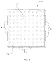
- Figure 3 shows the section view of the same body (2) which can be observed in the preceding figure ( Figure 2 ), one of the sides of said body (2) thus being seen.
- the plurality of protrusions (3) with a flat base (3.1), uniformly distributed on the first surface (2.1) and positioned perpendicular to said first surface (2.1), can also be observed in this figure.
- the volume of air housed between pairs of protrusions (3) is uniform, since said protrusions (3) are homogeneous and uniformly distributed on the second surface (2.2). Said chambers (Q) are communicated with one another, being a common space between all the protrusions (3) and the roof (C).
- Figure 4 shows the plan view of the assembly of two insulation boards (1). Said assembly takes place by means of coupling one side of each board (1), the assembly of three additional boards (1) on the remaining sides of each of the boards (1) shown being possible.
- the two boards (1) are coupled through the configuration of slots (4.1) and projections (4.2) on the side to be coupled of each body (2) of board (1), positioned in a corresponding manner, matching up the slots (4.1) of one of the boards (1), on the left in the figure, with the projections of the adjacent board (1), on the right in the figure.
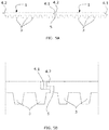
- Figure 7 shows a plurality of insulation boards (1) configured according to the preceding embodiment, once said boards have been assembled on the roof (C) of the building.
- boards (1) adjacent to one another form ventilation openings (5) through which there circulates the air coming from the common chamber generated between the surface of the roof (C) and the first surface (2.1) of each board (1) due to the space generated between said surfaces by the plurality of protrusions (3).
- Figures 6A and 6B show a second embodiment of an insulation board (1).
- Figure 6A shows a plan view of two adjacent insulation boards (1) already assembled together through the coupling of one side of each body (2) of each of the boards (1).
- This coupling of both flat boards (1) allows defining a parallel surface at the same level, keeping plane (X) defined for each of the boards (1), as occurred in the assembly of Figures 5A and 5B .
- the two boards (1) are coupled through the configuration of slots (4.1) and projections (4.2) on the side to be coupled of each body (2) of board (1), positioned in a corresponding manner, and said slots (4.1) alternating with said projections (4.2) along the perimeter of each body (2).
- each protrusion (3) is integral with the surface of the body (2), with no attachments or couplings between them. This allows the protrusions (3) to be distributed homogeneously and continuously, formed directly on the first surface (2.1) of each board (1). Like in the preceding examples, these protrusions (3) form a continuous cavity (Q) through which there circulates air between the roof (C) on which they are assembled and the outside.
- the ventilation opening (5) is defined with a straight path, where said path is flared in one area, an intermediate additional cavity being formed between the first surface (2.1) of each board (1) and the outside.
- This opening (5) comprising the mentioned flaring of its path allows the communication of the first surfaces (2.1) with the outside of the second surfaces (2.2) of both bodies (2), thereby allowing air flow from the chamber (Q) formed on the roof (C) of the building.
Landscapes
- Engineering & Computer Science (AREA)
- Architecture (AREA)
- Civil Engineering (AREA)
- Structural Engineering (AREA)
- Building Environments (AREA)
- Roof Covering Using Slabs Or Stiff Sheets (AREA)
Priority Applications (2)
| Application Number | Priority Date | Filing Date | Title |
|---|---|---|---|
| EP20382488.3A EP3919704B1 (de) | 2020-06-05 | 2020-06-05 | Isolierplatte |
| ES20382488T ES3052988T3 (en) | 2020-06-05 | 2020-06-05 | Insulation board |
Applications Claiming Priority (1)
| Application Number | Priority Date | Filing Date | Title |
|---|---|---|---|
| EP20382488.3A EP3919704B1 (de) | 2020-06-05 | 2020-06-05 | Isolierplatte |
Publications (2)
| Publication Number | Publication Date |
|---|---|
| EP3919704A1 true EP3919704A1 (de) | 2021-12-08 |
| EP3919704B1 EP3919704B1 (de) | 2025-08-20 |
Family
ID=71846344
Family Applications (1)
| Application Number | Title | Priority Date | Filing Date |
|---|---|---|---|
| EP20382488.3A Active EP3919704B1 (de) | 2020-06-05 | 2020-06-05 | Isolierplatte |
Country Status (2)
| Country | Link |
|---|---|
| EP (1) | EP3919704B1 (de) |
| ES (1) | ES3052988T3 (de) |
Citations (5)
| Publication number | Priority date | Publication date | Assignee | Title |
|---|---|---|---|---|
| FR2574454A1 (fr) * | 1984-12-06 | 1986-06-13 | Dirand Michel | Materiau utilisable pour la realisation de la couche d'isolation thermique d'un revetement de toiture et revetement de toiture comportant un tel materiau |
| US5144782A (en) * | 1990-08-15 | 1992-09-08 | Paquette Jean Paul | Double-level drainage system for flat roofs |
| DE29902769U1 (de) * | 1998-09-17 | 2000-01-27 | Gutjahr, Walter, 64404 Bickenbach | Drain- und Dämmelement |
| ITMI20090501A1 (it) * | 2009-03-30 | 2010-09-30 | Over All Srl | Pannello isolante termo-acustico per murature |
| CN110821052A (zh) * | 2019-10-23 | 2020-02-21 | 中建科技有限公司 | 一种仿古建筑瓦屋面及施工方法 |
-
2020
- 2020-06-05 EP EP20382488.3A patent/EP3919704B1/de active Active
- 2020-06-05 ES ES20382488T patent/ES3052988T3/es active Active
Patent Citations (5)
| Publication number | Priority date | Publication date | Assignee | Title |
|---|---|---|---|---|
| FR2574454A1 (fr) * | 1984-12-06 | 1986-06-13 | Dirand Michel | Materiau utilisable pour la realisation de la couche d'isolation thermique d'un revetement de toiture et revetement de toiture comportant un tel materiau |
| US5144782A (en) * | 1990-08-15 | 1992-09-08 | Paquette Jean Paul | Double-level drainage system for flat roofs |
| DE29902769U1 (de) * | 1998-09-17 | 2000-01-27 | Gutjahr, Walter, 64404 Bickenbach | Drain- und Dämmelement |
| ITMI20090501A1 (it) * | 2009-03-30 | 2010-09-30 | Over All Srl | Pannello isolante termo-acustico per murature |
| CN110821052A (zh) * | 2019-10-23 | 2020-02-21 | 中建科技有限公司 | 一种仿古建筑瓦屋面及施工方法 |
Also Published As
| Publication number | Publication date |
|---|---|
| EP3919704B1 (de) | 2025-08-20 |
| ES3052988T3 (en) | 2026-01-16 |
Similar Documents
| Publication | Publication Date | Title |
|---|---|---|
| CA2502386C (en) | Moisture control strip | |
| CN1075585C (zh) | 具有改进的阻燃性的组装式预制护墙板 | |
| US5964067A (en) | Prefabricated building elements, and process for producing the same and for building with them | |
| EP1126094B1 (de) | Vorgefertigte Betonplatte für industrialisiertes Bauen, mit hoher Warm- und/oder Schallisolation | |
| EP3919704A1 (de) | Isolierplatte | |
| WO2009134137A2 (en) | Thermally insulating building construction element assembly, and timber or lumber member for same | |
| KR101975227B1 (ko) | 조립식 전기 온돌패널 | |
| EP3835504B1 (de) | Dämmungs- und trocknungsplatte, wärmedämmungs- und trocknungssystem für wände und montageverfahren für das wärmedämmungs- und trocknungssystem für wände | |
| KR100493133B1 (ko) | 건축용 벽돌 | |
| KR101397608B1 (ko) | 건축 조립용 2중 단열패널 | |
| KR100973169B1 (ko) | 건축용 단열판재 및 그 제조방법 | |
| KR101975226B1 (ko) | 전기 온돌패널 | |
| KR200241322Y1 (ko) | 합성수지재 건축구조물 단열매트 | |
| EP0935031A2 (de) | Baublock | |
| KR100418963B1 (ko) | 조립식 황토 패널과 그 제조방법 | |
| KR101770961B1 (ko) | 단열성과 통기성을 조절할 수 있는 황토벽체 및 그 시공 방법 | |
| KR200254904Y1 (ko) | 건축용 벽돌 | |
| KR100458382B1 (ko) | 건축용 블록 | |
| RU2240402C2 (ru) | Блок стеновой комбинированный | |
| JPS6238502B2 (de) | ||
| KR200292419Y1 (ko) | 건축용 블록 | |
| KR200273539Y1 (ko) | 건축용 블록 | |
| KR20140094250A (ko) | 폴리에스터 압착보드를 이용한 조립식 온돌패널 및 그 시공방법 | |
| KR200286068Y1 (ko) | 건축용 블록 | |
| JP2024008107A (ja) | 断熱パネル |
Legal Events
| Date | Code | Title | Description |
|---|---|---|---|
| PUAI | Public reference made under article 153(3) epc to a published international application that has entered the european phase |
Free format text: ORIGINAL CODE: 0009012 |
|
| STAA | Information on the status of an ep patent application or granted ep patent |
Free format text: STATUS: THE APPLICATION HAS BEEN PUBLISHED |
|
| AK | Designated contracting states |
Kind code of ref document: A1 Designated state(s): AL AT BE BG CH CY CZ DE DK EE ES FI FR GB GR HR HU IE IS IT LI LT LU LV MC MK MT NL NO PL PT RO RS SE SI SK SM TR |
|
| B565 | Issuance of search results under rule 164(2) epc |
Effective date: 20201026 |
|
| STAA | Information on the status of an ep patent application or granted ep patent |
Free format text: STATUS: REQUEST FOR EXAMINATION WAS MADE |
|
| 17P | Request for examination filed |
Effective date: 20220607 |
|
| RBV | Designated contracting states (corrected) |
Designated state(s): AL AT BE BG CH CY CZ DE DK EE ES FI FR GB GR HR HU IE IS IT LI LT LU LV MC MK MT NL NO PL PT RO RS SE SI SK SM TR |
|
| STAA | Information on the status of an ep patent application or granted ep patent |
Free format text: STATUS: EXAMINATION IS IN PROGRESS |
|
| 17Q | First examination report despatched |
Effective date: 20230725 |
|
| RIN1 | Information on inventor provided before grant (corrected) |
Inventor name: ALONSO ROHNER, EVELYN Inventor name: LLORCA AFONSO, EVA MARIA Inventor name: GARCIA SANCHEZ, HECTOR JULIAN Inventor name: SOSA DIAZ-SAAVEDRA, JOSE ANTONIO |
|
| GRAP | Despatch of communication of intention to grant a patent |
Free format text: ORIGINAL CODE: EPIDOSNIGR1 |
|
| STAA | Information on the status of an ep patent application or granted ep patent |
Free format text: STATUS: GRANT OF PATENT IS INTENDED |
|
| INTG | Intention to grant announced |
Effective date: 20250326 |
|
| GRAS | Grant fee paid |
Free format text: ORIGINAL CODE: EPIDOSNIGR3 |
|
| GRAA | (expected) grant |
Free format text: ORIGINAL CODE: 0009210 |
|
| STAA | Information on the status of an ep patent application or granted ep patent |
Free format text: STATUS: THE PATENT HAS BEEN GRANTED |
|
| AK | Designated contracting states |
Kind code of ref document: B1 Designated state(s): AL AT BE BG CH CY CZ DE DK EE ES FI FR GB GR HR HU IE IS IT LI LT LU LV MC MK MT NL NO PL PT RO RS SE SI SK SM TR |
|
| REG | Reference to a national code |
Ref country code: GB Ref legal event code: FG4D |
|
| REG | Reference to a national code |
Ref country code: CH Ref legal event code: EP |
|
| REG | Reference to a national code |
Ref country code: IE Ref legal event code: FG4D |
|
| REG | Reference to a national code |
Ref country code: DE Ref legal event code: R096 Ref document number: 602020056897 Country of ref document: DE |
|
| REG | Reference to a national code |
Ref country code: NL Ref legal event code: FP |
|
| PG25 | Lapsed in a contracting state [announced via postgrant information from national office to epo] |
Ref country code: IS Free format text: LAPSE BECAUSE OF FAILURE TO SUBMIT A TRANSLATION OF THE DESCRIPTION OR TO PAY THE FEE WITHIN THE PRESCRIBED TIME-LIMIT Effective date: 20251220 |
|
| PG25 | Lapsed in a contracting state [announced via postgrant information from national office to epo] |
Ref country code: NO Free format text: LAPSE BECAUSE OF FAILURE TO SUBMIT A TRANSLATION OF THE DESCRIPTION OR TO PAY THE FEE WITHIN THE PRESCRIBED TIME-LIMIT Effective date: 20251120 |
|
| REG | Reference to a national code |
Ref country code: LT Ref legal event code: MG9D |
|
| PG25 | Lapsed in a contracting state [announced via postgrant information from national office to epo] |
Ref country code: PT Free format text: LAPSE BECAUSE OF FAILURE TO SUBMIT A TRANSLATION OF THE DESCRIPTION OR TO PAY THE FEE WITHIN THE PRESCRIBED TIME-LIMIT Effective date: 20251222 |
|
| PG25 | Lapsed in a contracting state [announced via postgrant information from national office to epo] |
Ref country code: FI Free format text: LAPSE BECAUSE OF FAILURE TO SUBMIT A TRANSLATION OF THE DESCRIPTION OR TO PAY THE FEE WITHIN THE PRESCRIBED TIME-LIMIT Effective date: 20250820 |
|
| PG25 | Lapsed in a contracting state [announced via postgrant information from national office to epo] |
Ref country code: HR Free format text: LAPSE BECAUSE OF FAILURE TO SUBMIT A TRANSLATION OF THE DESCRIPTION OR TO PAY THE FEE WITHIN THE PRESCRIBED TIME-LIMIT Effective date: 20250820 |
|
| PG25 | Lapsed in a contracting state [announced via postgrant information from national office to epo] |
Ref country code: GR Free format text: LAPSE BECAUSE OF FAILURE TO SUBMIT A TRANSLATION OF THE DESCRIPTION OR TO PAY THE FEE WITHIN THE PRESCRIBED TIME-LIMIT Effective date: 20251121 |
|
| REG | Reference to a national code |
Ref country code: ES Ref legal event code: FG2A Ref document number: 3052988 Country of ref document: ES Kind code of ref document: T3 Effective date: 20260116 |
|
| PG25 | Lapsed in a contracting state [announced via postgrant information from national office to epo] |
Ref country code: SE Free format text: LAPSE BECAUSE OF FAILURE TO SUBMIT A TRANSLATION OF THE DESCRIPTION OR TO PAY THE FEE WITHIN THE PRESCRIBED TIME-LIMIT Effective date: 20250820 |
|
| PG25 | Lapsed in a contracting state [announced via postgrant information from national office to epo] |
Ref country code: LV Free format text: LAPSE BECAUSE OF FAILURE TO SUBMIT A TRANSLATION OF THE DESCRIPTION OR TO PAY THE FEE WITHIN THE PRESCRIBED TIME-LIMIT Effective date: 20250820 |
|
| PG25 | Lapsed in a contracting state [announced via postgrant information from national office to epo] |
Ref country code: BG Free format text: LAPSE BECAUSE OF FAILURE TO SUBMIT A TRANSLATION OF THE DESCRIPTION OR TO PAY THE FEE WITHIN THE PRESCRIBED TIME-LIMIT Effective date: 20250820 Ref country code: PL Free format text: LAPSE BECAUSE OF FAILURE TO SUBMIT A TRANSLATION OF THE DESCRIPTION OR TO PAY THE FEE WITHIN THE PRESCRIBED TIME-LIMIT Effective date: 20250820 |
|
| PG25 | Lapsed in a contracting state [announced via postgrant information from national office to epo] |
Ref country code: RS Free format text: LAPSE BECAUSE OF FAILURE TO SUBMIT A TRANSLATION OF THE DESCRIPTION OR TO PAY THE FEE WITHIN THE PRESCRIBED TIME-LIMIT Effective date: 20251120 |
|
| REG | Reference to a national code |
Ref country code: AT Ref legal event code: MK05 Ref document number: 1827443 Country of ref document: AT Kind code of ref document: T Effective date: 20250820 |
|
| PG25 | Lapsed in a contracting state [announced via postgrant information from national office to epo] |
Ref country code: SM Free format text: LAPSE BECAUSE OF FAILURE TO SUBMIT A TRANSLATION OF THE DESCRIPTION OR TO PAY THE FEE WITHIN THE PRESCRIBED TIME-LIMIT Effective date: 20250820 |
|
| PG25 | Lapsed in a contracting state [announced via postgrant information from national office to epo] |
Ref country code: DK Free format text: LAPSE BECAUSE OF FAILURE TO SUBMIT A TRANSLATION OF THE DESCRIPTION OR TO PAY THE FEE WITHIN THE PRESCRIBED TIME-LIMIT Effective date: 20250820 |
|
| PG25 | Lapsed in a contracting state [announced via postgrant information from national office to epo] |
Ref country code: AT Free format text: LAPSE BECAUSE OF FAILURE TO SUBMIT A TRANSLATION OF THE DESCRIPTION OR TO PAY THE FEE WITHIN THE PRESCRIBED TIME-LIMIT Effective date: 20250820 |